

Page 1
ILTT Operating Instructions
ELECTROMATIC Equip’t Co., Inc
600 Oakland Ave.
Cedarhurst, NY 11516
Tel: 800-645-4330 / 516-295-4300
Fax: 516-295-4399
Email: info@checkline.com
Website: www.checkline.com
Page 2

CONTENTS 1
CONTENTS
CONTENTS ...................................................1
INTRODUCTION.............................................2
Description ......................................................... 2
System Specifications......................................... 2
OPERATION ..................................................3
Display Operation ............................................... 3
Sample Mode ..................................................... 3
Program menu .................................................... 3
Number edit mode .............................................. 4
Side Panel Inputs................................................ 5
DC In............................................................... 5
RS-232........................................................... 5
Charging the Batteries......................................... 5
RS-232............................................................... 6
RS232 Transfer Protocol.................................. 6
RS232 Datastream Format.............................. 6
RS232 Cable Pinouts ...................................... 6
DESCRIPTION OF FUNCTIONS ........................ 7
Operating Mode.................................................. 7
Peak ............................................................... 7
1st Peak ......................................................... 7
Track............................................................... 7
Engineering Units................................................ 7
Full Scale............................................................ 7
Low Limit ............................................................ 7
High Limit ........................................................... 7
SERVICE AND WARRANTY .............................. 8
AWS-QCGuide
Page 3
INTRODUCTION 2
y
y
INTRODUCTION
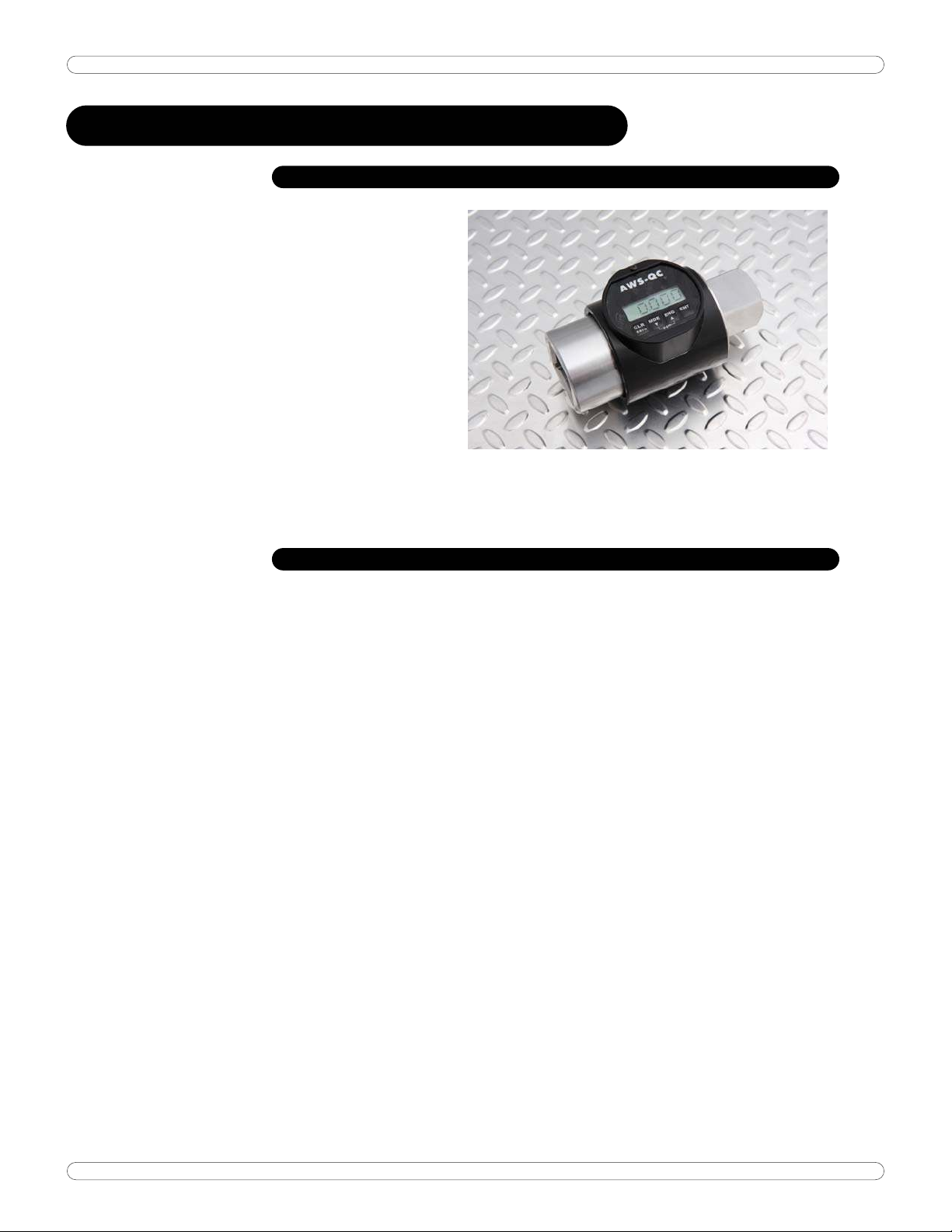
DESCRIPTION
The AWS Inline QC Torque Tester
is designed to provide for a wide
range of torque testing
applications in the smallest foot
print at a very reasonable price.
Features include an LCD graphics
display, built-in battery pack for
remote testing and serial output
for use with a serial printer or
Windows PC. (High capacity
model shown here, available in
capacities from 1000-5000 Foot
Pounds. Manual cover shows normal capacity models available from 100 in-lb to 750
Pounds. Manual cover shows normal capacity models available from 100 in-lb to 750
Foot pounds. Other capacities may be available upon reque
Foot pounds. Other capacities may be available upon request.) st.)
SYSTEM SPECIFICATIONS SYSTEM SPECIFICATIONS
DimensionsDimensions
Power RequirementsPower Requirements
Operating Temperature RangeOperating Temperature Range
Data CommunicationsData Communications
AccuracAccurac
Range
Displa
Units
Filter
Width: 3.125", Height: 3.75", Depth: 3.23", Weight:2.5
Width: 3.125", Height: 3.75", Depth: 3.23", Weight:2.5
Lbs.
Lbs.
9-26V DC, 150 mA min (120V mains adapter standard,
9-26V DC, 150 mA min (120V mains adapter standard,
240v mains adapter avaliable) and internal NiMH batteries.
240v mains adapter avaliable) and internal NiMH batteries.
0˚C to 50˚C 0˚C to 50˚C
RS-232-C RS-232-C
1% of Indicated Reading with AWS series transducers.
10% to 100% of Rated Capacity for 1% accuracy.
4 1/2 active digits (displays readings from 19999 to 0.001,
positive or negative, in any units)
Eight (8) available engineering units: Oz.in., Lb.in., Lb.ft.,
Nm, cNm, KgfCm, gfCm, Kgfm.
Special units available, please inquire.
Selectable power tool filtering speeds: 125Hz, 250Hz,
500Hz, 750 Hz, 1500Hz
AWS-QCGuide
Page 4

OPERATION 3
OPERATION
DISPLAY OPERATION
Button Function:
Powering on and off
Press any Key to turn the unit on.
Press CLR and ENT simultaneously to turn the unit off.
ENT
Sends the current reading to the serial port and clears the current peak.
MDE
Displays the current mode for 1 second. Pressing MDE again while the mode is
displayed will change the mode. Any other button will return to sample mode.
ENG
Displays the current units for 1 second. Pressing ENG again while the units are
displayed will change the units. Any other button will return to sample mode.
CLR
Clears the current peak or zeros the transducer if no peak is current.
ENT+CLR
Turns off the display. Press any key to turn on the display.
MDE+ENG
Displays the program menu. See below.
SAMPLE MODE
Sample mode is the normal operating mode used for measurement. When a
measurement is taken, the current transducer sample or current peak is
displayed. If a peak is inside the low and high limits, or the limit(s) is/are off,
the LED will light up green. Otherwise, the LED will light up red to warn the
user that the measurement is out of limits.
PROGRAM MENU
The program menu alternates display of the item name and the current setting.
The program menu will time out after 5 seconds without a button press. All
settings will be saved and the display will return to sample mode.
AWS-QCGuide
Page 5

OPERATION 4
Buttons for menu navigation:
Up (ENG): Go to the next item.
Down (MDE): Go to the previous item.
CLR: Exit back to sample mode and save all settings.
ENT: Change the current item.
Menu Items: (Some models may not have all menu items)
A.C.: Autoclear time, in seconds. Off, 1 - 9
FILT: Peak filter frequency response, in hertz. 125, 250, 500, 750, 1500.
PPER: Minimum peak, percentage of full scale. 2 - 50.
S.L.: Sign lock. On, Off.
LOW: Lower limit. A setting of 0.000 disables the limit. Press ENT to enter the
number edit mode. (see below)
HIGH: Upper limit. A setting of 0.000 disables the limit. Press ENT to enter the
number edit mode. (see below)
F.S.: Full scale in the current units. Not editable.
SLEEP: Inactive time to sleep, in minutes. Inactive time is when no buttons are
pressed and the transducer is in zero blanking. Off, 1 - 20.
NUMBER EDIT MODE
The current digit or decimal point flashes. Number edit mode never times out.
ENT
Save the current digit and go to the next digit. After editing the digits, the
decimal point can be moved. After the decimal point is saved, ENT exits
number edit mode and saves the number that was edited. During the decimal
point edit, the decimal point can be moved to a position where all of the digits
flash. If ENT is pressed at this point the number saved will be 0.000.
Up (ENG)
Increases the current digit or moves the decimal point to the right.
Down (MDE)
Decreases the current digit or moves the decimal point to the left.
AWS-QCGuide
Page 6

OPERATION 5
CLR
Cancels number edit mode and restores the previous number.
SIDE PANEL INPUTS
The side of the AWS-QC contains two interface connections:
DC In
The interface for the AC Adapter supplied with the unit. Use this if you plan on
working under Mains power. Use only the AC adapter provided with the unit.
Use of another power source will void the warranty and may cause severe
damage to the display.
RS-232
If you are downloading to a printer, data collector, computer, etc., this is the
mini-plug interface for the RS-232 cable. Values are sent via RS-232 every
time the unit auto-clears or the ENT/clr button is pressed.
CHARGING THE BATTERIES
1. The batteries in this system should last approximately 12 hours when fully
charged. The batteries are trickle-charged any time the system is pluggedin, and take about 8 hours to fully charge. The unit does not indicate when
it is charging. It is recommended the tester be plugged in when not in use.
This will not harm the unit and will increase battery life.
Note: If the tester is to be stored for several months, always ensure the battery
is completely charged prior to storage.
AWS-QCGuide
Page 7

OPERATION 6
RS-232
The AWS-QC display can be connected to a printer, computer or data collector
via its RS232 interface. Values are sent via RS-232 every time the unit autoclears or the ENT/clr button is pressed. Data cables can be made from the
drawing below or purchased from AWS. We also offer various software
packages to retrieve data from our units, including the QC.
RS232 Transfer Protocol
Protocol Value
Cable 9 pin to mini-
plug.
Baud 9600
Parity None
Bits 8
S Bit 1
Flow None
RS232 Datastream Format
sdddddbuuuuucl,
s Sign (space or -) c Carriage Return
d Data with Decimal Point l Line Feed
u Units b Blank
RS232 Cable Pinouts
Pin # Description Pin # Description
1 Unused 6 Unused
2 Transmit 7 Unused
3 Receive 8 Unused
4 Unused 9 Unused
5 Ground
where:
AWS-QCGuide
Page 8

DESCRIPTION OF FUNCTIONS
The following is a description of the standard features of the AWS product line.
OPERATING MODE
Peak
Displays and retains the maximum torque exerted by the wrench, as occurs
when operating the wrench in the tightening direction. The Peak Mode is used
for all power tools and some dial wrenches.
1st Peak
Detects the “first peak” of torque experienced by the wrench, capturing the
initial torque as occurs when the torque wrench cams over. First Peak is used
primarily for Click torque wrenches and cam over screwdrivers.
Track
Displays torque as it is being applied to the transducer. Track mode is used
primarily for verifying calibration of the unit.
ENGINEERING UNITS
Shows the current engineering units. Press the key to cycle through the eight
possible choices: Kgf m, KgfCm, gfCm, cNm, Nm, FT LB, IN LB, IN OZ.
FULL SCALE
This screen shows the Full-Scale value of the Torque Shaft. This is not a field
adjustable value.
LOW LIMIT
Use the low limit setting as a means of visually flagging the operator when a
reading fails to reach a desired minimum value. A small down arrow will appear
on the screen if a peak is captured below the limit setting.
HIGH LIMIT
Use the high limit setting as a means of visually flagging the operator when a
reading falls over a desired maximum value. High limits are set in the identical
way as low limits. Please refer to the Low Limit section for details.
NOTE ON LIMITS: The green LED on the front of the display will flash when a
peak is captured that falls within the limit setting.
AWS-QCGuide
Page 9

SERVICE AND WARRANTY
SERVICE
To ensure the best possible support for our customers, Advanced Witness Series maintains a
complete calibration and repair facility for all its products. We keep in stock most replacement
parts for torque testers, transducers, and our line of digital wrenches. When you buy a product
from us, the only place you need to go for parts and service is...us! For service, call (408) 4535070, Monday through Friday, between the hours of 9:00am and 5:00pm Pacific Coast Time.
THE WARRANTY CARD
In order to ensure protection of the warranty as described below, you MUST fill in the
appropriate information on the warranty card that came with your unit and return it to Advanced
Witness Series, Inc. within 30 days of receipt of item.
We wish to call your attention to the fact that this system and various components need
calibration and certification on a periodic basis. By returning the card to us, you will receive
timely notification as to when this re-calibration and re-certification is due.
STATEMENT OF LIMITED WARRANTY
ADVANCED WITNESS SERIES, INC. products are warranted free of defects in material and
workmanship for a period of one (1) year from date of shipment. This warranty does not
include failures due to application of torque to transducers or loaders beyond the stated
capacity, operating system with a damaged transducer cord, nor any other misuse, abuse, or
tampering. When used with impact type wrenches, the warranty is limited to the electronic
digital display units only. This warranty does not cover calibrations.
All freight charges are the responsibility of the company or individual returning the item(s) for
repair. Freight collect shipments will not be accepted.
Any modification to any of this equipment, without the express written approval of ADVANCED
WITNESS SERIES, INC., will void this warranty. ADVANCED WITNESS SERIES disclaims any and
all liability, obligation or responsibility for the modified product; and any claims, demands or
causes of action for damage or for personal injuries resulting from the modification and/or use
of such a modified ADVANCED WITNESS SERIES product.
ADVANCED WITNESS SERIES, INC.'S OBLIGATION WITH RESPECT TO ITS PRODUCTS SHALL BE
LIMITED TO REPAIR OR REPLACEMENT, AND IN NO EVENT, SHALL ADVANCED WITNES SERIES, INC.
BE LIABLE FOR ANY LOSS OR DAMAGE, CONSEQUENTIAL OR SPECIAL, OF WHATEVER KIND OR
NATURE OR ANY OTHER EXPENSE WHICH MAY ARISE IN CONNECTION WITH OR AS A RESULT OF
SUCH PRODUCTS OR THE USE OR INFORMATION THEREOF IN A JOB. THIS WARRANTY IS EXPRESSLY
MADE IN LIEU OF ALL OTHER WARRANTIES OR MERCHANTABILITY AND FITNESS FOR A PARTICULAR
PURPOSE. NO EXPRESS WARRANTIES AND NO IMPLIED WARRANTIES WHETHER OF
MERCHANTABILITY OR FITNESS FOR A PARTICULAR PURPOSE OR OTHERWISE OTHER THAN THOSE
EXPRESSLY SET FORTH ABOVE SHALL APPLY TO ADVANCED WITNESS SERIES.
AWS-QCGuide
 Loading...