

Page 1
2 YEAR WARRANTY (RESTRICTIONS APPLY)
Imada, Inc. warrants its products to the original purchaser to be free from defects
in workmanship and material under normal use and proper maintenance for two
years (one year for adapters, attachments and cables) from original purchase. This
warranty shall not be effective if the product has been subject to overload, shock
load, misuse, negligence,accident or repairs attempted by others than Imada, Inc.
During the warranty period, we will, at our option, either repair or replace
defective products. Please call our customer service department for a return
authorization number and return the defective product to us with freight prepaid.
The foregoing warranty constitutes the SOLE AND EXCLUSIVE WARRANTY, and we
hereby disclaim all other warranties, express, statutory or implied, applicable to the
products and/or software, including but not limited to all implied warranties of
merchantability, fitness, non-infringement, results, accuracy, security and freedom
from computer virus. In no event shall Imada, Inc.and/or its affiliated companies be
liable for any incidental, consequential or punitive damages in connection with the
use of its products and/or software.
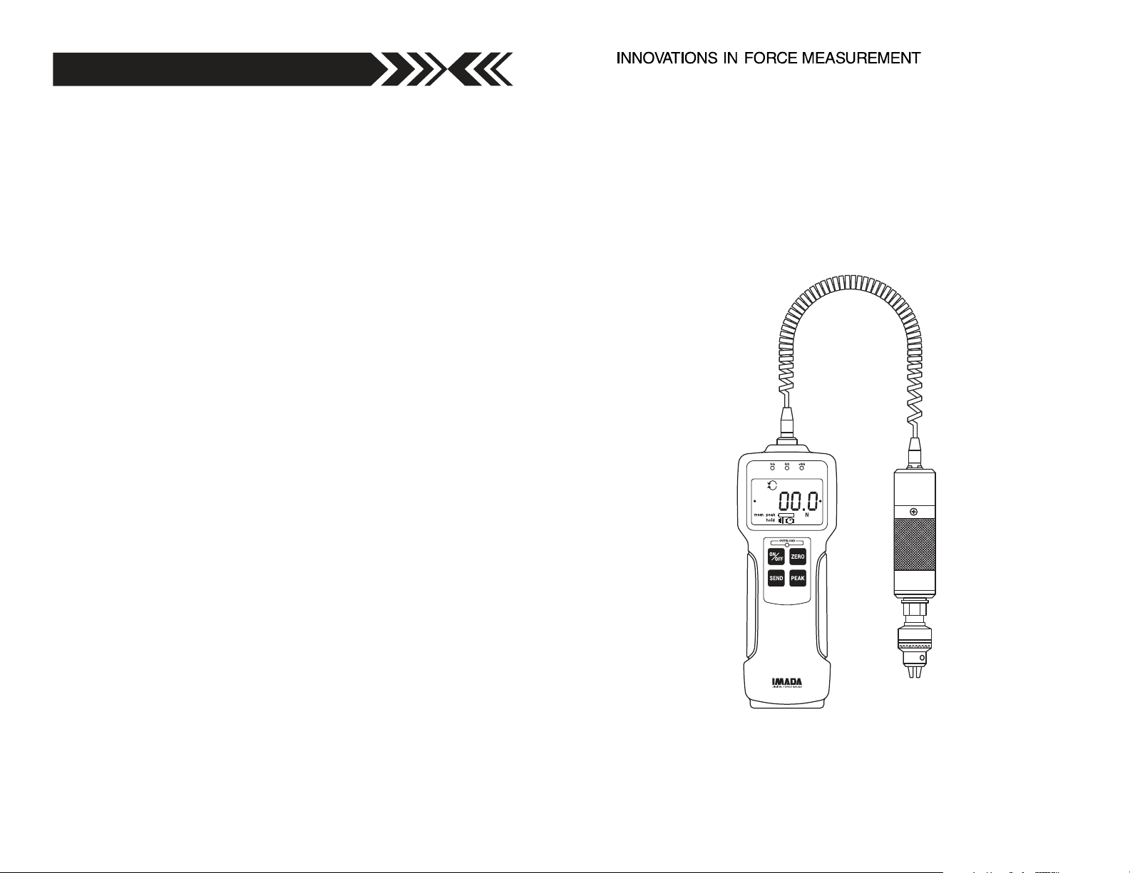
Digital Torque Gauge
Specifications subject to change without notice.
Model HTG2
INSTRUCTION MANUAL
Page 2
INTRODUCTION
Model HTG2 is a highly sophisitcated, torque tester which offers
programmable high/low setpoints for go/no go testing. Store up
to 1,000 values into memory, which can be transmitted using
Digimatic or RS-232 formats. Use the Real Time mode to display
torque transients, or the Peak mode to capture the peak torque
achieved during a test. Select measuring units between lbf-in or
ozf, kgf-cm and N-cm.
PRECAUTIONS
HTG2 Torque Tester is a sensitive instrument. The torque sensor
can be damaged regardless of whether the unit is ON or OFF.
Follow these precautions to keep your HTG2 from being damaged.
1. WARNING!! Do not exceed unit’s capacity regardless if power
is on or off.
2. Only use the Imada AC adapter/charger, other brands may cause
serious damage.
3. Accuracy may be affected if unit is exposed to high humidity,
dust or extreme shock.
4. Do not disassemble unit. Disassembly voids warranty.
5. Recommended re-calibration cycle is one (1) year.
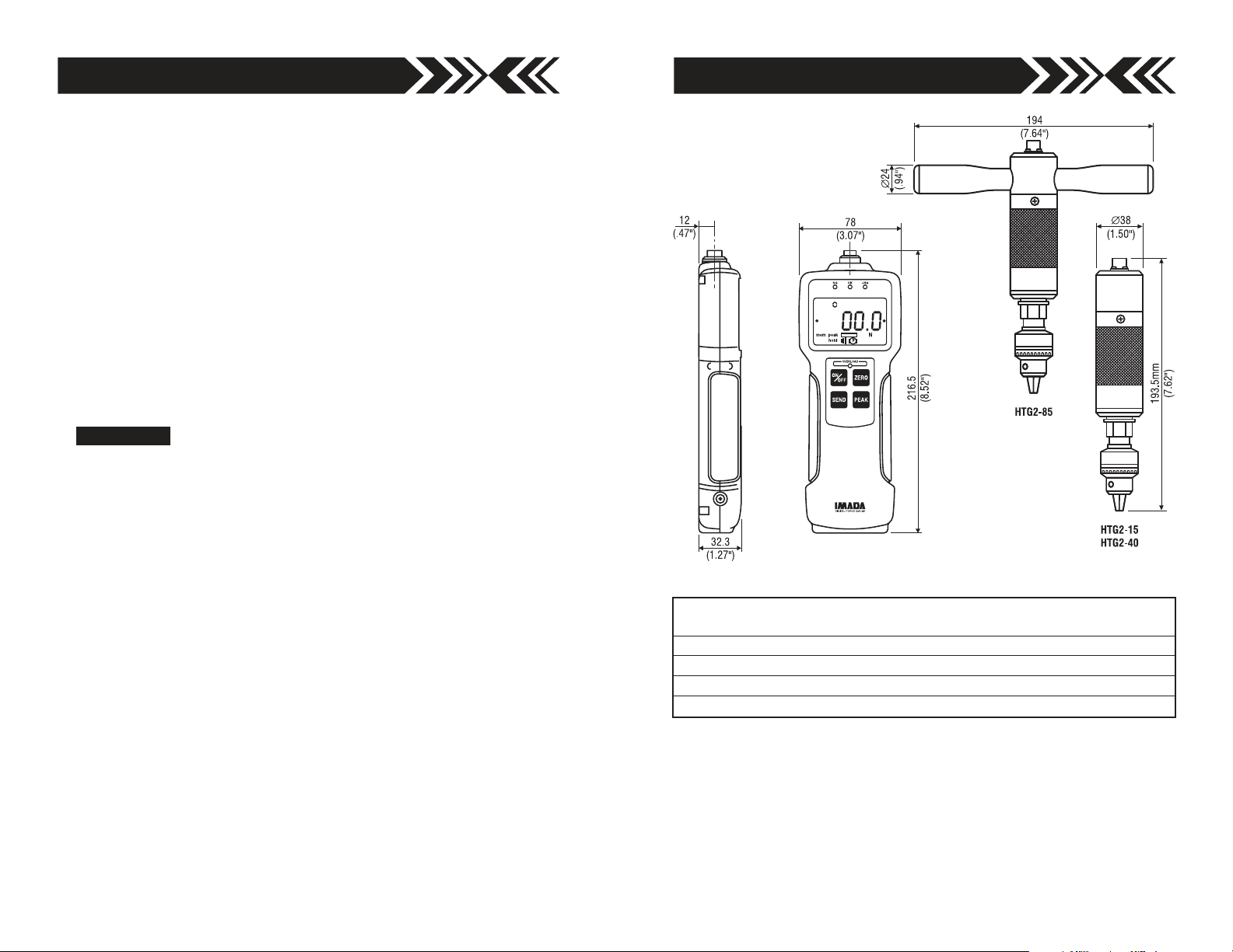
DIMENSIONS
Model Capacity (Resolution)
lbf-in kgf-cm N-cm
HTG2-4 70.00 (0.01 ozf-in) 5.000 (0.001 kgf-cm) 50.00 (0.01 N-cm)
HTG2-15 15.00 (0.01 lbf-in) 20.00 (0.01 kgf-cm) 200.0 (0.1 N-cm)
HTG2-40 40.00 (0.01 lbf-in) 50.00 (0.01 kgf-cm) 500.0 (0.1 N-cm)
HTG2-85 85.0 (0.1 lbf-in) 100.0 (0.1 kgf-cm) 1000 (1 N-cm)
page 15page 2
Page 3
Imada HTG2 Series Specifications
Accuracy ± 0.5% F.S. ± 1 LSD
Selectable Units ozf-in or lbf-in, kgf-cm, and N-cm
Overload Capacity 200% of F.S. Overload indicator flashes beyond 110% of F.S.
Power Rechargeable Ni-MH battery pack or Imada AD120/230 adapter
Battery Indicator Icon flashes when battery is low
Battery Life approx. 8 hours (recharge time approx. 10 hours)
Memory Non-volatile, recall up to 1000 data
Setpoints Programmable high/low setpoints with color-coded LED
indicators and output signal
Outputs RS-232C, Digimatic and ± 2 VDC analog output
Auto Power Off 5, 10, 30, 60 minutes or OFF (selectable)
Operating Temp. 32° to 100°F (0° to 40°C)
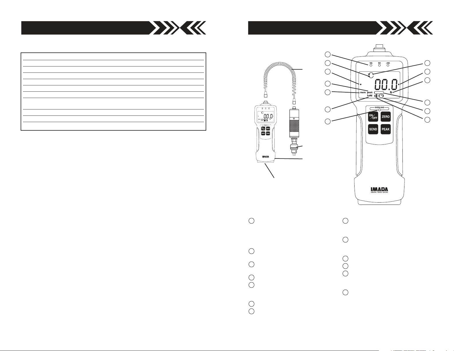
COMMUNICATION PORT
RS-232, DIGIMATIC &
±2VDC ANALOG
CABLE
MEASURING
CHUCK
DISPLAY
UNIT
1
2 3
8
6
9
13
45
12
7
11
10
1
Programmable Setpoint LED’s
When high-low setpoints are set,
LED indicates below (-NG), within
(OK), or above set point value
(+NG).
2
CW icon
Indicates CW measurement.
3
CCW icon
Indicates CCW measurement.
4
Reverse +/– values
5
Auto Zero Reset icon
Programmable auto zero reset
duration
6
Auto Memory - Peak Reset icon
7
Battery icon
Flashes when Ni-MH cells need
charging.
8
PEAK icon
Displays continuously when peak
function is active.
9
HOLD icon
Displays when external hold signal
is active or SEND button is pressed.
10
Alarm Icon
11
Auto Power Off icon
12
Units icon
Displays selected measuring units.
(ozf-in, lbf-in, kgf-cm, N-cm)
13
Overload Indicator
Flashes at 110% of rated capacity.
page 3page 14
Page 4

NG OK +NG
OVER
LO
A
D
ZERO
F
NG OK +NG
A
D
NG OK +NG
A
D
PREPARATION
Connect the coiled cable to both the measuring chuck and display
unit by rotating the round cable connector to find the matching
groove, then pushing in until positive connection is made.
To disconnect, first slide the ribbed cover of the connector back,
then pull out the connector (DO NOT ROTATE THE CONNECTOR).
TURN CONNECTOR TO FIND
THE GROOVE
PUSH IN UNTIL IT MAKES A POSITIVE
CONNECTION
SLIDE THE RIBBED COVER OF THE
CONNECTOR BACK , THEN PULL
OUT THE CONNECTOR
RIBBED COVER
OPERATION
Selecting Units
Press to turn on the gauge. The LCD display briefly shows the
capacity of the gauge and then zero with a measuring unit (facto-
ry setup is lbf-in or ozf-in). If you want to change to other units:
1. Turn off the gauge.
2. Press again while holding to enter Power-Off program-
Power-Off programming (clear data from memory)
Turn off the gauge. Press again while holding to enter
memory mode.
Memory clear
Memory location and value cycle. Press PEAK or ZERO to increase or decrease memory location (and corresponding value).
Single Memory Clear A memory location with a dot at both ends is the last stored data
and the only one that can be erased. Press SEND to erase, ErASEd is displayed. If you
attempt to erase other locations Error is displayed. Press ON/OFF to exit.
All Memory Clear While a memory value or location is displayed, press SEND for 3 seconds, all data is erased and ErASEd is displayed, then – – – – –. Press ON/OFF to exit.
Power-Off programming
Turn off the gauge. Press again while holding to enter
Power-Off programming (CF9 flashes with solid m0). Press or
to cycle CF9m0, CF9m1, CF9m2, CF9m3(USB models
only) and CF9End. Press to select a function.
CF9 m0 Units selection
Press PEAK or ZERO to cycle; ‘U-01’: kgf-cm, ‘U-02’: N-cm, ‘U-03’: lbf-in or ozf-in
Press SEND to select, CF9End displays. Press SEND to exit.
CF9 m1 Torque dampening Factory set=’Fd6’
Press PEAK or ZERO to cycle: ‘Fd0, Fd 1, Fd2, Fd3, Fd4, Fd5 or Fd6’. Torque dampening averages rapid torque changes over time. Larger numbers allow more dampening.
Press SEND to select, CF9End displays, press SEND to exit (Torque dampening rate
displays each time the gauge is turned on).
CF9 m2 +/– indicator Default=’SC-OFF’
Press PEAK or ZERO to cycle. ‘SC-OFF’: CW (+) and CCW (–) or ‘SC-On’: CW (–) and
CCW (+). Press SEND to select, CF9End displays, press SEND to exit.
ming mode (CF9 flashes with solid nn0).
3. Press to display U-03 with a unit, then press or
to cycle desired units (ozf-in, lbf-in, kgf-cm and N-cm), and
press to select (CF9 flashes with solid End).
4. Press to exit 1st. programming mode.
Once units are selected, the gauge retains them as a default.
Note: All power-on and power-off programming functions except for unit selection and
display orientation can be reset to factory defaults by the following procedure.
Turn on the gauge Press PEAK and ZERO for 3 seconds to display flashing CF9 with
solid F0. Press ZERO and PEAK for 5 seconds until flashing CF9 disappears and
becomes only solid F0. Then release both PEAK and ZERO. Gauge goes back to
measuring mode with factory default settings.
page 4 page 13
Page 5

DIGITAL FORCE GAUGE
00.0
NG
Lb-in
OK +NG
OVERLOAD
ZERO
SEND PEAK
ON
OFF
DIGITAL FORCE GAUGE
00.0
NG
Lb-in
OK +NG
OVERLOAD
ZERO
SEND PEAK
ON
OFF
Power-On programming
Turn on the gauge. Press and for 3 seconds to enter
Reversing the Display
The factory default is standard display.
To reverse the display:
Power-On programming (CF9 flashes with solid F0). Press or
to cycle CF9 F0, CF9 F1, CF9 F2, CF9 F3, CF9 F4, CF9 F5,
CF9 F6 and CF9 End. Press to select a function.
CF9 F0 Memory recall
Press SEND, memory location and value cycle. Press PEAK or ZERO to increase or
decrease memory number (and corresponding value). Press SEND to exit.
1. Turn on the gauge
2. Press and for 3 seconds to enter
Power-On programming mode (CF9 flashes
with solid F0).
STANDARD
DISPLAY
3. Press 5 times to display flashing CF9 with solid F5, then
press to display -12345. Press or , to cycle between
CF9 F1 High & low setpoints Default=‘0’ both Hi and Lo
Press SEND, –HI– displays, then the high set value (i.e. H 10.0). Press PEAK to
increase and ZERO to decrease, press SEND to select. –LO– displays then the low set
value (i.e. L 5.0). Press PEAK to increase and ZERO to decrease, press SEND to select,
CF9 End displays. Press SEND again to exit.
CF9 F2 Peak mode Default=‘Or’
Press SEND, ‘Or’ or ‘And’ displays. Press PEAK or ZERO to cycle. Press SEND to
select. ‘Or Peak’ records the Peak in either CW or CCW during test. ‘And Peak’ records
both the CW peak and CCW peak during a test.
Zero reset memory store Default=‘AA-OFF’
Auto memory displays after Peak mode is selected. ‘AA-On’ enables automatic memory
storage and reset to zero. ‘AA-OFF’ turns off auto function. Press PEAK or ZERO to
change. Press SEND to select, CF9End displays, press SEND again to exit.
CF9 F3 Auto zero reset Default=‘Ac-OFF’
Press SEND, ‘Ac-On’ or ‘Ac-OFF’ displays. Press PEAK or ZERO to cycle. If ‘AC-On’ is
selected, auto zero reset duration can be programmed. Press PEAK to increase or
ZERO to decrease. Press SEND to select, CF9End displays, press SEND again to exit
(i.e. ‘SEC 3.0’ is displayed for auto zero reset duration of 3 seconds).
CF9 F4 Audible beep Default=‘Sd-On’
Press SEND, ‘Sd-On’ for alarm on, or ‘SD-OFF’ for off displays. Press PEAK or ZERO to
cycle. Press SEND to select. CF9End displays, press SEND again to exit (alarm sounds
for values over HI or under LO setpoints).
Setpoint alarm Default=’’
Setpoint alarm displays after audible beep is selected. ‘AL-On’ for setpoint alarm on or
‘AL-OFF’ for off. Press PEAK or ZERO to cycle. Press SEND to select, CF9End displays,
press SEND again to exit.
CF9 F5 Reverse display
Press SEND, ‘-12345’ for standard or ’ ’ for reverse displays. Press PEAK or
-12345
ZERO to cycle. Press SEND to select. Flashing CF9 with solid End displays. Press
SEND again to exit. (for vertical mounting).
CF9 F6 Auto power off duration Default=‘AO-10’
Press SEND, ‘AO-10’ displays. Press PEAK or ZERO to cycle ‘AO-5’ for 5 min auto
power off duration, ‘AO-10’ for 10 min, ‘AO-30’ for 30 min, ‘AO-60’ for 60 min and ‘AOOFF’ to by-pass auto power off. Press SEND to select, CF9End displays, press SEND
again to exit.
standard and reverse .
4. Press to select, the display flashes CF9 with solid End.
5 Press again to exit Power-On programming mode.
Once desired display is selected, the gauge retains it as a default.
Programming Setpoints (optional)
Program High and Low setpoints for easy GO/NO GO testing.
1. Turn on the gauge
2. Press and for 3 seconds to enter Power-On program-
ming mode (CF9 flashes with solid F0).
3. Press to display flashing CF9 with solid F1,
then press to display –HI– and then the
high set value (i.e. H 10.0).
4. Press to increase and to decrease the
High set value, then press to display –LO–
and then low set value (i.e. L 5.0). Press to
increase and to decrease the Low set value and press
to display flashing CF9 with solid End.
5. Press again to exit Power-On programming mode.
-12345
HIGH SETPOINT
LOW SETPOINT
page 12 page 5
REVERSE
DISPLAY
Page 6

Peak or Real time Measuring Mode
Press to turn on and the gauge automatically
enters real time measuring mode. For peak mea-
REAL TIME MODE DISPLAY
surement press . The “Peak icon” appears on
the display. Peak readings will not change until a
higher value is measured. Press again to
return to real time mode.
PEAK MODE DISPLAY
“Or PEAK“ is the factory default which measures peak CW torque
or peak CCW torque. “And PEAK“ measures both peak CW torque
and peak CCW torque during a test. Refer to the F2 function of
the Power-On programming table for the “And PEAK” function.
RECHARGING NI-MH BATTERY
1. To maximize the life of the battery, power is automatically shut
off after 10 minutes of non-use or user-defined interval.
Automatic shut off is bypassed during USB output or when
used with the AC adapter/charger.
2. Battery icon will flash when the gauge needs to be
recharged.
3. Push to turn off power. Only use the IMADA AC adapter/
charger provided, AD120 for 115VAC, AD230 for 230VAC. Plug
into the correct AC output. It takes 10 hours to charge fully.
Tare
KEY
Clamp test sample firmly by tightening the
key. If necessary, press to tare before the
test. Pressing also clears the peak reading.
TURN MEASURING
CHUCK BY HAND
If High and Low setpoints have been programmed (see page 5),
for example, 5 lbf-in is set as Low and 10 lbf-in as High, the
ORANGE LED light for measurements less than 5 lbf-in (Low setpoint). GREEN lights between 5–10 lbf-in and RED lights over 10
lbf-in (High setpoint). Setpoint output is available through the
Communications port (see page 7).
After measuring, press the button to transmit data to:
RS-232 models: RS-232C or Digimatic devices
Storing Data into Memory
During measurement whether Peak or Real Time, press to store
and display up to 1000 torque values into memory. (If no data is
stored – – – – – is displayed then flashing CF9 with solid End).
4. When the gauge is turned off, make sure the AC adapter/charger
is disconnected to avoid overcharging.
OPTIONAL CABLES
10' Analog cable
CB-104
10' RS-232C cable, 9 pin female
CB-204
10' Digimatic Cable
CB-304
page 11page 6
Page 7

2. Mitutoyo Digimatic Signal
Connect the CB-304 cable to the communications port and
the device receiving the data. Set up parameters as instructed
from the Mitutoyo processor manual.
Recalling Data from Memory
1. Turn on the gauge.
2. Press and for 3 seconds to enter Power-On program-
ming (CF9 flashes with solid F0). Press and the display
3. ±2 VDC Analog Signal
Connect the CB-104 analog cable to the communications port
and the device receiving the data.
4. External Switch Display Freeze
By connecting #10 and #12
of the communications port,
the gauge instantaneously
captures the critical reading
and holds the display from
remote locations (use contact
closure and DO NOT apply
voltage across #10 and #12).
(1) Pay extra attention to avoid overload as display
value will not change during display hold.
(2) Use contact closure only and DO NOT apply
voltage across #10 and #12 port pins.
5. External Switch Display Clear
By connecting #8 and #12 of the communications port, display can be cleared from remote locations (use contact closure and DO NOT apply voltage across).
cycles memory location and value. Press to increase loca-
tion and to decrease. Press to exit.
Clearing Data from Memory
1. Turn off the gauge.
2. Press again while holding to enter memory mode.
Single Memory Clear
A memory location with a dot at both ends is the last stored value
and the only one that can be erased. Press to erase and ErASEd
is displayed. If you erase any other location Error is displayed.
All Memory Clear
While a memory location or value is displayed, press for 3
seconds, all data is erased, ErASEd is displayed, then – – – – – and
flashing CF9 with solid End. Press to exit. (See page 14-15).
Downloading Data from Memory
Choose between the following download methods.
Digimatic Data Download from Memory
1. Connect the gauge and device receiving data with CB-304 cable.
2. Turn on the gauge. Press and for 3 seconds to enter
Power-On programming (CF9 flashes with solid F0).
3. Press to transmit all data.
Use contact closure only and DO NOT apply voltage
across #8 and #12 port pins.
4. Press again to exit.
RS-232C Data Download from Memory
Connect the gauge and device receiving data with a CB-204
cable. Use the I[CR] ASCII command to transmit data (uppercase
ASCII character format).
page 7page 10
Page 8

COMMUNICATIONS PORT
1
13
14
26
DIGITAL FO
RCE GA
UGE
NG OK
+
NG
0-200N
0-20 kgf 0-44lb
OVERLOAD
ZERO
SEND PEAK
ON
OFF
M
ode
l:
DPZ-200N
1. RS-232C bi-directional interface functions
All functions can be duplicated remotely by using the RS-232C
interface. Commands must be sent in uppercase ASCII character format followed by a carriage return [CR].
RS-232C Signal: 8 data, 1 stop, no parity. Baud Rate: 19200 bps
26 PIN CONNECTOR
RS-232C INTERFACE FUNCTIONS (Upper case ASCII format)
COMMAND FUNCTION RESPONSE*
T[CR] Select real time mode R[CR]
P[CR] Select peak mode R[CR]
If OR peak is programmed
P[CR] = peak
If AND peak is programmed
COMMUNICATIONS PORT PIN DEFINITIONS
PIN# DEFINITION
1 RS-232C Signal Output
2 RS-232C Receive Signal
3 RS-232C Ground
4 Analog Output ±2VDC
5 Analog Ground
6
7
8 External Switch Display Clear
9 External Switch for Peak/Real Time Modes
10 External Switch Display Freeze
11
12 Ground
13 Ground
14
15
16 Digimatic Data Request
17 Digimatic Data Ready
18 Digimatic Data Clock
19 Digimatic Data Signal Out
20 Digimatic Data Ground
21 +NG Output
22 OK Output
23 -NG Output
24 Overload Output
25 Common
26 Common
RS-232C Output
Analog Output
External Inputs
Digimatic Output
High/Low Setpoint and Overload
Output (open collector=
30V, 10mA max)
Z
[CR]
D[CR] Transmit display data [direction][value][units][mode]
V[CR] Transmit Peak data P+[value][units][CR]
g[CR] Continuous data output (10 data/sec)
Y[CR] Stop continuous data output
K[CR] Select “kgf-cm” units R[CR]
N[CR] Select “N-cm” units R[CR]
O[CR] Select “lbf-in” units R[CR]
B[CR] Delete last data stored in memory R[CR]
M[CR] Store data R[CR]
I[CR] Recall memory data Data format is the same as D
C[CR] Clear memory R[CR]
EXXXXYYYY Set high/low setpoints(4 digit) R[CR]
[CR] XXXX=High, YYYY=Low
E[CR] Read high/low EXXXXYYYY[CR]
*Note: E[CR] response if the command is not accepted.
P[CR] (1st time)= +peak
P[CR] (2nd time)= – peak
Tare Display R[CR]
[go/nogo/overload][CR]
[direction] +=CW
–=CCW
[value] 4 digits w/decimal
[units] K, N, or O
[mode] T=real time value
P=peak value
H=Hold value
M=Memory value
[go/nogo] H=+NG
O=OK
L=-NG
E=Overload
P– [value][units][CR]
command response. It will output END[CR] at the end of data
setpoint values (4 digit)
XXXX=High, YYYY=Low
page 8 page 9
 Loading...