

Page 1
2
Introduction
Introduction
Principles of Operation
F probes use the magnetic principle to measure the thickness
of non-magnetic coatings on ferrous metals.
N probes use the eddy current principle to measure the
thickness of non-conductive coatings on non-ferrous metals.
FN probes combine the full abilities of both the "F" and "N"
probes.
Throughout this manual, the symbol indicates more
information about the particular topic or feature is available on our
website. Go to: www.defelsko.com/manuals
NOTE:
Certification
All probes include a Certificate of Calibration. For organizations
with re-certification requirements, gages may be returned at
regular intervals for calibration. DeFelsko recommends that
customers establish gage calibration intervals based upon their
own experience and work environment. Based on our product
knowledge, data and customer feedback, a one year calibration
interval from either the date of calibration, date of purchase, or
date of receipt is a typical starting point.
The PosiTector 6000 hand-held, electronic Gage non-
destructively measures the thickness of coatings on all metals,
quickly and accurately. A PosiTector 6000 consists of a Gage
body and probe (see pg.19).
Plastic Lens Shield
The LCD is covered with a thin plastic film for protection against
fingerprints and other marks during shipment. This film, while
usually removed before using the instrument, can be left in place
to protect against paint overspray. Replacements can be
purchased.
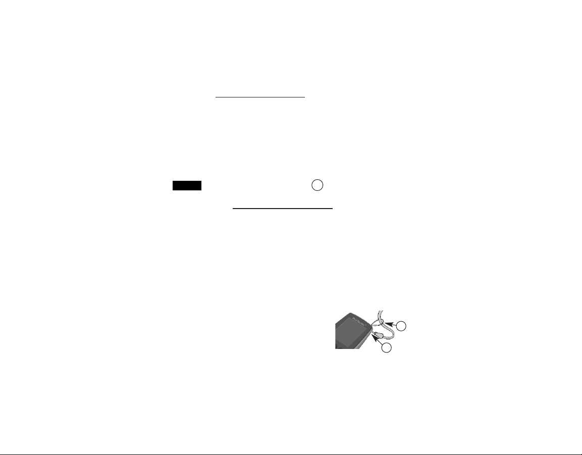
Wrist Strap
We recommend attaching and wearing the
supplied wrist strap.
W
1
2
Page 2
3
1.Remove red protective rubber cap (if supplied) from probe.
2.Power-up Gage by pressing the center navigation button.
3.Place the probe FLAT on the surface to be measured. HOLD
STEADY. When a valid measurement is calculated, the Gage
BEEPS twice and the measurement is displayed.
4.Lift probe AT LEAST 2 INCHES (5cm) from the surface between
measurements - OR - leave probe on the surface in the same
location for continuous measurements.
Golden Rule
Golden Rule
Measure your uncoated part first! This quick zero-check
determines if a calibration adjustment is needed for your
substrate. (see pg.5)
Next, lay the included plastic shims onto a bare surface and
measure them individually to ensure the Gage measures a known
thickness within tolerance.
Operation Overview
Operation Overview
The PosiTector 6000 powers-up when the center navigation
button is pressed. To preserve battery life, the Gage powers-down
after approximately 5 minutes of no activity. All settings are
retained.
If memory is ON while continuous measurements are
being taken, only the last value on the display (when the probe is
lifted) is stored into memory. Scan (pg.17) stores ALL
measurements into memory.
NOTE:
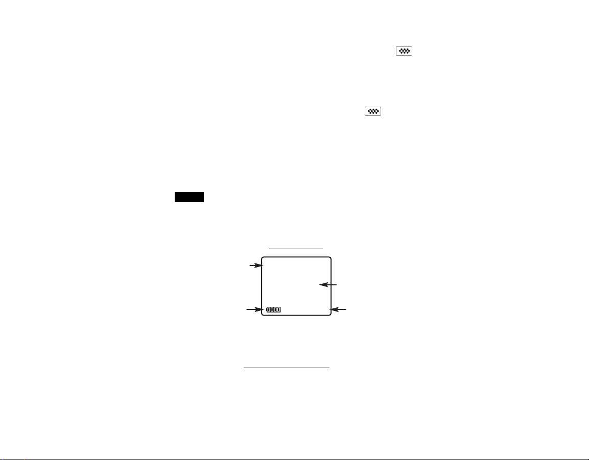
Substrate
Current
Measurement
Battery Indicator
Typical Screen
Unit of
Measurement
Microns
F
56
Page 3
4
Memory
Statistics
Cal Settings
Setup
Connect
Sync Now
USB
Auto Sync
Updates
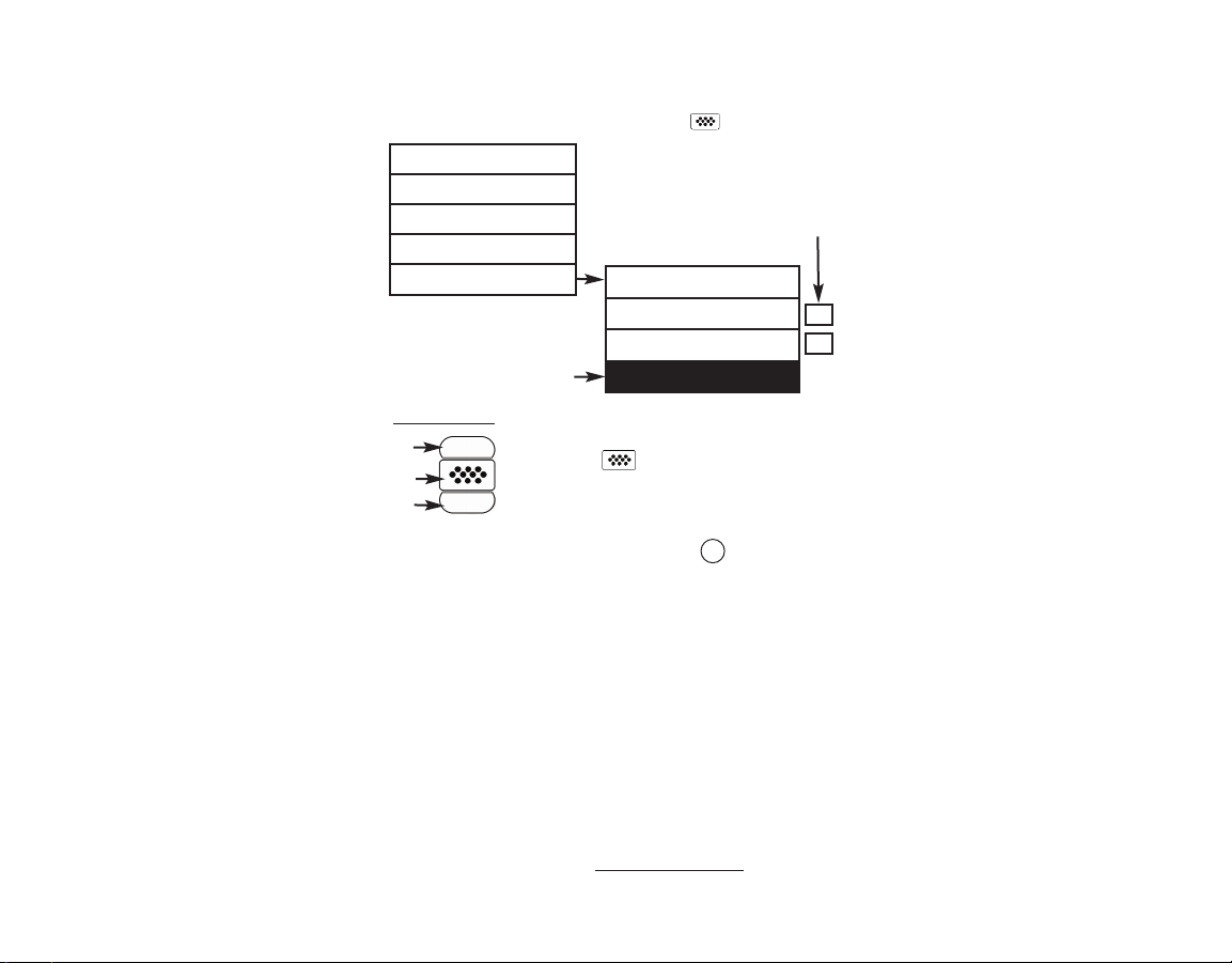
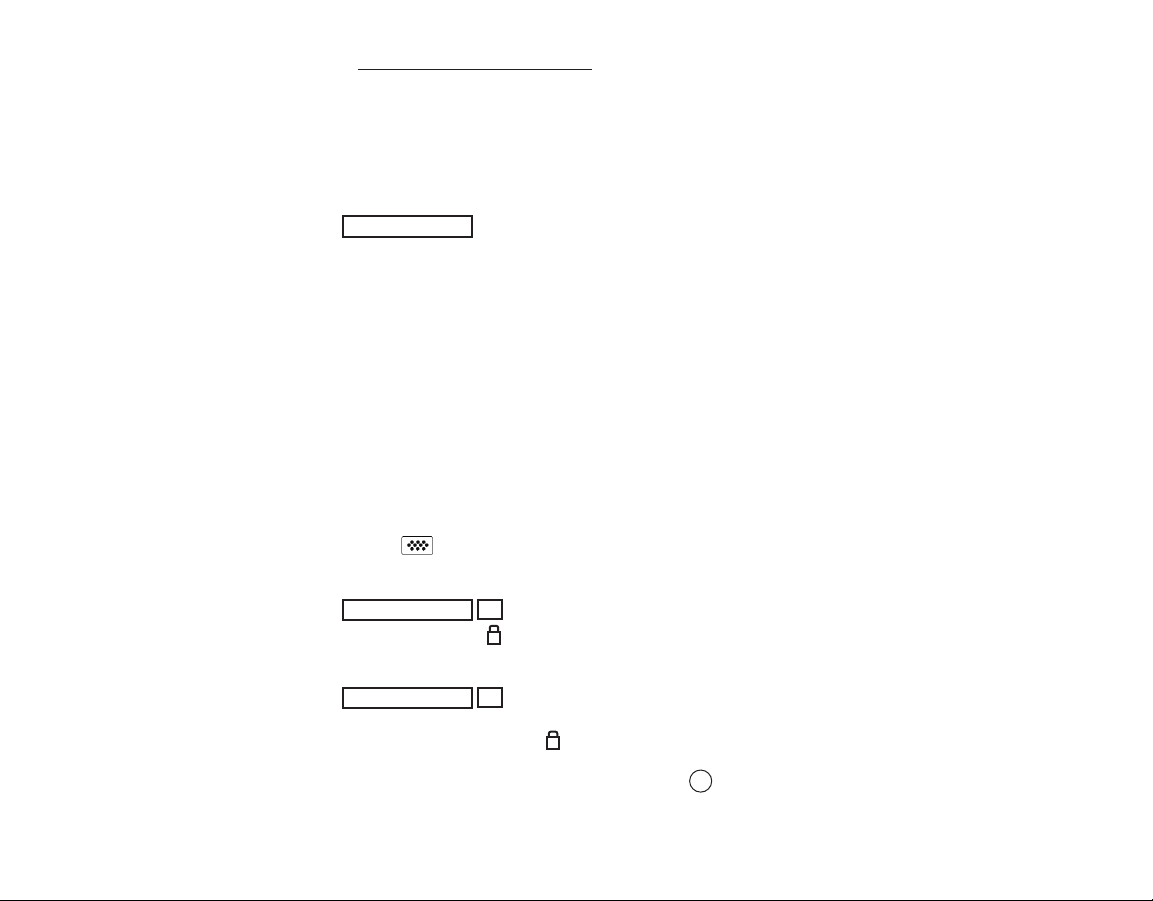
Menu Operation
Menu Operation
Gage functions are menu controlled. To access the Menu, turn the
Gage on, then press the center navigation button.
Some buttons have a tick box to their
right to indicate current status. An empty
box indicates that feature is not active.
Current selection is displayed
with darkened background
Up
Down
Center
To navigate, use the Up and Down buttons to
scroll and to SELECT.
Select Exit to exit from any menu.
ü
Navigation Button
PosiTector.net
PosiTector.net
To enhance the operation of their Gage, all PosiTector users have
access to the features provided by PosiTector.net. It is a free web-
based application offering secure centralized management of
thickness readings.
PosiTector Desktop Manager (PDM) is a small Windows based
application which allows automatic two-way communication
(synchronization) between the Gage and PosiTector.net (internet
connection required). When installed, PDM runs as a start-up
application and resides in the Windows notification area (system
tray) of a PC. PDM is available as a free download within your
PosiTector.net account.
Register your Gage on PosiTector.net to take full advantage of
your gage’s capabilities. Visit: www.PosiTector.net
W
Page 4
5
Calibration, Verification & Adjustment
Calibration, Verification & Adjustment
Three steps ensure best accuracy…
1. Calibration: typically done by the manufacturer or qualified lab
2. Verification of Accuracy: as done by the user
3. Adjustment: to a known thickness
Calibration
Calibration is the controlled and documented process of
measuring traceable calibration standards and verifying that the
results are within the stated accuracy of the Gage. Calibrations
are typically performed by the Gage manufacturer or by a certified
calibration laboratory in a controlled environment using a
documented process.
Verification
Verification is an accuracy check performed by the user using
known reference standards. A successful verification requires the
Gage to read within the combined accuracy of the Gage and the
reference standards.
Adjustment
Adjustment, or Calibration Adjustment is the act of aligning the
Gage's thickness readings to match that of a known sample in
order to improve the effectiveness of the Gage on a specific
surface or in a specific portion of its measurement range. 1-point
or 2-point calibration adjustments are possible.
The symbol disappears whenever a calibration
adjustment is made to the Gage.
The PosiTector 6000 is factory calibrated and performs an
automatic self-check each time it takes a measurement. For
many applications, no further adjustment is necessary after a
Reset (pg.16). Just check ZERO on the uncoated substrate, then
measure.
NOTE:
W
W
Page 5

6
Sometimes Gage readings can be influenced by changes in substrate shape, composition, surface roughness or by measuring in
a different location on the part. This is why Calibration
Adjustments are made possible.
1- or 2-point Calibration Adjustments may be performed if
readings are not falling within the expected range of thickness for
the application being measured.
If a calibration adjustment method has not been specified, use a
1-point method first. If measuring the included shims reveals
inaccuracies, use the 2-point method. Factory Calibration
settings can be restored at any time by performing a Reset
(pg.16), creating a NEW calibration setting (pg.9), or by
DELETING the adjustments made to the Cal 1 calibration setting
(pg.9). The symbol appears on the display whenever factory
calibration settings are in use.
With “FN” probes, calibration adjustments for “F” and “N” prin-
ciples are stored independent of one another.
Once adjusted, you may “lock” the current calibration
adjustment to prevent further modification. (See “Cal Lock” on pg.8)
1-point Calibration Adjustment
Also known as an offset or correction value, there are 4 ways to
perform this adjustment:
(1) Simple
Zero Calibration Adjustment
Measure your uncoated part. If the Gage does not read "0" within the
tolerance of the probe being used, lift the probe from the surface and
adjust the display down (-) or up (+) until it reads "0". Measure and
adjust until the average of a series of readings on the uncoated surface
is within tolerance of "0" .
(2) Average
Zero Calibration Adjustment
To establish “0” on a rough or curved surface a preferred method
is to take several readings on the uncoated part and average the
result.
NOTE:
NOTE:
Page 6

7
1.Select the Zero menu option.
2.Press (+) to select the number of readings to be used to obtain
an average, typically 3 to 10 readings. The greater the variation
between readings, the more readings should be taken to obtain
an average.
3.Repeatedly measure the uncoated part. The Gage will wait 2
seconds between readings to allow the user to correctly position
the probe on the surface. After the last measurement the Gage
will calculate and display "0" which represents the average of all
the Zero readings taken.
(3) Simple Adjustment to a Known Thickness
It is sometimes desirable to adjust the Gage to a known thickness,
such as a shim, rather than adjusting it to zero.
Measure the object. If the expected reading is not obtained (within
tolerance), lift the probe from the surface and adjust the displayed
reading down (-) or up (+) to the expected thickness. Hold the
button down to increase the rate of adjustment.
(4) Average Adjustment to a Known Thickness
On rough or curved surfaces a preferred method is to take several
readings on the known thickness and average the result.
1.Select 1 Pt Adjust from the Cal Settings menu.
2.Press (+) to select the number of readings to be used to obtain
an average, typically 3 to 10 readings. The greater the variation
between readings, the more readings should be taken to obtain
an average.
3.Repeatedly measure the known thickness reference. The Gage
will wait 2 seconds between readings to allow the user to
correctly position the probe on the surface. After the last
measurement the Gage will calculate and display the reading
which represents the average of all the measurements taken. If
the expected reading is not obtained (within tolerance) lift the
probe from the surface and adjust the reading down (-) or up (+)
to the expected thickness and press .
Zero
1 Pt Adjust
Page 7
8
2-point Calibration Adjustment
Preferred method for very unusual substrate materials, shapes or
conditions. Provides greater accuracy within a limited, defined
range.
This method requires taking two readings at known thickness
values: a thin value (often zero) and a thicker value. These values
should be on either side of the thickness range to be measured.
1.Select 2 Pt Adjust from the Cal Settings menu.
2.Press (+) to select the number of readings to be used to obtain
an average on the thinner item, typically 3 to 10 readings. The
greater the variation between readings, the more readings
should be taken to obtain an average.
3.Repeatedly measure the thinner item. The Gage will wait for 2
seconds on the surface to allow the user to correctly position the
probe on the surface. After the last measurement the Gage will
calculate and display a thickness value which represents the
average of all the readings taken using the factory calibration
settings.
4. Lift the probe from the surface and adjust the displayed reading
down (-) or up (+) to the known thickness value of the thin item.
Press to accept this value.
5.Repeat steps 2 - 4 for the thicker item.
When selected, the icon will appear and all calibration settings
are “locked” to prevent further user adjustments.
2 Pt Adjust
Cal Lock
ü
Select Non-Ferrous Lock (N Lock) when operating regularly on
non-ferrous substrates. The icon will appear and the probe will
only use the eddy current principle when measuring. N Lock is
useful when measuring coatings on plated steel.
N Lock
ü
(FN ferrous/non-ferrous combination probes only)
C
N
W
Page 8

9
It is often convenient to store a particular calibration adjustment
before making another. Then, if you return to that part, the
corresponding calibration setting
can be restored.
A “setting” is any calibration adjustment. The PosiTector 6000
always displays the current calibration setting (ex. Cal 3) in the
upper right corner of the display.
The setting called Cal 1 has unique features. It can be adjusted
but never deleted, and is always made active with factory settings
after a Reset (pg.16).
Creates a new calibration setting using the next available number
(Maximum of 10). By default, these new Cal settings are initially
created with the Gage’s factory settings. This is indicated with the
icon which appears at the bottom of the display. A warning
message will prevent the creation of a new Cal Memory if a batch
is open and has readings. Delete the batch first (pg.12).
Removes a setting completely from the list. That Cal number can
be reused later with the New command. A setting cannot be
deleted if readings have been stored into a batch
using that
calibration setting. Delete all readings in that batch first (pg.12).
Although Cal 1 cannot be deleted, the Delete function will return
it to factory settings.
View stored Calibration Settings.
Loads an existing setting. Use the Up or Down buttons to scroll
until the desired setting appears, then press . A warning message will prevent the opening of a stored Cal setting if a batch
is
open and has readings. Create a new batch first or open a batch
containing no readings (pg.10).
View
Delete
Open
New
Cal Memory
(Advanced models only)
Calibration Memory
Calibration Memory
Page 9

10
New Batch
Memory Management
Memory Management
Memory
The PosiTector 6000 can record measurements in memory for
printing, transfer to a computer or synchronizing with
PosiTector.net. Readings are time-stamped as they are taken.
Closes open batch and creates a new batch name using the next
higher number. For example, if only Batch 1 and Batch 3 exist,
then Batch 4 would be created and made the current batch. The
icon appears and basic statistics are displayed. Each
measurement will be displayed and stored into this new batch. Onscreen statistics are immediately updated with each measurement.
New batch names are date stamped at the time they are created.
Shortcut:
Standard models store up to 250 readings in one group. The
following appears within the Memory menu:
On
: turns memory on and begins recording
Off: stops recording (stored readings remain in memory)
Clear: removes all readings from memory
View
: lists all stored readings on the display. It will begin by
showing the last several measurements. Use the Up and Down
buttons to page through all readings
Advanced models store 100,000 readings in up to 1,000
batches (groups). The following appears within the Memory menu:
When a batch is open, press (+) to create a new batch
New Sub-Batch
(appears only if a batch is currently open)
Creates a new sub-batch within the currently opened batch.
When a sub-batch is open, create a new sub-batch by
pressing (+)
Shortcut:
In the following example, B2s2 is a sub-batch of Batch 2. Subbatching allows the user to group related batches so that statistics
W
Page 10

11
Determines if a coating system complies with the IMO
performance standard for protective coatings.
New PA2
New 90/10
Helps determine if film thickness over a large area conforms to
user specified min/max levels.
Open
Selects a previously created batch or sub-batch name to open and
make current. If it contains measurements, on-screen statistics will
immediately reflect values calculated from this batch. The
calibration setting (i.e. Cal 2) associated with this batch is also
opened (pg.9).
A solid triangle is displayed to the right of the batch
name when sub-batches are present. Press to view subbatches. This also applies to the following Delete, View and Print
options.
current batch
current sub-batch
statistics
(see pg. 13)
current reading
# of sub-batches in
current batch
NOTE:
can be accumulated for them. Batch 2 contains the statistics for
B2s1 and B2s2.
The following user selectable display options are available:
Display
(appears only if a batch is currently open)
When a batch is open, press Up to scroll through the
above display options.
Chart: A real-time x-y chart of batch or sub-batch readings.
Image: An image uploaded (synchronized) from PosiTector.net.
Notes: Instructions or notes uploaded from PosiTector.net.
None
: default screen showing statistics information when a
batch is open.
microns
B2
71.3
1.5
s=3
s3
n5
72.4
74
72
Shortcut:
W
W
W
x
↨
σ
↨
x
72
0.9
σ
# readings in current
sub-batch
Page 11

12
Sends a statistical summary to the optional Bluetooth wireless
printer. Individual measurements with their time stamp are printed
if the Readings box is ticked. A histogram is printed if the Graph
box is ticked. HiLo calculations are printed using current HiLo
settings if HiLo Alarm is turned on (see pg.13).
NOTES:
Print
Close
Delete
View
Stops the recording process, closes the current batch or subbatch, and removes the statistics from the display.
Removes a batch or sub-batch completely from memory. The
name is deleted and all measurements are erased. Sub-batches
can be deleted individually. To delete all related sub-batches,
simply delete the top-level batch.
Lists all readings onto the display from the current or most recently
used batch or sub-batch. It begins by showing the last several
measurement values. Scroll using the (-) or (+) buttons. Hold for 1
second to scroll a page at a time.
Remove the last reading from the current open batch by pressing
(-).
Calibration adjustments cannot be made if any measurements
were taken with that setting and stored into a batch.
If memory is ON while continuous measurements are being taken,
only the last value on the display (when the probe is lifted) is stored
into memory. Scan stores ALL measurements into memory
(pg.17).
Each batch can contain a maximum of 10,000 readings
Page 12

13
Clear
Statistics Menu
Statistics Menu
When selected, a icon and statistical summary will appear on
the display.
Remove the last measurement by pressing the (-) button. Press
(+) to clear statistics.
Allows the Gage to visibly and audibly alert the user when
measurements exceed user-specified limits.
When HiLo Alarm is selected, the current Lo setting is displayed.
Adjust down (-) or up (+). Alternatively, measure a coating with a
thickness close to the required value and make final adjustments
with the buttons. Select NEXT to accept this value. The current Hi
setting is now displayed. Follow the same procedure to adjust the
Hi setting.
The icon will appear on the display.
Measurements will be compared to your defined HiLo limits. The
Gage beeps if results are within those limits. A single low tone will
sound if the reading is below the Lo limit, and a high tone if it is
above the Hi limit. Press (+) to clear HiLo readings.
Mean
(average)
Standard
Deviation
# of
measurements
Minimum
measurement
Statistics
Icon
Last
reading
Statistics
ü
HiLo Alarm
ü
Clears all on-screen Statistics and HiLo tabulations.
50
microns
n6
49.8
52
48
x
x
x
↨
σ
↨
1.3
Maximum
measurement
W
Page 13

14
Immediately initiates synchronization with PosiTector.net when
connected (USB or Bluetooth) to an internet connected PC running PosiTector Desktop Manager (pg.4).
Sync Now
Connect
Connect Menu
Connect Menu
The Gage uses a USB mass storage device class which provides
a simple interface to retrieve data in a manner similar to USB flash
drives, cameras or digital audio players.
When the "USB Drive" option is selected with a tick mark , any
computer can view and download measurements stored in
memory (in batches) by navigating a virtual drive labeled
“PosiTector” using the included USB cable.
A formatted HTML report is viewed by selecting the "index.html"
file found in the root directory. Optionally, text ".txt" files located in
each batch folder provide access to measurement values. Stored
readings and graphs can be viewed or copied using universal
PC/Mac web browsers or file explorers. The "logo.jpg" file can be
replaced with a corporate logo.
USB
ü
Auto Sync
ü
Allows the Gage to automatically synchronize with PosiTector.net
when connected (USB or Bluetooth) to an internet connected PC
running PosiTector Desktop Manager (pg.4).
Additional measurements added to memory while
connected are synchronized only when the USB cable is
unconnected, then reconnected or when Connect>Sync Now is
selected.
NOTE:
ü
While the USB cable is connected to a computer, new
measurements will not be included in reports and text files until the
USB cable is unconnected and then reconnected.
NOTE:
W
W
W
Page 14

15
Determines if a software update is available for your gage (must be
connected to an internet connected PC with PosiTector Desktop
Manager (pg.4)). If an update is available, a prompt will appear
allowing the user to choose to perform the update at this time or
not.
Updates
Ensure that stored measurements are backed up to a PC
or PosiTector.net. The Gage may Reset (pg.16) after completion of
the update and ALL readings in memory would be erased.
NOTE:
Allows individual readings to be sent to a computer or compatible
handheld device as they are taken using Bluetooth wireless
technology.
On: Turns Bluetooth functionality On. When selected, the icon
will appear on the display. To deactivate Bluetooth, select Off.
The Gage and receiving device must be paired before
readings can be transmitted.
NOTE:
Bluetooth
(Advanced models only)
2 / 3
DO NOT unplug the Gage during the update operation.
currently installing
update 2 of 3 total
progress bar
Updates
- Sample Screen
!
When connected, power is supplied through the USB
cable. The batteries are not used and the base unit will not
automatically power down. If rechargeable (NiMH) batteries are
installed, the Gage will trickle charge the batteries.
NOTE:
W
W
Page 15

Setup
Setup Menu
Setup Menu
Reset
16
NOTES:
Hi Res = OFF
Memory = OFF
Statistics Mode = OFF
Hi Lo Alarm = OFF
Cal Lock = OFF
Display = None
N Lock = OFF
Fast Mode = OFF
Scan Mode = OFF
Backlight = Night
SYNC = ON
USB = ON
Bluetooth = OFF
A more thorough Reset can be performed when the Gage is
powered down by simultaneously holding both the center and
(+) buttons until the Reset symbol appears. This is handy when
the Gage fails to power-up or operate properly. It performs the
same function as a menu Reset with addition of:
- Keep the Gage away from metal during a Reset.
- Date and Time are not affected by a Reset.
Units = microns
Flip Display = Normal
White on Black = OFF
Language = English
Battery Type = Alkaline
Reset restores factory settings and returns the Gage to a
known, out-of-the-box condition. It is handy when settings
have been changed, if the Gage behaves unusually, or if a
calibration adjustment is not possible.
The following occurs:
- all batches are closed and stored measurements, images and
batch names are erased.
- all calibration adjustments and Cal Memory are cleared and
returned to the Gage’s factory calibration settings.
- the factory calibration symbol appears on the display: It
disappears if a calibration adjustment is made by the user.
- menu settings are returned to the following:
Page 16

17
Gage Info
Displays the Gage model number, serial number, software
packages, PosiTector.net registration key and the amount of
remaining memory for storage of readings.
For security purposes, the registration key is required to
add the Gage to your PosiTector.net account.
NOTE:
Increases the displayed Gage resolution as follows:
Hi Res
ü
Resolution Range
0.01 mil 0.00 - 99.00 mils
0.1 mil 100.0 - 999.9 mils
0.1 um 0.0 - 999.9 um
1.0 um over 1000 um
Gage accuracy is not affected.
NOTE:
Increases measurement speed for most probes. Useful for quick
inspection or when measuring large areas with thick coatings
where proper probe positioning is not critical. Swift up/down probe
movement is required. Reduced accuracy may be noted.
Useful when taking several measurements in a small area and
storing them into memory while the probe is in contact with the
surface. May reduce the life of the probe. Recommended for
smooth surfaces only.
Scan
ü
Fast
ü
(Advanced models only)
This option causes the display to read upside down. Ideal for use
on a worktable (separate cable probes) and overhead (removable
built-in probes) with the resultant display conveniently pointed
toward the operator.
Flip Display
Page 17

Selects display brightness (Sun, Normal or Night). All settings will
dim slightly after a period of no activity to conserve battery life.
Press the Down button to brighten the display.
Backlight
(Advanced models only)
18
Converts the display from inch to metric or vice versa. Stored
measurements in memory are not converted.
All batches are date-stamped when created, and all
measurements are time-stamped (24 hour format) when stored
into memory. It is therefore important to keep both the date and
time current using this menu option. Use the Up and Down
buttons to scroll. Press (-) (+) buttons to adjust value. Select OK.
Units
Set Clock
Selects the type of batteries used in the Gage from a choice of
“Alkaline”, “Lithium” or “NiMH” (Nickel-metal hydride
rechargeable). If NiMH is selected, the Gage will trickle charge the
batteries while connected via USB to a PC or optional AC charger.
A proper selection calibrates the battery state indicator icon for the
battery type. No damage will occur if the wrong battery type is
selected.
DeFelsko recommends the use of eneloop (NiMH)
rechargeable batteries.
Battery Type
Switching units will turn off Statistics, HiLo Alarm, and
closes Memory.
NOTE:
White on Black
Inverses the LCD display to white on a black to provide better
readability in some surroundings.
(Advanced models only)
NOTE:
Page 18

19
The PosiTector 6000 consists of a gage body
and a probe
. A wide selection of
interchangeable probes are available. Each
retain their own unique calibration information. All
Gage bodies accept all probes
. To disconnect,
power-down the Gage and pull the plastic probe
connector horizontally (in the direction of the arrow)
away from the Gage body.
When powered-up the PosiTector 6000 automatically
determines what type of probe is attached and does a
self-check. Probes “sense” when they are near metal
and immediately attempt a measurement followed by another
every 2 seconds. They stop when removed from the vicinity of
metal and power-down after 5 minutes of no activity.
This continuous measurement feature is intended to allow careful
probe placement on small or odd-shaped surfaces. Ignore all
readings taken before the probe is properly placed.
Standard probes
These constant-pressure, stainless steel probes
are hermetically sealed to be totally waterproof ideal for underwater use. Hold them at the 2
knurled rings and push the outer spring-loaded
sleeve down.
FN Combination Probe
An FN probe combines the capabilities of both "F"
and "N" probes. Switching between the two is
automatic. First, the probe attempts a
measurement using the magnetic principle. If the
coating is non-magnetic over steel, a reading is
displayed with a letter "F". If not, the probe automatically attempts
a measurement using the eddy current principle. If the coating is
non-conductive over metal, a reading is displayed with the letter
"N (see also N Lock pg.8).
Do this...
Not this!
Probes
Probes
Page 19

20
Temperature
Temperature
Operating range: +32° to +120°F (0 to +50°C)
The PosiTector 6000 compensates automatically for
temperature. Allow a few minutes for the probe to reach ambient
temperature before measuring.
Discard the first measurement taken in a notably different
temperature condition. When measuring surfaces much hotter or
colder than ambient, lift the probe at least 6 inches (15cm) and
allow 1 second off the surface between measurements.
The battery indicator displays a full bar with fresh alkaline
or fully charged batteries installed. As the batteries weaken, the
bar will be reduced. When the battery symbol is low the
Gage can still be used, but the batteries should be changed at the
earliest opportunity. The Gage will turn off automatically when
batteries are very low, preceded by a Low Battery Warning on the
display.
To retain all user settings and stored memory readings, only
replace the batteries after the Gage has automatically powereddown.
Power Supply / Battery Indicator
Power Supply / Battery Indicator
Power Source: 3 AAA alkaline, Lithium or optional Nickel-metal
hydride (NiMH) rechargeable batteries. For best battery indicator
results, ensure the appropriate Battery Type is selected in the
Gage Setup>Battery Type menu (pg.18).
Battery performance decreases at low temperatures.
eneloop Batteries (available option)
DeFelsko recommends the use of eneloop (NiMH) rechargeable
batteries.
eneloop batteries combine the advantages of rechargeable
batteries and disposable (Alkaline) batteries. They discharge very
slowly and can be stored for long periods without having self
discharge concerns.
!
Page 20

21
Returning for Service
Returning for Service
Before returning the Gage for service…
1.Install new batteries in the proper alignment.
2.Examine the probe tip for dirt or damage. The probe should
move up and down freely.
3.Perform a Gage Reset (pg.16).
4.Place a plastic shim onto bare metal (steel or non-steel,
depending upon whether you have an "F" or "N" probe) and
attempt a measurement.
If you must return the Gage for service, describe the problem fully
and include measurement results, if any. Be sure to also include
the Gage, probe, your company name, company contact, telephone number and fax number or email address.
Website: www.defelsko.com/support
Troubleshooting
Troubleshooting
Some common reports received by our Service Department along
with possible causes are located on our website. Most conditions
however can be cleared with a Reset (pg.16).
Available Options
Available Options
A variety of accessories are available to help you get the most
from your PosiTector 6000 coating thickness gage.
W
W
Page 21

22
Limited Warranty, Sole Remedy and Limited
Limited Warranty, Sole Remedy and Limited
Liability
Liability
DeFelsko's sole warranty, remedy, and liability are the express
limited warranty, remedy, and limited liability that are set forth on
its website:
www.defelsko.com/terms
www.defelsko.com
© DeFelsko Corporation USA 2011
All Rights Reserved
This manual is copyrighted with all rights reserved and may not be reproduced or transmitted, in whole
or part, by any means, without written permission from DeFelsko Corporation.
DeFelsko and PosiTector are trademarks of DeFelsko Corporation registered in the U.S. and in other
countries. Other brand or product names are trademarks or registered trademarks of their respective
holders.
Every effort has been made to ensure that the information in this manual is accurate. DeFelsko is not
responsible for printing or clerical errors.
 Loading...