

Page 1

NOTES
- 28 -
TABLE OF CONTENTS
01.0 Introduction . . . . . . . . . . . . . . . . . . . . . . . . . . . . . . . . . . . . . . . . . 02
02.0 Overview . . . . . . . . . . . . . . . . . . . . . . . . . . . . . . . . . . . . . . . . . . . . 03
2.1 Gauge
2.2 Display
2.3 Complete Kit
03.0 Basic Procedures . . . . . . . . . . . . . . . . . . . . . . . . . . . . . . . . . . . . 07
3.1 Power
3.2 Selecting Units of Measure
3.3 Backlight
3.4 Beeper
3.5 Manually Setting the Measure Mode (DCFN version only)
3.6 Total Reset to Factory Defaults
3.7 Battery Replacement
04.0 Calibration . . . . . . . . . . . . . . . . . . . . . . . . . . . . . . . . . . . . . . . . . . 12
4.1 Measuring Using Default Calibration
4.4 One-Point Calibration (Zero)
4.3 Two-Point Calibration
4.4 Adding Zero Offset
05.0 Setting Audible Limit Alerts . . . . . . . . . . . . . . . . . . . . . . . . . . 150
0
6.0 Managing Statistical and Single Values . . . . . . . . . . . . . . . 16
6.1 Selecting Statistics for display
6.2 Displaying / Printing Statistics
6.3 Displaying / Printing Single Values
6.4 Deleting Stored Values
07.0 Data Transfer . . . . . . . . . . . . . . . . . . . . . . . . . . . . . . . . . . . . 190
0
8.0 Error Messages . . . . . . . . . . . . . . . . . . . . . . . . . . . . . . . . . . . . . 21
09.0 Specifications . . . . . . . . . . . . . . . . . . . . . . . . . . . . . . . . . . . . . . . 22
10.0 Measuring Limits . . . . . . . . . . . . . . . . . . . . . . . . . . . . . . . . . . . . 23
11.0 Resolution Table . . . . . . . . . . . . . . . . . . . . . . . . . . . . . . . . . . . . . 24
12.0 Optional Accessories . . . . . . . . . . . . . . . . . . . . . . . . . . . . . . . . 25
Appendix: Diagram of Menu Structure . . . . . . . . . . . . . . . . . . . . . . 26
Warranty . . . . . . . . . . . . . . . . . . . . . . . . . . . . . . . . . . . . . . . . . . . . . . . 27
- 1 -
Page 2

1.0 INTRODUCTION
Check•Line’s 3000FX Series gauges provide precise, non-destructive
digital coating thickness measurement on steel and non-ferrous
metals.
Three models are available:
DCF-3000FX: For testing non-magnetic coatings such as varnish,
paint, enamel, chrome, copper, zinc, etc., on steel and iron.
DCN-3000FX: For testing varnish, paint and anodizing on
non-ferrous metals and on austenitic stainless steels.
DCFN-3000FX: Combines the ferrous and non-ferrous testing
capabilities of the DCF-3000FX and DCN-3000FX.
3000FX Series gauges employ the same familiar menu technique that
is used in cellular telephones.
There are 4 main menu sections: Calibrations, Statistics, Limit
Values and Options. All gauge functions are accessed from one of
these main sections. The steps to necessary to reach and activate a
particular gauge function appear on the display in clear, easily understood language—place probe on Cal foil, for example. A confirming
message appears on the display as each step is completed.
The Appendix provides a diagram of the menu structure.
It will be helpful to take a few minutes to study the Appendix while
practicing using the ▲, ▼, OK and ESC keys to move through the
menus selections. The 3000FS Series gauges are very easy to use.
A few minutes spent familiarizing yourself with using the keys to
move through the menus is all the training required.
WARRAN TY
ELECTROMATIC Equipment Co., Inc. (ELECTROMATIC) warrants to the original purchaser that this product is of merchantable quality and confirms in kind and quality with the
descriptions and specifications thereof. Product failure or malfunction arising out of any
defect in workmanship or material in the product existing at the time of delivery thereof
which manifests itself within one year from the sale of such product, shall be remedied by
repair or replacement of such product, at ELECTROMATIC’s option, except where unauthorized repair, disassembly, tampering, abuse or misapplication has taken place, as determined
by ELECTROMATIC. All returns for warranty or non-warranty repairs and/or replacement
must be authorized by ELECTROMATIC, in advance, with all repacking and shipping
expenses to the address below to be borne by the purchaser.
THE FOREGOING WARRANTY IS IN LIEU OF ALL OTHER WARRANTIES,
EXPRESSED OR IMPLIED, INCLUDING BUT NOT LIMITED TO, THE WARRANTY
OF MERCHANTABILITY AND FITNESS FOR ANY PARTICULAR PURPOSE OR
APPLICATION. ELECTROMATIC SHALL NOT BE RESPONSIBLE NOR LIABLE FOR
ANY CONSEQUENTIAL DAMAGE, OF ANY KIND OR NATURE, RESULTING FROM
THE USE OF SUPPLIED EQUIPMENT, WHETHER SUCH DAMAGE OCCURS OR IS
DISCOVERED BEFORE, UPON OR AFTER REPLACEMENT OR REPAIR, AND
WHETHER OR NOT SUCH DAMAGE IS CAUSED BY MANUFACTURER’S OR
SUPPLIER’S NEGLIGENCE WITHIN ONE YEAR FROM INVOICE DATE.
Some State jurisdictions or States do not allow the exclusion or limitation of incidental or
consequential damages, so the above limitation may not apply to you. The duration of any
implied warranty, including, without limitation, fitness for any particular purpose and merchantability with respect to this product, is limited to the duration of the foregoing warranty.
Some states do not allow limitations on how long an implied warranty lasts but, not withstanding, this warranty, in the absence of such limitations, shall extend for one year from the
date of invoice.
ELECTROMATIC Equipment Co., Inc.
600 Oakland Ave. Cedarhurst, NY 11516—USA
Tel: 1-800-645-4330/ Tel: 516-295-4300/ Fax: 516-295-4399
Every precaution has been taken in the preparation of this manual. Electromatic Equipment
Co., Inc., assumes no responsibility for errors or omissions. Neither is any liability assumed
for damages resulting from the use of information contained herein. Any brand or product
names mentioned herein are used for identification purposes only, and are trademarks or registered trademarks of their respective holders.
- 2 -
1.0 INTRODUCTION
Check•Line’s 3000FX Series gauges provide precise, non-destructive
digital coating thickness measurement on steel and non-ferrous
metals.
Three models are available:
DCF-3000FX: For testing non-magnetic coatings such as varnish,
paint, enamel, chrome, copper, zinc, etc., on steel and iron.
DCN-3000FX: For testing varnish, paint and anodizing on
non-ferrous metals and on austenitic stainless steels.
DCFN-3000FX: Combines the ferrous and non-ferrous testing
capabilities of the DCF-3000FX and DCN-3000FX.
3000FX Series gauges employ the same familiar menu technique that
is used in cellular telephones.
There are 4 main menu sections: Calibrations, Statistics, Limit
Values and Options. All gauge functions are accessed from one of
these main sections. The steps to necessary to reach and activate a
particular gauge function appear on the display in clear, easily understood language—place probe on Cal foil, for example. A confirming
message appears on the display as each step is completed.
The Appendix provides a diagram of the menu structure.
It will be helpful to take a few minutes to study the Appendix while
practicing using the ▲, ▼, OK and ESC keys to move through the
menus selections. The 3000FS Series gauges are very easy to use.
A few minutes spent familiarizing yourself with using the keys to
move through the menus is all the training required.
- 27 -
WARRAN TY
ELECTROMATIC Equipment Co., Inc. (ELECTROMATIC) warrants to the original purchaser that this product is of merchantable quality and confirms in kind and quality with the
descriptions and specifications thereof. Product failure or malfunction arising out of any
defect in workmanship or material in the product existing at the time of delivery thereof
which manifests itself within one year from the sale of such product, shall be remedied by
repair or replacement of such product, at ELECTROMATIC’s option, except where unauthorized repair, disassembly, tampering, abuse or misapplication has taken place, as determined
by ELECTROMATIC. All returns for warranty or non-warranty repairs and/or replacement
must be authorized by ELECTROMATIC, in advance, with all repacking and shipping
expenses to the address below to be borne by the purchaser.
THE FOREGOING WARRANTY IS IN LIEU OF ALL OTHER WARRANTIES,
EXPRESSED OR IMPLIED, INCLUDING BUT NOT LIMITED TO, THE WARRANTY
OF MERCHANTABILITY AND FITNESS FOR ANY PARTICULAR PURPOSE OR
APPLICATION. ELECTROMATIC SHALL NOT BE RESPONSIBLE NOR LIABLE FOR
ANY CONSEQUENTIAL DAMAGE, OF ANY KIND OR NATURE, RESULTING FROM
THE USE OF SUPPLIED EQUIPMENT, WHETHER SUCH DAMAGE OCCURS OR IS
DISCOVERED BEFORE, UPON OR AFTER REPLACEMENT OR REPAIR, AND
WHETHER OR NOT SUCH DAMAGE IS CAUSED BY MANUFACTURER’S OR
SUPPLIER’S NEGLIGENCE WITHIN ONE YEAR FROM INVOICE DATE.
Some State jurisdictions or States do not allow the exclusion or limitation of incidental or
consequential damages, so the above limitation may not apply to you. The duration of any
implied warranty, including, without limitation, fitness for any particular purpose and merchantability with respect to this product, is limited to the duration of the foregoing warranty.
Some states do not allow limitations on how long an implied warranty lasts but, not withstanding, this warranty, in the absence of such limitations, shall extend for one year from the
date of invoice.
ELECTROMATIC Equipment Co., Inc.
600 Oakland Ave. Cedarhurst, NY 11516—USA
Tel: 1-800-645-4330/ Tel: 516-295-4300/ Fax: 516-295-4399
Every precaution has been taken in the preparation of this manual. Electromatic Equipment
Co., Inc., assumes no responsibility for errors or omissions. Neither is any liability assumed
for damages resulting from the use of information contained herein. Any brand or product
names mentioned herein are used for identification purposes only, and are trademarks or registered trademarks of their respective holders.
- 2 -
- 27 -
Page 3
ZER O
ER
Non-
Non-
Ferr
Ferr
mils
mils
µmm
mm
AUTO F/ N
F
C AL
LIMIT
LIMIT
1/4 CALIBRATION
1/4 Ze ro Setting
2/4 Foi l Calibr ation
3/4 Ze ro Offset
1 /2 Offs et setti ng
2 /2 Delect ion of Offset
4/4 D eletion of Cali bration
1 /1 Wo rks Calib ration Activat ed
2/4 STATISTICS
1/5 Print Out of Stati stics
2/5 Print Out of M easurement s
3/5 Display of Sta tistics
4/5 Display of M easurem ents
5/5 Delection of Statistics
3/4 LIMIT S
1/2 Li mit Setti ng
1/ 2 Set L ower L imit
2 /2 Set U pper Li mit
2/2 De letion of Li mits
4/4 OPTIONS
1/9 M easuring Unit
1 /2 µm
2 /2 m ils
2/9 Measuri ng Mode
1 /3 Aut o FN Ident
2 /3 Ferro us (F)
3 /3 Non -Ferrou s (N)
3/9 Switch Off Mode
1 /2 Aut o
2 /2 Perm anent
4/ 9 Backl ight
1 /3 Off
2/3 3 Secs
3/3 Per manent
5/ 9 Beeper
1 /2 On
2 /2 Off
6/9 Online Stat istics
1/2 M ean & Stad. Dev.
2/2 M ax and M in
7/9 Welcome Test
1/2 On
2/2 Off
8/9 Power Supply
1 /2 Batt eries
2 /2 Rech argeable Bat teries
9/9 Language
1 /3 Engl ish
2 /3 Espano l
3 /3 Franc ais
APPENDIX: DIAG RAM OF MEN U ST R UCTU R E
ZER O
ER
Non-
Non-
Ferr
Ferr
mils
mils
µmm
mm
AUTO F/ N
F
C AL
LIMIT
LIMIT
1/4 CALIBRATION
1/4 Ze ro Setting
2/4 Foi l Calibr ation
3/4 Ze ro Offset
1 /2 Offs et setti ng
2 /2 Delect ion of Offset
4/4 D eletion of Cali bration
1 /1 Wo rks Calib ration Activat ed
2/4 STATISTICS
1/5 Print Out of Stati stics
2/5 Print Out of M easurement s
3/5 Display of Sta tistics
4/5 Display of M easurem ents
5/5 Delection of Statistics
3/4 LIMIT S
1/2 Li mit Setti ng
1/ 2 Set L ower L imit
2 /2 Set U pper Li mit
2/2 De letion of Li mits
4/4 OPTIONS
1/9 M easuring Unit
1 /2 µm
2 /2 m ils
2/9 Measuri ng Mode
1 /3 Aut o FN Ident
2 /3 Ferro us (F)
3 /3 Non -Ferrou s (N)
3/9 Switch Off Mode
1 /2 Aut o
2 /2 Perm anent
4/ 9 Backl ight
1 /3 Off
2/3 3 Secs
3/3 Per manent
5/ 9 Beeper
1 /2 On
2 /2 Off
6/9 Online Stat istics
1/2 M ean & Stad. Dev.
2/2 M ax and M in
7/9 Welcome Test
1/2 On
2/2 Off
8/9 Power Supply
1 /2 Batt eries
2 /2 Rech argeable Bat teries
9/9 Language
1 /3 Engl ish
2 /3 Espano l
3 /3 Franc ais
After turning on the instrument, press ▲ or ▼ repeatedly to move to
the desired main section (Calibration, for example). Next, press OK
to access the second level subsections within the main section. Press
▼ to scroll through the second level subsections and OK to select
one. Use the same technique of pressing ▲ or ▼ and OK to access
third level subsections; use ESC to move back to the next higher
level up to the - - - - screen, delete the last reading immediately after
taking it and interrupt a setting action.
2.0 OVERVIEW
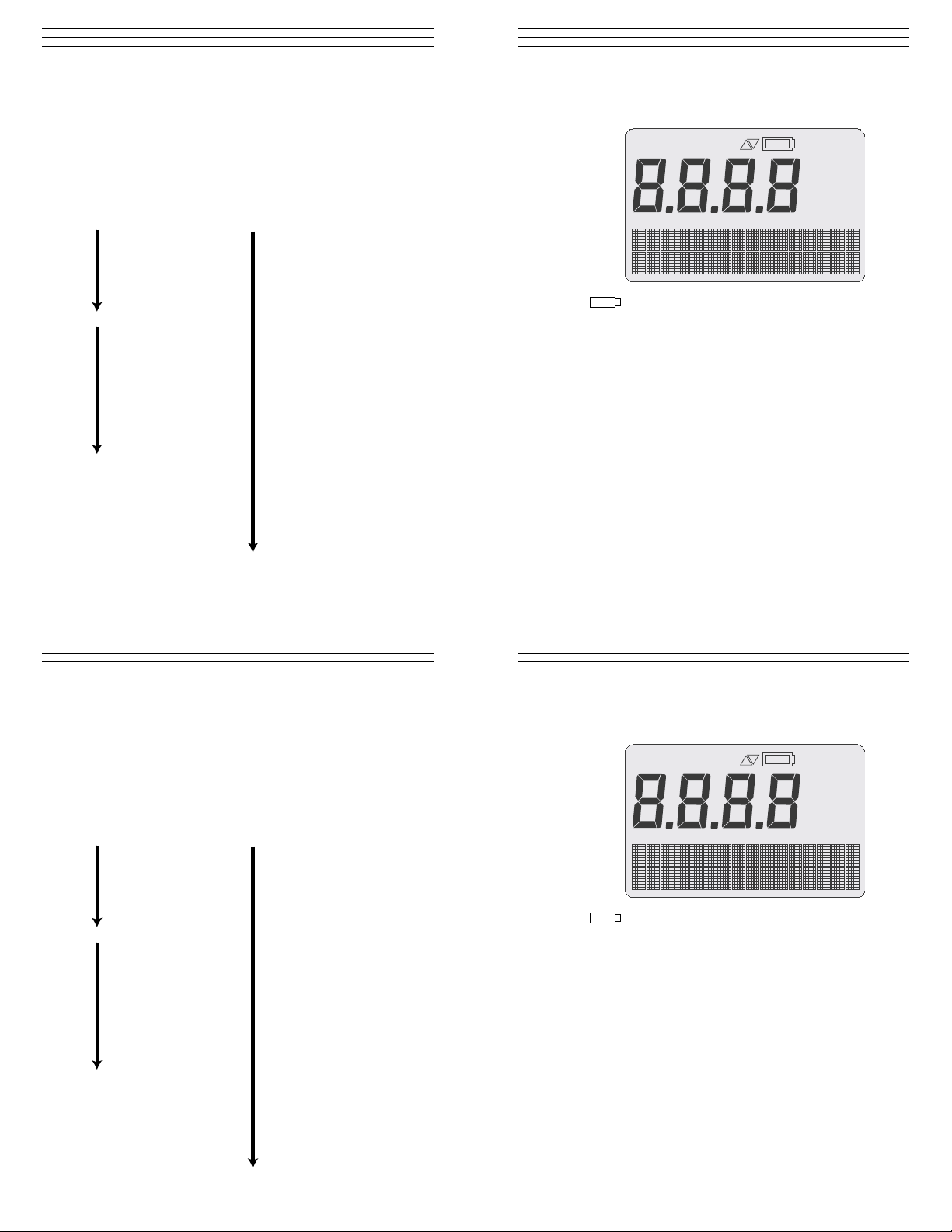
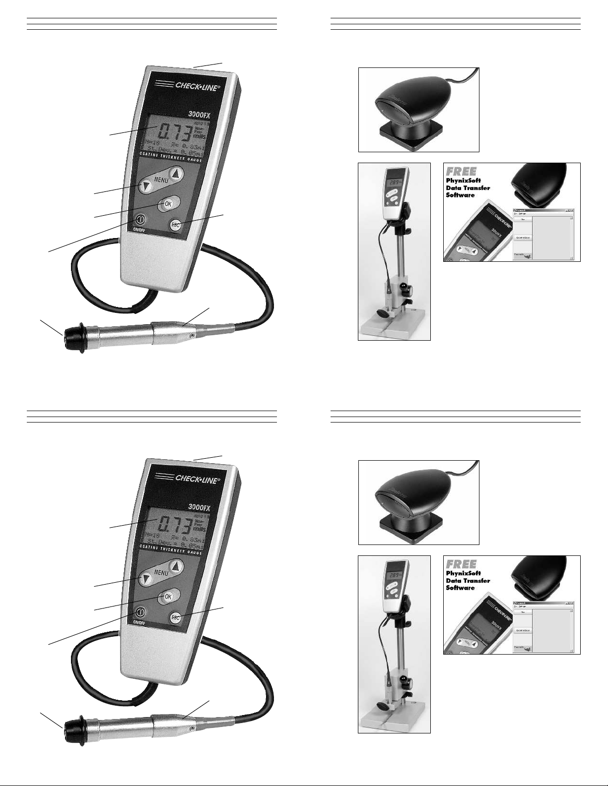
2.1 Display
If this symbol flashes, the batteries have to be
changed, see page 9.
-------- Appears if limit values are exceeded or not reached
ZERO Appears when Zero calibration is complete.
If flashing: ZERO setting begun but not completed.
CAL Appears when Foil calibration is complete.
If flashing: CAL setting begun but not completed.
LIMIT Appears if Limit values have been set.
If flashing: LIMIT setting begun but not completed.
AUTO FN Appears when automatic ferrous / non-ferrous
measuring mode is active.
Ferr Appears when ferrous measuring mode is active.
Non-Ferr Appears when non-ferrous measuring mode is active.
µm All measured values given in µm unit.
mils All measured values given in mils unit.
- 26 -
APPENDIX: DIAG RAM OF MEN U ST R UCTU R E
After turning on the instrument, press ▲ or ▼ repeatedly to move to
the desired main section (Calibration, for example). Next, press OK
to access the second level subsections within the main section. Press
▼ to scroll through the second level subsections and OK to select
one. Use the same technique of pressing ▲ or ▼ and OK to access
third level subsections; use ESC to move back to the next higher
level up to the - - - - screen, delete the last reading immediately after
taking it and interrupt a setting action.
- 26 -
- 3 -
2.0 OVERVIEW
2.1 Display
If this symbol flashes, the batteries have to be
changed, see page 9.
-------- Appears if limit values are exceeded or not reached
ZERO Appears when Zero calibration is complete.
If flashing: ZERO setting begun but not completed.
CAL Appears when Foil calibration is complete.
If flashing: CAL setting begun but not completed.
LIMIT Appears if Limit values have been set.
If flashing: LIMIT setting begun but not completed.
AUTO FN Appears when automatic ferrous / non-ferrous
measuring mode is active.
Ferr Appears when ferrous measuring mode is active.
Non-Ferr Appears when non-ferrous measuring mode is active.
µm All measured values given in µm unit.
mils All measured values given in mils unit.
- 3 -
Page 4
2.2 Gauge
C
12.0 OPTIONAL ACCESSORIES
A
B
Infrared Adapter
H
G
2.2 Gauge
D
E
Data Transfer Software
F
Test Stand
- 4 - - 25 -
12.0 OPTIONAL ACCESSORIES
A
B
Infrared Adapter
C
D
H
E
Data Transfer Software
G
F
Test Stand
- 4 - - 25 -
Page 5

11.0 RESOLUTI ON TABLE
Mils
00.00 – 9.99 mils 0.01 mils
10.00 – 24.98 mils 0.02 mils
25.00 – 49.95 mils 0.05 mils
50.00 – 60 mils 0.1 mils
Microns (µm)
000.0 – 999 µm 0.1 µm
100.0 – 249.8 µm 0.2 µm
250.0 – 499.5 µm 0.5 µm
500.0 – 999.0 µm 1.0 µm
1,000 – 1500 µm 0.002mm
A IR Sensor Transmits stored measurement data to a PC or printer
B LED Screen Displays numerical data & operator prompts
C ▲ ▼ Keys Use to:
D OK Key Use to:
E ESC Key Use to:
F Probe Place on test sample at a right angle to take
G Measurement Must be in contact with test sample for measurement
Sensor data to be recorded
H Power Switch Turns the gauge on and off
equipped with an infrared adapter
1. Scroll through main menu
2. Set calibration
3. Set zero offset
4 Set limit alerts
1. Confirm menu selection
2. Complete setting an action
1. Move back to next higher menu level
2. Delete last reading (immediately after recording it)
3. Delete of statistics & stored readings
4. Exit calibration, zero offset and limit alert setting
procedures
measurement.
0
11.0 RESOLUTI ON TABLE
Mils
00.00 – 9.99 mils 0.01 mils
10.00 – 24.98 mils 0.02 mils
25.00 – 49.95 mils 0.05 mils
50.00 – 60 mils 0.1 mils
Microns (µm)
000.0 – 999 µm 0.1 µm
100.0 – 249.8 µm 0.2 µm
250.0 – 499.5 µm 0.5 µm
500.0 – 999.0 µm 1.0 µm
1,000 – 1500 µm 0.002mm
- 24 -
- 5 -
A IR Sensor Transmits stored measurement data to a PC or printer
B LED Screen Displays numerical data & operator prompts
C ▲ ▼ Keys Use to:
D OK Key Use to:
E ESC Key Use to:
F Probe Place on test sample at a right angle to take
G Measurement Must be in contact with test sample for measurement
Sensor data to be recorded
H Power Switch Turns the gauge on and off
equipped with an infrared adapter
1. Scroll through main menu
2. Set calibration
3. Set zero offset
4 Set limit alerts
1. Confirm menu selection
2. Complete setting an action
1. Move back to next higher menu level
2. Delete last reading (immediately after recording it)
3. Delete of statistics & stored readings
4. Exit calibration, zero offset and limit alert setting
procedures
measurement.
0
- 24 -
- 5 -
Page 6

2.3 Complete Kit
3000 Series gauges are supplied as a complete kit, including:
Gauge
Probe
Zero calibration standards (Fe-stainless and/or Al)
Calibration foils (2),
Batteries (2x AA)
Operating manual
NIST calibration certificate
Carrying case
10.0 MEASURING LIMITS
Minimum Radius
for Convex Surfaces 0.12" (3mm)
Minimum Radius
for Concave Surfaces 0.2" (5mm)
Minimum Headroom 4" (100 mm)
Minimum Sample Diameter 0.2" (5mm)
Minimum Substrate Thickness - F 20 mils (0.5 mm)
Minimum Substrate Thickness - NFe 2 mils (50 µm)
- 6 -
2.3 Complete Kit
3000 Series gauges are supplied as a complete kit, including:
Gauge
Probe
Zero calibration standards (Fe-stainless and/or Al)
Calibration foils (2),
Batteries (2x AA)
Operating manual
NIST calibration certificate
Carrying case
- 23 -
10.0 MEASURING LIMITS
Minimum Radius
for Convex Surfaces 0.12" (3mm)
Minimum Radius
for Concave Surfaces 0.2" (5mm)
Minimum Headroom 4" (100 mm)
Minimum Sample Diameter 0.2" (5mm)
Minimum Substrate Thickness - F 20 mils (0.5 mm)
Minimum Substrate Thickness - NFe 2 mils (50 µm)
- 6 -
- 23 -
Page 7

9.0 SPECIFICATIONS
3.0 BASIC PROCEDURES
Range 0 – 60.00 mils (0 - 1500 µm)
Accuracy ±(0.04 mils / 1µm + 1% of reading)
Display Back-lit, 4-digit alphanumeric, digit height
0.4" (10mm)
Minimum
Measuring Area 0.2" x 0.2" (5mm x 5mm)
Minimum
Curvature Radius concave: 0.2" (5mm), convex: 0.12" (3mm)
Minimum
Substrate Thickness 20 mils (0.5 mm)
Calibration Factory calibration, zero calibration, foil
calibration,
Off-set function: addition or subtraction of a
constant value
Memory 80 readings
Statistics Program Number of readings, mean value, standard
deviation, maximum and minimum reading of
max. 10,000 readings
Set Limits Adjustable selectable with acoustic alarm
Data Output Infrared IrDA standard
Operating Temp. 32 °F to 122 °F (0 °C to 50 °C )
Surface Temp. 5 °F to 140 °F (-15 °C to 60 °C )
Storage Temp. -4 °F to 140 °F (-20 °C to +60 °C)
Power 2 AA 1.5V
Dimensions 5.6" x 2.5" x 1.2" (140mm x 562mm x 30mm)
Weight 7 oz (200 g) — gauge + probe
Protection Class IP 52 (proof against dust and dripping water)
Standards DIN, ISO, ASTM, BS
3.1 Turning Power ON and OFF
To turn the gauge on, press and hold the power switch
(item H, page 4) for two seconds, until the chime sounds. The
start screen appears briefly, followed by - - - -. The gauge is
now ready to use.
To turn the gauge off, press and hold the power switch
(item H, page 4) for two seconds, until the chime sounds.
Auto Power Off / Permanent On modes
When in the automatic power-off mode, the gauge will
automatically turn itself off after 90 seconds of non-use.
In the permanent on mode, the gauge will remain on continuously, even during extended periods of non-use. To switch
between modes:
1. Press the ▼ key repeatedly until Options shows on the
display.
2. Press OK
3. Press the ▼ key repeatedly until Switch Off Mode shows
on the display.
4. Press OK
5. Press the ▼ key to select either permanent on or auto switch
off.
6. Press OK to confirm your selection.
NOTE: To cancel a selection and exit from the menu
subsection press ESC.
- 22 -
9.0 SPECIFICATIONS
Range 0 – 60.00 mils (0 - 1500 µm)
Accuracy ±(0.04 mils / 1µm + 1% of reading)
Display Back-lit, 4-digit alphanumeric, digit height
0.4" (10mm)
Minimum
Measuring Area 0.2" x 0.2" (5mm x 5mm)
Minimum
Curvature Radius concave: 0.2" (5mm), convex: 0.12" (3mm)
Minimum
Substrate Thickness 20 mils (0.5 mm)
Calibration Factory calibration, zero calibration, foil
calibration,
Off-set function: addition or subtraction of a
constant value
Memory 80 readings
Statistics Program Number of readings, mean value, standard
deviation, maximum and minimum reading of
max. 10,000 readings
Set Limits Adjustable selectable with acoustic alarm
Data Output Infrared IrDA standard
Operating Temp. 32 °F to 122 °F (0 °C to 50 °C )
Surface Temp. 5 °F to 140 °F (-15 °C to 60 °C )
Storage Temp. -4 °F to 140 °F (-20 °C to +60 °C)
Power 2 AA 1.5V
Dimensions 5.6" x 2.5" x 1.2" (140mm x 562mm x 30mm)
Weight 7 oz (200 g) — gauge + probe
Protection Class IP 52 (proof against dust and dripping water)
Standards DIN, ISO, ASTM, BS
- 7 -
3.0 BASIC PROCEDURES
3.1 Turning Power ON and OFF
To turn the gauge on, press and hold the power switch
(item H, page 4) for two seconds, until the chime sounds. The
start screen appears briefly, followed by - - - -. The gauge is
now ready to use.
To turn the gauge off, press and hold the power switch
(item H, page 4) for two seconds, until the chime sounds.
Auto Power Off / Permanent On modes
When in the automatic power-off mode, the gauge will
automatically turn itself off after 90 seconds of non-use.
In the permanent on mode, the gauge will remain on continuously, even during extended periods of non-use. To switch
between modes:
1. Press the ▼ key repeatedly until Options shows on the
display.
2. Press OK
3. Press the ▼ key repeatedly until Switch Off Mode shows
on the display.
4. Press OK
5. Press the ▼ key to select either permanent on or auto switch
off.
6. Press OK to confirm your selection.
NOTE: To cancel a selection and exit from the menu
subsection press ESC.
- 22 -
- 7 -
Page 8

3.2 Selecting Units of Measure (µm-metric or inch-mils)
1. Press ▼ repeatedly until display shows Options.
2. Press OK. The display shows Measuring Unit.
3. Press OK. The display shows µm unit
4. Press OK to confirm µm as unit of measurement OR
5. Press ▼ again. The display shows mils unit.
6. Press OK to confirm mils as unit of measurement
The selected unit of measure (mils or µm) will appear on the
display, followed by the start screen - - - -.
3.3 Backlight
3000FX Series gauges equipped with a backlight function
to improve the readability of the display in certain lighting
conditions. The operator can select permanent on, 3-second on
(after each measurement) and off:
1. Press the ▼ key until Options shows on the display.
2. Press OK.
3. Press the ▼ key to scroll to the desired backlight state.
4. Press OK to confirm your selection.
The selected backlight state will appear on the display briefly,
followed by the start screen - - - -.
3.4 Beeper
To turn the audible signal on and off:
1. Press the ▼ key until Options shows on the display.
2. Press the OK key.
3. Press the ▼ key until Beeper shows on the display.
4. Press OK.
8.0 ERROR MESSAGES
Faults or malfunctions identified by the instrument are indicated by
an error message appearing on the display:
Batteries are empty:
Please insert new batteries.
Probe is too close to metal:
The probe was too close to the metal during switch-on. Hold the
probe free in the air and then switch the instrument on.
Magnetic interference fields:
Close to the probe are too strong magnetic interference fields (e.g.
transformers, PC-display screens).
Probe defective:
If this error message appears, please send the instrument to your
supplier or to the manufacturer for repair.
Other errors:
If the following errors appear on your instrument
• Instrument does not allow any further measurements
• Illogical display values
a total reset usually helps (see page 9)
- 8 -
3.2 Selecting Units of Measure (µm-metric or inch-mils)
1. Press ▼ repeatedly until display shows Options.
2. Press OK. The display shows Measuring Unit.
3. Press OK. The display shows µm unit
4. Press OK to confirm µm as unit of measurement OR
5. Press ▼ again. The display shows mils unit.
6. Press OK to confirm mils as unit of measurement
The selected unit of measure (mils or µm) will appear on the
display, followed by the start screen - - - -.
3.3 Backlight
3000FX Series gauges equipped with a backlight function
to improve the readability of the display in certain lighting
conditions. The operator can select permanent on, 3-second on
(after each measurement) and off:
1. Press the ▼ key until Options shows on the display.
2. Press OK.
3. Press the ▼ key to scroll to the desired backlight state.
4. Press OK to confirm your selection.
The selected backlight state will appear on the display briefly,
followed by the start screen - - - -.
3.4 Beeper
To turn the audible signal on and off:
1. Press the ▼ key until Options shows on the display.
2. Press the OK key.
3. Press the ▼ key until Beeper shows on the display.
4. Press OK.
- 21 -
8.0 ERROR MESSAGES
Faults or malfunctions identified by the instrument are indicated by
an error message appearing on the display:
Batteries are empty:
Please insert new batteries.
Probe is too close to metal:
The probe was too close to the metal during switch-on. Hold the
probe free in the air and then switch the instrument on.
Magnetic interference fields:
Close to the probe are too strong magnetic interference fields (e.g.
transformers, PC-display screens).
Probe defective:
If this error message appears, please send the instrument to your
supplier or to the manufacturer for repair.
Other errors:
If the following errors appear on your instrument
• Instrument does not allow any further measurements
• Illogical display values
a total reset usually helps (see page 9)
- 8 -
- 21 -
Page 9

• Do not expose the window of the infrared adapter to direct solar
radiation.
• Do not operate any filament and halogen lamps in the immediate
vicinity of the adapter. The distance between adapter and lamp
should be more than 1 meter.
• The infrared windows of the test instrument and of the adapter
must be parallel and facing each other at a distance of around
30 cm to 50 cm.
After pressing OK to start infrared data transmission, keep the
gauge´s infrared window pointed at the IR adapter as long as the
green LED is lit.
5. Press the ▼ key to select the on or off states.
6. Press OK to confirm your selection
3.5 Manually Setting Measurement Mode (DCFN only)
In some cases, especially with varnish applied to zinc on steel,
it is advisable to manually set the measuring mode—F mode
(Ferrous) for measurements on steel/iron, N mode (NonFerrous) for measurements on non-ferrous metals.
1. Press ▼ repeatedly until display shows Options.
2. Press OK. Measuring Unit appears on the display.
3. Press ▼ repeatedly until Measuring Mode appears.
4. Press OK. Auto FN Identifications appears.
5. Press ▼ repeatedly until either Ferrous (F) or
Non-Ferrous (N) or Auto FN appears on the display.
6. Press OK to confirm the measurement mode that you want
to activate. The display shows - - - - and either Auto FN
or Ferr or Non-Ferr. See diagram of dsiplay on page 3.
3.6 Total Reset To Factory Defaults
This procedure deletes all single and statistical values. It also
deletes set calibration values and optional items and resets the
gauge to the factory default.
1. Switch off the gauge
2. Press and hold the ESC key (item E, page 4). At the
same time turn the power back on.
3. An acoustic signal will sound and all factory default
settings are restored.
4. Release both keys and the gauge will restart with all
factory default settings restored.
- 20 -
• Do not expose the window of the infrared adapter to direct solar
radiation.
• Do not operate any filament and halogen lamps in the immediate
vicinity of the adapter. The distance between adapter and lamp
should be more than 1 meter.
• The infrared windows of the test instrument and of the adapter
must be parallel and facing each other at a distance of around
30 cm to 50 cm.
After pressing OK to start infrared data transmission, keep the
gauge´s infrared window pointed at the IR adapter as long as the
green LED is lit.
- 9 -
5. Press the ▼ key to select the on or off states.
6. Press OK to confirm your selection
3.5 Manually Setting Measurement Mode (DCFN only)
In some cases, especially with varnish applied to zinc on steel,
it is advisable to manually set the measuring mode—F mode
(Ferrous) for measurements on steel/iron, N mode (NonFerrous) for measurements on non-ferrous metals.
1. Press ▼ repeatedly until display shows Options.
2. Press OK. Measuring Unit appears on the display.
3. Press ▼ repeatedly until Measuring Mode appears.
4. Press OK. Auto FN Identifications appears.
5. Press ▼ repeatedly until either Ferrous (F) or
Non-Ferrous (N) or Auto FN appears on the display.
6. Press OK to confirm the measurement mode that you want
to activate. The display shows - - - - and either Auto FN
or Ferr or Non-Ferr. See diagram of dsiplay on page 3.
3.6 Total Reset To Factory Defaults
This procedure deletes all single and statistical values. It also
deletes set calibration values and optional items and resets the
gauge to the factory default.
1. Switch off the gauge
2. Press and hold the ESC key (item E, page 4). At the
same time turn the power back on.
3. An acoustic signal will sound and all factory default
settings are restored.
4. Release both keys and the gauge will restart with all
factory default settings restored.
- 20 -
- 9 -
Page 10

3.7 Battery Replacement
N
F
µ
A
MIT
NoNo
FeFer
µ
AUTAUTO
ITIMIT
3000FX gauges use two AA
alkaline or rechargeable batteries.
When battery power becomes low
the Battery Indicator will flash.
The gauge will continue to operate,
but batteries should be replaced as soon as possible When
battery power is depleted, the Battery Indicator remains on
continuously, indicating that less than 60 seconds of power
remain shut down.
Replacing batteries
1. Turn the gauge over. Slide the
release switch down to unlock
the battery compartment.
2. Carefully pull the battery
compartment cover away from
the gauge.
3. Insert new batteries, following
the polarity diagram on the inside
of the battery compartment.
4. Replace the battery compartment
cover by inserting the hooks at the
bottom edge, then pushing the
cover forward until it snaps into
position.
5. Slide the release switch up to lock the cover in place.
NOTE: Battery exchange should be accomplished within
20 seconds to preserve saved measurement data.
7.0 DATA TRANSFER
For data transfer from a 3000FX series gauge to a PC you must not
use a possible enclosed drive disc. For the infrared data transmission
from the gauge to a printer or to a PC, the following three requirements must be met:
1. The infrared adapter (accessory part) must be connected to the
printer or PC. The infrared window of the gauge and of the adapter
must be parallel and face each other at a distance of approximately
12” to 20” (30cm to 50cm) for the data transmission.
2. The serial interface parameters of the PC and the printer must be
set as follows:
Baud rate: 9600
Data bits: 8
Stop bit: 1
Parity: none
Handshake non
3. A data transmission program must be installed for the data
transmission to a PC.
General information regarding the infrared data transfer using
3000FX
It is of special importance with reference to the infrared data transfer
that the transmitted light-induced pulses can be perfectly received and
evaluated. The infrared adapter receiving the light-induced pulses
must therefore be protected from any external interferences. For this
reason, please observe the following:
- 10 -
3.7 Battery Replacement
3000FX gauges use two AA
alkaline or rechargeable batteries.
When battery power becomes low
the Battery Indicator will flash.
The gauge will continue to operate,
but batteries should be replaced as soon as possible When
battery power is depleted, the Battery Indicator remains on
continuously, indicating that less than 60 seconds of power
remain shut down.
Replacing batteries
1. Turn the gauge over. Slide the
release switch down to unlock
the battery compartment.
2. Carefully pull the battery
compartment cover away from
the gauge.
3. Insert new batteries, following
the polarity diagram on the inside
of the battery compartment.
4. Replace the battery compartment
cover by inserting the hooks at the
bottom edge, then pushing the
cover forward until it snaps into
position.
5. Slide the release switch up to lock the cover in place.
NOTE: Battery exchange should be accomplished within
20 seconds to preserve saved measurement data.
- 19 -
7.0 DATA TRANSFER
For data transfer from a 3000FX series gauge to a PC you must not
use a possible enclosed drive disc. For the infrared data transmission
from the gauge to a printer or to a PC, the following three requirements must be met:
1. The infrared adapter (accessory part) must be connected to the
printer or PC. The infrared window of the gauge and of the adapter
must be parallel and face each other at a distance of approximately
12” to 20” (30cm to 50cm) for the data transmission.
2. The serial interface parameters of the PC and the printer must be
set as follows:
Baud rate: 9600
Data bits: 8
Stop bit: 1
Parity: none
Handshake non
3. A data transmission program must be installed for the data
transmission to a PC.
General information regarding the infrared data transfer using
3000FX
It is of special importance with reference to the infrared data transfer
that the transmitted light-induced pulses can be perfectly received and
evaluated. The infrared adapter receiving the light-induced pulses
must therefore be protected from any external interferences. For this
reason, please observe the following:
- 10 -
- 19 -
Page 11

To continue measuring, press ESC repeatedly until the start
screen with the four dashes - - - - is displayed.
To print statistical values:
1. Press ▼ repeatedly until Statistics appears n display.
2. Press OK. Printout Of Statistics appears.
3. Point instrument with the IR transmitter (top end face)
towards the IR adapter installed on the printer. The distance
should be approx. 12” to 20” (30cm to 50cm).
4. Press OK. The data are transmitted, and Printing... will
briefly appear, followed by the start screen with the four
dashes - - - -.
To continue measuring, press ESC repeatedly until the start
screen with the four dashes - - - - is displayed again.
6.4 Deletion of statistical values and of single values
1. Press ▼ repeatedly until Statistics appears on display.
2. Press OK. Printout Of Statistics appears
3. Press ▼ repeatedly until Deletion Of Statistics appears
4. Press OK. The statistical values with the single values are
deleted. Statistics deleted will briefly appear on the display,
then the start screen with the four dashes - - - - .
Quick deletion of statistics and stored readings
1. Press ESC repeatedly until the start screen with the four
dashes - - - - is again displayed.
2. Press ESC until Deleted Statistic? appears on the display.
3. Press ESC again. Statistics Deleted will briefly appear,
then the start screen with the four dashes - - - -.
Using Rechargeable batteries
When using rechargeable batteries, the battery symbol always
flashes, because rechargeable batteries provide a lower voltage
than non-rechargeable batteries. To eliminate this situation:
1. Press ▼ repeatedly until Options appears on the display.
2. Press OK.
3. Press ▼ until Power Supply appears on the display.
4. Press OK.
5. Press ▼ until Rechargeable Batteries appears on the
display.
6. Press OK.
Supply with Rechargeable Batt appears briefly on the screen,
followed by - - - . The procedure is complete.
- 18 -
To continue measuring, press ESC repeatedly until the start
screen with the four dashes - - - - is displayed.
To print statistical values:
1. Press ▼ repeatedly until Statistics appears n display.
2. Press OK. Printout Of Statistics appears.
3. Point instrument with the IR transmitter (top end face)
towards the IR adapter installed on the printer. The distance
should be approx. 12” to 20” (30cm to 50cm).
4. Press OK. The data are transmitted, and Printing... will
briefly appear, followed by the start screen with the four
dashes - - - -.
To continue measuring, press ESC repeatedly until the start
screen with the four dashes - - - - is displayed again.
6.4 Deletion of statistical values and of single values
1. Press ▼ repeatedly until Statistics appears on display.
2. Press OK. Printout Of Statistics appears
3. Press ▼ repeatedly until Deletion Of Statistics appears
4. Press OK. The statistical values with the single values are
deleted. Statistics deleted will briefly appear on the display,
then the start screen with the four dashes - - - - .
Quick deletion of statistics and stored readings
1. Press ESC repeatedly until the start screen with the four
dashes - - - - is again displayed.
2. Press ESC until Deleted Statistic? appears on the display.
3. Press ESC again. Statistics Deleted will briefly appear,
then the start screen with the four dashes - - - -.
- 11 -
Using Rechargeable batteries
When using rechargeable batteries, the battery symbol always
flashes, because rechargeable batteries provide a lower voltage
than non-rechargeable batteries. To eliminate this situation:
1. Press ▼ repeatedly until Options appears on the display.
2. Press OK.
3. Press ▼ until Power Supply appears on the display.
4. Press OK.
5. Press ▼ until Rechargeable Batteries appears on the
display.
6. Press OK.
Supply with Rechargeable Batt appears briefly on the screen,
followed by - - - . The procedure is complete.
- 18 -
- 11 -
Page 12

4.0 CALIBRATION
4.1 Measuring Using Factory (Works) Calibration
1. Press ▼. Calibration appears on the display.
2. Press OK. Zero Setting appears on the display.
3. Press ▼ repeatedly until Delete Calibration appears.
4. Press OK. Works Calibration Activated appears
briefly, then the start screen with - - - -. You can now
carry out the measurement.
4.2 One-point calibration (zero procedure)
This procedure requires an uncoated test object having
similar dimensions and material properties to those of the
coated object to be measured.
1. Press ▼. Calibration appears on the display.
2. Press OK. Zero Setting appears.
3. Place the Measuring Sensor (item G, page 4) on the test
object at a right angle. Press gently and hold until chime
sounds, then lift up. Repeat several times.
4. Press OK. Zero has been set appears briefly on the display,
followed by the start screen with the four dashes - - - -.
You can now carry out the measurement.
4.3 Two-point calibration (using calibration foil)
As with Zero setting, this procedure requires an uncoated test
object having similar dimensions as the coated object that will
be measured. Choose a calibration foil that is closest to the
expected coating layer thickness.
3. Press ▼ until Display of Single Values appears.
To continue measuring, press ESC repeatedly until the start
screen with the four dashes - - - - is displayed.
To print single values:
1. Press ▼ repeatedly until Statistics appears on display.
2. Press OK. Printout Of Statistics appears
3. Press ▼ repeatedly until Printout of Single Values
appears
4. Point instrument with the IR transmitter (top end edge)
towards the IR adapter installed on the printer. The distance
should be approx. 12” to 20” (30cm to 50cm)
5. Press OK. The data are transmitted, and Printing... will
briefly appear, followed by the start screen with the four
dashes - - - -.
To continue measuring, press ESCrepeatedly until the start
screen with the four dashes - - - - is displayed again.
6.3 Display and print statistical values
To display statistical values:
1. Press ▼ repeatedly until Statistics appears on display.
2. Press OK. Printout Of Statistics appears.
3. Press ▼ repeatedly until Display Of Statistics appears.
4. Press OK repeatedly. Each time OK is pressed, a different
statistical value will be displayed in this order: N, x, s,
and then N, Max, Min. At the conclusion, Display of
Statistics appears again and the sequence of statistics
displayed will repeat.
- 12 -
4.0 CALIBRATION
4.1 Measuring Using Factory (Works) Calibration
1. Press ▼. Calibration appears on the display.
2. Press OK. Zero Setting appears on the display.
3. Press ▼ repeatedly until Delete Calibration appears.
4. Press OK. Works Calibration Activated appears
briefly, then the start screen with - - - -. You can now
carry out the measurement.
4.2 One-point calibration (zero procedure)
This procedure requires an uncoated test object having
similar dimensions and material properties to those of the
coated object to be measured.
1. Press ▼. Calibration appears on the display.
2. Press OK. Zero Setting appears.
3. Place the Measuring Sensor (item G, page 4) on the test
object at a right angle. Press gently and hold until chime
sounds, then lift up. Repeat several times.
4. Press OK. Zero has been set appears briefly on the display,
followed by the start screen with the four dashes - - - -.
You can now carry out the measurement.
4.3 Two-point calibration (using calibration foil)
As with Zero setting, this procedure requires an uncoated test
object having similar dimensions as the coated object that will
be measured. Choose a calibration foil that is closest to the
expected coating layer thickness.
- 17 -
3. Press ▼ until Display of Single Values appears.
To continue measuring, press ESC repeatedly until the start
screen with the four dashes - - - - is displayed.
To print single values:
1. Press ▼ repeatedly until Statistics appears on display.
2. Press OK. Printout Of Statistics appears
3. Press ▼ repeatedly until Printout of Single Values
appears
4. Point instrument with the IR transmitter (top end edge)
towards the IR adapter installed on the printer. The distance
should be approx. 12” to 20” (30cm to 50cm)
5. Press OK. The data are transmitted, and Printing... will
briefly appear, followed by the start screen with the four
dashes - - - -.
To continue measuring, press ESCrepeatedly until the start
screen with the four dashes - - - - is displayed again.
6.3 Display and print statistical values
To display statistical values:
1. Press ▼ repeatedly until Statistics appears on display.
2. Press OK. Printout Of Statistics appears.
3. Press ▼ repeatedly until Display Of Statistics appears.
4. Press OK repeatedly. Each time OK is pressed, a different
statistical value will be displayed in this order: N, x, s,
and then N, Max, Min. At the conclusion, Display of
Statistics appears again and the sequence of statistics
displayed will repeat.
- 12 -
- 17 -
Page 13

6.0 MANAGING SINGLE AND STATIST ICAL VALUES
The 3000FX gauge is provided with
online statistics. The statistical values
are re-calculated and displayed in the
two bottom lines after everymeasurement.The statistical values calculated
by the 3000FX gauges are:
N: Number of measured values
x: Average of measured values
s: Standard deviation
Max: Maximum single value of the measurement series
Min: Minimum single value of the measurement series
Note: The DCFN-3000FX can store a total of 80 readings combining the F-mode N-mode, not 80 readings in each mode (160 total).
6.1 Selecting which statistical values will be displayed.
1. Press ▼ repeatedly until Options appears on the display.
2. Press OK.
3. Press ▼ Until On-Line Statistics appears on the display.
4. Press OK.
5. Press ▼ to select either Maximum and Minimum or
Mean and Std Deviation for display.
6. Press OK to confirm your selection.
6.2 Displaying and printing single values
To display single values:
1. Press ▼ repeatedly until Statistics appears on display.
2. Press OK. Printout of statistics appears on the display.
1. Carry out a zero procedure (see section 4.2).
2. Press ▼. Calibration appears on the display.
3. Press OK. Zero Setting appears
4. Press ▼ again. Foil Calibration appears.
5. Press OK. Place probe on foil. Standard appears.
6. Put the measurement foil on the uncoated test object and
place the probe repeatedly on the foil.
7. Press ▼ or ▲ until the displayed value agrees with the
thickness value of the calibration foil.
8. Press OK. Calibration has been set appears briefly, then
the start screen with four dashes - - - - appears.
You can now carry out the measurement
4.4 Zero Offset
In this menu item, a constant positive or negative value can
be set. This value is automatically added to the measured value
or subtracted from the measured value every time a measurement is carried out. The display then shows the addition or the
difference. Moreover, the zero offset setting is always indicated
below in the display as a reminder.
This measuring mode is useful when determining the upper
coating layer of a multi-layer system. If the lower layer(s)
is (are) known and show an adequately uniform thickness,
the coating thickness of this (these) layer(s) can be set as a
negative offset value. The display then only shows the
thickness of the top layer.
When measuring coated rough metal surfaces, this mode can
also be selected. In this case, the roughness effect, which is
determined on the basis of the uncoated rough metal surface, is
- 16 -
6.0 MANAGING SINGLE AND STATIST ICAL VALUES
The 3000FX gauge is provided with
online statistics. The statistical values
are re-calculated and displayed in the
two bottom lines after everymeasurement.The statistical values calculated
by the 3000FX gauges are:
N: Number of measured values
x: Average of measured values
s: Standard deviation
Max: Maximum single value of the measurement series
Min: Minimum single value of the measurement series
Note: The DCFN-3000FX can store a total of 80 readings combining the F-mode N-mode, not 80 readings in each mode (160 total).
6.1 Selecting which statistical values will be displayed.
1. Press ▼ repeatedly until Options appears on the display.
2. Press OK.
3. Press ▼ Until On-Line Statistics appears on the display.
4. Press OK.
5. Press ▼ to select either Maximum and Minimum or
Mean and Std Deviation for display.
6. Press OK to confirm your selection.
6.2 Displaying and printing single values
To display single values:
1. Press ▼ repeatedly until Statistics appears on display.
2. Press OK. Printout of statistics appears on the display.
- 13 -
1. Carry out a zero procedure (see section 4.2).
2. Press ▼. Calibration appears on the display.
3. Press OK. Zero Setting appears
4. Press ▼ again. Foil Calibration appears.
5. Press OK. Place probe on foil. Standard appears.
6. Put the measurement foil on the uncoated test object and
place the probe repeatedly on the foil.
7. Press ▼ or ▲ until the displayed value agrees with the
thickness value of the calibration foil.
8. Press OK. Calibration has been set appears briefly, then
the start screen with four dashes - - - - appears.
You can now carry out the measurement
4.4 Zero Offset
In this menu item, a constant positive or negative value can
be set. This value is automatically added to the measured value
or subtracted from the measured value every time a measurement is carried out. The display then shows the addition or the
difference. Moreover, the zero offset setting is always indicated
below in the display as a reminder.
This measuring mode is useful when determining the upper
coating layer of a multi-layer system. If the lower layer(s)
is (are) known and show an adequately uniform thickness,
the coating thickness of this (these) layer(s) can be set as a
negative offset value. The display then only shows the
thickness of the top layer.
When measuring coated rough metal surfaces, this mode can
also be selected. In this case, the roughness effect, which is
determined on the basis of the uncoated rough metal surface, is
- 16 -
- 13 -
Page 14

set as a negative offset value. The instrument will then display
the coating thickness above the peaks of the rough surface.
Setting Zero Offset Value
1. Press ▼. Calibration appears on the display’
2. Press OK. Zero Setting appears on the display
3. Press ▼ twice. Zero Offset appears on the display.
4. Press OK. Offsets appears on the display.
5. Press OK. Set Offset Value appears on the display.
6. Press ▼ or ▲ repeatedly until the required offset value
appears on the display.
7. Press OK. Offset Has Been Set appears on the display
briefly, followed by the start display with - - - -.
Deleting Zero Offset Value
1. Press ▼ Calibration appears on the display
2. Press OK. Zero Setting appears on the display
3. Press ▼ twice. Zero Offset appears on the display
4. Press OK. Setting of Offset appears on the display
5. Press ▼. Deletion of Offset appears on the display
6. Press OK. Offset Deleted appears briefly, followed by
the start display with the four dashes - - - -.
5.0 SETTING AUDIBLE LIM IT ALERTS
To monitor your measured values, you can set an upper and a lower
limit value. This setting is useful during the measurement, for the
evaluation of the measured values later when displaying the single
values or for the printout of measured values If the limit value is
exceeded or if it's not reached, an audio signal will sound, and a
warning note will appear on the display (_ or _).
Setting
1. Press ▼ repeatedly until Limits appears on the display
2. Press OK. Limits Setting appears on the display.
3. Press OK again. Set Lower Limit appears.
4. Press ▼ or ▲ repeatedly until the desired lower limit value
appears on the display.
5. Press OK. Set Upper Limit appears on the display.
6. Press ▼ or ▲ repeatedly until the desired upper limit value
appears on the display.
7. Press OK. Limits have been set will appear briefly, then the
start screen with - - - -.
Deleting
1. Press ▼ repeatedly until Limit s appears on the display.
2. Press OK. Limits Setting appears
3. Press ▼ until Deletion of Limits appears
4. Press OK. Limits Deleted appears briefly, followed by the
start screen with - - - -.
- 14 -
set as a negative offset value. The instrument will then display
the coating thickness above the peaks of the rough surface.
Setting Zero Offset Value
1. Press ▼. Calibration appears on the display’
2. Press OK. Zero Setting appears on the display
3. Press ▼ twice. Zero Offset appears on the display.
4. Press OK. Offsets appears on the display.
5. Press OK. Set Offset Value appears on the display.
6. Press ▼ or ▲ repeatedly until the required offset value
appears on the display.
7. Press OK. Offset Has Been Set appears on the display
briefly, followed by the start display with - - - -.
Deleting Zero Offset Value
1. Press ▼ Calibration appears on the display
2. Press OK. Zero Setting appears on the display
3. Press ▼ twice. Zero Offset appears on the display
4. Press OK. Setting of Offset appears on the display
5. Press ▼. Deletion of Offset appears on the display
6. Press OK. Offset Deleted appears briefly, followed by
the start display with the four dashes - - - -.
- 15 -
5.0 SETTING AUDIBLE LIM IT ALERTS
To monitor your measured values, you can set an upper and a lower
limit value. This setting is useful during the measurement, for the
evaluation of the measured values later when displaying the single
values or for the printout of measured values If the limit value is
exceeded or if it's not reached, an audio signal will sound, and a
warning note will appear on the display (_ or _).
Setting
1. Press ▼ repeatedly until Limits appears on the display
2. Press OK. Limits Setting appears on the display.
3. Press OK again. Set Lower Limit appears.
4. Press ▼ or ▲ repeatedly until the desired lower limit value
appears on the display.
5. Press OK. Set Upper Limit appears on the display.
6. Press ▼ or ▲ repeatedly until the desired upper limit value
appears on the display.
7. Press OK. Limits have been set will appear briefly, then the
start screen with - - - -.
Deleting
1. Press ▼ repeatedly until Limit s appears on the display.
2. Press OK. Limits Setting appears
3. Press ▼ until Deletion of Limits appears
4. Press OK. Limits Deleted appears briefly, followed by the
start screen with - - - -.
- 14 -
- 15 -
Page 15

OI507-FX
CHECK•LINE
BY ELECTROMATIC
Coating Thickness Gauges
DCF-3000FX, DCN-3000FX, DCFN-3000FX
®
CHECK•LINE
INSTRUMENTS
®
ELECTROMATIC
E Q U I P M E N T C O., I N C.
600 Oakland Ave., Cedarhurst, NY 11516–U.S.A.
TEL: 516-295-4300
•
FAX: 516-295-4399
www.checkline.com
Oper ati ng In str ucti on s
OI507-FX
CHECK•LINE
BY ELECTROMATIC
Coating Thickness Gauges
DCF-3000FX, DCN-3000FX, DCFN-3000FX
®
CHECK•LINE
INSTRUMENTS
®
ELECTROMATIC
E Q U I P M E N T C O., I N C.
600 Oakland Ave., Cedarhurst, NY 11516–U.S.A.
TEL: 516-295-4300
•
FAX: 516-295-4399
www.checkline.com
Oper ati ng In str ucti on s
 Loading...