

Page 1

11.0 WARRANTY
ELECTROMATIC Equipment Co., Inc. (ELECTROMATIC) warrants to the original purchaser that this product is of merchantable quality and confirms in kind and quality with the
descriptions and specifications thereof. Product failure or malfunction arising out of any
defect in workmanship or material in the product existing at the time of delivery thereof
which manifests itself within one year from the sale of such product, shall be remedied by
repair or replacement of such product, at ELECTROMATIC’s option, except where unauthorized repair, disassembly, tampering, abuse or misapplication has taken place, as determined
by ELECTROMATIC. All returns for warranty or non-warranty repairs and/or replacement
must be authorized by ELECTROMATIC, in advance, with all repacking and shipping
expenses to the address below to be borne by the purchaser.
THE FOREGOING WARRANTY IS IN LIEU OF ALL OTHER WARRANTIES,
EXPRESSED OR IMPLIED, INCLUDING BUT NOT LIMITED TO, THE WARRANTY
OF MERCHANTABILITY AND FITNESS FOR ANY PARTICULAR PURPOSE OR
APPLICATION. ELECTROMATIC SHALL NOT BE RESPONSIBLE NOR LIABLE FOR
ANY CONSEQUENTIAL DAMAGE, OF ANY KIND OR NATURE, RESULTING FROM
THE USE OF SUPPLIED EQUIPMENT, WHETHER SUCH DAMAGE OCCURS OR IS
DISCOVERED BEFORE, UPON OR AFTER REPLACEMENT OR REPAIR, AND
WHETHER OR NOT SUCH DAMAGE IS CAUSED BY MANUFACTURER’S OR SUPPLIER’S NEGLIGENCE WITHIN ONE YEAR FROM INVOICE DATE.
Some State jurisdictions or States do not allow the exclusion or limitation of incidental or
consequential damages, so the above limitation may not apply to you. The duration of any
implied warranty, including, without limitation, fitness for any particular purpose and merchantability with respect to this product, is limited to the duration of the foregoing warranty.
Some states do not allow limitations on how long an implied warranty lasts but, not withstanding, this warranty, in the absence of such limitations, shall extend for one year from the
date of invoice.
ELECTROMATIC Equipment Co., Inc.
600 Oakland Ave. Cedarhurst, NY 11516—USA
Tel: 1-800-645-4330/ Tel: 516-295-4300/ Fax: 516-295-4399
Every precaution has been taken in the preparation of this manual. Electromatic Equipment
Co., Inc., assumes no responsibility for errors or omissions. Neither is any liability assumed
for damages resulting from the use of information contained herein. Any brand or product
names mentioned herein are used for identification purposes only, and are trademarks or registered trademarks of their respective holders.
TABLE OF CONTENTS
1.0 Introduction . . . . . . . . . . . . . . . . . . . . . . . . . . . . . . . . . . . . . . . . . 02
2.0 Overview . . . . . . . . . . . . . . . . . . . . . . . . . . . . . . . . . . . . . . . . . . . . 03
2.1 Gauge
2.2 Display
2.3 Complete Kit
3.0 Basic Procedures . . . . . . . . . . . . . . . . . . . . . . . . . . . . . . . . . . . . 04
3.1 Power
3.2 Selecting Units of Measure
3.3 Manually Setting the Measure Mode (DCFN version only)
3.4 Total Reset to Factory Defaults
3.5 Battery Replacement
4.0 Taking Measurements Using Factory Calibration . . . . . . 07
5.0 Performing A ZERO Procedure (Custom Calibration) . . . 08
5.1 Checking Accuracy
5.2 Clearing a ZERO setting and restoring Factory Calibration
6.0 Online statistics Display . . . . . . . . . . . . . . . . . . . . . . . . . . . . . 10
6.1 Deleting the Statistical Values
7.0 Specifications . . . . . . . . . . . . . . . . . . . . . . . . . . . . . . . . . . . . . . . 12
8.0 Resolution Table . . . . . . . . . . . . . . . . . . . . . . . . . . . . . . . . . . . . . 13
9.0 Measuring Limits . . . . . . . . . . . . . . . . . . . . . . . . . . . . . . . . . . . . 14
10.0 Error Messages . . . . . . . . . . . . . . . . . . . . . . . . . . . . . . . . . . . . . 15
11.0 Warranty . . . . . . . . . . . . . . . . . . . . . . . . . . . . . . . . . . . . . . . . . . . . 16
16
11.0 WARRANTY
ELECTROMATIC Equipment Co., Inc. (ELECTROMATIC) warrants to the original purchaser that this product is of merchantable quality and confirms in kind and quality with the
descriptions and specifications thereof. Product failure or malfunction arising out of any
defect in workmanship or material in the product existing at the time of delivery thereof
which manifests itself within one year from the sale of such product, shall be remedied by
repair or replacement of such product, at ELECTROMATIC’s option, except where unauthorized repair, disassembly, tampering, abuse or misapplication has taken place, as determined
by ELECTROMATIC. All returns for warranty or non-warranty repairs and/or replacement
must be authorized by ELECTROMATIC, in advance, with all repacking and shipping
expenses to the address below to be borne by the purchaser.
THE FOREGOING WARRANTY IS IN LIEU OF ALL OTHER WARRANTIES,
EXPRESSED OR IMPLIED, INCLUDING BUT NOT LIMITED TO, THE WARRANTY
OF MERCHANTABILITY AND FITNESS FOR ANY PARTICULAR PURPOSE OR
APPLICATION. ELECTROMATIC SHALL NOT BE RESPONSIBLE NOR LIABLE FOR
ANY CONSEQUENTIAL DAMAGE, OF ANY KIND OR NATURE, RESULTING FROM
THE USE OF SUPPLIED EQUIPMENT, WHETHER SUCH DAMAGE OCCURS OR IS
DISCOVERED BEFORE, UPON OR AFTER REPLACEMENT OR REPAIR, AND
WHETHER OR NOT SUCH DAMAGE IS CAUSED BY MANUFACTURER’S OR SUPPLIER’S NEGLIGENCE WITHIN ONE YEAR FROM INVOICE DATE.
Some State jurisdictions or States do not allow the exclusion or limitation of incidental or
consequential damages, so the above limitation may not apply to you. The duration of any
implied warranty, including, without limitation, fitness for any particular purpose and merchantability with respect to this product, is limited to the duration of the foregoing warranty.
Some states do not allow limitations on how long an implied warranty lasts but, not withstanding, this warranty, in the absence of such limitations, shall extend for one year from the
date of invoice.
ELECTROMATIC Equipment Co., Inc.
600 Oakland Ave. Cedarhurst, NY 11516—USA
Tel: 1-800-645-4330/ Tel: 516-295-4300/ Fax: 516-295-4399
Every precaution has been taken in the preparation of this manual. Electromatic Equipment
Co., Inc., assumes no responsibility for errors or omissions. Neither is any liability assumed
for damages resulting from the use of information contained herein. Any brand or product
names mentioned herein are used for identification purposes only, and are trademarks or registered trademarks of their respective holders.
1
TABLE OF CONTENTS
1.0 Introduction . . . . . . . . . . . . . . . . . . . . . . . . . . . . . . . . . . . . . . . . . 02
2.0 Overview . . . . . . . . . . . . . . . . . . . . . . . . . . . . . . . . . . . . . . . . . . . . 03
2.1 Gauge
2.2 Display
2.3 Complete Kit
3.0 Basic Procedures . . . . . . . . . . . . . . . . . . . . . . . . . . . . . . . . . . . . 04
3.1 Power
3.2 Selecting Units of Measure
3.3 Manually Setting the Measure Mode (DCFN version only)
3.4 Total Reset to Factory Defaults
3.5 Battery Replacement
4.0 Taking Measurements Using Factory Calibration . . . . . . 07
5.0 Performing A ZERO Procedure (Custom Calibration) . . . 08
5.1 Checking Accuracy
5.2 Clearing a ZERO setting and restoring Factory Calibration
6.0 Online statistics Display . . . . . . . . . . . . . . . . . . . . . . . . . . . . . 10
6.1 Deleting the Statistical Values
7.0 Specifications . . . . . . . . . . . . . . . . . . . . . . . . . . . . . . . . . . . . . . . 12
8.0 Resolution Table . . . . . . . . . . . . . . . . . . . . . . . . . . . . . . . . . . . . . 13
9.0 Measuring Limits . . . . . . . . . . . . . . . . . . . . . . . . . . . . . . . . . . . . 14
10.0 Error Messages . . . . . . . . . . . . . . . . . . . . . . . . . . . . . . . . . . . . . 15
11.0 Warranty . . . . . . . . . . . . . . . . . . . . . . . . . . . . . . . . . . . . . . . . . . . . 16
16
1
Page 2
1.0 INTRODUCTION
DCF-3000EZ = For measurement on steel / iron
DCFN-3000EZ = For measurements on steel / iron and on
non-ferrous metals
The Check•Line 3000EZ Series of coating thickness gauges provide
accurate, non-destructive measurement of:
• All non-magnetic coatings, such as varnish, paint, enamel,
chromium, copper, zinc, etc. on steel and iron. Measurements
in the F mode (Ferrous) are carried out according to the
Magnetic-Induction method.
• All electrically insulating coatings, such as varnish, paint, enamel
on non-ferrous metals (aluminum, brass, stainless steel, etc).
Measurments in the N mode (Non-ferrous) are carried out
according to the Eddy-Current method.
NOTE: 3000EZ Series gauges operate in accordance with the
following international standards related to coating thickness
measurment:
Magnetic Induction
DIN EN ISO 2178, ASTM B499, DIN 50 982
Eddy-Current:
DIN EN ISO 2360, ASTM D1400
10.0 ERROR MESSAGES
Error 1 = The probe is too close to the metal
Error 2 = Error of gauge due to the effect of electro-magnetic
interference fields
Error 3 = The probe is defective
For Technical Assistance contact:
Electromatic Equipment Company
Telephone: 1-800-645-4330 (USA & Canada)
1-516-295-4300
Fax: 1-516-295-4300
Email: info@checkline.com
2
1.0 INTRODUCTION
DCF-3000EZ = For measurement on steel / iron
DCFN-3000EZ = For measurements on steel / iron and on
non-ferrous metals
The Check•Line 3000EZ Series of coating thickness gauges provide
accurate, non-destructive measurement of:
• All non-magnetic coatings, such as varnish, paint, enamel,
chromium, copper, zinc, etc. on steel and iron. Measurements
in the F mode (Ferrous) are carried out according to the
Magnetic-Induction method.
• All electrically insulating coatings, such as varnish, paint, enamel
on non-ferrous metals (aluminum, brass, stainless steel, etc).
Measurments in the N mode (Non-ferrous) are carried out
according to the Eddy-Current method.
NOTE: 3000EZ Series gauges operate in accordance with the
following international standards related to coating thickness
measurment:
Magnetic Induction
DIN EN ISO 2178, ASTM B499, DIN 50 982
15
10.0 ERROR MESSAGES
Error 1 = The probe is too close to the metal
Error 2 = Error of gauge due to the effect of electro-magnetic
interference fields
Error 3 = The probe is defective
For Technical Assistance contact:
Electromatic Equipment Company
Telephone: 1-800-645-4330 (USA & Canada)
1-516-295-4300
Fax: 1-516-295-4300
Email: info@checkline.com
Eddy-Current:
DIN EN ISO 2360, ASTM D1400
2
15
Page 3
9.0 MEASURING LIMITS
Minimum Radius for Convex Surfaces 0.2" (5mm)
Minimum Radius for Concave Surfaces 2" (50mm)
Minimum Headroom 4" (100mm)
Minimum Sample Diameter 0.5" (13mm)
Minimum Substrate Thickness - F 20 mils (0.5mm)
Minimum Substrate Thickness - NFe 2 mils (50 µm)
2.0 OVERVIEW
2.1 Gauge
STATISTICS Key
Battery Compartment
(On rear)
LCD Display
ZERO Key
ON/OFF Switch
14
9.0 MEASURING LIMITS
Minimum Radius for Convex Surfaces 0.2" (5mm)
Minimum Radius for Concave Surfaces 2" (50mm)
Minimum Headroom 4" (100mm)
Minimum Sample Diameter 0.5" (13mm)
Minimum Substrate Thickness - F 20 mils (0.5mm)
Minimum Substrate Thickness - NFe 2 mils (50 µm)
3
2.0 OVERVIEW
2.1 Gauge
STATISTICS Key
Battery Compartment
(On rear)
LCD Display
ZERO Key
ON/OFF Switch
14
3
Page 4

2.3 Display
ZERO icon
Statistical values
2.3 Complete Kit
3000EZ Series gauges
are supplied as a complete
kit, with gauge, plastic
test shim, 2x AAA
batteries, soft carrying
pouch, manual and manufacturer’s calibration
certificate.
DCF models include a
steel zero plate. DCFN
models include steel and
aluminum zero plates
Current measurement
Low Battery Indicator
Measurement
mode
Units of
measure
8.0 RESOLUTION TABLE
Mils
0- 99.9 mils 0.1 mils
100.0 - 140.0 mils 0.2 mils
Microns (µm)
0 - 999 µm 1 µm
1.000 - 2.498 mm 0.002 mm
2.500 - 3.500 mm 0.005 mm
2.3 Display
ZERO icon
Statistical values
2.3 Complete Kit
3000EZ Series gauges
are supplied as a complete
kit, with gauge, plastic
test shim, 2x AAA
batteries, soft carrying
pouch, manual and manufacturer’s calibration
certificate.
DCF models include a
steel zero plate. DCFN
models include steel and
aluminum zero plates
4
Current measurement
Low Battery Indicator
Measurement
mode
Units of
measure
13
8.0 RESOLUTION TABLE
Mils
0- 99.9 mils 0.1 mils
100.0 - 140.0 mils 0.2 mils
Microns (µm)
0 - 999 µm 1 µm
1.000 - 2.498 mm 0.002 mm
2.500 - 3.500 mm 0.005 mm
4
13
Page 5

7.0. SPECIFICATIONS
Range
DCF, DCFN Ferrous: 0 - 140.00 mils (0 - 3500 µm)
DCFN Only Non-Ferrous: 0 - 120.00 mils (0 - 3000 µm)
Accuracy ±0.1 mils (±3µm) or ± 3% of reading
whichever is greater
Resolution Refer To Section 8.0
Display Back-lit, 4-digit alphanumeric
Minimum
Measuring Area 0.5" x 0.5" (13mm x 13mm)
Minimum
Curvature Radius Concave: 0.2" (5mm)
Minimum Substrate Thickness
DCF, DCFN Ferrous: 20 mils (0.5mm)
DCFN Only Non-Ferrous: 2 mils (50 µm)
Calibration Factory calibration, user-set zero calibration,
Statistics Number of readings, mean value, standard
deviation, maximum and minimum reading
based on 99 readings (max).
Operating Temp. 32 °F to 122 °F (0 °C to 50 °C)
Surface Temp. 5 °F to 140 °F (-15 °C to 60 °C)
Storage Temp. -4 °F to 140 °F (-20 °C to +60 °C)
Battery 2x AAA (1.5V)
Dimensions 4.3" x 2" x 1" (110mm x 50mm x 25mm)
Weight 3.2 oz (90 g)
Protection Class IP 52 (proof against dust and dripping water)
Standards DIN, ISO, ASTM, BS
3.0 BASIC OPERATIONS
3.1 On/Off Switch
To turn the gauge on, press the ON/OFF Switch briefly
(see photo on page 3). Press and hold the ON/OFF Switch
for 2 seconds to turn the power off.
Note: The gauge will power off automatically after
90 seconds of non-use.
3.2 Selection of Measuring Units
1. Make sure the gauge is switched OFF.
2. Press and hold the ZERO and STATS keys simultaneously
3. While continuing to hold down the ZERO and STATS
keys, turn the power ON.
3.3 Manually setting the measuring mode
DCFN-3000EZ Only
In some cases, especially with varnish applied to zinc on steel,
it is advisable to manually set the measuring mode—F mode
(Ferrous) for measurements on steel/iron, N mode
(Non-ferrous) for measurements on non-ferrous metals.
Setting the measurement mode
1. Turn the gauge on by pressing the ON/OFF switch.
2. Press the ZERO and STATS keys simultaneously to
change the measuring mode. Each time the keys are
pressed the mode will change.
The display will show the mode selected (see photo,
page 4) using the following abbreviations:
12
7.0. SPECIFICATIONS
Range
DCF, DCFN Ferrous: 0 - 140.00 mils (0 - 3500 µm)
DCFN Only Non-Ferrous: 0 - 120.00 mils (0 - 3000 µm)
Accuracy ±0.1 mils (±3µm) or ± 3% of reading
whichever is greater
Resolution Refer To Section 8.0
Display Back-lit, 4-digit alphanumeric
Minimum
Measuring Area 0.5" x 0.5" (13mm x 13mm)
Minimum
Curvature Radius Concave: 0.2" (5mm)
Minimum Substrate Thickness
DCF, DCFN Ferrous: 20 mils (0.5mm)
DCFN Only Non-Ferrous: 2 mils (50 µm)
Calibration Factory calibration, user-set zero calibration,
Statistics Number of readings, mean value, standard
deviation, maximum and minimum reading
based on 99 readings (max).
Operating Temp. 32 °F to 122 °F (0 °C to 50 °C)
Surface Temp. 5 °F to 140 °F (-15 °C to 60 °C)
Storage Temp. -4 °F to 140 °F (-20 °C to +60 °C)
Battery 2x AAA (1.5V)
Dimensions 4.3" x 2" x 1" (110mm x 50mm x 25mm)
Weight 3.2 oz (90 g)
Protection Class IP 52 (proof against dust and dripping water)
Standards DIN, ISO, ASTM, BS
5
3.0 BASIC OPERATIONS
3.1 On/Off Switch
To turn the gauge on, press the ON/OFF Switch briefly
(see photo on page 3). Press and hold the ON/OFF Switch
for 2 seconds to turn the power off.
Note: The gauge will power off automatically after
90 seconds of non-use.
3.2 Selection of Measuring Units
1. Make sure the gauge is switched OFF.
2. Press and hold the ZERO and STATS keys simultaneously
3. While continuing to hold down the ZERO and STATS
keys, turn the power ON.
3.3 Manually setting the measuring mode
DCFN-3000EZ Only
In some cases, especially with varnish applied to zinc on steel,
it is advisable to manually set the measuring mode—F mode
(Ferrous) for measurements on steel/iron, N mode
(Non-ferrous) for measurements on non-ferrous metals.
Setting the measurement mode
1. Turn the gauge on by pressing the ON/OFF switch.
2. Press the ZERO and STATS keys simultaneously to
change the measuring mode. Each time the keys are
pressed the mode will change.
The display will show the mode selected (see photo,
page 4) using the following abbreviations:
12
5
Page 6

Ferr — indicates Ferrous Mode.
Non-Ferr — indicates Non-Ferrous Mode.
AUTO FN — indicates Auto-Select Mode.
3.4 Total Reset to Factory Defaults
1. Switch the gauge off.
2 Press and hold the ZERO key. At the same time, turn on
the power using the ON/OFF switch
3. An acoustic signal will sound, all statistical values will
deleted and the factory settings µm, calibration, and
AUTO FN (DCFN-3000EZ only) will be activated.
3.5 Battery Replacement
3000EZ gauges use 2x AAA alkaline batteries. When battery
power becomes low, the BATTERY INDICATOR will begin
to flash. The gauge will continue to operate, but the batteries
should be replaced as soon as possible. When battery power is
depleted, the Battery Indicator will remain
on continuously,
indicating that less
than 60 seconds of
power remains before
the gauge will shut off.
Battery Indicator
6.1 Clearing the statistical values:
To clear the statistical values, momentarily press and release
the ON/OFF switch. A value of zero will be shown in the
number or measurements field “n” confirming that the stored
statistical values have been cleared.
6
Ferr — indicates Ferrous Mode.
Non-Ferr — indicates Non-Ferrous Mode.
AUTO FN — indicates Auto-Select Mode.
3.4 Total Reset to Factory Defaults
1. Switch the gauge off.
2 Press and hold the ZERO key. At the same time, turn on
the power using the ON/OFF switch
3. An acoustic signal will sound, all statistical values will
deleted and the factory settings µm, calibration, and
AUTO FN (DCFN-3000EZ only) will be activated.
3.5 Battery Replacement
3000EZ gauges use 2x AAA alkaline batteries. When battery
power becomes low, the BATTERY INDICATOR will begin
to flash. The gauge will continue to operate, but the batteries
should be replaced as soon as possible. When battery power is
depleted, the Battery Indicator will remain
on continuously,
indicating that less
than 60 seconds of
power remains before
the gauge will shut off.
11
6.1 Clearing the statistical values:
To clear the statistical values, momentarily press and release
the ON/OFF switch. A value of zero will be shown in the
number or measurements field “n” confirming that the stored
statistical values have been cleared.
6
11
Page 7

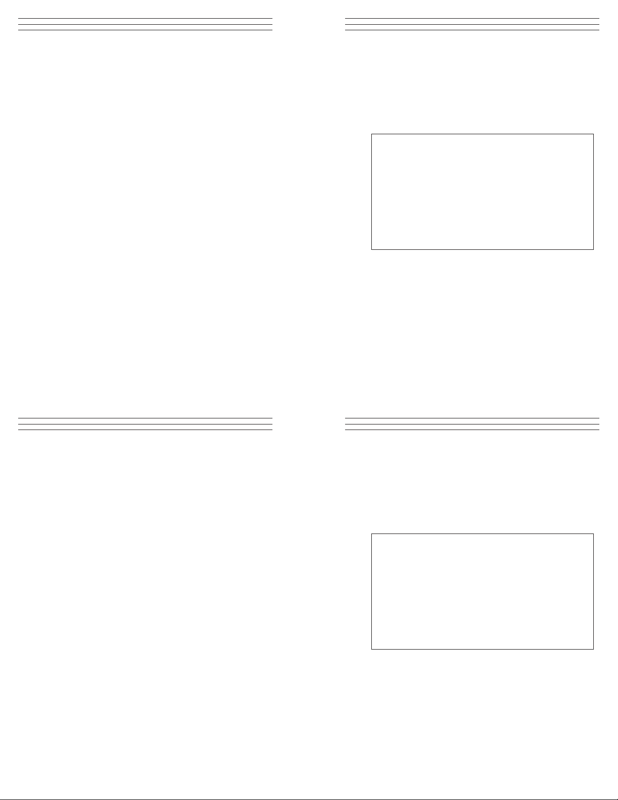
6.0. ONLINE STATISTICS DISPLAY
Every time a measurement is
take, a pair of statistical values
appear in the lower part of the
display, as shown at right.
For example:
n = 12 x = 2.8 mils
(n = number of measurements ; x = average)
Each time the STATS key is pressed, the number of measurements
and a different statistical value will appear, allowing the user to
easily scroll through statistics menu in the following sequence:
Press n = number of measurements; x = average
Press n = number of measurements s = standard deviation
Press n = number of measurements max = maximum reading
Press n = number of measurements min = minimum reading
You can pre-select a required pair of values by means of the STATS
key, for example n = 12 s = 0.1 mils, and have it displayed during
the entire measurement data recording process.
Note: After the stistical values are deleted, or before new
measurments are made, the display will show:
n = 0 x = mils
Important: If a series of measurements is meant to be statistically
evaluated, the old statistical values must be deleted
before starting a new series of measurements.
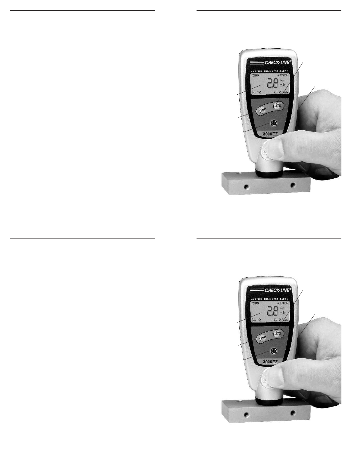
4.0 MEASURING USING FACTORY CALIBRATION
1. Press the ON/OFF switch to turn
the gauge on.
2. If the ZERO icon does not appear
in the upper left corner of the
display, the preset factory
calibration is activated.
If the ZERO icon does appear, it
indicates that a Zero Procedure
has been performed. See Clearing
a Zero Setting, Section 5.2 before
continuing.
3. Place the gauge on the test object and read the measurement. Lift
the gauge off of the test object by at least 1 inch (2.5 cm) before
taking another reading.
Note: Using the factory calibration, you can immediately carry out
measurements on flat and slightly curved surfaces. On strongly
curved or rough parts it is recommended that a ZERO procedure
be performed (see section 5.0).
DCFN-3000EZ Only: The DCFN-3000EZ automatically recognizes
whether the base material is a ferromagnetic steel or a non-ferrous
metal and will display the correct reading.
10
6.0. ONLINE STATISTICS DISPLAY
Every time a measurement is
take, a pair of statistical values
appear in the lower part of the
display, as shown at right.
For example:
n = 12 x = 2.8 mils
(n = number of measurements ; x = average)
Each time the STATS key is pressed, the number of measurements
and a different statistical value will appear, allowing the user to
easily scroll through statistics menu in the following sequence:
Press n = number of measurements; x = average
Press n = number of measurements s = standard deviation
Press n = number of measurements max = maximum reading
Press n = number of measurements min = minimum reading
You can pre-select a required pair of values by means of the STATS
key, for example n = 12 s = 0.1 mils, and have it displayed during
the entire measurement data recording process.
Note: After the stistical values are deleted, or before new
measurments are made, the display will show:
n = 0 x = mils
Important: If a series of measurements is meant to be statistically
evaluated, the old statistical values must be deleted
before starting a new series of measurements.
7
4.0 MEASURING USING FACTORY CALIBRATION
1. Press the ON/OFF switch to turn
the gauge on.
2. If the ZERO icon does not appear
in the upper left corner of the
display, the preset factory
calibration is activated.
If the ZERO icon does appear, it
indicates that a Zero Procedure
has been performed. See Clearing
a Zero Setting, Section 5.2 before
continuing.
3. Place the gauge on the test object and read the measurement. Lift
the gauge off of the test object by at least 1 inch (2.5 cm) before
taking another reading.
Note: Using the factory calibration, you can immediately carry out
measurements on flat and slightly curved surfaces. On strongly
curved or rough parts it is recommended that a ZERO procedure
be performed (see section 5.0).
DCFN-3000EZ Only: The DCFN-3000EZ automatically recognizes
whether the base material is a ferromagnetic steel or a non-ferrous
metal and will display the correct reading.
10
7
Page 8

5.0 PERFORMING A ZERO PROCEDURE
To obtain more accurate measurements on strongly curved or rough
parts, you should carry out the ZERO Procedure on a similar curved
reference piece without coating.
1. Press the ZERO key. ZERO flashes in the display.
2. Place the gauge on the bare surface several times. Lift the gauge
off of the surface by at least 1 inch (2.5 cm) between placements.
3. Press ZERO key again. The display shows ZERO
4. You can now carry out additional measurements.
Note: Zeroing is required if the convex radius of curvature
• is smaller than 1.2” (30mm) on steel parts,
• is smaller than 2.4” (60mm) on non-ferrous metal parts.
5.2 Clearing a zero setting and restoring factory
calibration
If the ZERO icon is shown on the display after switching
on (see top photo below), a custom calibration is activated.
To clear the custom setting:
1. Press the ZERO key twice. The ZERO icon disappears.
The factory calibration is active.You can now take
measurements using the factory calibration.
5.1 Checking accuracy
The foil standard included in the complete kit can be used
together with the suppled zero plates (Fe or Al) to check the
accuracy of the gauge. After zeroing, the measured thickness
of the foil will be displayed within the tolerance of the foil
plus the gauge accuracy.
8
5.0 PERFORMING A ZERO PROCEDURE
To obtain more accurate measurements on strongly curved or rough
parts, you should carry out the ZERO Procedure on a similar curved
reference piece without coating.
1. Press the ZERO key. ZERO flashes in the display.
2. Place the gauge on the bare surface several times. Lift the gauge
off of the surface by at least 1 inch (2.5 cm) between placements.
3. Press ZERO key again. The display shows ZERO
4. You can now carry out additional measurements.
Note: Zeroing is required if the convex radius of curvature
• is smaller than 1.2” (30mm) on steel parts,
• is smaller than 2.4” (60mm) on non-ferrous metal parts.
Custom calibration active
Custom calibration cleared
9
5.2 Clearing a zero setting and restoring factory
calibration
If the ZERO icon is shown on the display after switching
on (see top photo below), a custom calibration is activated.
To clear the custom setting:
1. Press the ZERO key twice. The ZERO icon disappears.
The factory calibration is active.You can now take
measurements using the factory calibration.
5.1 Checking accuracy
The foil standard included in the complete kit can be used
together with the suppled zero plates (Fe or Al) to check the
accuracy of the gauge. After zeroing, the measured thickness
of the foil will be displayed within the tolerance of the foil
plus the gauge accuracy.
8
Custom calibration active
Custom calibration cleared
9
Page 9

OI502
CHECK•LINE
BY ELECTROMATIC
Coating Thickness Gauges
DCF-3000EZ AND DCFN-3000EZ
®
CHECK•LINE
INSTRUMENTS
®
ELECTROMATIC
E Q U I P M E N T C O., I N C.
600 Oakland Ave., Cedarhurst, NY 11516–U.S.A.
TEL: 516-295-4300
•
FAX: 516-295-4399
www.checkline.com
Operating Instructions
OI502
CHECK•LINE
BY ELECTROMATIC
Coating Thickness Gauges
DCF-3000EZ AND DCFN-3000EZ
®
CHECK•LINE
INSTRUMENTS
®
ELECTROMATIC
E Q U I P M E N T C O., I N C.
600 Oakland Ave., Cedarhurst, NY 11516–U.S.A.
TEL: 516-295-4300
•
FAX: 516-295-4399
www.checkline.com
Operating Instructions
 Loading...