

Page 1

CHCNAV i50 GNSS
User Guide
Revision 1.0
June 01, 2018
Make your work more efficient
Page 2

Table of Content
Table of Content
Table of Content.................................................................................................... 2
Preface ................................................................................................................. 5
Copyright ................................................................................................................ 5
Safety Warnings ..................................................................................................... 5
FCC Interference Statement ................................................................................... 5
CE Interference Statement ..................................................................................... 6
1 Introduction ................................................................................................... 7
1.1 Safety Information ..................................................................................... 7
1.1.1 Warnings and Cautions ...................................................................... 7
1.1.2 Regulations and Safety ....................................................................... 7
1.1.3 Use and Care ...................................................................................... 8
1.2 Technical Support ....................................................................................... 8
1.3 Disclaimer ................................................................................................... 8
1.4 Your Comments .......................................................................................... 8
2 Getting Started with i50 .................................................................................. 9
2.1 About the Receiver .................................................................................... 9
2.2 Parts of the Receiver .................................................................................. 9
2.2.1 Front Panel ......................................................................................... 9
2.2.2 Lower Housing ................................................................................. 11
2.2.3 Receiver Ports .................................................................................. 12
2.3 Batteries and Power ................................................................................. 13
2.3.1 Internal Batteries ............................................................................. 13
2.3.2 External Power Supply ..................................................................... 14
2.4 Inserting Battery and SIM Card ................................................................ 15
2.5 Product Basic Supply Accessories ............................................................ 16
2.5.1 Base Kit Basic Supply ........................................................................ 16
2.5.2 Rover Kit Basic Supply ...................................................................... 18
2.6 Connecting to an Office Computer .......................................................... 19
2.7 Connecting to a Controller ....................................................................... 19
2.7.1 Connecting via Wi-Fi with LandStar 7 Software ............................... 19
2.7.2 Connecting via Bluetooth with LandStar 7 Software ....................... 21
2.8 Downloading Logged Data ....................................................................... 23
3 Base Station Setup and Operation .................................................................. 25
3.1 Base Station Setup Guidelines ................................................................. 25
3.2 Outputting Corrections Using Internal Radio Modem ............................. 26
3.2.1 Base Station Setup ........................................................................... 26
3.3 Outputting Corrections Using External Radio .......................................... 27
CHCNAV i50 GNSS USER GUIDE | 2018-11 P a g e | 2
Page 3

Table of Content
4 Rover Station Setup And Operation ................................................................ 29
4.1 Rover Station Setup Guidelines................................................................ 29
4.2 Rover Station Setup .................................................................................. 30
5 Configuring Through a Web Browser .............................................................. 31
5.1 Status Menu ............................................................................................. 32
5.1.1 Position Submenu ............................................................................ 33
5.1.2 Activity Submenu ............................................................................. 33
5.1.3 Google Map Submenu ..................................................................... 34
5.2 Satellites Menu ........................................................................................ 34
5.2.1 Tracking Table Submenu .................................................................. 35
5.2.2 Tracking Info. Table Submenu .......................................................... 35
5.2.3 Tracking Skyplot Submenu ............................................................... 36
5.2.4 Satellite Activation Submenu ........................................................... 36
5.2.5 Tracking Enable Submenu ................................................................ 37
5.3 Receiver Configuration Menu .................................................................. 38
5.3.1 Description ....................................................................................... 38
5.3.2 Antenna Configuration Submenu .................................................... 38
5.3.3 Reference Station Settings Submenu ............................................... 39
5.3.4 Receiver Reset Submenu ................................................................. 42
5.3.5 Languages Submenu ........................................................................ 42
5.3.6 User Management Submenu ........................................................... 42
5.3.7 USB Function Switch Submenu ........................................................ 43
5.3.8 HCPPP Settings Submenu................................................................. 43
5.4 Data Recording Menu .............................................................................. 43
5.4.1 Log Settings Submenu ...................................................................... 43
5.4.2 FTP Push Settings Submenu ............................................................. 45
5.4.3 FTP Push Log Submenu .................................................................... 46
5.4.4 Data Download Submenu ................................................................ 46
5.5 IO Settings Menu ...................................................................................... 48
5.5.1 IO Settings Submenu ........................................................................ 48
5.6 Network Setting Menu ............................................................................. 54
5.6.1 Description Submenu ....................................................................... 55
5.6.2 Mobile Network Setting Submenu................................................... 55
5.6.3 Email Alarm Submenu ...................................................................... 56
5.6.4 HTTP Submenu ................................................................................. 57
5.6.5 HTTPS Submenu ............................................................................... 57
5.6.6 FTP Service Submenu ....................................................................... 58
5.7 Module Setting Menu .............................................................................. 58
5.7.1 Description Submenu ....................................................................... 59
5.7.2 WiFi Submenu .................................................................................. 59
5.7.3 Bluetooth Settings Submenu ........................................................... 59
CHCNAV i50 GNSS USER GUIDE | 2018-11 P a g e | 3
Page 4

Table of Content
5.7.4 Radio Settings Submenu .................................................................. 60
5.8 Firmware Menu ........................................................................................ 61
5.8.1 Firmware Info Submenu ................................................................... 61
5.8.2 Hardware Version Submenu ............................................................ 61
5.8.3 Config File Submenu ........................................................................ 62
5.8.4 System Log Download Submenu ...................................................... 62
5.8.5 User Log Submenu ........................................................................... 63
5.8.6 Firmware Update Submenu ............................................................. 63
5.8.7 GNSS Board Upgrade Submenu ....................................................... 64
5.8.8 Radio Upgrade Submenu ................................................................. 64
5.8.9 Upgrade Online Submenu ................................................................ 64
5.8.10 GNSS Registration Submenu ........................................................ 64
5.9 Cloud Service Setting Menu ..................................................................... 65
5.9.1 Cloud Service Setting Submenu ....................................................... 65
A Communication Ports Definition .................................................................... 67
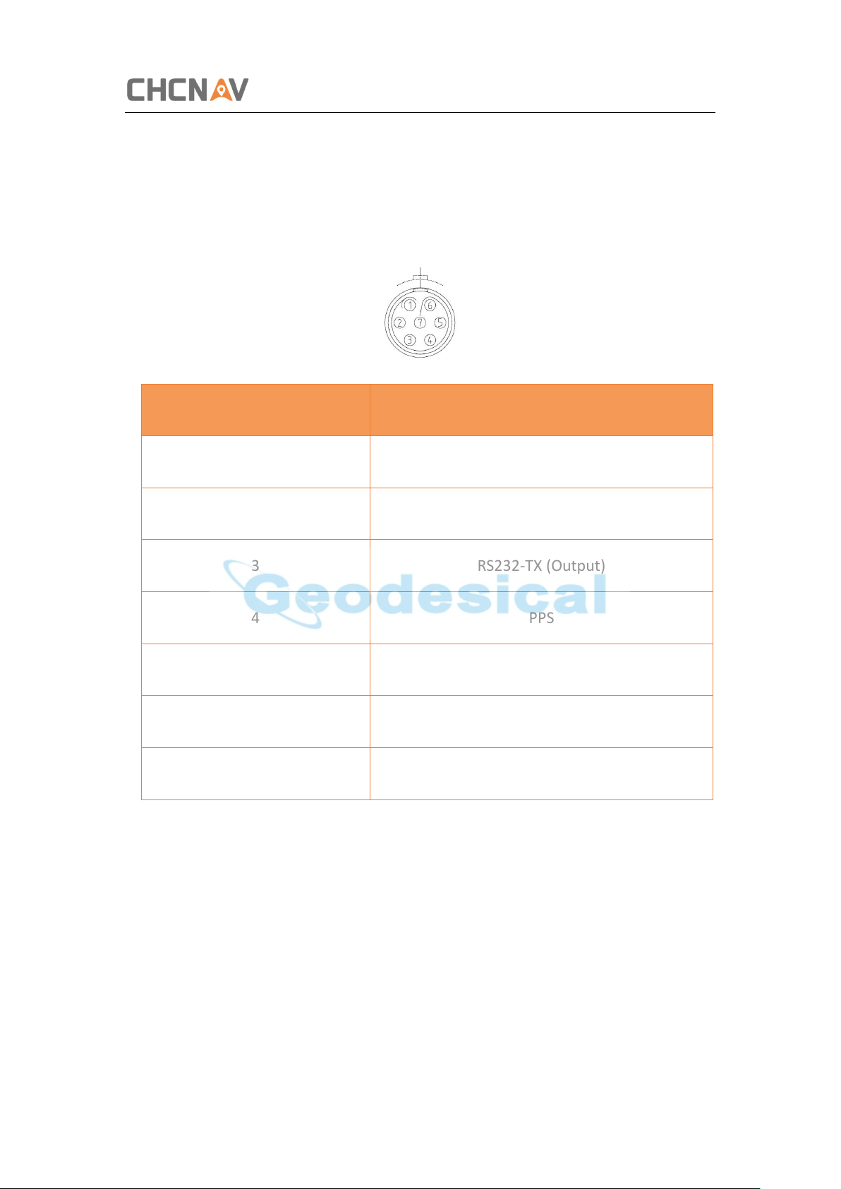
AI CHC i50 Receiver IO Port (7-pin Lemo Port) Definition ................................ 67
CHCNAV i50 GNSS USER GUIDE | 2018-11 P a g e | 4
Page 5

Preface
Preface
Copyright
Copyright 2016-2017
CHC | Shanghai Huace Navigation Technology Ltd. All rights reserved. The CHC are
trademark of Shanghai Huace Navigation Technology Limited. All other trademarks are
the property of their respective owners.
Trademarks
All product and brand names mentioned in this publication are trademarks of their
respective holders.
Safety Warnings
The Global Positioning System (GPS) is operated by the U.S. Government, which is
solely responsible for the accuracy and maintenance of the GPS network. Accuracy can
also be affected by poor satellite geometry and obstructions, like buildings and heavy
canopy.
FCC Interference Statement
This equipment has been designed to comply with the limits for a Class B digital device,
pursuant to part 15 of the FCC Rules in the Portable Mode. These limits are designed
to provide reasonable protection against harmful interference in a residential
installation.
Operation is subject to the following two conditions: (1) this device may not cause
harmful interference and (2) this device must accept any interference received,
including interference that may cause undesired operation.
CHCNAV i50 GNSS USER GUIDE | 2018-11 P a g e | 5
Page 6

Preface
CE Interference Statement
Declaration of Conformity: Hereby, Shanghai Huace Navigation Technology Ltd.
declares that this i50 is in compliance with the essential requirements and other
relevant provisions of Directive 2014/53/EU. A copy of the Declaration of conformity
can be found at Shanghai Huace Navigation Technology Ltd.
CHCNAV i50 GNSS USER GUIDE | 2018-11 P a g e | 6
Page 7
Introduction
1 Introduction
The i50 GNSS Receiver User Guide describes how to set up and use the CHC® i50 GNSS
receiver.
In this manual, “the receiver” refers to the i50 GNSS receiver unless otherwise stated.
Even if you have used other Global Navigation Satellite Systems (GNSS) products
before, CHC recommends that you spend some time reading this manual to learn
about the special features of this product. If you are not familiar with GNSS, go to
www.chcnav.com for an interactive look at CHC and GNSS.
1.1 Safety Information
1.1.1 Warnings and Cautions
An absence of specific alerts does not mean that there are no safety risks involved.
A Warning or Caution information is intended to minimize the risk of personal injury
and/or damage to the equipment.
WARNING - A Warning alerts you to a potential misused or wrong setting of the
equipment.
CAUTION - A Caution alerts you to a possible risk of serious injury to your person
and/or damage to the equipment.
1.1.2 Regulations and Safety
The receivers contain a built-in wireless modem for signal communication through
Bluetooth® wireless technology or through external communication datalink.
Regulations regarding the use of the wireless modem vary greatly from country to
country. In some countries, the unit can be used without obtaining an end-user license.
However, in some countries, the administrative permissions are required. For license
information, consult your local dealer. Bluetooth® operates in license-free bands.
Before operating a i50 GNSS receiver, determine if authorization or a license to operate
the unit is required in your country. It is the responsibility of the end-user to obtain an
operator's permit or license for the receiver for the location or country of use.
CHCNAV i50 GNSS USER GUIDE | 2018-11 P a g e | 7
Page 8

Introduction
1.1.3 Use and Care
This receiver is designed to withstand the rough environment that typically occurs in
the field. However, the receiver is high-precision electronic equipment and should be
treated with reasonable care.
CAUTION - Operating or storing the receiver outside the specified temperature
range will cause irreversible damage.
1.2 Technical Support
If you have a problem and cannot find the information you need in this manual or CHC
website (www.chcnav.com), contact your local CHC dealer from which you purchased
the receiver(s).
If you need to contact CHC technical support, please contact us by email
([email protected]) or Skype (chc_support).
1.3 Disclaimer
Before using the receiver, please make sure that you have read and understood this
User Guide, as well as the safety information. CHC holds no responsibility for the wrong
operation by users and for the losses incurred by the wrong understanding about this
User Guide. However, CHC reserves the rights to update and optimize the contents in
this guide regularly. Please contact your local CHC dealer for new information.
1.4 Your Comments
Your feedback about this user guide will help us to improve it in future revision. Please
email your comments to [email protected].
CHCNAV i50 GNSS USER GUIDE | 2018-11 P a g e | 8
Page 9

Getting Started with i50
Front panel
2 Getting Started with i50
2.1 About the Receiver
The i50 GNSS receiver incorporates a GNSS engine, GNSS antenna, internal radio (410
MHz – 470 MHz), 4G cellular modem, Bluetooth, Wi-Fi, and dual-battery in a
ruggedized and miniature unit that is easy for you to set up an all-in-one RTK rover or
mobile base station. Bluetooth and Wi-Fi technology provide cable-free
communication between the receiver and controller.
The receiver can be used as the part of a RTK GNSS system with CHC LandStar 7
software. And you can download the GNSS data that recorded in the internal memory
of receiver to a computer.
To configure the receiver for performing a wide variety of functions, you can use the
web interface by connecting the receiver with PC or smartphone through Wi-Fi.
2.2 Parts of the Receiver
The operating controls are all located on the front panel. Battery compartment and
SIM card slot are on the backside. Serial ports and connectors are located on the
bottom of the unit.
2.2.1 Front Panel
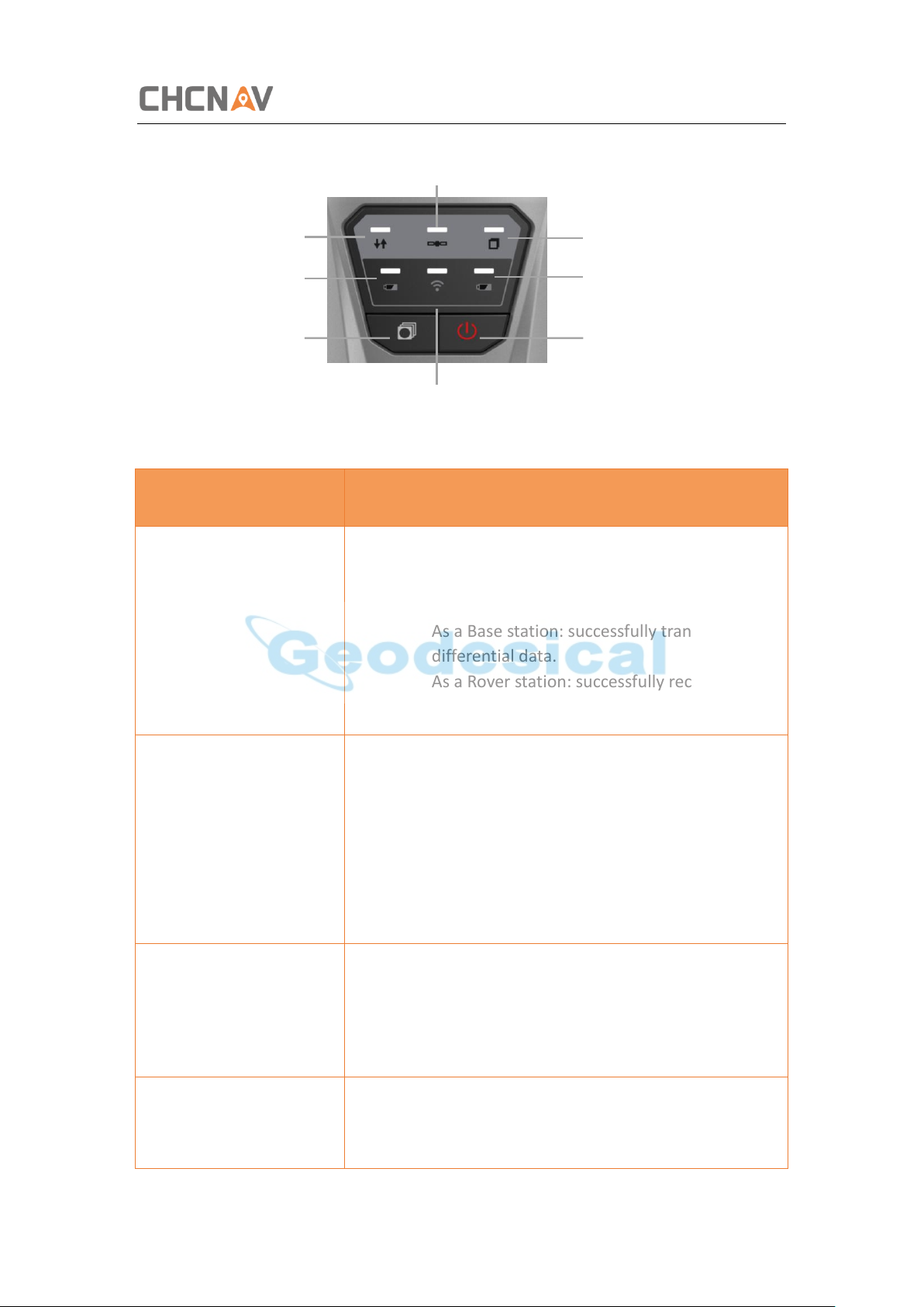
The following figure shows a front view of the receiver.
The front panel contains six indicator LEDs and two buttons.
CHCNAV i50 GNSS USER GUIDE | 2018-11 P a g e | 9
Page 10
Getting Started with i50
Name
Description
Correction LED (Green)
• Indicates whether the receiver is
transmitting/receiving differential data.
• The green LED flashes once per second when
As a Base station: successfully transmitting
differential data.
As a Rover station: successfully receiving
differential data from Base station.
Satellite LED (Blue)
• Shows the number of satellites that the
receiver has tracked.
• When the receiver is searching satellites, the
blue LED flashes once every 5 seconds.
• When the receiver has tracked N satellites,
the blue LED will flash N times every 5
seconds.
Static LED (Yellow)
• Indicates whether the receiver is recording
static data.
• When the receiver is recording static data,
the yellow LED flashes as setting frequency.
Battery A LED/ Battery B
LED (Red)
• Indicates whether the receiver is out of
power.
• When the receiver is out of power, the red
Satellite LED
Correction LED
Static LED
Fn button
Power button
Battery A LED
Battery B LED
Wi-Fi LED
CHCNAV i50 GNSS USER GUIDE | 2018-11 P a g e | 10
Page 11
Getting Started with i50
LED flashes.
Wi-Fi LED (Red)
• Indicates whether the receiver Wi-Fi is
opened.
• When the receiver Wi-Fi is opened, the red
LED turns on.
Fn button
• Move to next line of the menus or options.
• Move to next character of the value that you
want to make change.
• Cancel the change you make on a function.
Power button
• Works as a Power button:
• Press and hold this button for 3 seconds to
turn on or turn off the receiver.
• Works as a Reset button:
• Hold Fn button, and press this button for 5
times continuously to reset the mainboard.
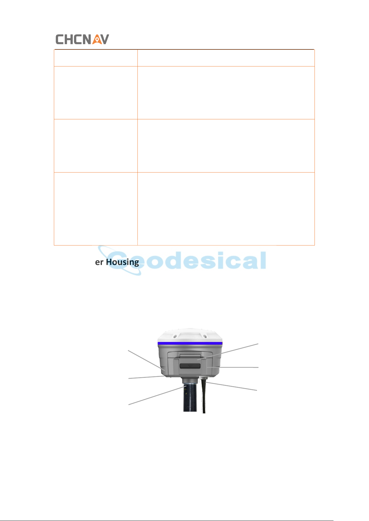
TNC radio
antenna
connector
SIM card
slot
IO serial communication
and power in port
USB communication
and power in port
Battery
5/8-11 threaded
2.2.2 Lower Housing
The lower housing contains one SIM card slot, two battery compartments, one TNC
radio antenna connector, two communication and power ports, one 5/8-11 threaded
insert, and two nameplates.
CHCNAV i50 GNSS USER GUIDE | 2018-11 P a g e | 11
Page 12
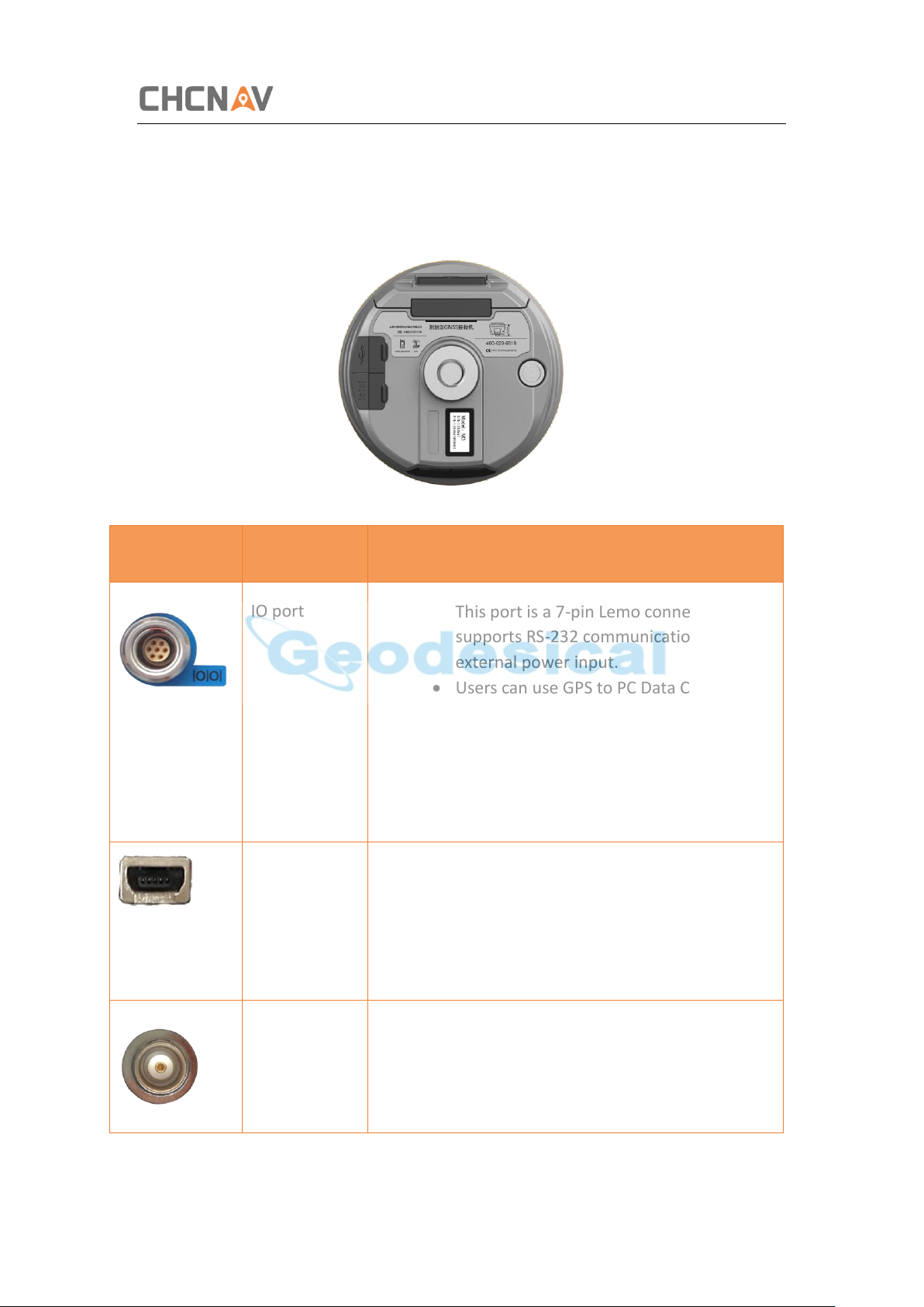
2.2.3 Receiver Ports
Port
Name
Description
IO port
• This port is a 7-pin Lemo connector that
supports RS-232 communications and
external power input.
• Users can use GPS to PC Data Cable
supplied with the system to realize RS-232
communications between the receiver
and computer or controller. Also, users
can use a 7-pin cable to transmit
differential data to an external radio.
USB port
• This port is a mini-USB connector that
supports USB communications.
• Users can use USB Cable supplied with
the system to download the logged data
to a computer.
Radio
antenna
connector
• Connect a radio antenna to internal radio
of the receiver. And this connector is not
used if you are using an external radio.
Getting Started with i50
CHCNAV i50 GNSS USER GUIDE | 2018-11 P a g e | 12
Page 13

Getting Started with i50
2.3 Batteries and Power
2.3.1 Internal Batteries
The receiver has two rechargeable Lithium-ion batteries, which can be removed for
charging.
2.3.1.1 Charging the Battery
The rechargeable Lithium-ion battery is supplied partially charged. Charge the battery
completely before using it for the first time. To charge the battery, first remove the
battery from the receiver, and then place it in the battery charger, which is connected
to AC power.
WARNING - Charge and use the rechargeable Lithium-ion battery only in strict
accordance with the instructions. Charging or using the battery in unauthorized
equipment can cause an explosion or fire, and can result in personal injury and/or
equipment damage.
To prevent injury or damage:
•Do not charge or use the battery if it appears to be damaged or leaking.
•Charge the Lithium-ion battery only in a CHC product that is specified to charge it. Be
sure to follow all instructions that are provided with the battery charger.
•Discontinue charging a battery that gives off extreme heat or a burning odor.
•Use the battery only in CHC equipment that is specified to use it.
•Use the battery only for its intended use and according to the instructions in the
product documentation.
2.3.1.2 Battery Safe
WARNING - Do not damage the rechargeable Lithium-ion battery. A damaged
battery can cause an explosion or fire, and can result in personal injury and/or property
damage.
To prevent injury or damage:
•Do not use or charge the battery if it appears to be damaged. Signs of damage include,
but are not limited to, discoloration, warping, and leaking battery fluid.
CHCNAV i50 GNSS USER GUIDE | 2018-11 P a g e | 13
Page 14

Getting Started with i50
•Do not expose the battery to fire, high temperature, or direct sunlight.
•Do not immerse the battery in water.
•Do not use or store the battery inside a vehicle under hot weather condition.
•Do not drop or puncture the battery.
•Do not open the battery or short-circuit its contacts.
WARNING - Avoid contact with the rechargeable Lithium-ion battery if it appears
to be leaking. Battery fluid is corrosive, and contact with it can result in personal injury
and/or property damage.
To prevent injury or damage:
•If the battery leaks, avoid with the battery fluid.
•If battery fluid gets into your eyes, immediately rinses your eyes with clean water and
seek medical attention. Please do not rub your eyes!
•If battery fluid gets onto your skin or clothing, immediately use clean water to wash
off the battery fluid.
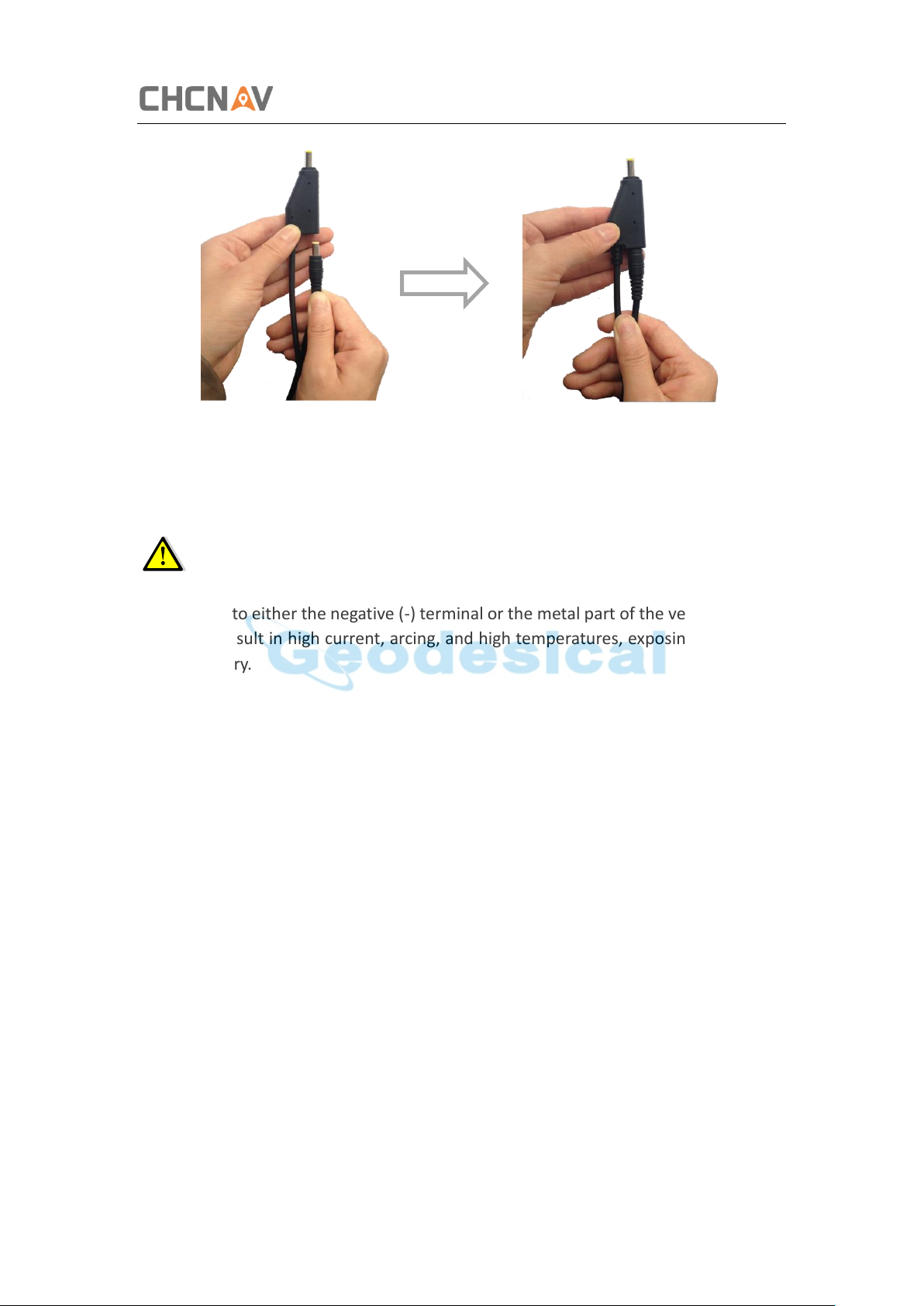
2.3.2 External Power Supply
Two methods are available for providing the external power to the receiver by the GPS
to PC Data Cable+ Power Adapter, or GPS to PC Data Cable + external power cable
(option purchase) + vehicle battery.
In the office:
The Power Adapter is connecting with AC power of 100-240V, the output port of the
Power Adapter connects with the Power Port of the GPS to PC Data Cable.
CHCNAV i50 GNSS USER GUIDE | 2018-11 P a g e | 14
Page 15
Getting Started with i50
In the field:
The external power cable is connecting with a vehicle battery, the output port of the
external power cable connects with the Power Port of the GPS to PC Data Cable.
WARNING - Use caution when connecting external power cable's clip leads to a
vehicle battery. Do not allow any metal object to connect (short) the battery's positive
(+) terminal to either the negative (-) terminal or the metal part of the vehicle battery.
This could result in high current, arcing, and high temperatures, exposing the user to
possible injury.
2.4 Inserting Battery and SIM Card
Push down the spring-loaded button on the battery cover to open the cover.
Make electrode sheets of battery turn toward the receiver, align the socket of the
battery and the lug of the battery compartment, and then insert the battery into the
battery compartment until it is locked by the battery bail.
To remove the battery, slide the battery bail to the left or right.
CHCNAV i50 GNSS USER GUIDE | 2018-11 P a g e | 15
Page 16

Getting Started with i50
Item
Picture
i50 GNSS Receiver
UHF Bar Antenna (410-470 MHz)
Push down
Battery bail
Battery cover
Insert the SIM card with the contacts facing upward, as indicated by the SIM card icon
next to the SIM card slot.
To eject the SIM card, slightly push it in to trigger the spring-loaded release mechanism.
Tip – The SIM card is provided by your cellular network service provider.
2.5 Product Basic Supply Accessories
2.5.1 Base Kit Basic Supply
CHCNAV i50 GNSS USER GUIDE | 2018-11 P a g e | 16
Page 17

Getting Started with i50
USB Cable
GPS to PC Data Cable
Lithium Battery
H.I. Tape
Extension pole
Tribrach with optical plummet
Auxiliary H.I. Tool
Tribrach adaptor
Transport Hard Case
CHCNAV i50 GNSS USER GUIDE | 2018-11 P a g e | 17
Page 18
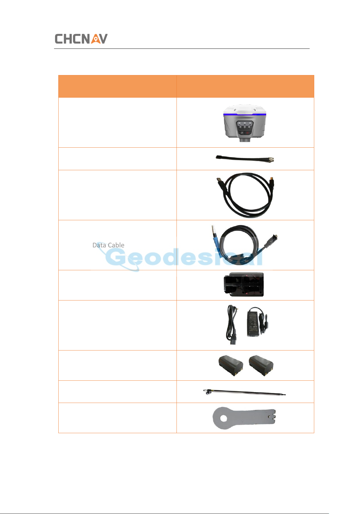
2.5.2 Rover Kit Basic Supply
Item
Picture
i50 GNSS Receiver
UHF Bar Antenna (410-470 MHz)
USB Cable
GPS to PC Data Cable
Battery Charger
Power Adapter with Cord
Lithium Battery
2M Range Pole w/bag
Auxiliary H.I. Tool
Getting Started with i50
CHCNAV i50 GNSS USER GUIDE | 2018-11 P a g e | 18
Page 19
Getting Started with i50
Transport Hard Case
GPS to PC Data Cable
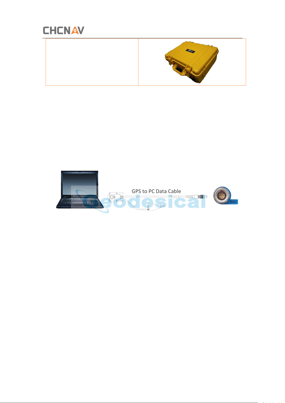
2.6 Connecting to an Office Computer
The receiver can be connected to an office computer for serial data transfer or settings
via a GPS to PC Data Cable. Before you connect to the office computer, ensure that the
receiver is powered on by internal battery or external power.
The following figure shows how to connect to the computer for serial data transfer or
settings:
2.7 Connecting to a Controller
2.7.1 Connecting via Wi-Fi with LandStar 7 Software
Turn on the controller → run LandStar 7 → go to Config main menu → tap Connect.
In the Connect screen, select CHC for the Manufacture field, i50 for Device Type field,
WIFI for Connection Type field.
CHCNAV i50 GNSS USER GUIDE | 2018-11 P a g e | 19
Page 20
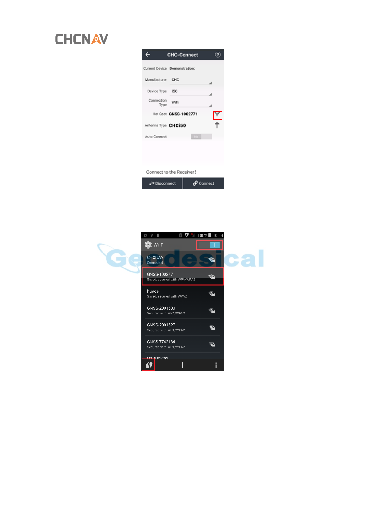
Getting Started with i50
Tap the Wireless Lan icon on the right side to select the hot-spot → Switch on the WiFi
module by the top switch → tap refresh button to search the hot spot around → select
the target device in the list.
Tap Connect to link to the hot spot. If the first-time connection to this hot spot, user
may type in the password.
CHCNAV i50 GNSS USER GUIDE | 2018-11 P a g e | 20
Page 21
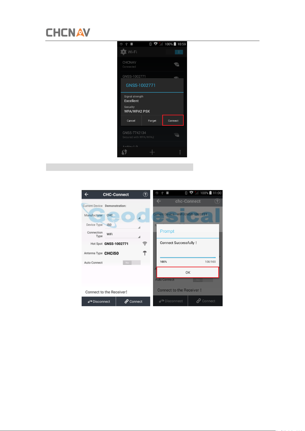
Tip – The Wi-Fi key of the receiver is 12345678 by default.
Tap the Connect button to build the connection.
Getting Started with i50
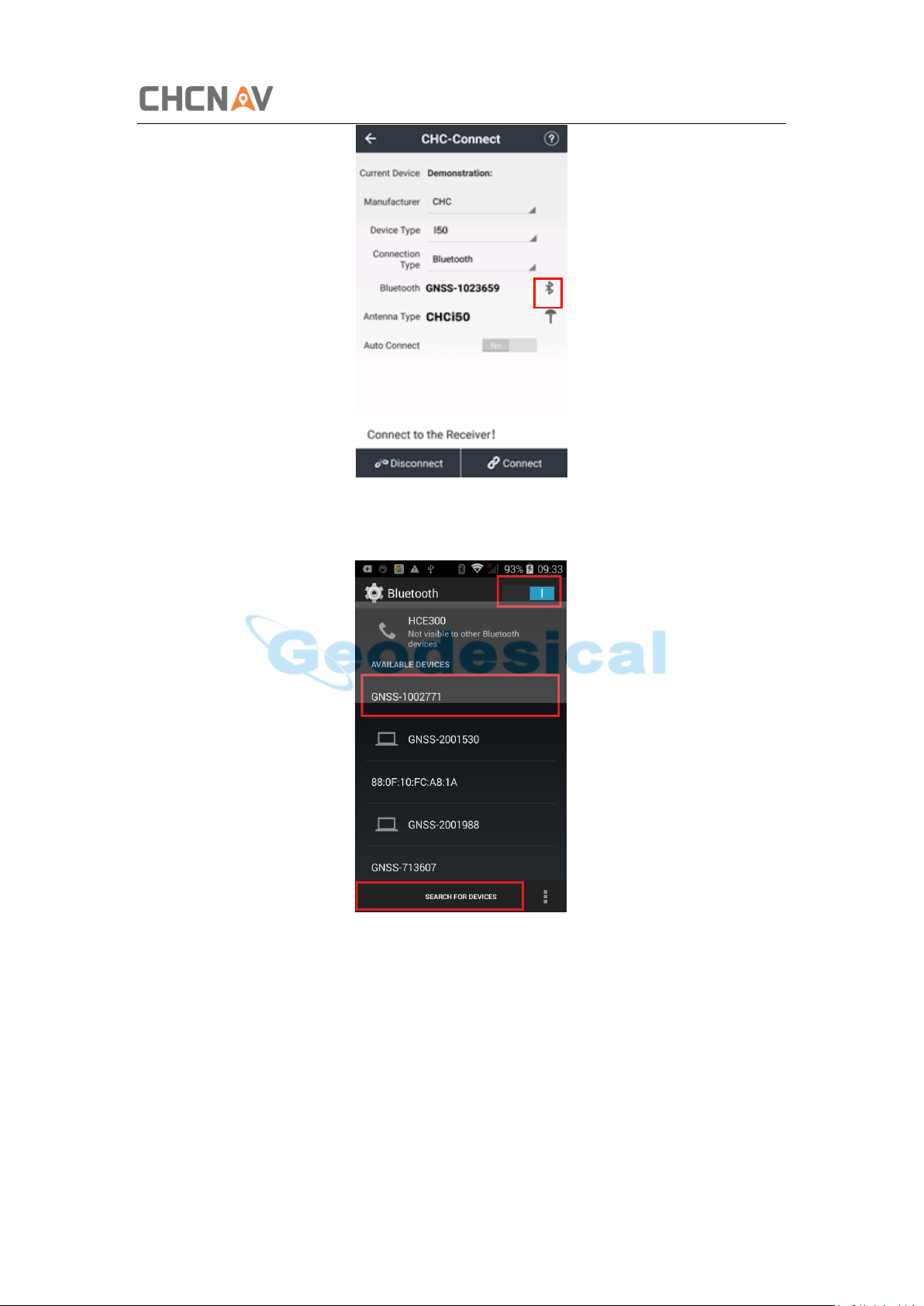
2.7.2 Connecting via Bluetooth with LandStar 7 Software
Turn on the controller → run LandStar 7 → go to Config main menu → tap Connect.
In the Connect screen, select CHC for the Manufacture field, i50 for Device Type field,
Bluetooth for Connection Type field.
CHCNAV i50 GNSS USER GUIDE | 2018-11 P a g e | 21
Page 22
Getting Started with i50
Tap the Bluetooth Manager and turn on the Bluetooth function to search bluetooth
device around → select the target device in the list.
Tap Pair to connect the bluetooth device → selected the target device in the bluetooth
manager list
CHCNAV i50 GNSS USER GUIDE | 2018-11 P a g e | 22
Page 23
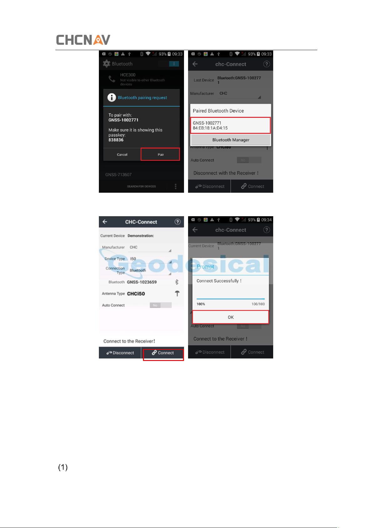
Tap the Connect button to build the connection.
Getting Started with i50
2.8 Downloading Logged Data
Data logging involves the collection of GNSS measurement data over a period at a
static point or points, and subsequent post-processing of the information to accurately
compute baseline information. Data logging using receivers requires access to suitable
GNSS post-processing software such as the CHC Geomatics Office (CGO) Software.
The procedures of downloading logged data in the receiver are as follows:
Switch on the receiver and connect it with a computer by USB Cable. After the
CHCNAV i50 GNSS USER GUIDE | 2018-11 P a g e | 23
Page 24
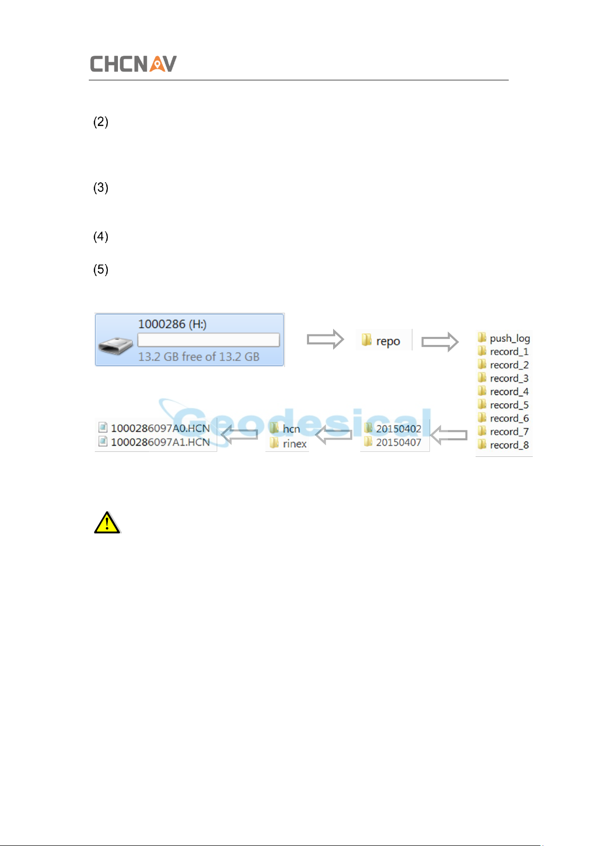
Getting Started with i50
successful connection, a removable disk named as the Serial Number (SN) of the
receiver will appear on the computer.
Double click the removable disk and you will see the folder named as “repo”.
Double click this folder, you will see 9 folders. The “push_log” folder is used to
save the log files, and the other 8 folders represent different logging session and
are used for store static data.
Double click the folder that you have configured to store the static data, you will
see the folder(s) created by the i50 system automatically and named by the date
which is decide by GPS time when you start to log data.
Select the destination folder and double click it, and then two folders named as
different data format (hcn and rinex) will be displayed.
Select the data format that you has configured to save the static data, you will find
the static raw data.
Tip – For hcn files, the name of the file is represented as XXXXXXDDDNN, where
XXXXXX is the SN of the receiver, DDD is day of year, and NN is the recording session.
WARNING – The static data will be saved in the first logging session, the
“record_1” folder, by default. Old files will be deleted if the storage space is full. If you
configure not to auto delete old files when the memory is low, the receiver will stop
data logging.
CHCNAV i50 GNSS USER GUIDE | 2018-11 P a g e | 24
Page 25
Base Station Setup and Operation
3 Base Station Setup and Operation
Real-Time Kinematic (RTK) operation provides centimeter-level precision by
eliminating errors that are present in the GNSS system. For all RTK operations, you
require both a rover receiver and a source of corrections from a base station or
network of base stations.
A base station consists of a receiver that is placed at a known point. The receiver tracks
the same satellites that are being tracked by the rover receiver simultaneously. Errors
in the GNSS system are monitored at the base station, and a series of position
corrections are computed. The messages are sent through a radio link to the rover
receiver, where they are used to correct the real time positions of the rover.
This chapter provides the information to help you identify good setup locations,
outlines basic precautions that you need to take to protect the equipment, and
describes the conventional process to set up the base station and the configuring
procedure that required for transmitting correction data.
3.1 Base Station Setup Guidelines
For good performance, the following base station setup guidelines are recommended:
• Place the GNSS receiver in a location on the worksite where equal range in all
directions provides full coverage of the site.
• Place the GNSS antenna in a location that has a clear line of sight to the sky in all
directions. Do not place the antenna near vertical obstructions such as buildings,
deep cuttings, site vehicles, towers, or tree canopy.
• The GNSS antenna must have a dear line of sight to the sky at all times during
operation.
• Place the GNSS and radio antennas as high as practical. This minimizes multipath
from the surrounding area, and enables the radio to broadcast to the maximum
distance.
• Choose the most appropriate radio antenna for the size of the worksite. The
higher the gain on the antenna, the longer the range.
• Make sure that the GNSS receiver does not lose power. To operate continuously
for more than a few hours without loss of power at the base station, provide
external power. When you use an external power supply, the integrated battery
provides a backup power supply, enabling you to maintain continuous operation
through a mains power failure.
• Do not locate a GNSS receiver, GNSS antenna, or radio antenna within 400
CHCNAV i50 GNSS USER GUIDE | 2018-11 P a g e | 25
Page 26
Base Station Setup and Operation
meters (about 1,300 feet) of transmitters, such as a power radar or cellular
communications tower.
• Do not set up the base station close to the sources of electromagnetic
interference, include alternators and generators, electric motors, equipment
with DC-to-AC converters, etc.
• Do not operate the receiver outside the specified operating temperature range -
40°C to +60°C (-40°F to +140°F).
• Take reasonable care to keep the GNSS receiver equipment dry, which could
prolong their life and reduce the effects of corrosion on ports and connectors.
3.2 Outputting Corrections Using Internal Radio Modem
3.2.1 Base Station Setup
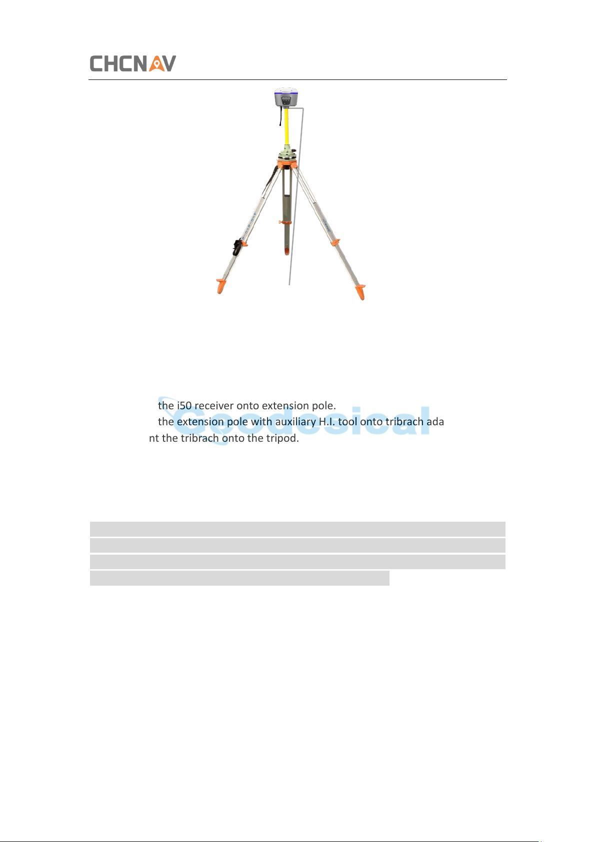
1. Connect the radio antenna onto i50 receiver. Screw the receiver onto extension
pole.
2. Screw the extension pole with auxiliary H.I. tool onto tribrach adaptor.
3. Mount the tribrach onto the tripod.
4. Insert the tribrach adaptor into the tribrach.
5. Level and plumb the receiver over the known (control) point.
6. Measure the height of the base station GNSS antenna by measuring the slant
height from the known (control) point to the end of auxiliary H.I. tool.
Note –After entered the vertical height from the known (control) point to the bottom
of receiver that you calculated by adding the height of the extension pole to the height
from the known (control) point to the auxiliary H.I. tool, LandStar 7 will calculate the
height to the Antenna Phase Center (APC) automatically.
7. If required, connect the receiver to an external 12 V power supply.
CHCNAV i50 GNSS USER GUIDE | 2018-11 P a g e | 26
Page 27
Base Station Setup and Operation
Slant height
3.3 Outputting Corrections Using External Radio
For base receiver part:
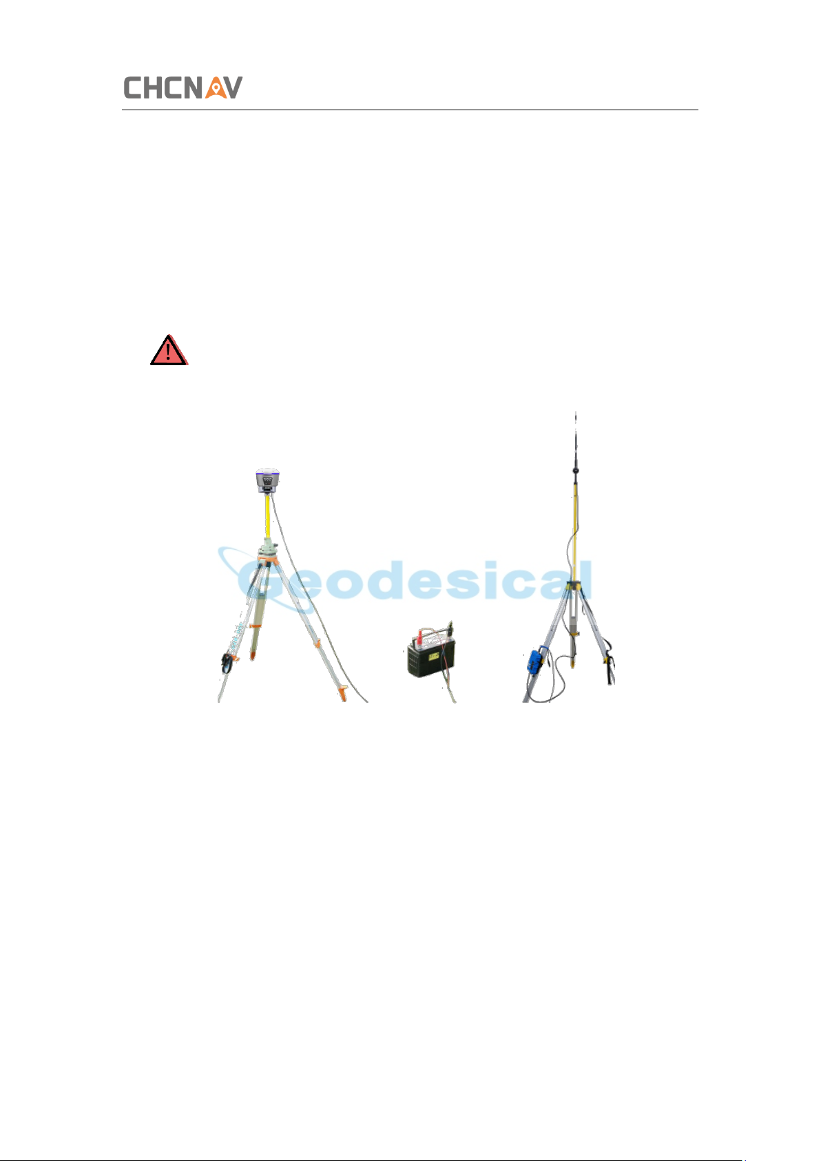
1. Screw the i50 receiver onto extension pole.
2. Screw the extension pole with auxiliary H.I. tool onto tribrach adaptor.
3. Mount the tribrach onto the tripod.
4. Insert the tribrach adaptor into the tribrach.
5. Level and plumb the receiver over the known (control) point.
6. Measure the height of the base station GNSS antenna by measuring the slant
height from the known (control) point to the auxiliary H.I. tool.
Note – After entered the vertical height from the known (control) point to the bottom
of receiver that you calculated by adding the height of the extension pole to the height
from the known (control) point to the end of auxiliary H.I. tool, LandStar 7 will calculate
the height to the Antenna Phase Center (APC) automatically.
7. If required, connect the receiver to an external 12 V power supply.
For external radio part (take the CHC DL6 Datalink for example):
8. Connect the Datalink Antenna to the 3 meter Cable for Datalink Antenna.
9. Connect 3 meter Cable for Datalink Antenna to Datalink Antenna Mounting
Pole.
10. Screw the Datalink Antenna Mounting Pole onto the tribrach adapter.
11. Mount the tribrach onto the tripod.
12. Insert the tribrach adaptor into the tribrach.
CHCNAV i50 GNSS USER GUIDE | 2018-11 P a g e | 27
Page 28
Base Station Setup and Operation
13. Set up the Datalink Antenna nearby the base receiver.
14. Fix the DL6 Datalink onto the tripod.
15. Place the car battery at an appropriate location.
For connection between the receiver part and external radio part:
16. Connect Datalink Antenna to the Datalink Antenna Slot of DL6 Datalink via 3
meter Cable for Datalink Antenna.
17. Connect the base receiver with DL6 Datalink via GPS to Datalink Cable.
18. Connect the car battery with DL6 Datalink via Datalink External Power Cable.
CAUTION – The Datalink Antenna must be connected to the Datalink before
the Datalink is powered on; otherwise, the Datalink can be damaged.
CHCNAV i50 GNSS USER GUIDE | 2018-11 P a g e | 28
Page 29
Rover Station Setup And Operation
4 Rover Station Setup And Operation
Real-Time Kinematic (RTK) operation provides centimeter-level precision by
eliminating errors that are present in the GNSS system. For all RTK operations, you
require both a rover receiver and a source of corrections from a base station or
network of base stations.
The second part of the RTK GNSS system is the rover receiver. The rover receiver is
moved between the points that require measurement or stakeout. The rover receiver
is connected to a base station or to a source of RTK corrections such as a CORS
(Continuous Operational Reference System) or the CHC APIS service. The connection
is provided by:
• an integrated radio
• an integrated cellular modem
• a cellular modem in the controller
This chapter provides the information to help you identify good setup locations,
describes the conventional process to set up the rover station and the configuring
procedure that required for receiving correction data.
4.1 Rover Station Setup Guidelines
For good rover operation, observe the following setup guidelines:
• Place the GNSS antenna in a location that has a clear line of sight to the sky in
all directions. Do not place the antenna near vertical obstructions such as
buildings, deep cuttings, site vehicles, towers, or tree canopy. GNSS rovers and
the base station receive the same satellite signals from the same satellites. The
system needs five common satellites to provide RTK positioning.
WARNING – Take care not to touch overhead power lines with the CHC i50
GNSS receiver or the range pole when moving the equipment into position.
Touching overhead power lines may cause electrocution, leading to serious injury.
• GNSS satellites are constantly moving. Because you cannot measure at a
specific location now does not mean that you will not be able to measure there
later, when satellite coverage at the location improves.
• To get a fixed position solution with centimeter precision, initialize the RTK
rover receiver. For initialization to take place, the receiver must track at least
five satellites that the base station is also tracking. In a dual-satellite
CHCNAV i50 GNSS USER GUIDE | 2018-11 P a g e | 29
Page 30
Rover Station Setup And Operation
constellation operation, for example, GPS and GLONASS, the receiver must
track at least six satellites.
• To continue to survey at centimeter precisions, the rover must continuously
track at least four satellites that the base station is also tracking. The radio link
between the base and rover receivers must also be maintained.
• Loss of the satellite signals will result in a loss of centimeter position precision.
4.2 Rover Station Setup
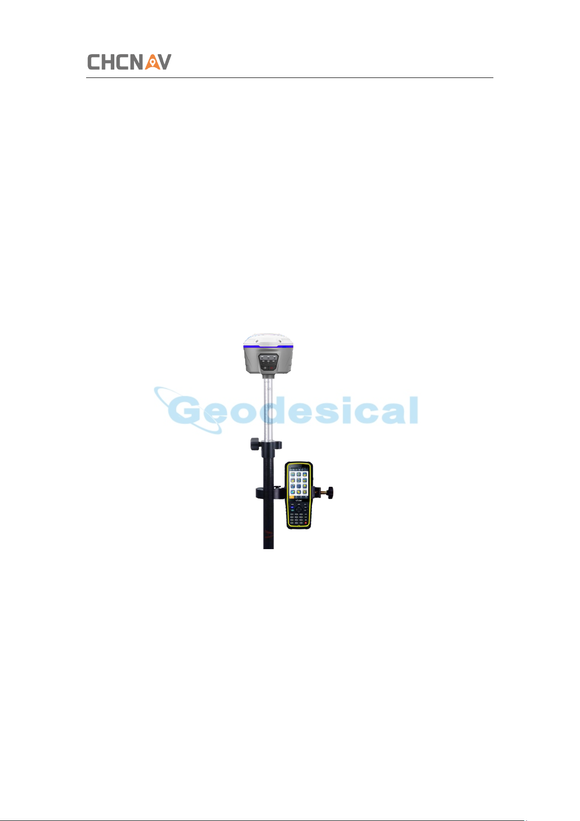
1. If required, connect the radio antenna onto i50 receiver.
2. Screw the receiver on top of the range pole.
3. Fix the controller bracket on the range pole.
4. Fit the controller in the controller bracket.
5. Level and plumb the receiver over the target measuring point.
CHCNAV i50 GNSS USER GUIDE | 2018-11 P a g e | 30
Page 31
Configuring Through a Web Browser
5 Configuring Through a Web Browser
Supported browsers:
• Google Chrome
R
• Microsoft Internet Explorer
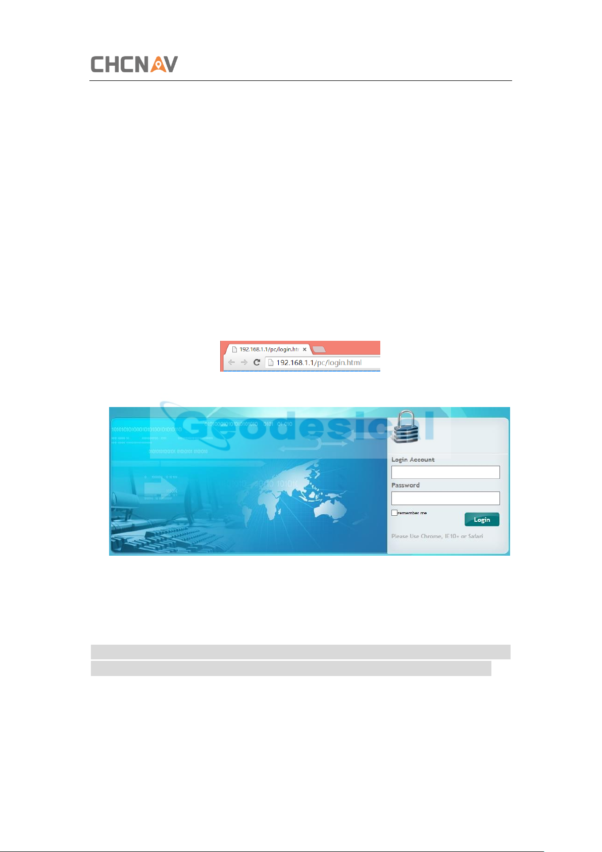
To connect to the receiver through a web browser:
1. Turn on the Wi-Fi of the receiver.
2. Search the wireless network named as GNSS-XXXXXXX (the SN of your receiver) on
your computer, and then establish the connection.
3. After the successful connection between your computer and the receiver, enter
the IP address of the receiver into the address bar of the web browser on your
computer:
○
version 10, or higher
4. The web browser prompts you to enter a login account and password:
The default login account for the receiver is:
➢ Login Account: admin
➢ Password: password
Note – Tick remember me option, and then the browser will remember the Login
Account and Password you entered for the next time you enter this login screen.
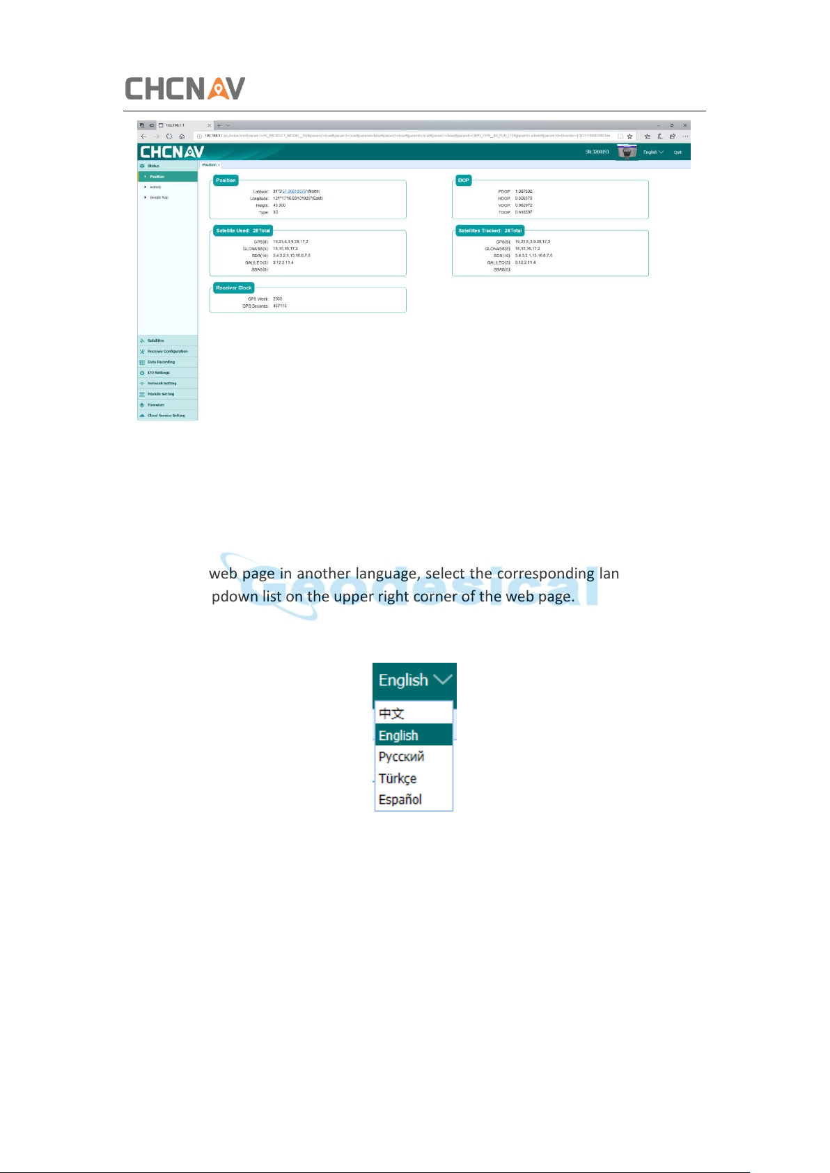
5. Once you are logged in, the web page appears as follows:
CHCNAV i50 GNSS USER GUIDE | 2018-11 P a g e | 31
Page 32
Configuring Through a Web Browser
This web page shows the configuration menus on the left of the browser window, and
the setting on the right. Each configuration menu contains the related submenus to
configure the receiver and monitor receiver performance.
This chapter describes each configuration menu.
To view the web page in another language, select the corresponding language name
from the dropdown list on the upper right corner of the web page.
Currently, three languages are available:
5.1 Status Menu
This menu provides a quick link to review the receiver's position information, satellites
tracked, runtime, current data log status, current outputs, available memory, and more.
CHCNAV i50 GNSS USER GUIDE | 2018-11 P a g e | 32
Page 33
Configuring Through a Web Browser
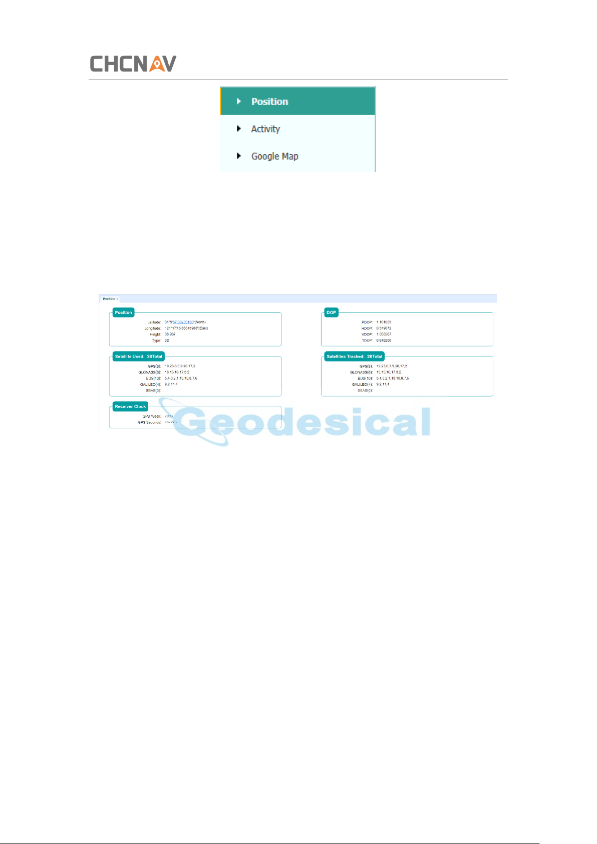
5.1.1 Position Submenu
This page shows the relevant position information about the receiver's position
solution which including the position, DOP values, satellites used and tracked, and the
receiver clock information.
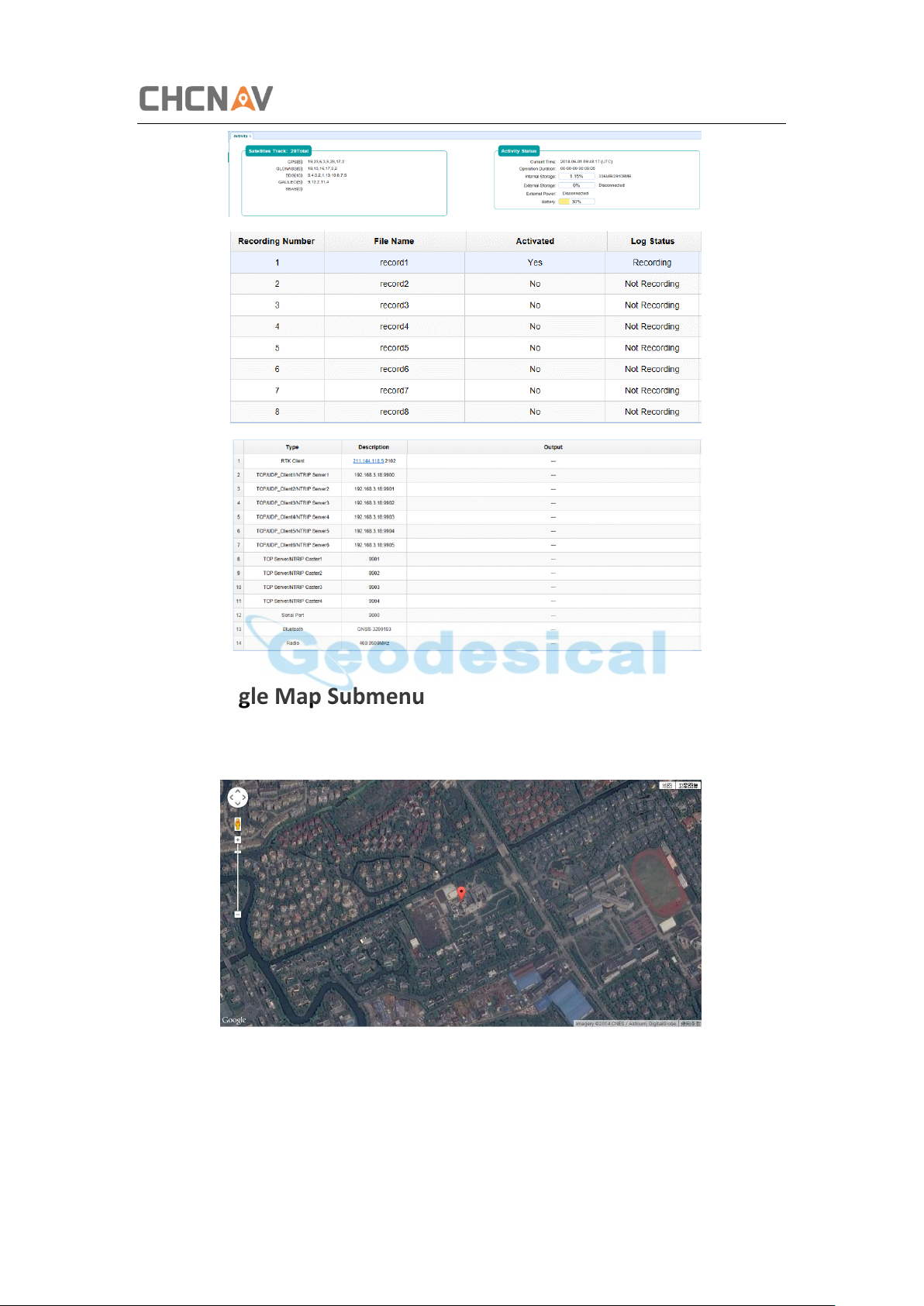
5.1.2 Activity Submenu
Lists several important items to help you understand how the receiver is being used
and its current operating condition. Items include the identities of currently tracked
satellites, internal and external storage usage rate, how long the receiver has been
operational, state of the internal battery, power source state, files being logged, and
data streams being output. With this information, it is easy to tell exactly what
functions the receiver is performing:
CHCNAV i50 GNSS USER GUIDE | 2018-11 P a g e | 33
Page 34
Configuring Through a Web Browser
5.1.3 Google Map Submenu
Tap this submenu to show the location of the receiver on Google map.
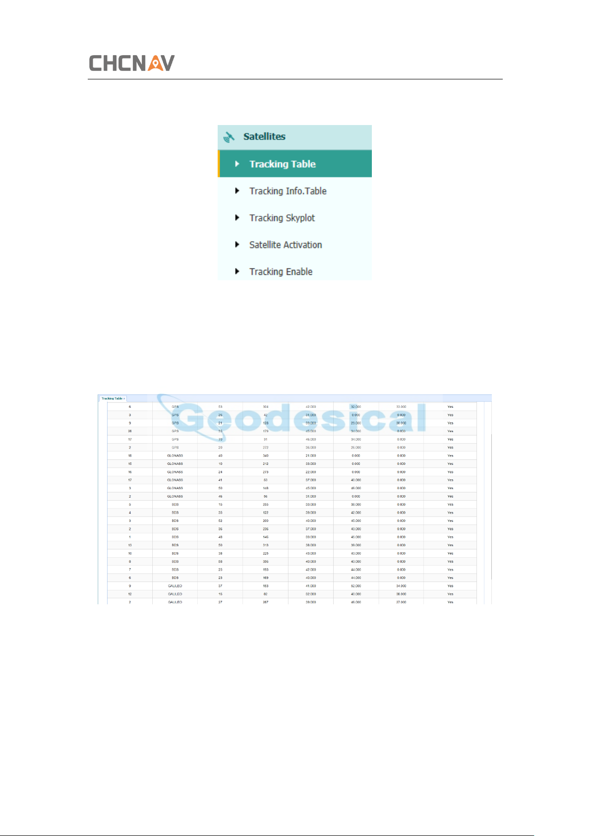
5.2 Satellites Menu
Use the Satellites menu to view satellite tracking details and enable/disable GPS,
CHCNAV i50 GNSS USER GUIDE | 2018-11 P a g e | 34
Page 35
Configuring Through a Web Browser
SBAS, GLONASS, BDS and Galileo constellations. These menus include tabular and
graphical displays to provide all required information on satellite tracking status.
5.2.1 Tracking Table Submenu
Provides the status of satellites tracked in general, such as the satellite ID, satellite type,
attitude angle, azimuth angle, L1 SNR, L2 SNR, L5 SNR and enable/disable status of
each one.
5.2.2 Tracking Info. Table Submenu
The following figure is an example of satellite track diagram page. Users can determine
the satellite types and the corresponding SNR of L-band carriers to be displayed in any
combination.
CHCNAV i50 GNSS USER GUIDE | 2018-11 P a g e | 35
Page 36
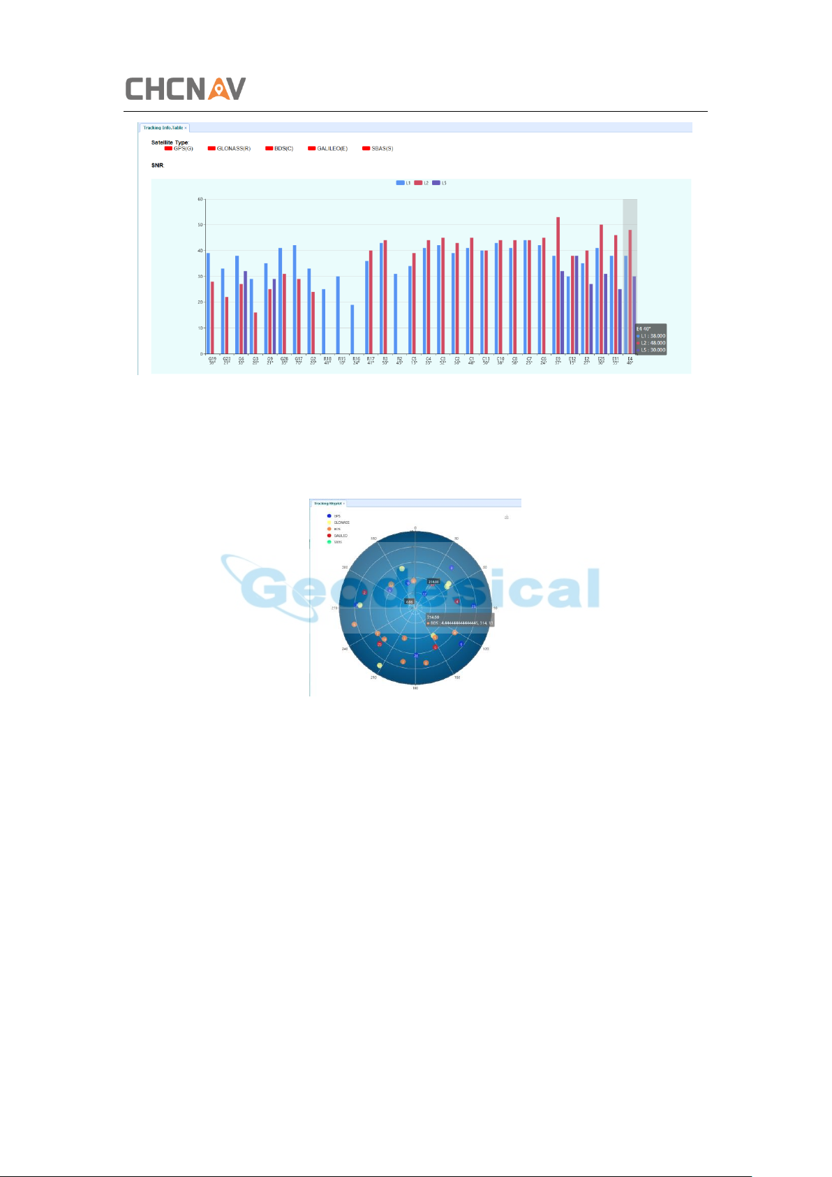
5.2.3 Tracking Skyplot Submenu
The following figure is an example of Skyplot page.
Configuring Through a Web Browser
5.2.4 Satellite Activation Submenu
Use this menu to enable or disable satellites.
CHCNAV i50 GNSS USER GUIDE | 2018-11 P a g e | 36
Page 37
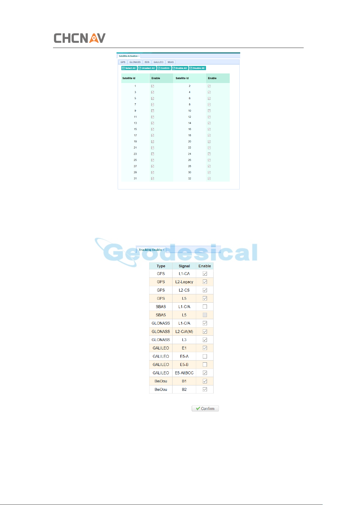
5.2.5 Tracking Enable Submenu
Configuring Through a Web Browser
Use this menu to enable or disable tracking signals.
CHCNAV i50 GNSS USER GUIDE | 2018-11 P a g e | 37
Page 38
Configuring Through a Web Browser
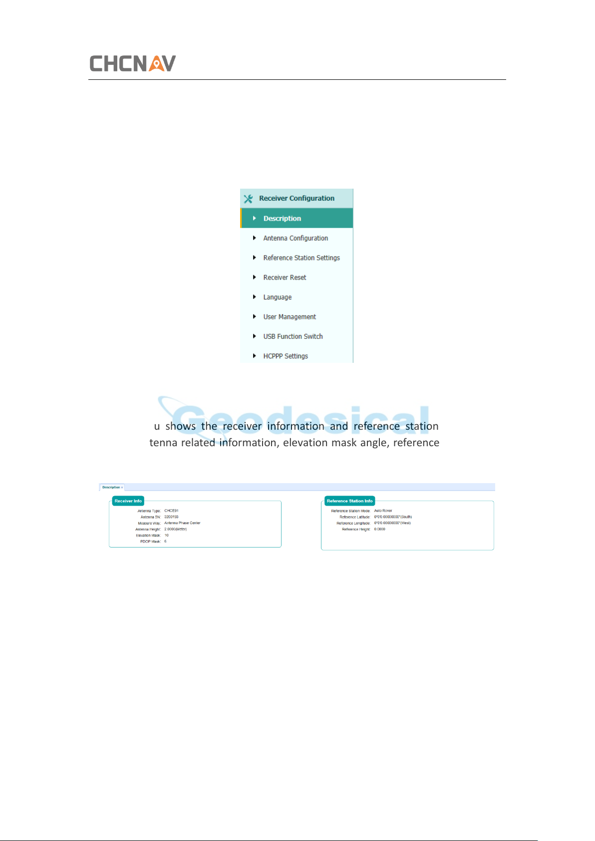
5.3 Receiver Configuration Menu
Use this menu to configure settings such as the antenna type and height, elevation
mask and PDOP setting, the reference station coordinates, receiver resetting and web
interface language:
5.3.1 Description
This submenu shows the receiver information and reference station information,
including antenna related information, elevation mask angle, reference station work
mode and position, etc.
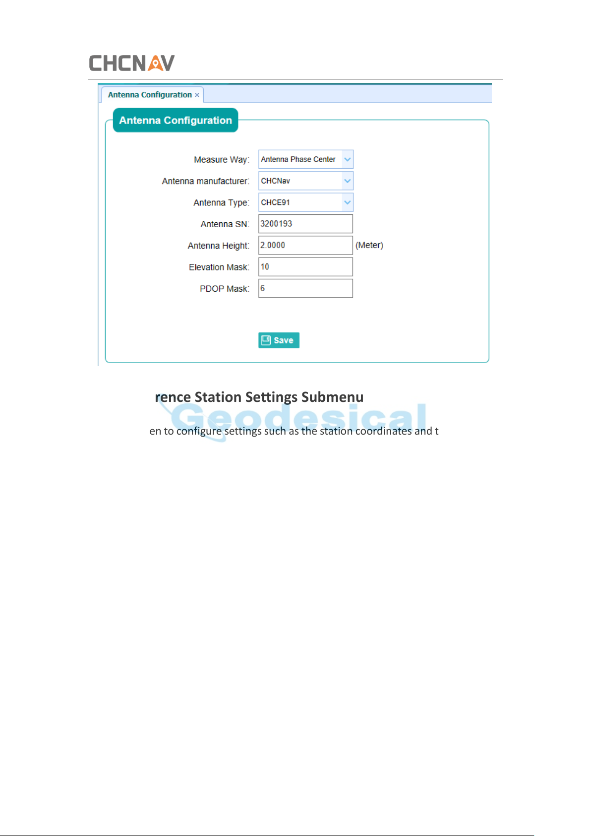
5.3.2 Antenna Configuration Submenu
Use this screen to configure all of the items relating to the GNSS antenna. You must
enter the correct values for all antenna-related fields, as the choices you make
significantly affect the accuracy for logged data and broadcast correction data:
CHCNAV i50 GNSS USER GUIDE | 2018-11 P a g e | 38
Page 39
Configuring Through a Web Browser
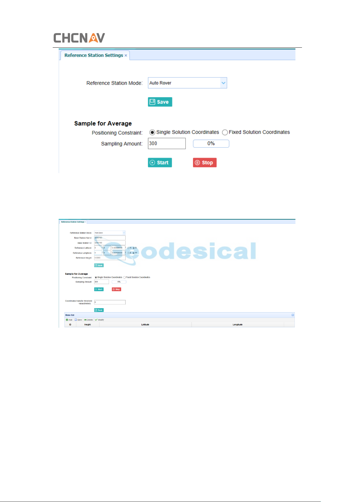
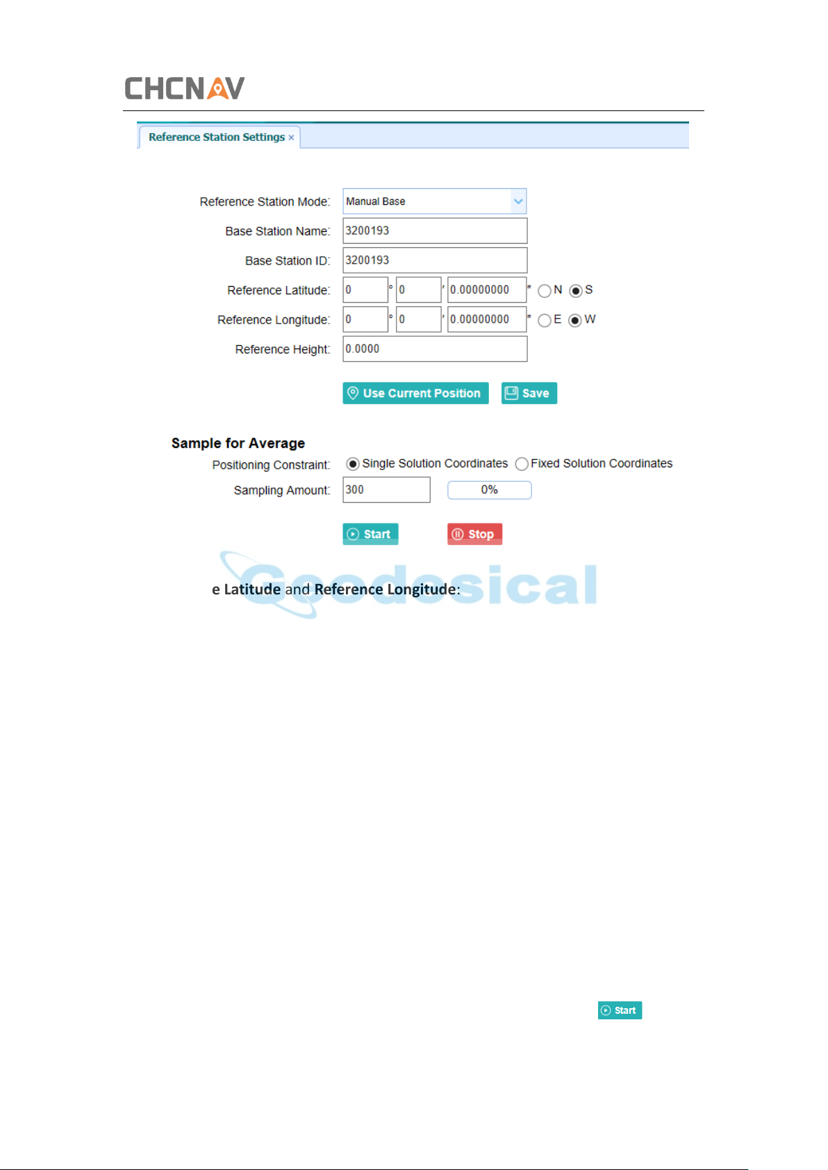
5.3.3 Reference Station Settings Submenu
Use this screen to configure settings such as the station coordinates and the broadcast
station identifiers. You must enter accurate information in these fields, as this data
significantly affects the accuracy of logged data files and broadcast correction data:
For Reference Station Mode:
There are three modes available:
a) Auto Rover: The receiver will serve as a rover after this mode is enabled, and
then receive correction data through the working mode set last time.
CHCNAV i50 GNSS USER GUIDE | 2018-11 P a g e | 39
Page 40
Configuring Through a Web Browser
b) Auto Base: The receiver will serve as a base after this mode is enabled, and
then broadcast correction data based on coordinate inputted by user, or
obtained through autonomous positioning automatically.
c) Manual Base: The receiver will serve neither as a base or a rover after this
mode is enabled. Users need to configure the receiver manually.
CHCNAV i50 GNSS USER GUIDE | 2018-11 P a g e | 40
Page 41
Configuring Through a Web Browser
For Reference Latitude and Reference Longitude:
There are mainly three methods to enter the reference coordinates and shown as
follows:
a) Acquire Current Position: Click this button to acquire current position obtained
through autonomous positioning automatically.
b) Manual Input: Manually input the coordinate of a control point.
c) From CORS: After the receiver logging in CORS, the software can record the
coordinate of current position based on fix solution.
For Sample for Average:
Users can determine the positioning limit and sampling amount. The positioning limit
falls into two types:
a) Single Solution Coordinates: Collect the coordinates of receiver obtained
through autonomous positioning.
b) Fixed Solution Coordinates: Only collect coordinates of receiver with a fixed
solution.
After the configuration of positioning limit and sampling amount, click to carry
out sampling and averaging → the progress bar will show the progress → the result
CHCNAV i50 GNSS USER GUIDE | 2018-11 P a g e | 41
Page 42
Configuring Through a Web Browser
will be served as the coordinate of current positon.
If users need to save the changes, please tap button.
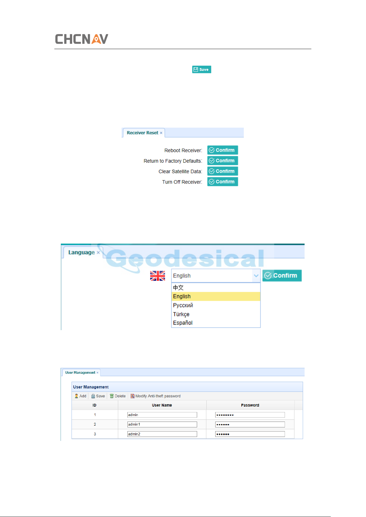
5.3.4 Receiver Reset Submenu
Use this screen to completely or partially reset the receiver:
5.3.5 Languages Submenu
Use this screen to select the web interface language:
5.3.6 User Management Submenu
CHCNAV i50 GNSS USER GUIDE | 2018-11 P a g e | 42
Page 43
Configuring Through a Web Browser
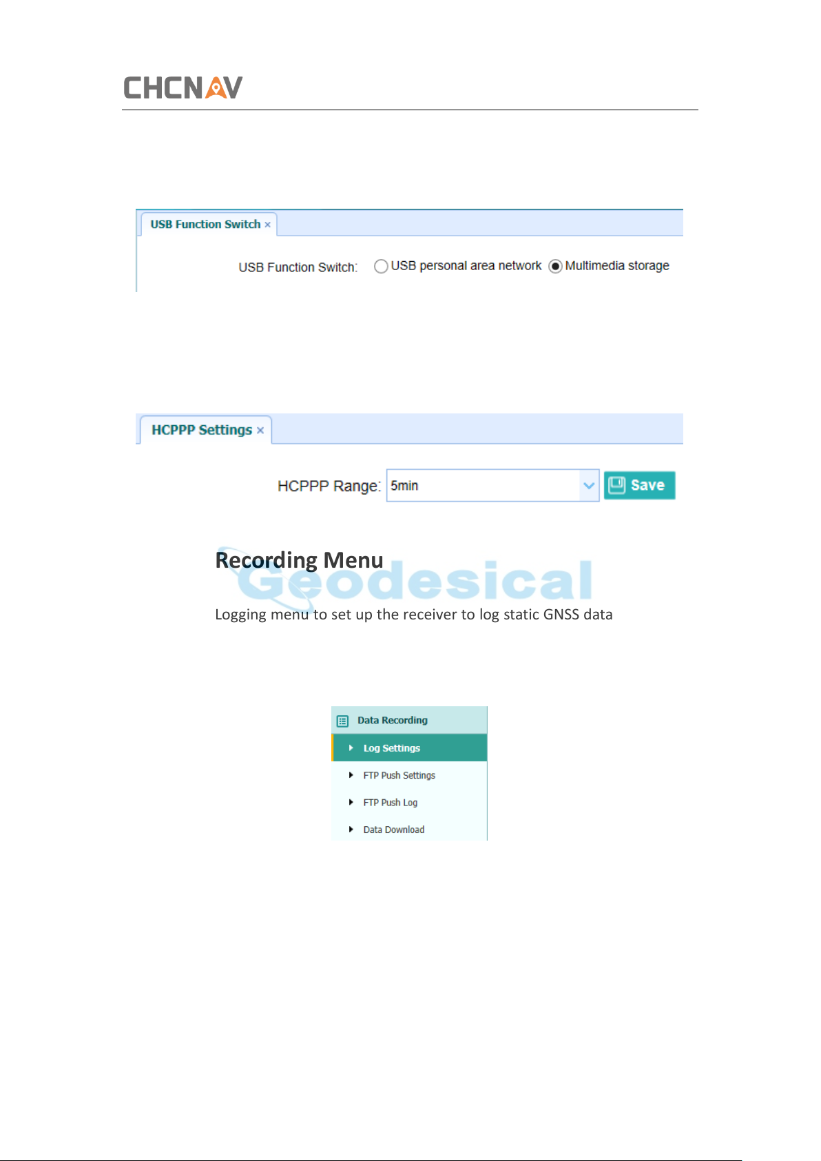
5.3.7 USB Function Switch Submenu
Use this menu to switch between USB personal area network and Multimedia storage.
5.3.8 HCPPP Settings Submenu
Use this menu to select HCPPP Range.
5.4 Data Recording Menu
Use the Data Logging menu to set up the receiver to log static GNSS data and to view
the logging settings. You can configure settings such as observable rate, recording rate,
continuous logging limit, and whether to auto delete old files if memory is low. This
menu also provides the controls for the FTP push feature:
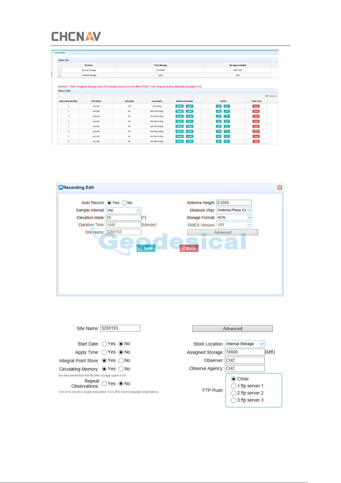
5.4.1 Log Settings Submenu
Here shows the data logging status, including internal and external storage usage and
data logging status of each session. Also, users can configure the data logging settings
for each session, including recording name, store location, storage limit, store formats,
start time, etc.
CHCNAV i50 GNSS USER GUIDE | 2018-11 P a g e | 43
Page 44
Configuring Through a Web Browser
To edit the settings of each session, click the Modify button to the right of the required
session, and then the Recording Edit screen appears:
Click advanced to see more settings.
In this screen, you can configure all the data logging parameters, and determine
CHCNAV i50 GNSS USER GUIDE | 2018-11 P a g e | 44
Page 45
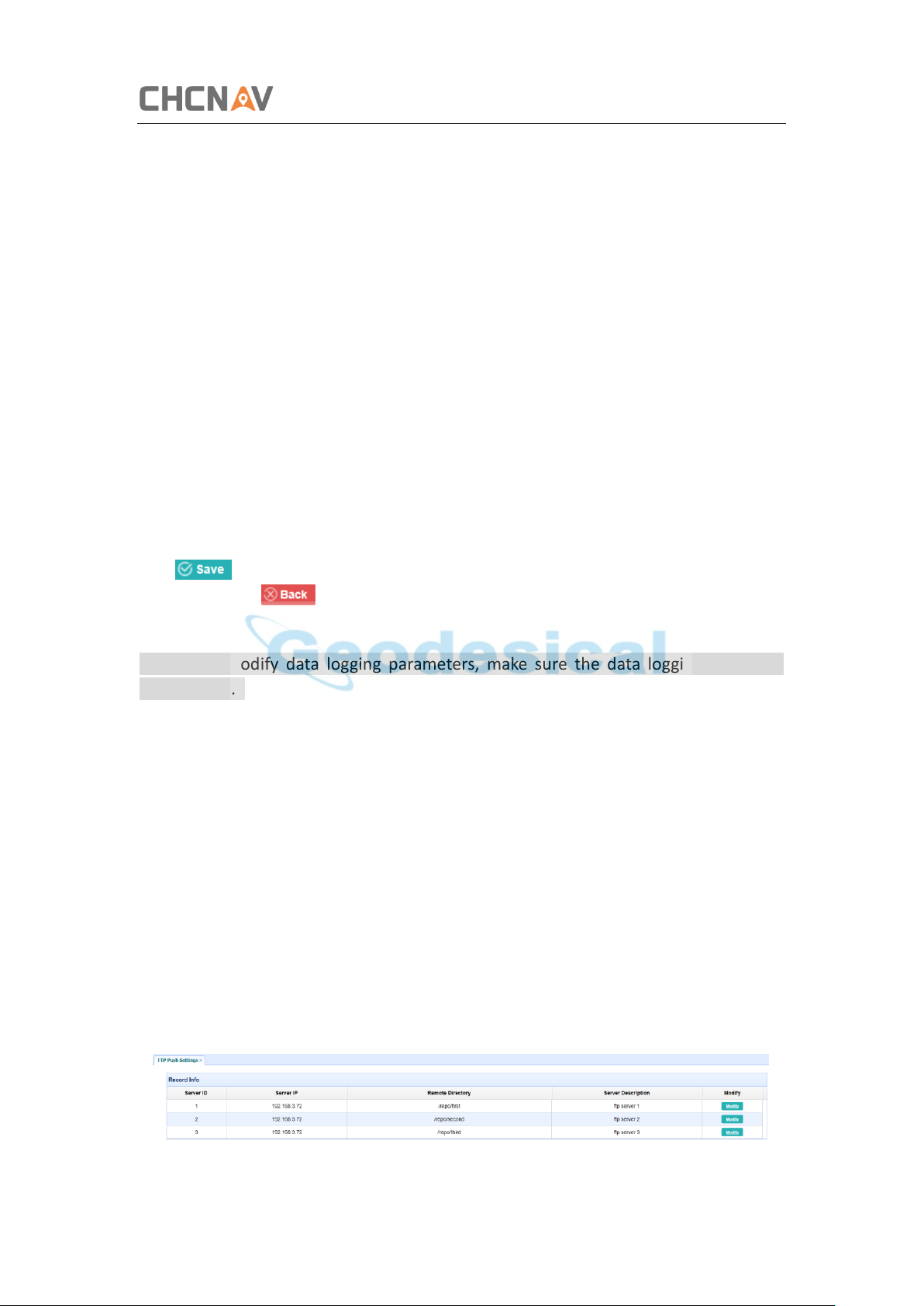
Configuring Through a Web Browser
whether the recording files will be affected by the FTP Push. The parameters are
mainly as follows:
➢ File Name: The name of this logging session.
➢ Sample Interval: Select the observable rate from the dropdown list.
➢ Store Location: Determine whether to store at internal storage or external
storage.
➢ Enable Start Time: Set the start time of data logging in UTC. Select Or not
option below to determine whether to start data logging from the start time
defined, or immediately after this session is switched on.
➢ Duration Time: Set the duration of data logging.
➢ Assigned Storage: Set the storage space of this session.
➢ Circulating Memory: Select Yes or No option to determine whether to auto
delete old files if the storage space is full.
➢ Data Format: Set the data format of the logged data.
➢ FTP Push: Decide whether to push the stored files to the FTP server of your
choice.
Tap button to save the settings and back to the Log Settings screen. Also,
users can click to abandon the changed settings and back to Log Settings
screen.
Note – To modify data logging parameters, make sure the data logging session is
switched off.
To switch on or off ANY data logging session, tap the ON or OFF button to the right of
the required session.
To delete the recorded files of ANY data logging session, tap the Clear button to the
right of the required session.
To delete the recorded files of ALL data logging sessions, tap the Clear ALL Accounts
button.
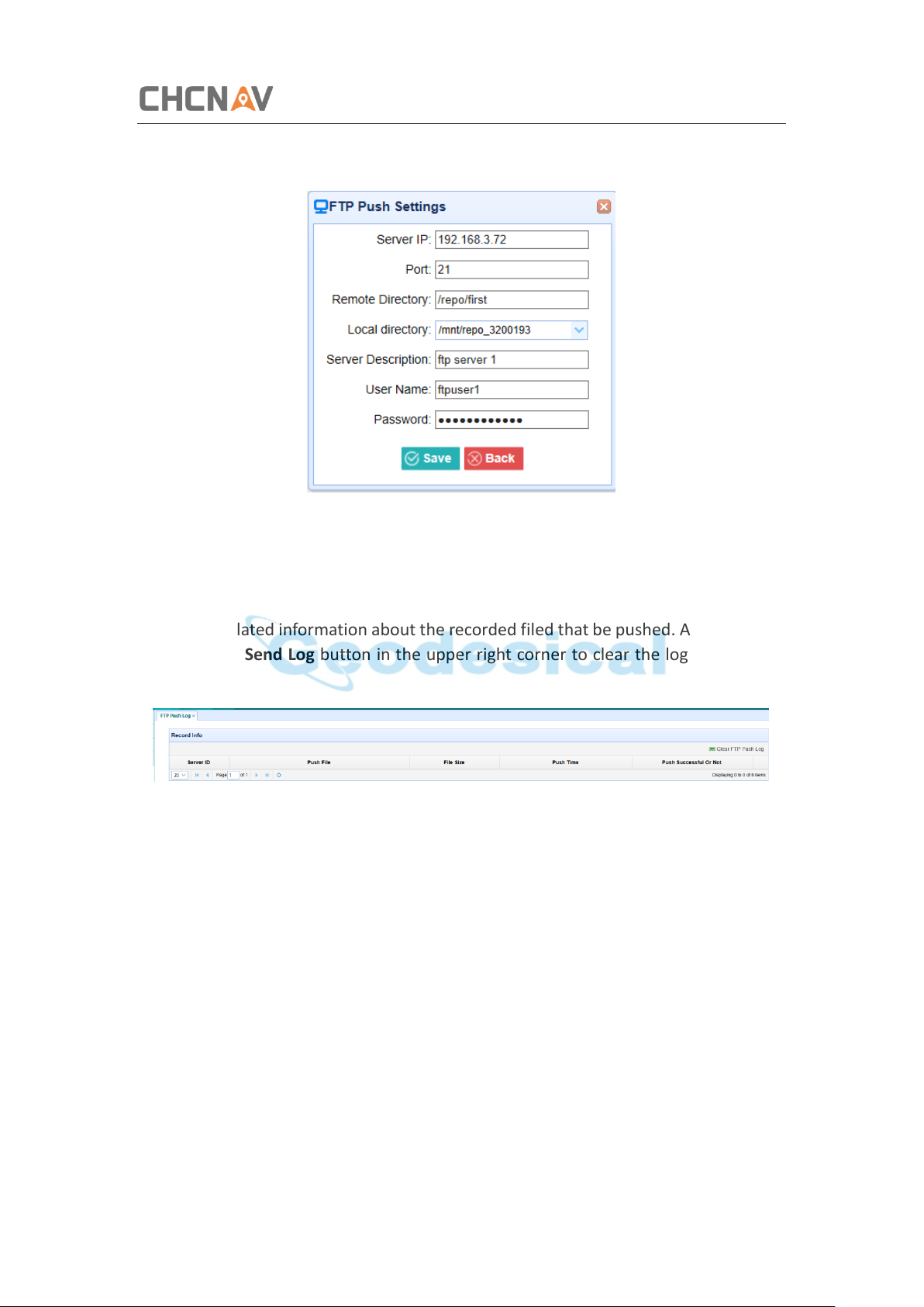
5.4.2 FTP Push Settings Submenu
Use this screen to configure the receiver to push stored files to the FTP server of your
choice. Only files that are configured to use FTP push are transmitted.
CHCNAV i50 GNSS USER GUIDE | 2018-11 P a g e | 45
Page 46
Configuring Through a Web Browser
Tap Modify button to the right of the required FTP server and the FTP Push Settings
screen appears:
5.4.3 FTP Push Log Submenu
Shows the related information about the recorded filed that be pushed. And users can
tap Clear Ftp Send Log button in the upper right corner to clear the log of FTP Push
operations.
5.4.4 Data Download Submenu
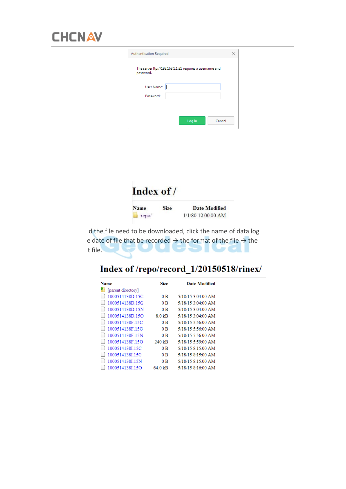
In this submenu, users can download the data files that recorded in the internal
storage through the internal FTP site.
1. Click this submenu, and then the log on dialogue box will prompt you to enter
a user name and password:
CHCNAV i50 GNSS USER GUIDE | 2018-11 P a g e | 46
Page 47
Configuring Through a Web Browser
The default logon account for the internal FTP site is:
➢ User name: ftp
➢ Password: ftp
2. Click the directory named as “repo” to view and download the files currently
stored on the receiver:
3. To find the file need to be downloaded, click the name of data logging session
→ the date of file that be recorded → the format of the file → the name of the
target file.
4. To download a file, left-click the name of the target file → download the file
according to the prompts.
CHCNAV i50 GNSS USER GUIDE | 2018-11 P a g e | 47
Page 48
Configuring Through a Web Browser
5.5 IO Settings Menu
Use the IO Settings menu to set up all receiver outputs and inputs. The receiver can
output CMR, RTCM, Raw data, Ephemeris data, GPGGA, GPGSV, on TCP/IP, UDP, serial
port, or Bluetooth ports.
5.5.1 IO Settings Submenu
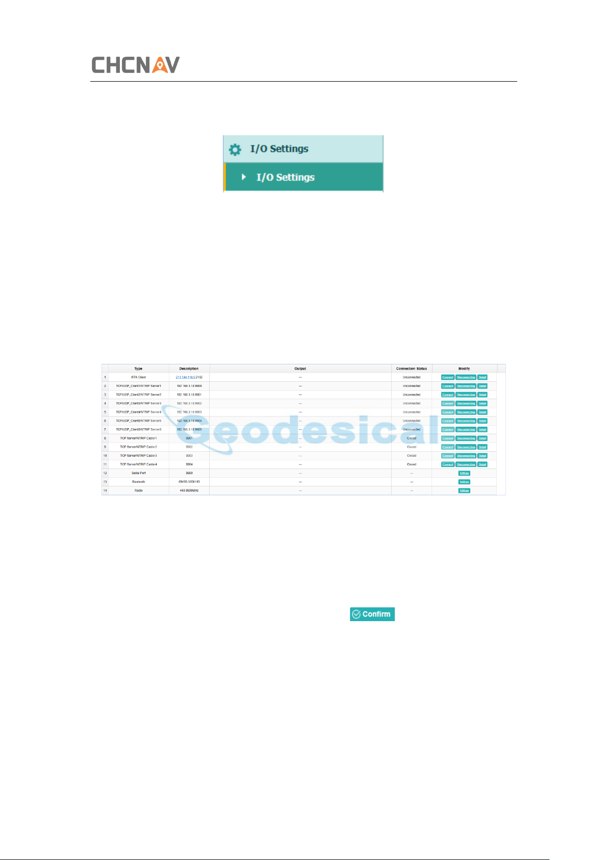
The following figure shows an example of the screen that appears when you select this
submenu.
In this submenu, users can configure 6 types of input and output settings.
1. RTK Client
After configuring the settings of RTK client, users can log on CORS or APIS. Tap
the Connect button to the right → the IO Settings screen will appear → choose
one of the connection protocols among the NTRIP, APIS_BASE and APIS_ROVER
→ configure the related parameters → click to log on CORS or APIS.
➢ Connection Protocol: NTRIP
CHCNAV i50 GNSS USER GUIDE | 2018-11 P a g e | 48
Page 49
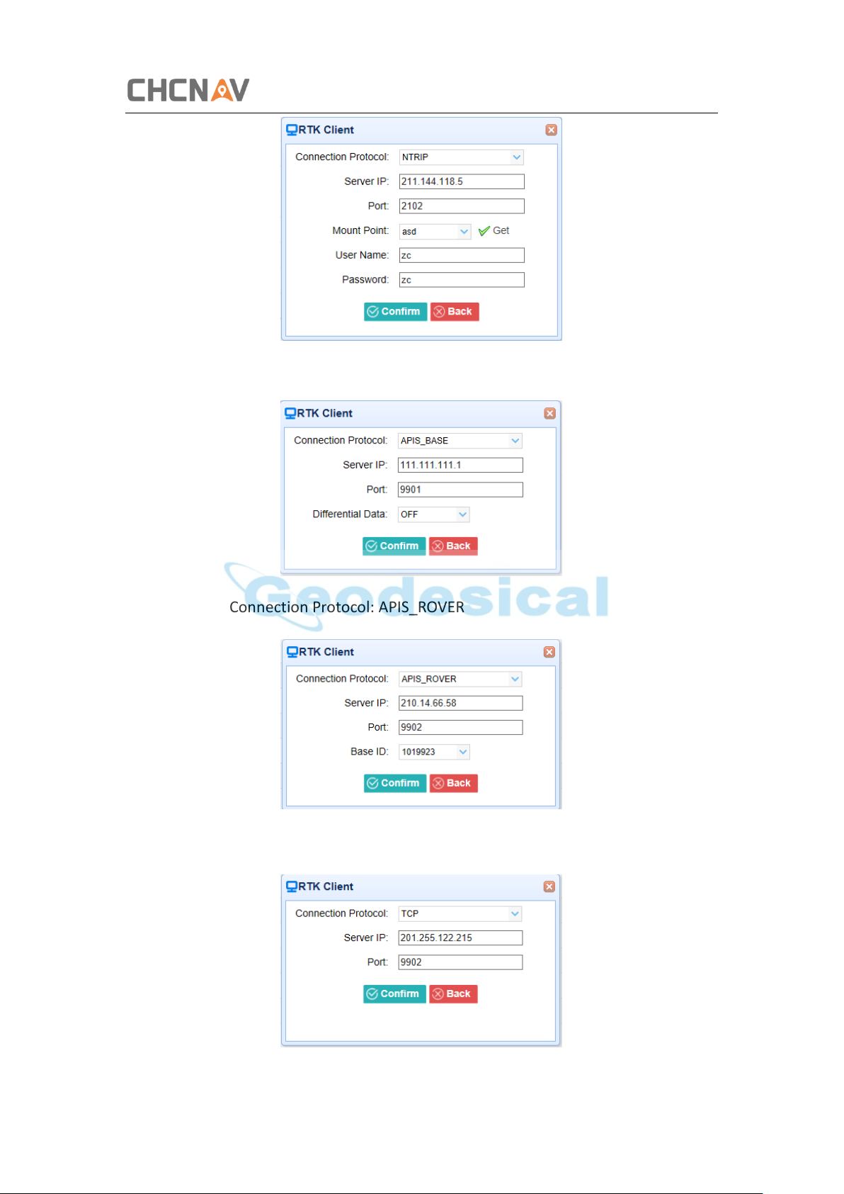
➢ Connection Protocol: APIS_BASE
Configuring Through a Web Browser
➢ Connection Protocol: APIS_ROVER
➢ Connection Protocol: TCP
CHCNAV i50 GNSS USER GUIDE | 2018-11 P a g e | 49
Page 50
Configuring Through a Web Browser
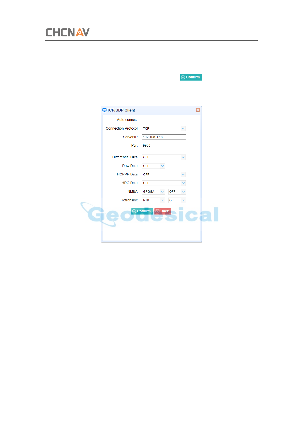
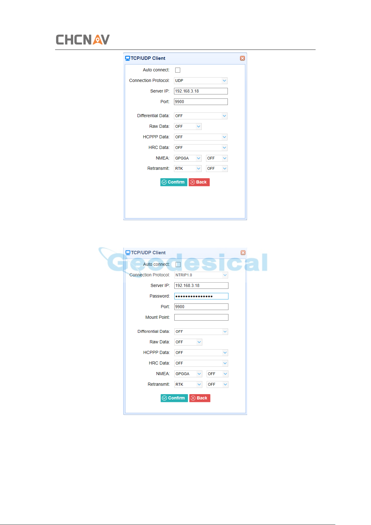
2. TCP/UDP/NTRIP
Tap the Connect button to the right of required TCP/UDP Client → the IO
Settings screen will appear → select the connection protocol between TCP and
UDP → enter the IP and Port of the target server → configure messages that
you want to output to the target server → click to save and complete
the connection.
➢ Connection Protocol: TCP
➢ Connection Protocol: UDP
CHCNAV i50 GNSS USER GUIDE | 2018-11 P a g e | 50
Page 51
Configuring Through a Web Browser
➢ Connection Protocol: NTRIP1.0
➢ Connection Protocol: NTRIP2.0
CHCNAV i50 GNSS USER GUIDE | 2018-11 P a g e | 51
Page 52
Configuring Through a Web Browser
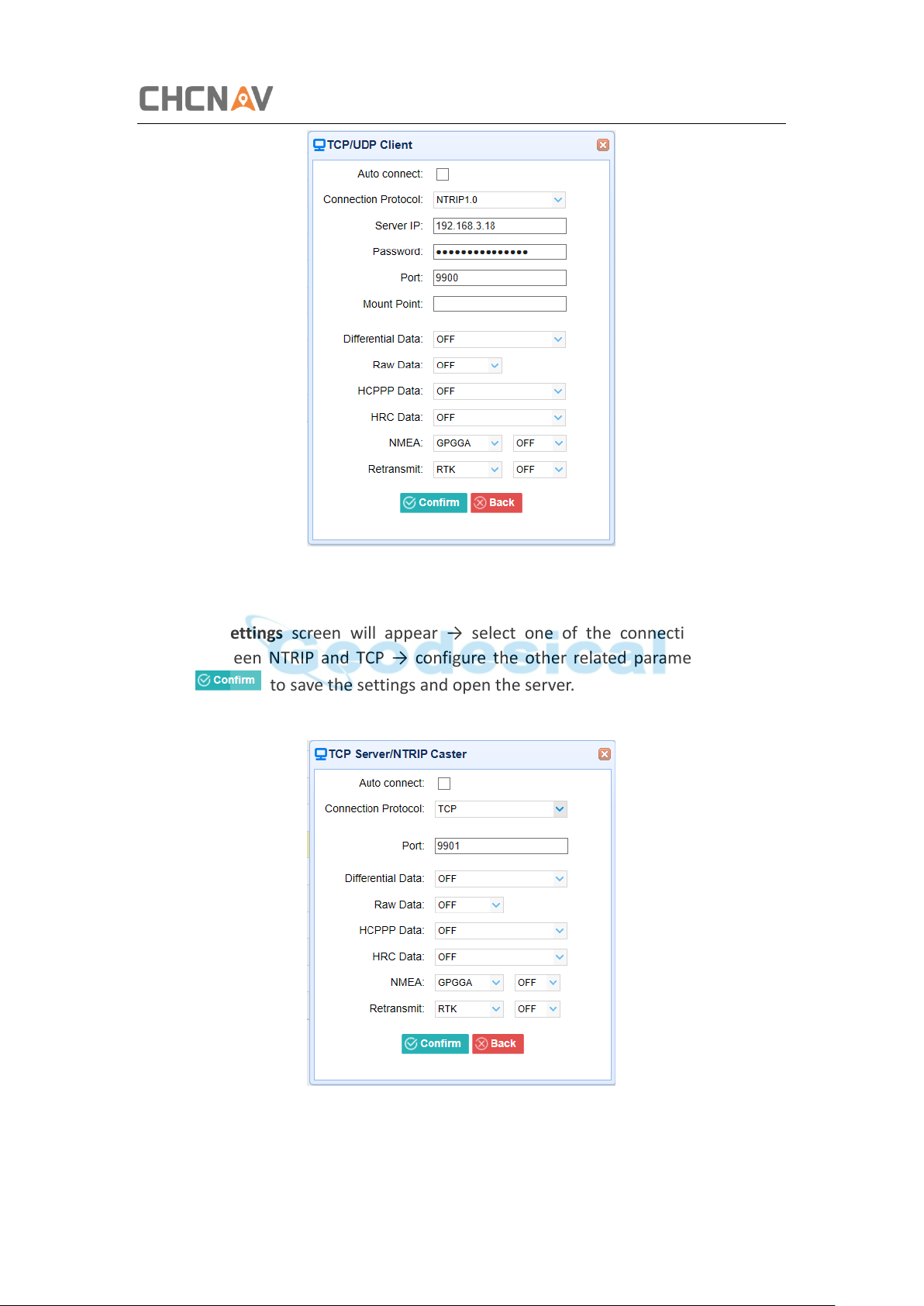
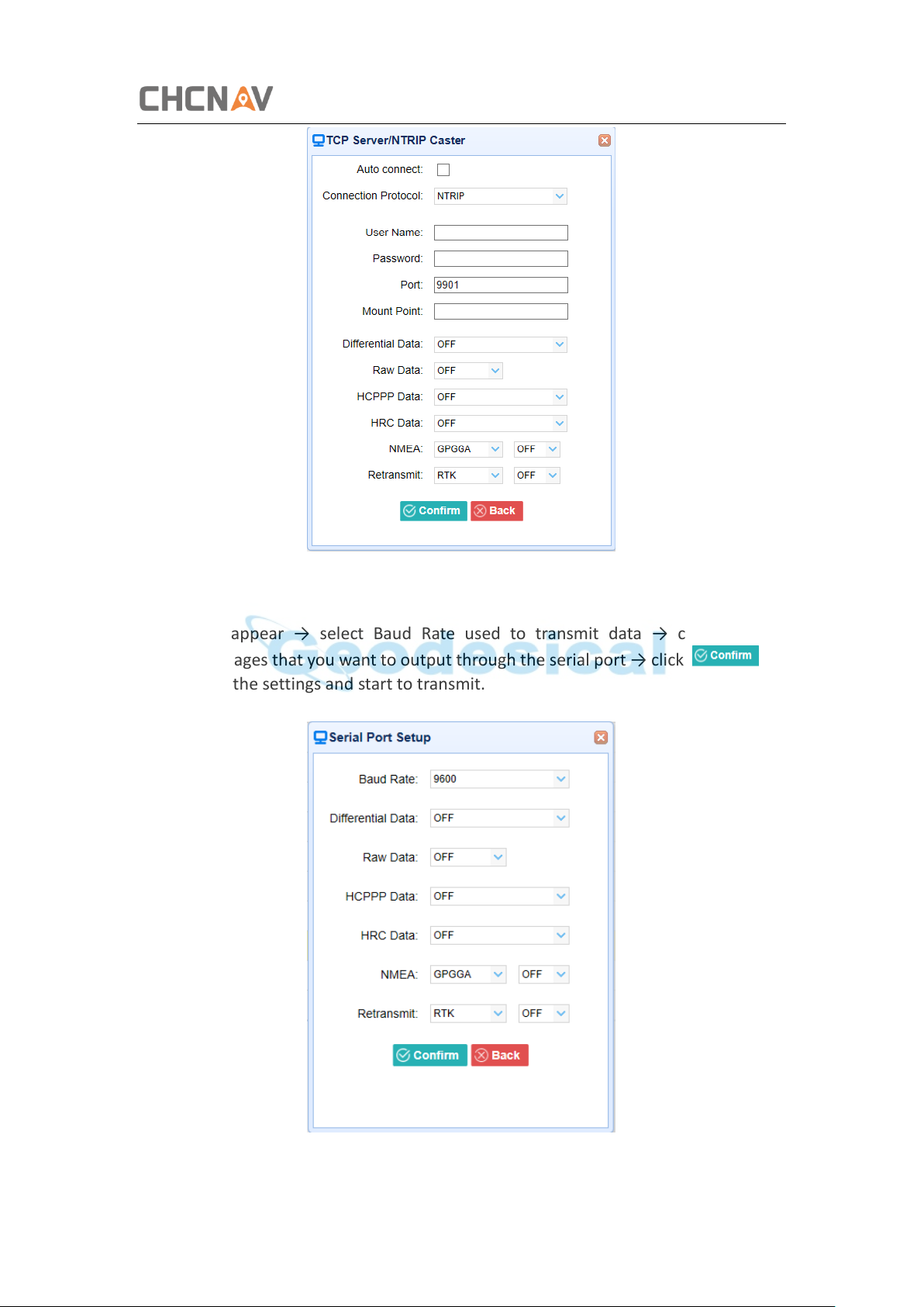
3. TCP Server/NTRIP Caster
Tap the Connect button to the right of required TCP Server/NTRIP Caster → the
IO Settings screen will appear → select one of the connection protocols
between NTRIP and TCP → configure the other related parameters → click
to save the settings and open the server.
➢ Connection Protocol: TCP
➢ Connection Protocol: NTRIP
CHCNAV i50 GNSS USER GUIDE | 2018-11 P a g e | 52
Page 53
Configuring Through a Web Browser
4. Serial Port
Tap the Settings button to the right of Serial Port → the Serial Port Setup screen
will appear → select Baud Rate used to transmit data → configure the
messages that you want to output through the serial port → click to
save the settings and start to transmit.
CHCNAV i50 GNSS USER GUIDE | 2018-11 P a g e | 53
Page 54
Configuring Through a Web Browser
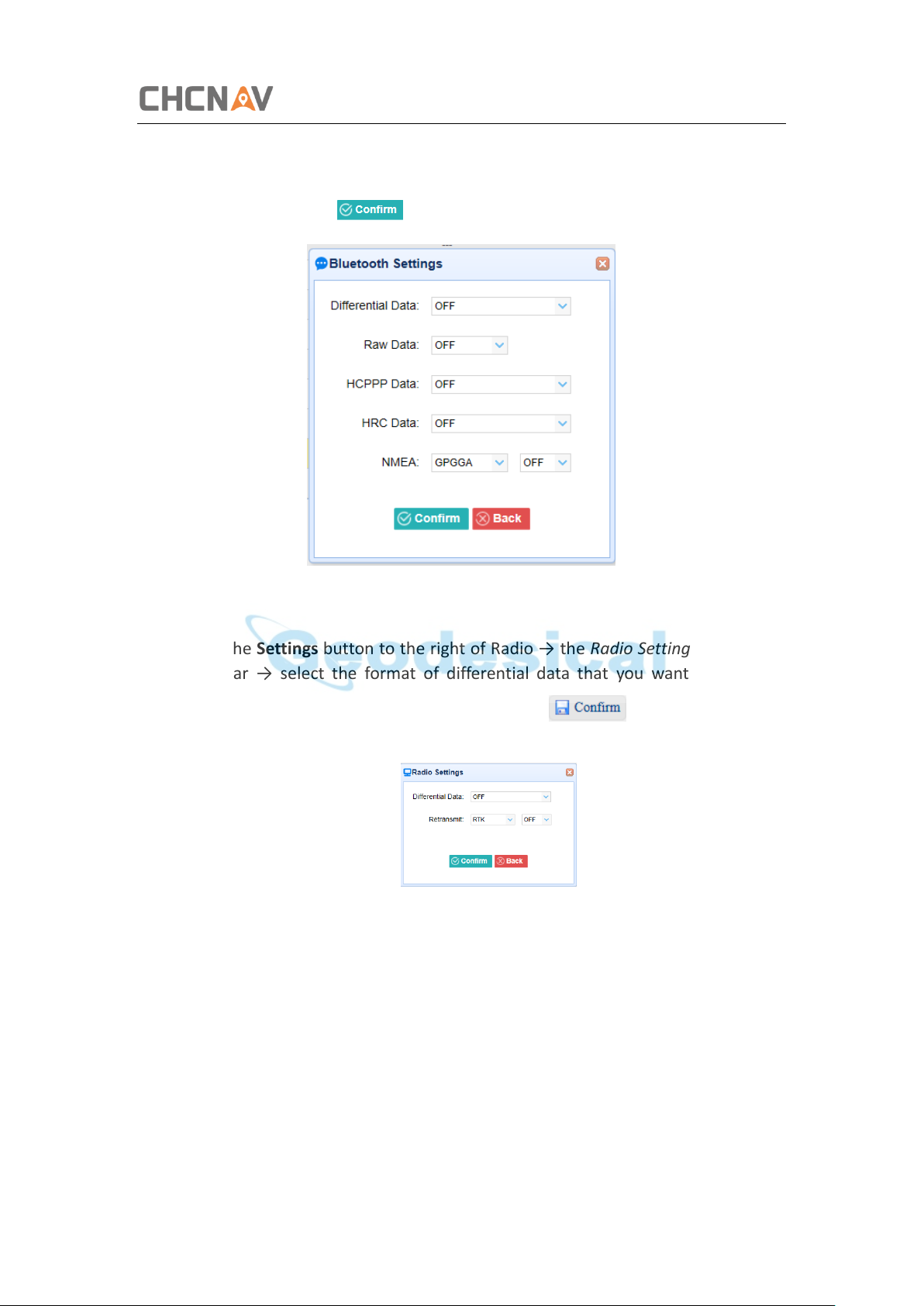
5. Bluetooth
Tap the Settings button to the right of Bluetooth → the Bluetooth Set screen
will appear → configure the messages that you want to transmit through
Bluetooth → click to save the settings and start to transmit.
6. Radio
Tap the Settings button to the right of Radio → the Radio Settings screen will
appear → select the format of differential data that you want to transmit
through radio from the dropdown list → click to save the settings
and start to transmit.
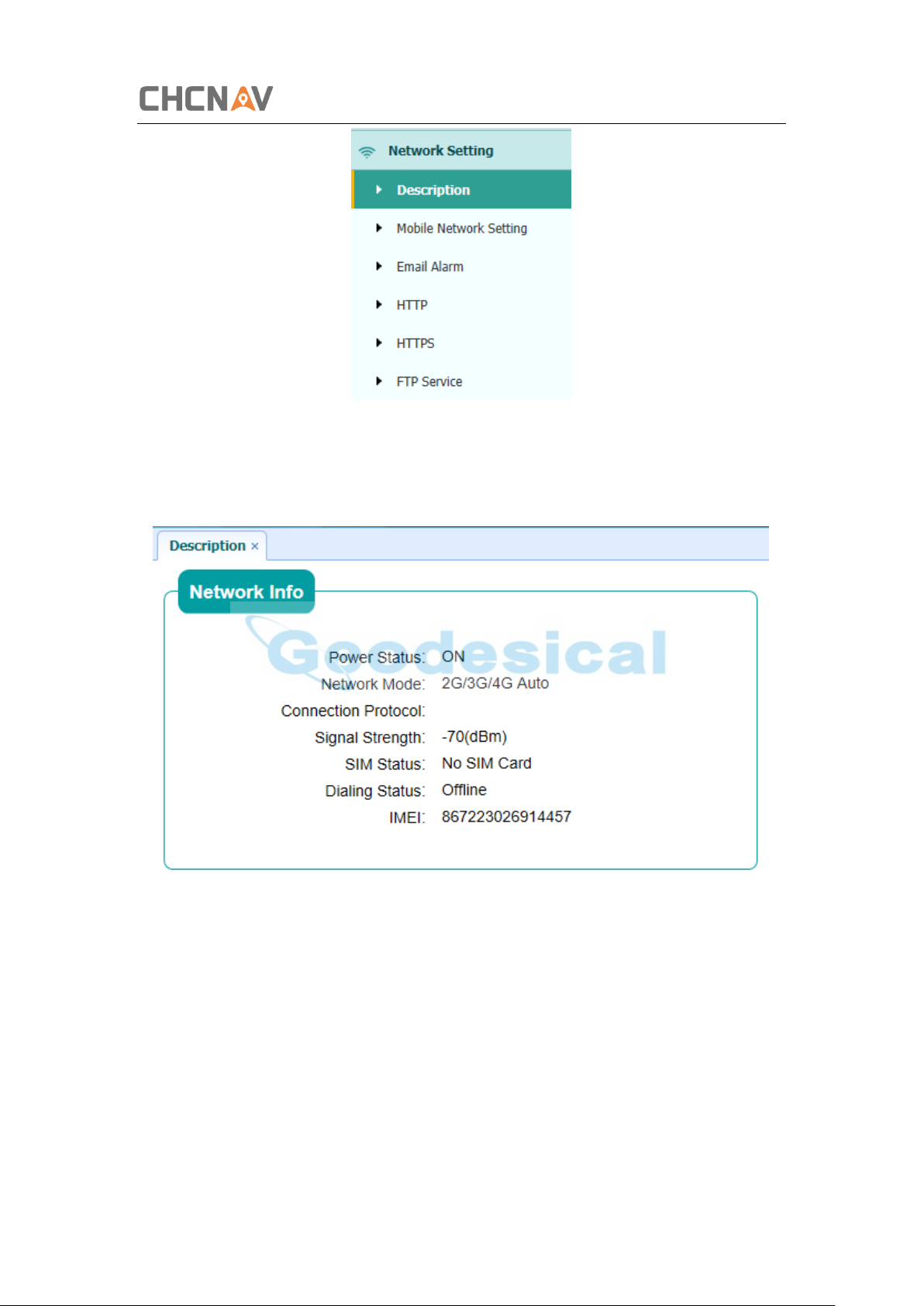
5.6 Network Setting Menu
Use this menu to view network information, configure the receiver’s mobile network,
set email alert for specific situation, configure HTTP or HTTPS port, and the user name
and password of internal FTP site:
CHCNAV i50 GNSS USER GUIDE | 2018-11 P a g e | 54
Page 55
Configuring Through a Web Browser
5.6.1 Description Submenu
Use this submenu to check the information of network setting.
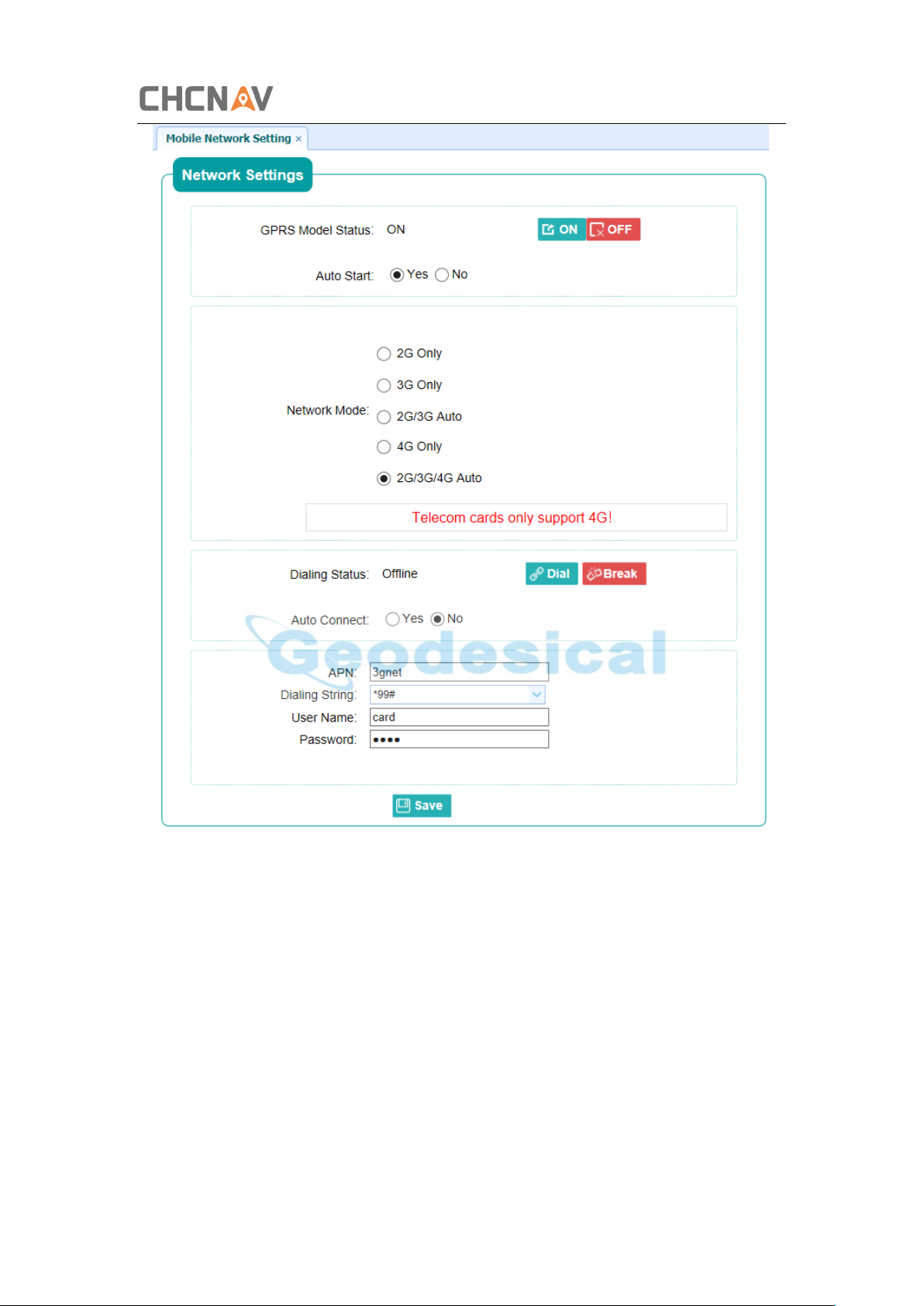
5.6.2 Mobile Network Setting Submenu
Use this submenu to configure GPRS model, network module and modify dialing status.
CHCNAV i50 GNSS USER GUIDE | 2018-11 P a g e | 55
Page 56
Configuring Through a Web Browser
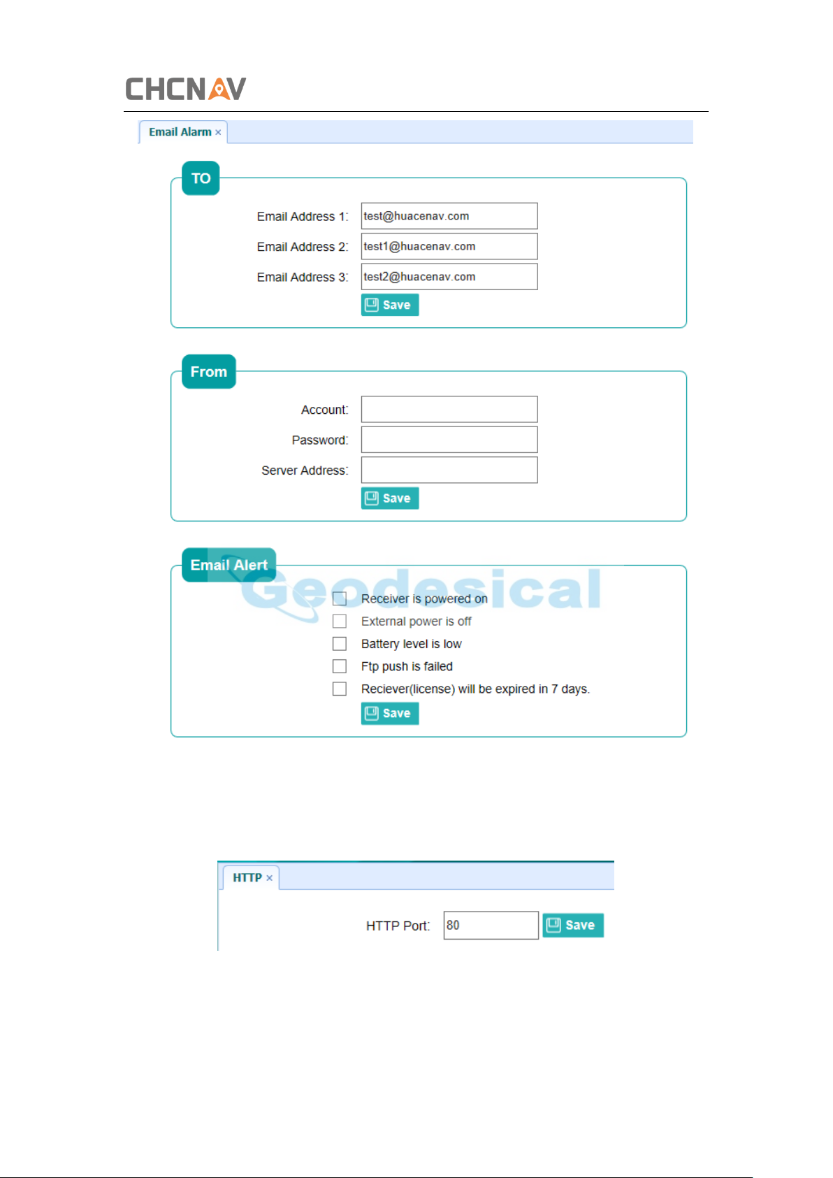
5.6.3 Email Alarm Submenu
Use this submenu to choose which situation of receiver will be alerted and input the
email address.
CHCNAV i50 GNSS USER GUIDE | 2018-11 P a g e | 56
Page 57
Configuring Through a Web Browser
5.6.4 HTTP Submenu
Use this submenu to configure HTTP port.
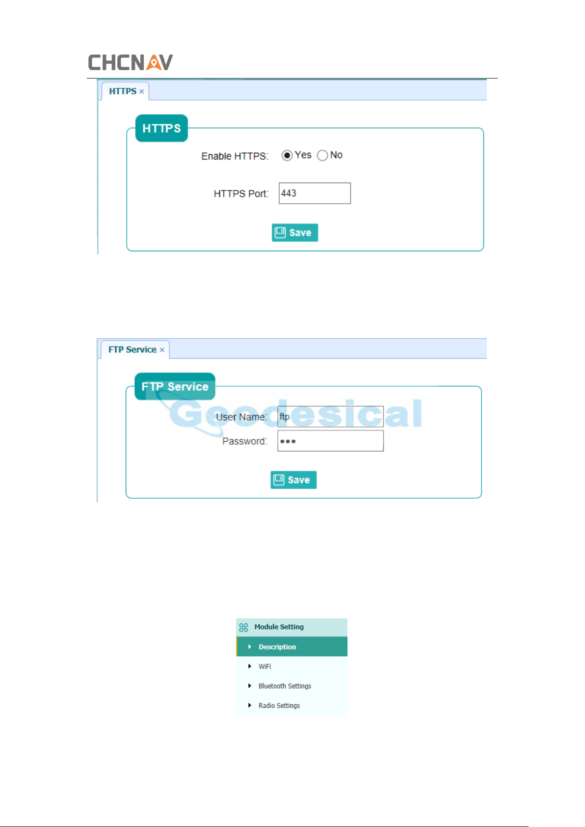
5.6.5 HTTPS Submenu
Use this submenu to configure HTTPS port.
CHCNAV i50 GNSS USER GUIDE | 2018-11 P a g e | 57
Page 58
Configuring Through a Web Browser
5.6.6 FTP Service Submenu
Use this submenu to configure the user name and password of internal FTP site.
5.7 Module Setting Menu
Use this menu to check module information, configure WiFi, bluetooth, radio related
settings, and turn on/off static voice of buzzer:
CHCNAV i50 GNSS USER GUIDE | 2018-11 P a g e | 58
Page 59
Configuring Through a Web Browser
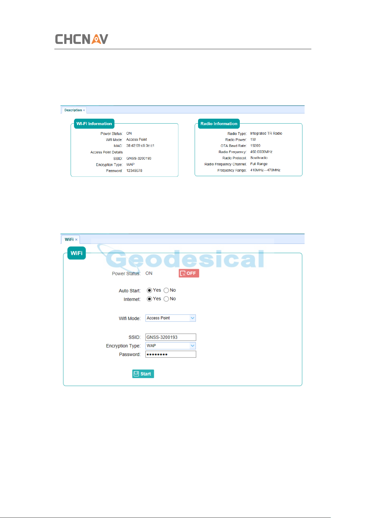
5.7.1 Description Submenu
Use this submenu to check the information of WiFi module, bluetooth module and
radio module.
5.7.2 WiFi Submenu
Use this submenu to turn on/off WiFi function and modify password.
5.7.3 Bluetooth Settings Submenu
Use this submenu to turn on/off bluetooth function and modify PIN number.
CHCNAV i50 GNSS USER GUIDE | 2018-11 P a g e | 59
Page 60
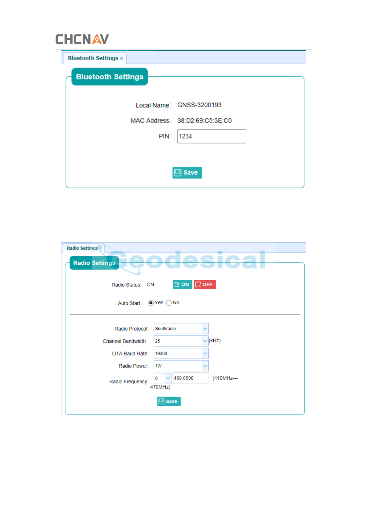
5.7.4 Radio Settings Submenu
Configuring Through a Web Browser
Use this submenu to turn on/off radio function and configure radio parameters.
CHCNAV i50 GNSS USER GUIDE | 2018-11 P a g e | 60
Page 61
Configuring Through a Web Browser
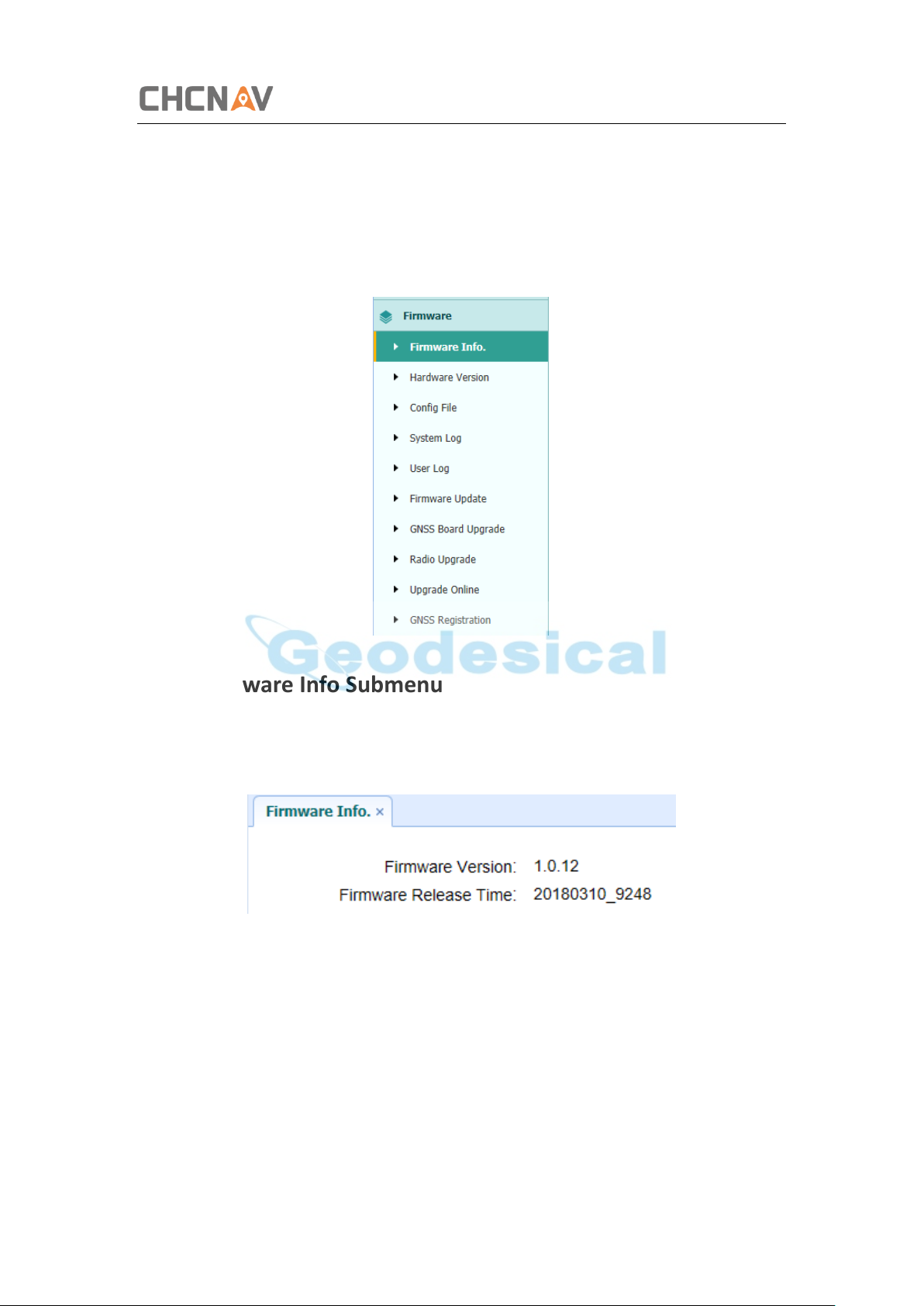
5.8 Firmware Menu
Use this menu to check the current firmware information, download the system log,
update the receiver firmware, download or update the configuration file and register
the receiver, and more:
5.8.1 Firmware Info Submenu
Use this submenu to check the current firmware information. The following figure
shows an example of the firmware information.
5.8.2 Hardware Version Submenu
Use this submenu to check the hardware information, including main board version
and core board version:
CHCNAV i50 GNSS USER GUIDE | 2018-11 P a g e | 61
Page 62
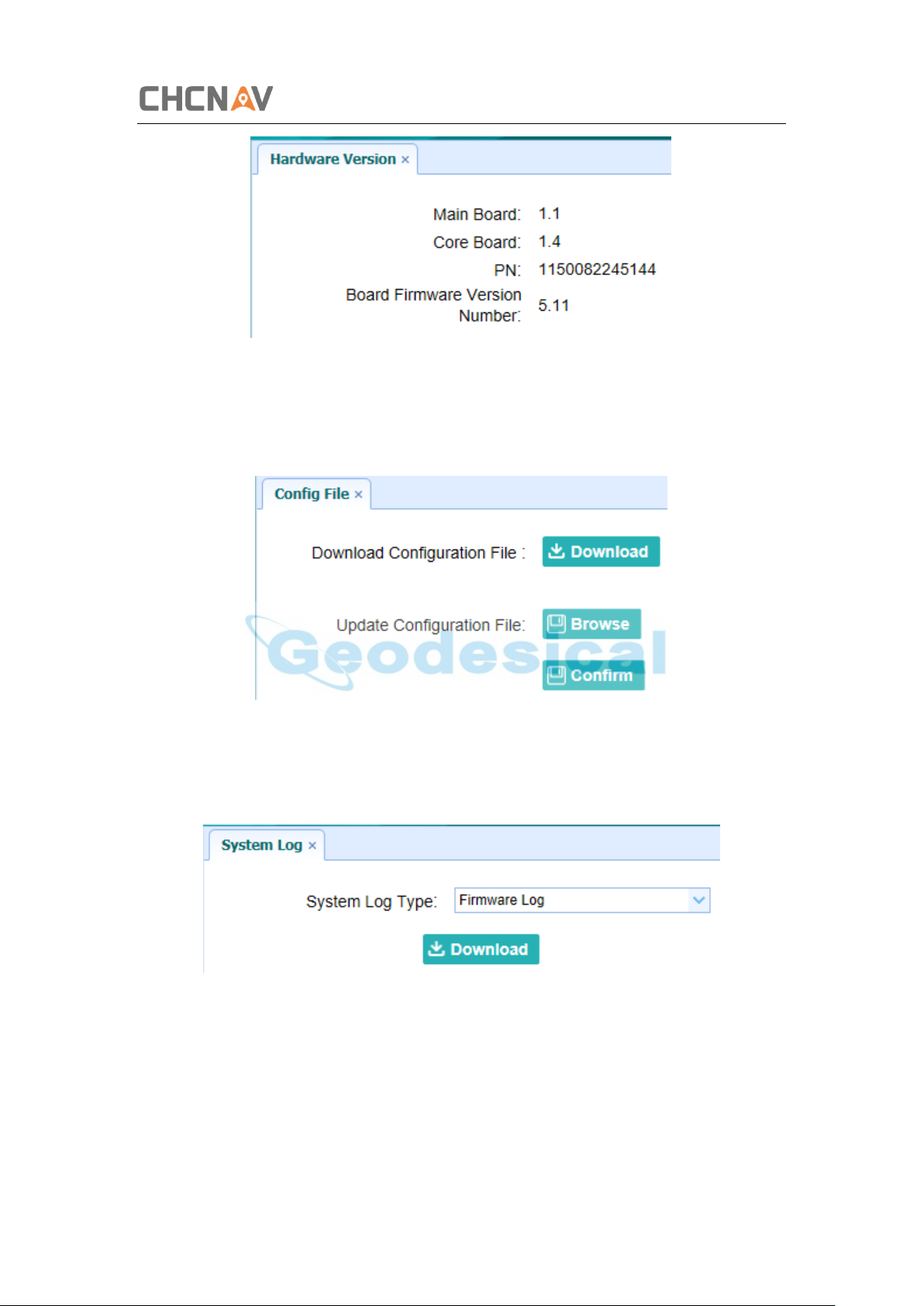
5.8.3 Config File Submenu
Use this submenu to update Configuration File.
Configuring Through a Web Browser
5.8.4 System Log Download Submenu
Use this submenu to download the system log of the receiver.
CHCNAV i50 GNSS USER GUIDE | 2018-11 P a g e | 62
Page 63
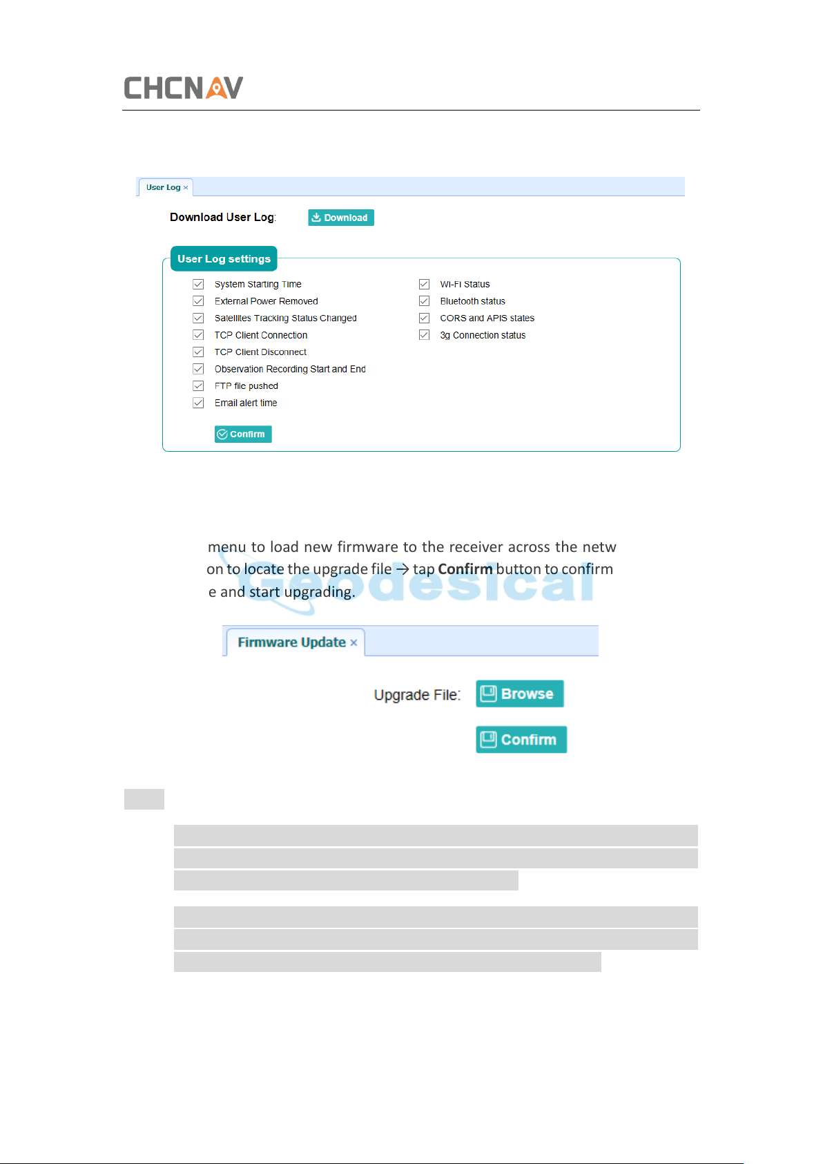
5.8.5 User Log Submenu
Configuring Through a Web Browser
5.8.6 Firmware Update Submenu
Use this submenu to load new firmware to the receiver across the network. Tap the
Browse button to locate the upgrade file → tap Confirm button to confirm the selected
upgrading file and start upgrading.
Notes
• It may take about 3 or 4 minutes to complete the firmware upgrading. Do not
touch the power button or unplug the power until the upgrading process is
finished, or damage will be caused to the receiver.
• The receiver will restart after the firmware upgrading is done, so users need to
reconnect the receiver with your computer via Wi-Fi, and then log-in the
receiver through a web browser to continue the configuration.
CHCNAV i50 GNSS USER GUIDE | 2018-11 P a g e | 63
Page 64
Configuring Through a Web Browser
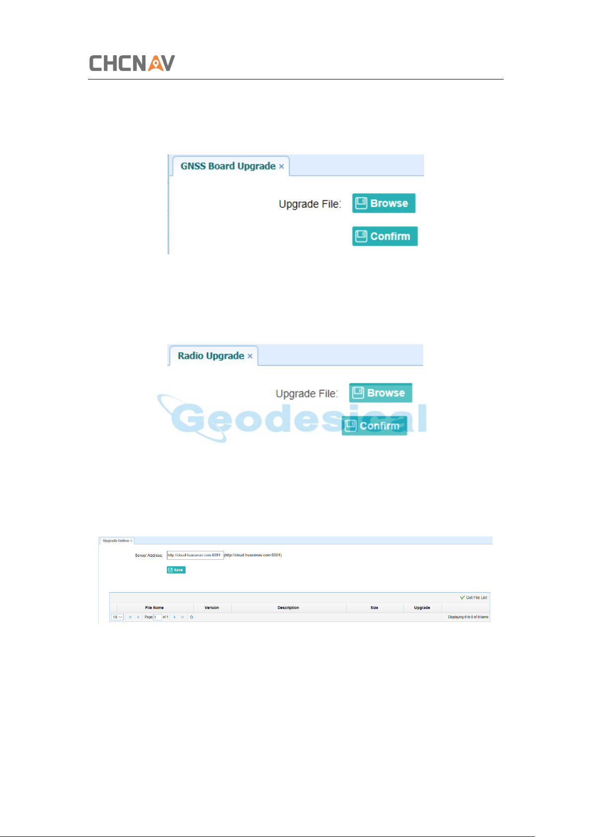
5.8.7 GNSS Board Upgrade Submenu
Use this submenu to upgrade GNSS Board.
5.8.8 Radio Upgrade Submenu
Use this submenu to browse upgrade file and upgrade radio.
5.8.9 Upgrade Online Submenu
Use this submenu to input Server Address and upgrade online.
5.8.10 GNSS Registration Submenu
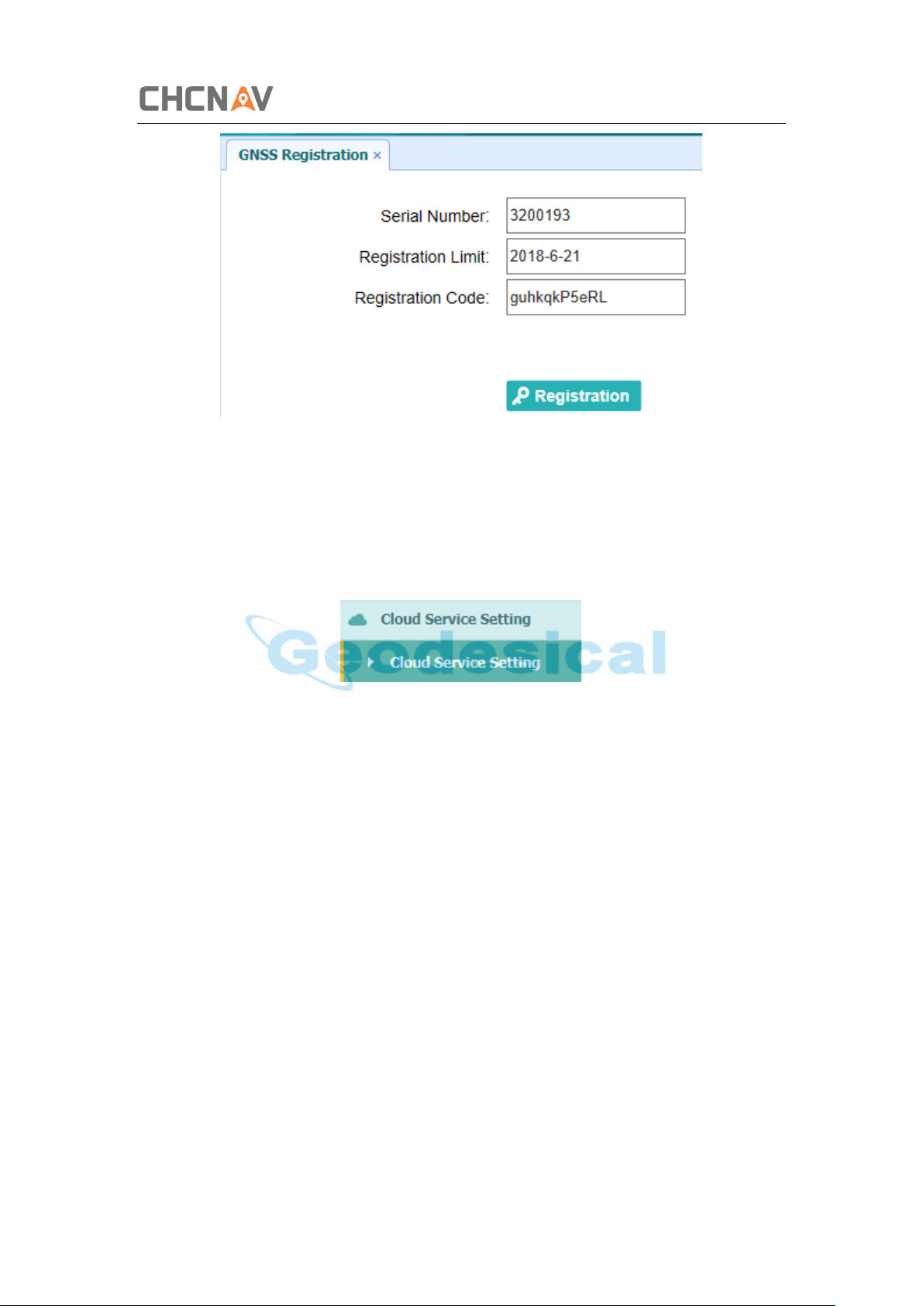
Use this submenu to register the receiver. Paste or enter the registration code to the
Registration Code field → tap Registration button to complete the registration.
CHCNAV i50 GNSS USER GUIDE | 2018-11 P a g e | 64
Page 65
5.9 Cloud Service Setting Menu
Configuring Through a Web Browser
5.9.1 Cloud Service Setting Submenu
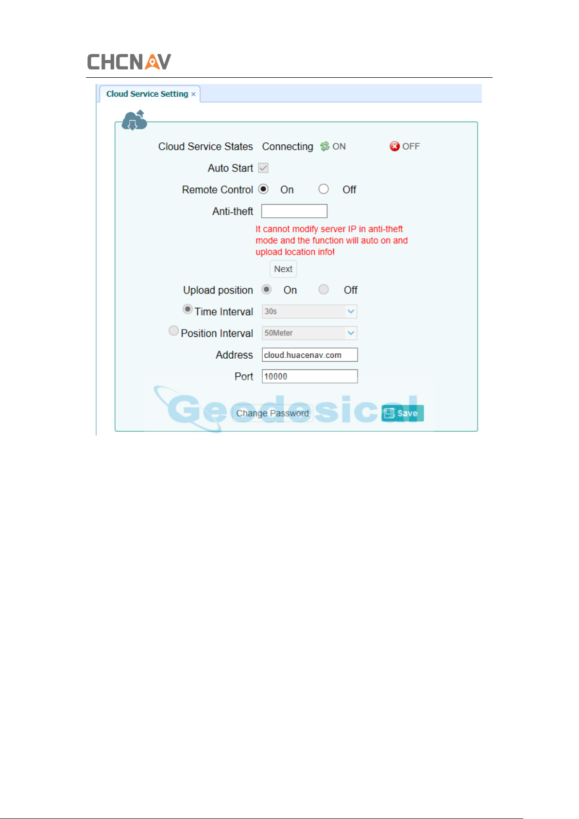
Use this submenu to turn on or turn off Cloud Service, Auto Start, Remote Control and
configure other settings .
CHCNAV i50 GNSS USER GUIDE | 2018-11 P a g e | 65
Page 66
Configuring Through a Web Browser
CHCNAV i50 GNSS USER GUIDE | 2018-11 P a g e | 66
Page 67
Communication Ports Definition
PIN
FUNCTION
1
Ground ( - )
2
Ground ( - )
3
RS232-TX (Output)
4
PPS
5
Not Used
6
VIN
7
RS232-RX (Input)
A Communication Ports Definition
AI CHC i50 Receiver IO Port (7-pin Lemo Port) Definition
CHCNAV i50 GNSS USER GUIDE | 2018-11 P a g e | 67
Page 68

CHC Navigation
Building D, NO. 599 Gaojing Road,
Qingpu District, 201702 Shanghai, China
Tel: +86 21 542 60 273 | Fax: +86 21 649 50 963
Email: [email protected] | [email protected]
Skype: chcnav_support
Website: www.chcnav.com
Make your work more efficient
 Loading...