

CHCNAV CHC CTS-112R4 User Manual

CHC® CTS-112R4
User Manual
Version 1.0
English
Table of content
1. Features ............................................................................................................................ 5
2. Cautions ............................................................................................................................ 6
3. Safety guide ....................................................................................................................... 7
4. Description of the instrument ............................................................................................ 8
4.1. Instrument components .................................................................................................. 8
4.2. Keyboard description ....................................................................................................... 9
4.3. Functional keys .............................................................................................................. 11
4.4. Star (★) key mode.......................................................................................................... 13
5. Description of the instrument .......................................................................................... 14
5.1. Power On/Off ................................................................................................................. 14
5.2. Setting of tilt correction on vertical and horizontal angles ........................................... 14
5.3. Setting distance measurement mode ............................................................................ 16
5.4. Setting of tilt correction on vertical and horizontal angles ........................................... 16
5.5. Reflecting signal ............................................................................................................. 17
5.6. Setting atmospheric correction ..................................................................................... 18
5.6.1. Setting the atmospheric correction value directly .............................................. 18
5.6.2. Calculating the atmospheric correction based on temperature and pressure ... 19
5.7. Correction on atmospheric refraction error and earth curvature ................................. 20
5.8. Setting minimum reading of setting angle/distance ..................................................... 20
5.9. Setting auto power OFF ................................................................................................. 22
5.10. Setting instrument constant .......................................................................................... 23
5.11. Select a code file ............................................................................................................ 24
6. Preparation for measurements ........................................................................................ 25
6.1. Unpacking and storage of instrument ........................................................................... 25
6.2. Instrument setup ........................................................................................................... 25
6.2.1. Leveling and Centering the Instrument by plumb bob ....................................... 25
6.2.2. Centering by using the laser plummet ................................................................ 26
6.3. Loading, unloading, charging the battery and its information ...................................... 27
6.4. Reflecting prism ............................................................................................................. 28
6.5. Mounting and dismounting instrument from tribrach .................................................. 28
6.6. Eyepiece adjustment and collimating object ................................................................. 29
6.7. Method of inputting, alphanumeric characters ............................................................ 29
7. Angles measurements ..................................................................................................... 31
7.1. Measuring horizontal and vertical angles ...................................................................... 31
7.2. Shift the horizontal angle (right/left) ............................................................................. 32
7.3. Setting horizontal angle ................................................................................................. 32
7.3.1. Setting by [HOLD] ................................................................................................ 32
7.3.2. Setting by Inputting through the Keyboard ........................................................ 33
7.4. Shift between V angle and V% ....................................................................................... 34
7.5. Repetitious angle measurement .................................................................................... 35
7.6. Shift between azimuth and vertical angle ..................................................................... 37
CHC CTS-112R4 user manual 2
8. Distance measurements .................................................................................................. 38
8.1. Distance measurements ................................................................................................ 38
8.2. Setting measurement mode .......................................................................................... 39
8.3. Stakeout ......................................................................................................................... 40
8.4. Offset measurement ...................................................................................................... 41
8.4.1. Angle offset ......................................................................................................... 41
8.4.2. Distance offset .................................................................................................... 43
8.4.3. Plane offset ......................................................................................................... 45
8.4.4. Column offset ...................................................................................................... 47
9. Coordinates measurements ............................................................................................. 50
9.1. Procedure of coordinates measurements ..................................................................... 50
9.2. Setting coordinates of occupied point ........................................................................... 52
9.3. Setting the instrument height ........................................................................................ 53
9.4. Setting the target height ................................................................................................ 54
10. Data collection ................................................................................................................. 55
10.1. Operation procedure ..................................................................................................... 55
10.2. Selecting a file for data collection .................................................................................. 56
10.3. Occupied point and backsight point .............................................................................. 56
10.3.1. Example for setting the occupied point ............................................................ 57
10.4. Data collect offset measurement mode ........................................................................ 57
10.4.1. Angle offset measurement ............................................................................... 58
10.4.2. Distance offset measurement........................................................................... 60
10.4.3. Plane offset measurement ............................................................................... 61
10.4.4. Column offset measurement ............................................................................ 64
10.5. Setting config of data collection .................................................................................... 66
11. Stakeout .......................................................................................................................... 67
11.1. Stakeout procedure ....................................................................................................... 67
11.2. Preparation .................................................................................................................... 67
11.2.1. Setting the grid factor ....................................................................................... 67
11.2.2. Selecting coordinate data file ........................................................................... 68
11.2.3. Setting occupied point ...................................................................................... 68
11.2.4. Setting backsight point ..................................................................................... 69
11.3. Setting a new point ........................................................................................................ 70
11.3.1. Side shot method .............................................................................................. 70
11.3.2. Resection method ............................................................................................. 71
12. Measurement program mode .......................................................................................... 75
12.1. Remote height measurement (REM) ............................................................................. 75
12.1.1. Known prism height (e.g. H = 1.3 m) ................................................................ 75
12.1.2. When prism height is unknown ........................................................................ 77
12.2. Tie distance .................................................................................................................... 78
12.2.1. MLM-1 (A-B, A-C) .............................................................................................. 79
12.2.2. Using coordinate file ......................................................................................... 81
12.3. Set Z coordinate of occupied point ................................................................................ 82
CHC CTS-112R4 user manual 3

12.3.1. Set Z coordinate occupied point using coordinate data file ............................. 82
12.3.2. Set Z coordinate of occupied point without coordinate data file..................... 84
12.4. Area calculation ............................................................................................................. 85
12.4.1. Area calculation from coordinate data file ....................................................... 85
12.4.2. Change the display unit .................................................................................... 86
12.5. Measurement REOM point to line ................................................................................. 87
13. Parameters ...................................................................................................................... 89
14. Memory management ..................................................................................................... 90
14.1. File maintains ................................................................................................................. 90
14.1.1. Setting the atmospheric correction value directly ........................................... 90
14.1.2. Create a new file ............................................................................................... 91
14.1.3. Renaming a file ................................................................................................. 91
14.1.4. Delete a file ....................................................................................................... 92
14.2. File output ...................................................................................................................... 92
14.3. Data transfer .................................................................................................................. 93
14.4. Load data ....................................................................................................................... 94
15. Check and adjustment ..................................................................................................... 95
15.1. Bubble level ................................................................................................................... 95
15.2. Circular level .................................................................................................................. 95
15.3. Adjustment of reticle ..................................................................................................... 95
15.4. Perpendicularity of the line of sight to horizontal axis (2C) .......................................... 96
15.5. Vertical index difference compensation ........................................................................ 98
15.6. Adjustments of vertical index difference (I angle) and vertical angle 0 datum ............. 98
15.7. Transverse axis error compensation adjustment ......................................................... 100
15.8. Optical plummet .......................................................................................................... 101
15.9. Instrument constant (K) ............................................................................................... 102
15.10. Parallel between line of sight and emitting photoelectric axis .................................. 103
15.11. Reflectorless EDM ....................................................................................................... 103
15.12. Tribrach leveling screw ............................................................................................... 104
15.13. Related parts for reflector .......................................................................................... 104
CHC CTS-112R4 user manual 4

1. Features
Makes fieldwork easier
Dual face keyboards with buttons illumination to minimize mistakes provides optimum viewing and
convenience under any environmental conditions. Starkey button [★] immediately brings up necessary
functions. Built-in laser plummet is equipped for quick instrument setup in all lighting conditions.
Enables cable-free connection like mini-USB, SD as well as serial ports.
Better EDM performance
The CTS-112R 4 is one of the fastest total station in his class, with a distance measurement speed of 0.3
seconds. Reflectorless range is up to 400 m and distance measurement to single prism is 5000 m.
Absolute encoding disk
With absolute encoding disk, you can start your work directly as the instrument is powered on. Azimuth
angle will be saved even if the power is off incidentally in the job.
Large memory size
Internal memory can store 30 000 points, however external SD card supports maximum 32 GB memory
that can record 245 760 000 points.
Special surveying programs
Besides of ordinary surveying programs, such series of total station also has special surveying programs,
such as remote height measurement, offset measurement, remote distance measurement, stake out,
resection, area calculation, road design and stake out, etc., which are enough to meet the needs of
professional measurement and surveying measurement.
CHC CTS-112R4 user manual 5

CAUTION
1) Do not collimate the objective lens direct to sunlight without a filter.
2) Do not store the instrument in high and low temperature to avoid the sudden or great
change of temperature.
3) When the instrument is not in use, place it in the case and avoid shock, dust and
humidity.
4) If there is great difference between the temperature in work site and that in store place,
you should leave the instrument in the case till it adapts to the temperature of
environment.
5) If the instrument has not been used for a long time, you should remove the battery for
separate storage. The battery should be charged once a month.
6) When transporting the instrument should be placed in carrying case, it is recommended
that cushioned material should be used around the case for support.
7) For less vibration and better accuracy, the instrument should be set up on a wooden
tripod rather than an aluminum tripod.
8) Clean exposed optical parts with degreased cotton or less tissue only!
9) Clean the instrument surface with a woolen cloth after use. If it gets wet, dry it
immediately.
10) Before opening, inspect the power, functions and indications of the instrument as well as
initial setting and correction parameters.
11) Unless the user is a maintenance specialist, do not attempt to disassemble the
instrument by yourself even if you find the instrument abnormal.
12) The CTS-112R4 is reflectorless total station and emits visible laser. Do not shoot at eyes.
2. Cautions
CHC CTS-112R4 user manual 6

WARNING
The total station is equipped with an EDM of a laser grade of 3R/a. It is verified by the
following labels. On the vertical tangent screw sticks an indication label “CLASS III LASER
PRODUCT”. A similar label is stick on the opposite side. This product is classified as Class 3R
laser product, which accords to the following standards. IEC60825-1:2001 “SAFETY OF LASER
PRODUCTS”. Class 3R/a laser product: It is harmful to observe laser beam continuously. User
should avoid sighting the laser at the eyes. It can reach 5 times the emitting limit of Class2/II
with a wavelength of 400 mm-700 mm.
WARNING
Continuously looking straight at the laser beam is harmful.
Prevention:
Do not stare at the laser beam or point the laser beam to other’s eyes. Reflected laser beam
is a valid measurement to the instrument.
WARNING
When the laser beam emits on prism, mirror, metal surface, window, etc., it is dangerous to
look straight at the reflex.
Prevention:
Do not stare at the object which reflects the laser beam. When the laser is switched on
(under EDM mode), do not look at it on the optical path or near the prism. It is only allowed
to observe the prism with the telescope of total station.
WARNING
Improper operation on laser instrument of Class 3R will bring dangers.
Prevention:
To avoid being harmed, each user is required to take safety precautions, and take everything
under control within the distance that would incur dangers (according to IEC60825-1:2001).
Harmful distance means the maximum distance between the start point and the point which
the laser is weakened to a degree that doesn’t harm people.
3. Safety guide
The following shows the explanation related to the key sections of the Standard. Laser instrument of
Class 3R is applicable outdoors and in construction field (measurement, defining lines, leveling).
• Only those persons who are trained with related course and authenticated can install, adjust, and
operate this kind of laser instrument.
• Stand related warning symbols in the scale of use.
• Prevent any person to look straight at or use optical instrument to observe the laser beam.
• To prevent the harm caused by laser, block the laser beam at the end of the working route.
• When the laser beam exceeds the limit area (harmful distance) and when there are motivating
persons, stopping the laser beam is a must.
• The optical path of the laser should be set higher or lower than the line of sight.
• When the laser instrument is not in use, take care of it properly. The person who is not
authenticated is not allowed to use.
• Prevent the laser beam from irradiating plane mirror, metal surface, window, etc.; especially beware
of the surface of plane mirror and concave mirror.
CHC CTS-112R4 user manual 7
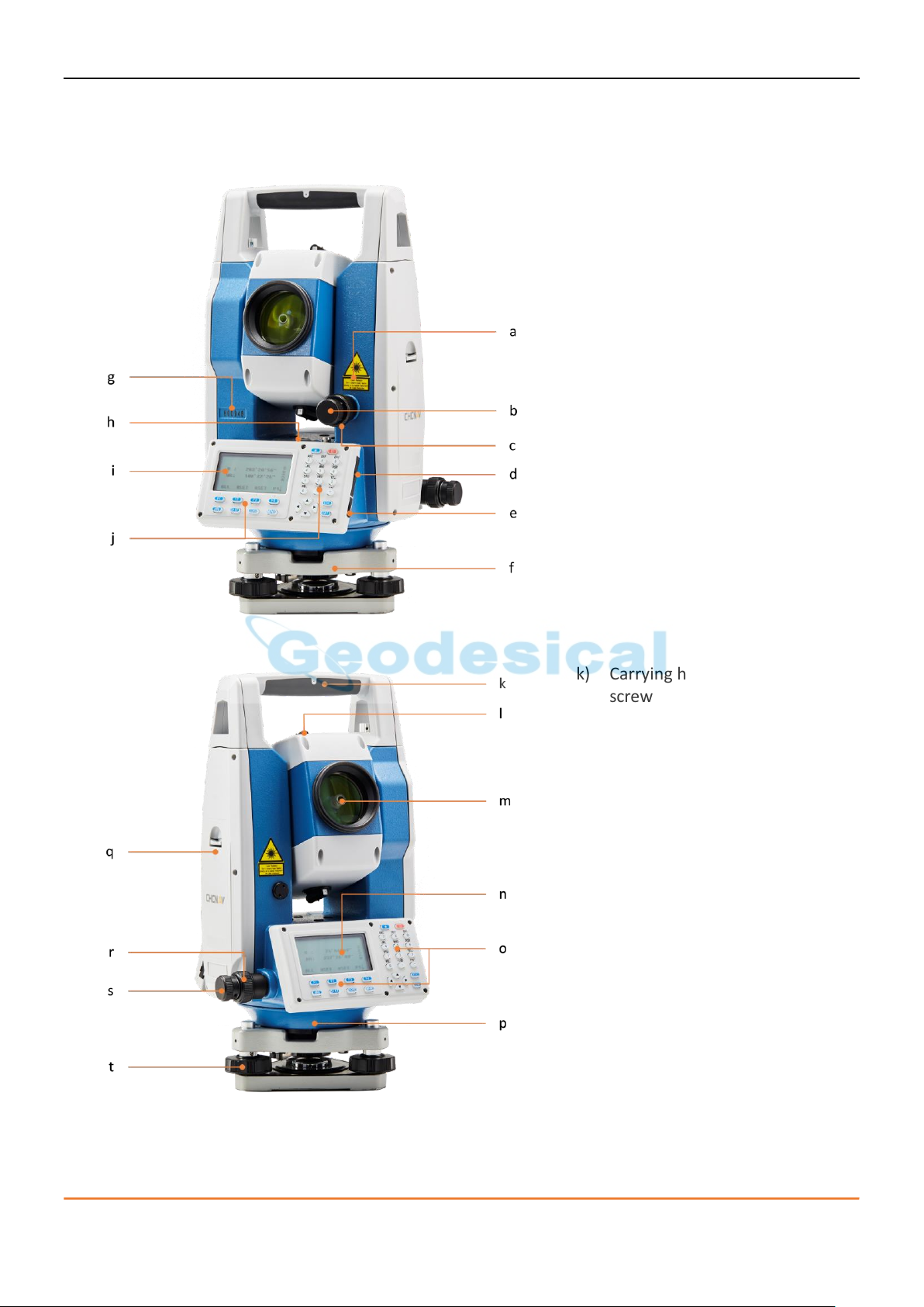
a) Laser class label
b) Vertical drive
c) Vertical clamp
d) SD card port
e) Mini-USB interface
f) Tribrach
g) Instrument serial number
h) Bubble level
i) I Face display
j) I Face keyboard
k) Carrying handle with mounting
screw
l) Optical sight
m) Objective with integrated EDM
n) II Face display
o) II Face keyboard
p) Laser plummet
q) Battery cover
r) Horizontal clamp
s) Horizontal drive
t) Leveling screw
4. Description of the instrument
4.1. Instrument components
CHC CTS-112R4 user manual 8
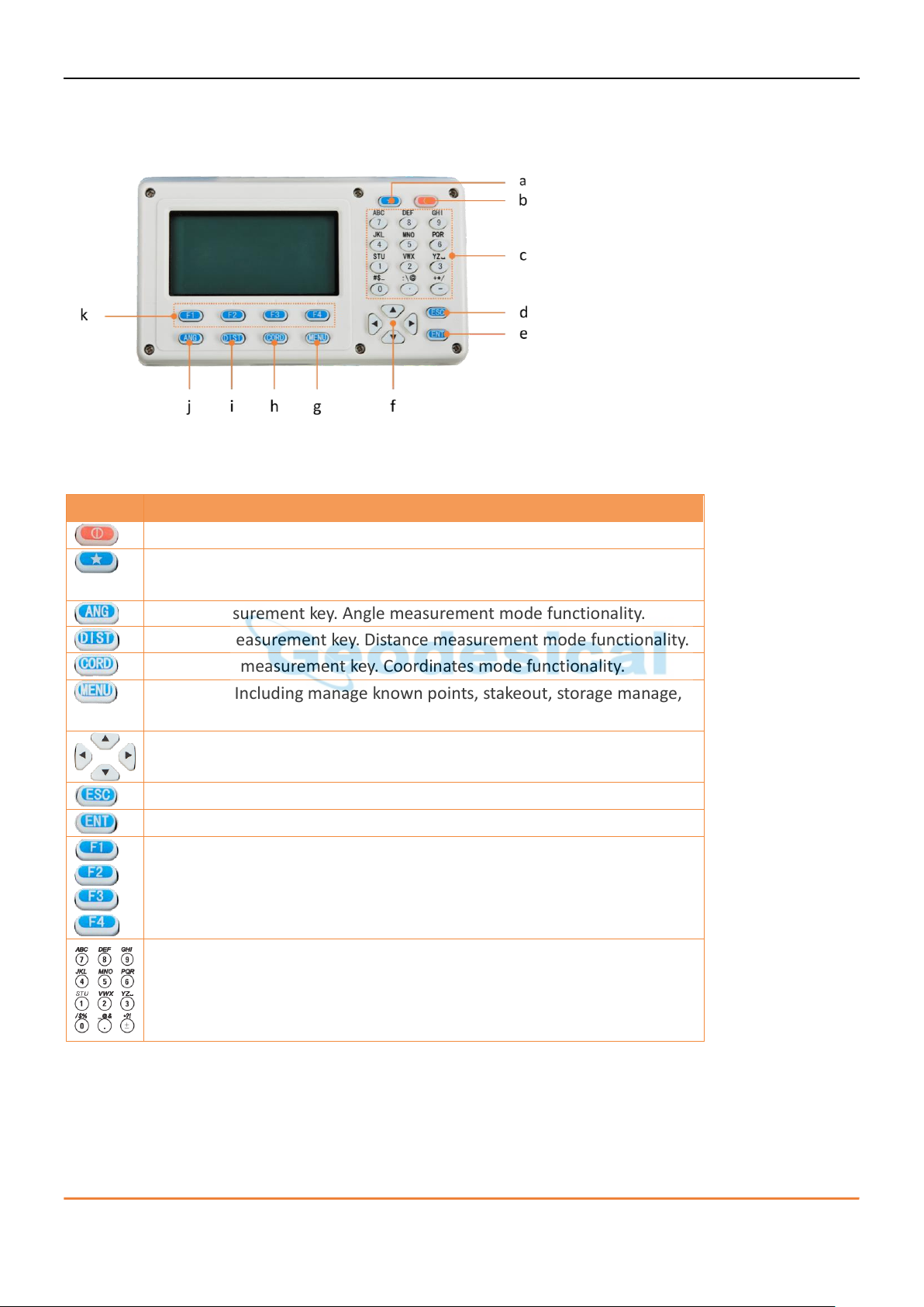
a) Star function button
b) On/Off key
c) Alphanumeric keypad
d) ESC key
e) ENTER key
f) Navigation keys
g) Menu key
h) Coordinate measurement key
i) Distance measurement key
j) Angle measurement key
k) Function keys F1 to F4
Device
Description
On / Off button. Switches the instrument on or off.
Star function button. Choose reflector type, plummet intensity,
crosshair and display illumination.
Angle measurement key. Angle measurement mode functionality.
Distance measurement key. Distance measurement mode functionality.
Coordinate measurement key. Coordinates mode functionality.
Menu key. Including manage known points, stakeout, storage manage,
device version and settings.
Navigation keys.
Esc key. Exit from the current interface.
Enter key. Confirms an entry and continues to the next field.
Function keys that are assigned the variable functions displayed at the
bottom of the screen.
Alphanumeric keypad for entry of text and numerical values.
4.2. Keyboard description
When total station power on, it will show angel measurement mode screen (three-page menu).
Keys
CHC CTS-112R4 user manual 9

Symbol
Description
V%:
vertical angle (slope)
HR:
horizontal angle(right)
HL:
horizontal angle(left)
HD:
horizontal distance
VD:
vertical distance
SD:
slop distance
N:
coordinate N
E:
coordinate E
Z:
coordinate Z
*:
EDM (electronic distance meter) is under operation.
m:
meter as the unit
ft:
foot as the unit
fi:
foot and inch as the unit
Displayed symbols
CHC CTS-112R4 user manual 10
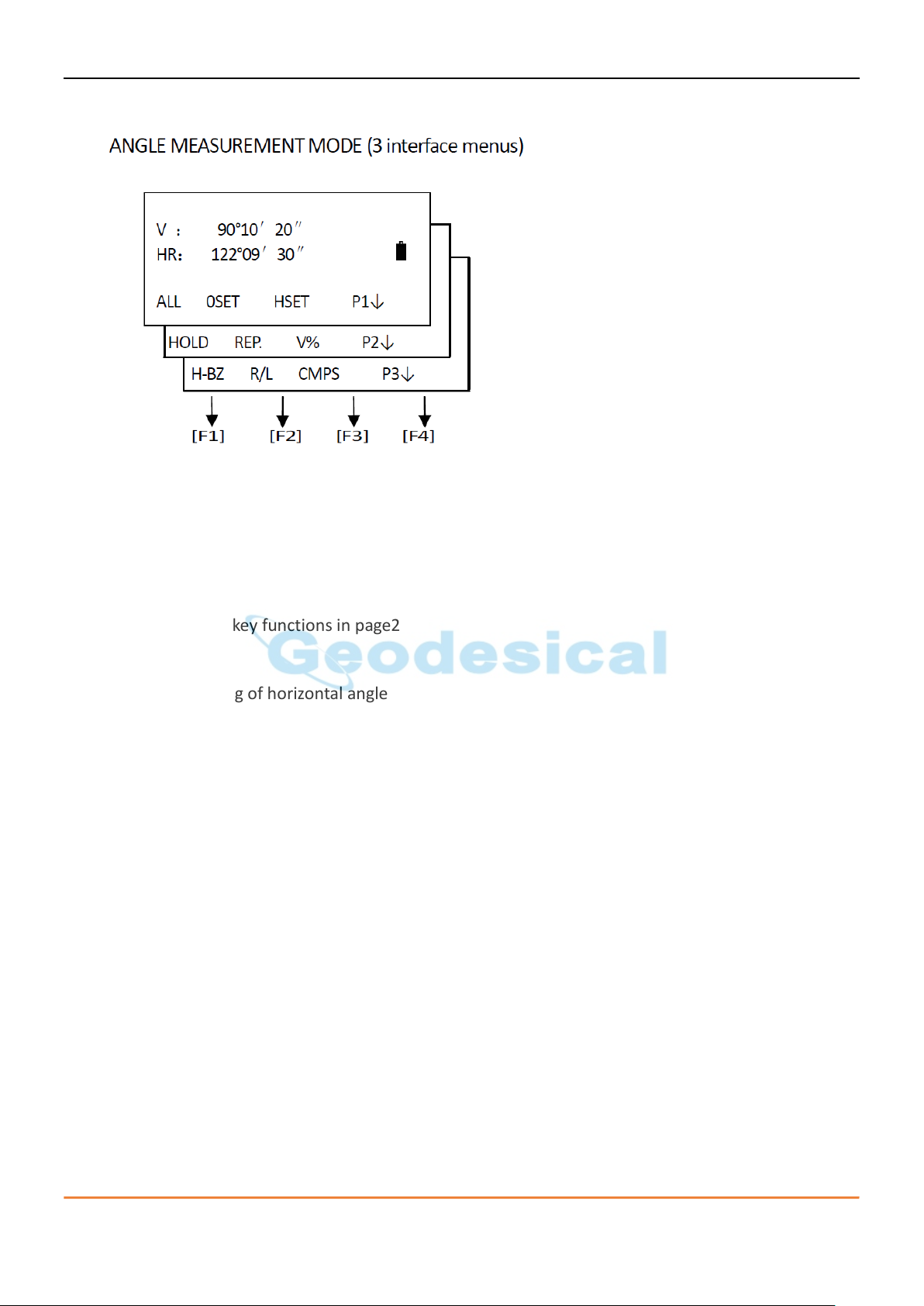
4.3. Functional keys
Page1
ALL: Start angle measurement and save the results in respective job. (Measurement files and coordinates
files are selected in DATA COLLECT menu.)
0SET: Set horizontal angle to 0 degree
HSET: Input a horizontal angle by keyboard
P1↓: Display the soft key functions in page2
Page2
HOLD: Lock the reading of horizontal angle
REP.: Repeat measuring on horizontal angle
V%: Shift between vertical angle/slope percentage
P2↓: Display the soft key functions on page3
Page3
H-BZ: Set ON/OFF for the beep when the horizontal angle reaches 0°, 90°, 180°, 270°
R/L: Shift between right/left angle of horizontal angle
CMPS: Shift the display format of vertical angle (vertical angle/azimuth angle)
P3↓: Display the soft key functions on page1
CHC CTS-112R4 user manual 11
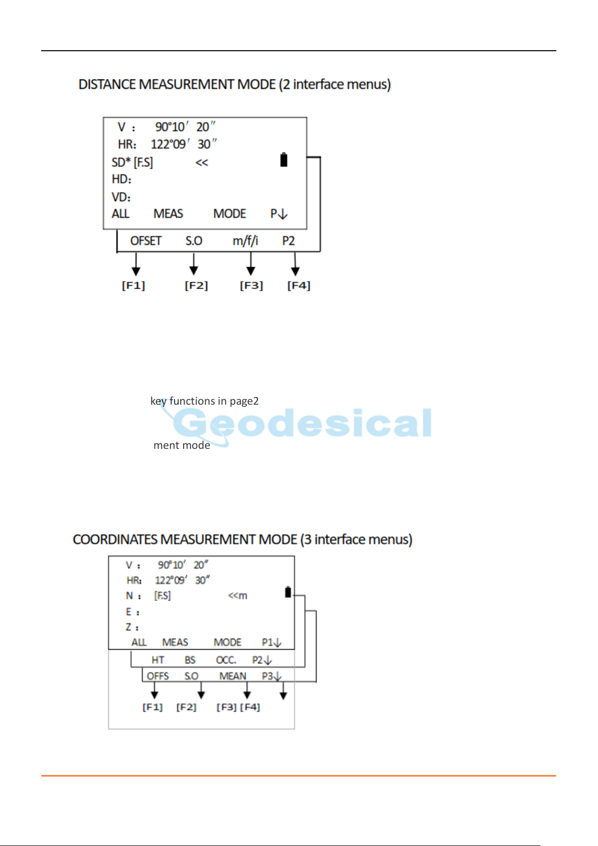
Page1
ALL: Start distance measurement and save the results in respective job. (Measurement files and
coordinates files are selected in DATA COLLECT menu.)
MEAS: Start distance measurement
MODE: Shift the distance measurement modes (F.S/F.N/F.R/T.R)
P1↓: Display the soft key functions in page2
Page2
OFSET: Offset measurement mode
S.O: Distance stake out mode
m/f/i: Set distance unit (meter/feet/feet. inch)
P2↓: Display the soft key functions in page1
CHC CTS-112R4 user manual 12
Page1
ALL: Start coordinates measurement and save the results in respective job. (Measurement files
and coordinates files are selected in DATA COLLECT menu.)
MEAS: Start coordinates measurement
MODE: Shift the distance measurement modes (F.S/F.N/F.R/T.R)
P1↓: Display the soft key functions in page2
Page2
HT: Set the instrument height and target height
BS: Set the coordinates of the backsight point
OCC.: Set the coordinates of the occupied point
P2↓: Display the soft key functions in page3
Page3
OFFS: Offset measurement mode
S.O: Coordinates stake out mode
MEAN: Set the measuring time of fine measurement
P3↓: Display the soft key functions in page1
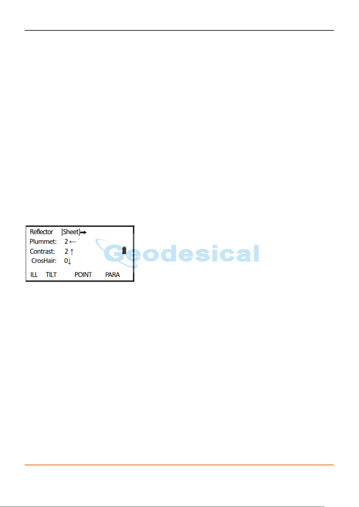
4.4. Star (★) key mode
Press ★, the screen will show:
Press Star key [★], you can set the below items:
1) Contrast: Press [↓] , you can adjust the contrast of the LCD.
2) Illumination:
Press [F1]: turn on the background light
Press [F1] again: turn off the background light
3) Tilt Compensation: press [F2] to enter to settings of tilt compensation. Press [F1] or [F3] to switch tilt
sensor ON/OFF.
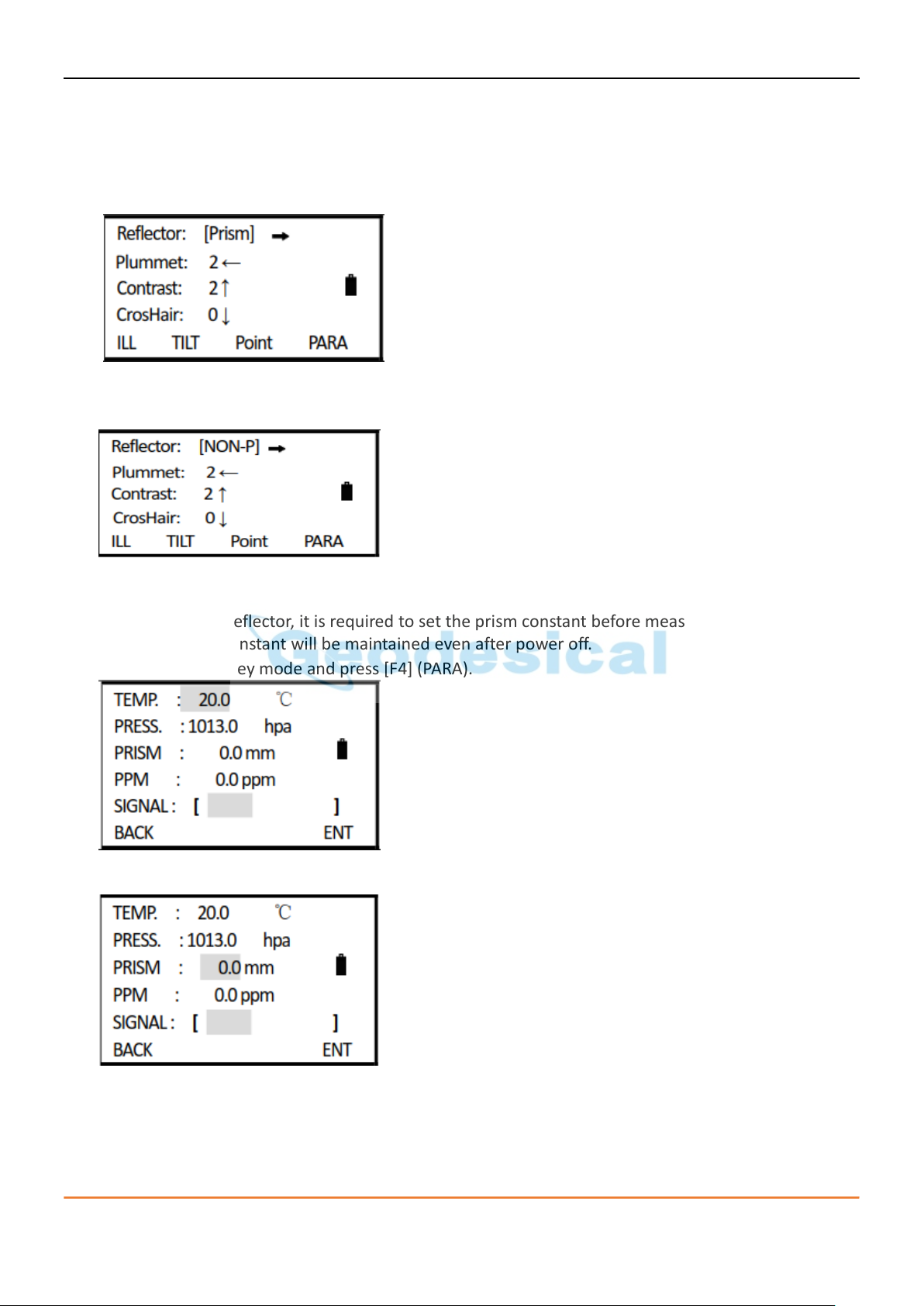
4) Reflector: Press [★] to set the reflector type. Press [→] every time to shift the reflector type among
Prism/NON-P/Sheet.
5) Pointer: Press [F3] to activate the visible laser beam.
6) Parameter: Press [F4] to select “PARA”, you can set the prism constant, PPM value, temperature and
atmospheric pressure and check the reflecting signal.
CHC CTS-112R4 user manual 13

5. Description of the instrument
5.1. Power On/Off
1) Turn on the power, the screen will show:
2) Insert a SD card, the instrument will start to detect the SD card.
3) After inspection, you can enter to measurement mode automatically.
Hold [POWER] for 3 seconds to switch off the power.
5.2. Setting of tilt correction on vertical and horizontal angles
When activating the tilt sensor, it will show the correction value of vertical and horizontal angles because
the instrument is not perfectly leveled. To ensure the measurement accuracy, the tilt sensor should be
activated (single/dual axis), which will facilitate you to level the instrument better. When the tilt sensor
interface appears, it needs to be leveled manually.
• The CTS-112R series can automatically correct the horizontal and vertical angle readings deviations
which are caused by tilt of instrument’s vertical axis on X and Y direction.
• The CTS-112R series provide 3 tilt correction modes: disable tilt sensor, X-ON (single axis) and XYON
(dual axis). Dual axis compensation: correct the errors of horizontal angle caused by the index error
of vertical angle and tilt of vertical axis. When it exceeds the limit, the tilt sensor interface will
appear. User should level the instrument manually. Single axis compensation: correct the index error
of vertical angle. When it exceeds the correction limit of vertical angle, the tilt sensor interface will
appear.
• Disable tilt sensor: close the tilt compensator.
If the instrument operates under an unstable status or windy days, the vertical angle displays unstably. In
such circumstances, the tilt sensor should be disabled, so that it will avoid the instrument from
displaying error messages as well as abortion of measurement caused by the tilt sensor exceeding the
correction limit.
CHC CTS-112R4 user manual 14
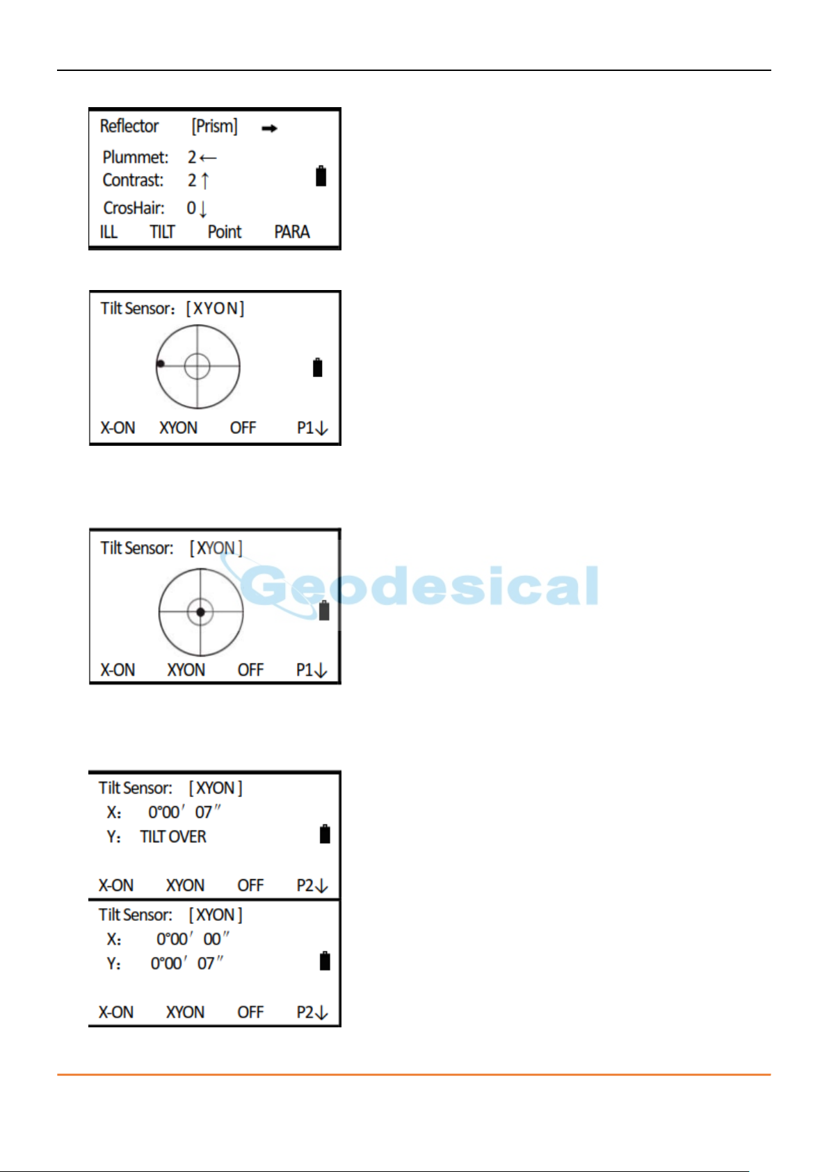
1) Enter Star (★) key mode.
2) Press [F2] to enter to tilt correction settings.
3) When the tilt of instrument exceeds the correction range, it needs leveling manually. Follow the
steps described in “Instrument Setup” to center the black dot, as shown on the right.
Single Axis: only corrects the vertical angle. Dual Axis: corrects vertical and horizontal angles.
4) Press [F4] (↓) to display the tilt value on X (horizontal) and Y (vertical) direction. It needs leveling
manually. Rotate the screws on the tribrach to level the instrument. Press [ESC], return to Star key
mode. Press [F3] to disable the correction.
5) If the tilt sensor is disabled, press [F1] (X-ON) or [F2] (XYON) to activate the correction function.
CHC CTS-112R4 user manual 15
5.3. Setting distance measurement mode
Total station CTS-112R series can adopt visible laser distance measurement and invisible IR distance
measurement. Prism, NON-prism and reflecting sheet are selectable as reflector. User can set a mode
according to the job requirement.
1) Enter Star (★) key mode.
2) Press [MENU] to select the type of reflector. Press [MENU] every time to shift among Prism/ NON-P
sheet. Press [ESC] to save the settings and return to measurement mode.
5.4. Setting of tilt correction on vertical and horizontal angles
When using prism as reflector, it is required to set the prism constant before measurement. As the prism
constant is set, such constant will be maintained even after power off.
1) Enter to Star (★) key mode and press [F4] (PARA).
2) Press [▼] to move down to prism constant item.
CHC CTS-112R4 user manual 16
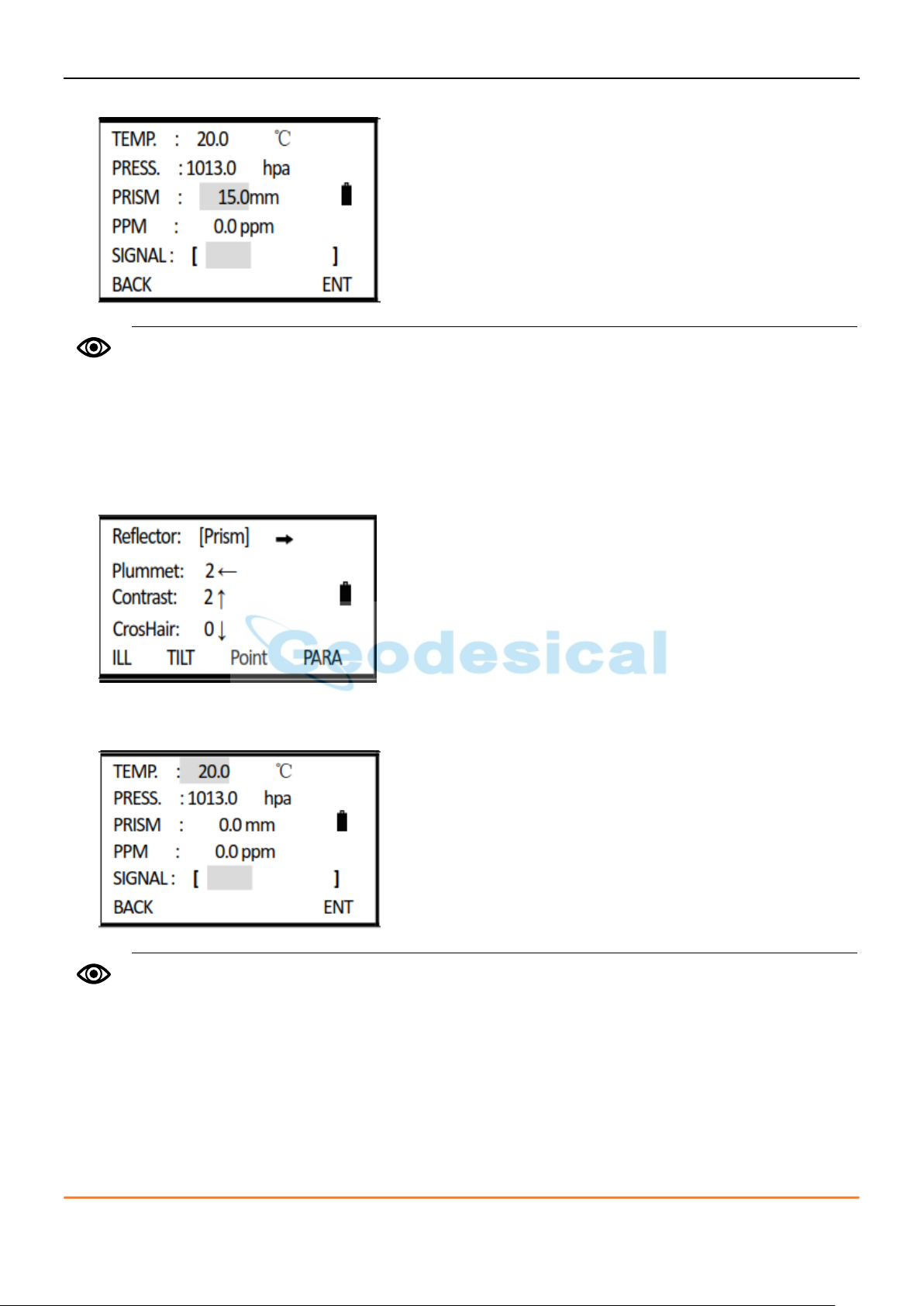
Refer to section 6.7 “Method of inputting, alphanumeric characters” to learn how to input
numbers or characters. Inputting range: -99.9 mm to +99.9 mm Step length: 0.1 mm.
When receiving the reflecting light, the instrument will buzz. To disable the buzzer, refer to
section 13 “Parameters”.
3) Input prism constant correction vale and press [F4] (ENT). Press [ESC] to return to Star key mode.
5.5. Reflecting signal
Reflecting signal function displays the intensity of EDM’s reflecting signal. It helps user to collimate the
target in tough conditions. In circumstance that target is not easy to be found, this function will help you
easily collimate the target.
1) Enter Star (★) key mode.
2) Press [F4] (PARA) to display the intensity (signal) of the reflecting light. It will show the intensity by a
column.
3) Press [ESC] to return to Star key mode.
CHC CTS-112R4 user manual 17

When the unit of atmospheric pressure is mmHg, follow this formula: 1 hPa = 0.75 mmHg
5.6. Setting atmospheric correction
When during distance measurement, the result may be affected by atmospheric condition. To overcome
the affection of the atmospheric condition, it is necessary to use make correction through atmospheric
correction constant during distance measurement.
• Temperature: the temperature of the surrounding air.
• Pressure: the atmospheric pressure surrounding the instrument.
• PPM: the atmospheric correction calculated and estimated.
Standard atmospheric condition of total station CTS-112R series (i.e. the atmospheric condition when
the atmospheric correction value is 0):
• Pressure: 1013hPa
• Temperature: 20°C
In the formula:
• Correction coefficient (unit: ppm)
• P: pressure (unit: hpa)
• T: temperature (unit: °C)
5.6.1. Setting the atmospheric correction value directly
Measure the temperature and press, then calculate the atmospheric correction value (PPM) through the
atmospheric correction graph or the formula.
1) Enter Star (★) key mode, press [F4] (PARA).
2) Press [▼] to move down to PPM item.
CHC CTS-112R4 user manual 18
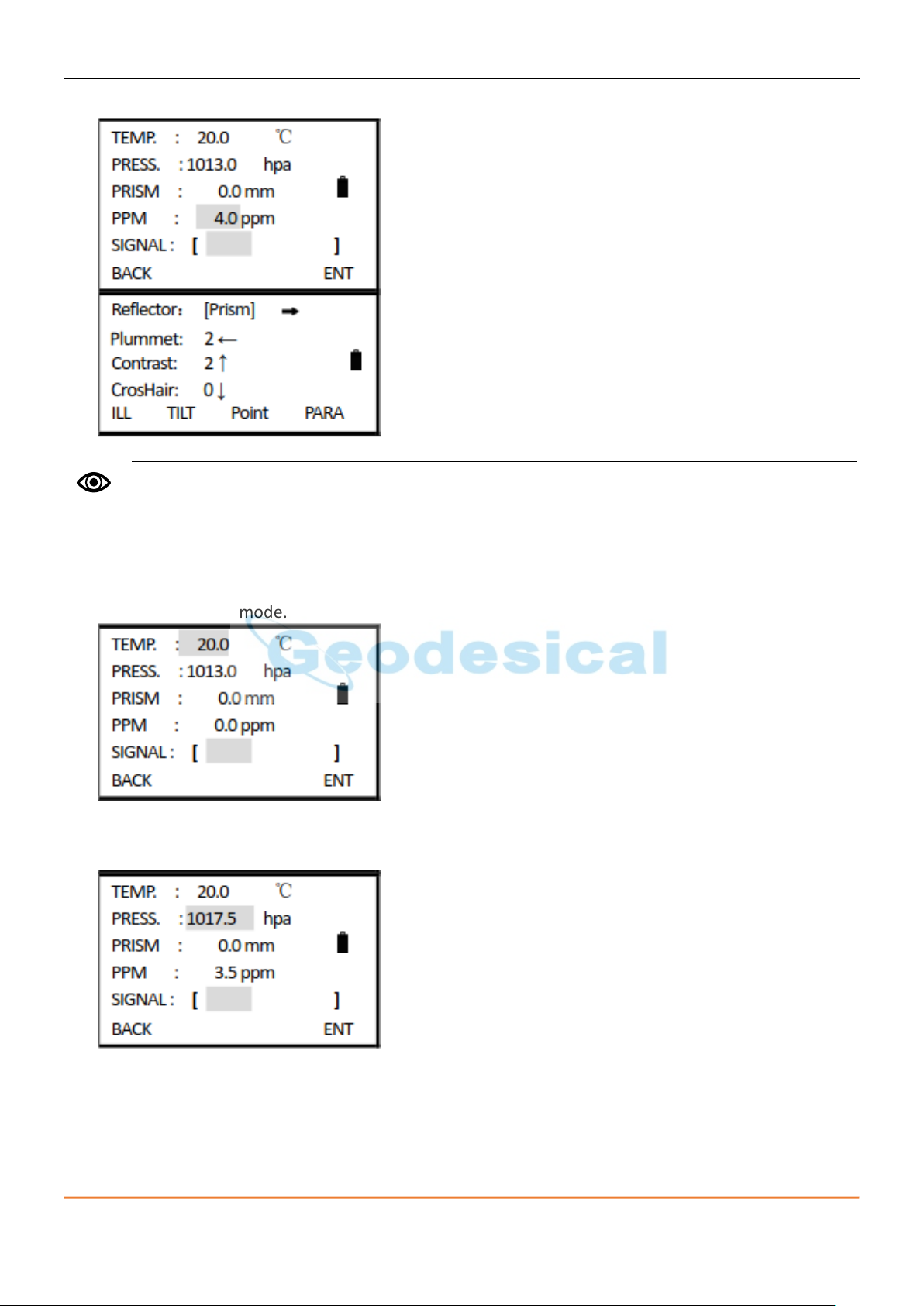
Refer to 6.7 “Method of inputting, alphanumeric characters” to learn how to input numbers
or characters. Inputting range: -99.9 mm to +99.9 mm Step length: 0.1 mm.
3) Input the atmospheric correction value, and press [F4] (ENT) to return to Star key mode.
5.6.2. Calculating the atmospheric correction based on temperature and pressure
Measure the temperature and pressure of the surrounding air previously. E.g. temperature: +25°C,
pressure: 1017.5 hPa
1) Enter Star (★) key mode.
2) Press [F4] (PARA) to enter to parameter settings. Input the temperature and pressure values, the
system will calculate the PPM value automatically according to the values you input.
CHC CTS-112R4 user manual 19
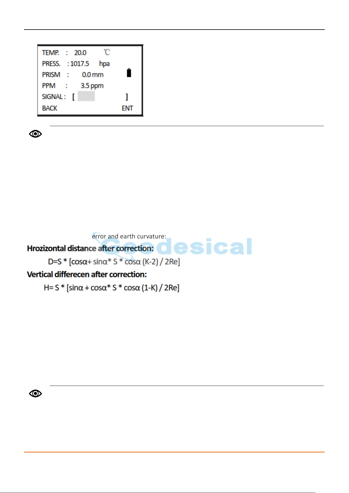
Refer to 6.7 “Method of inputting, alphanumeric characters” to learn how to input numbers
or characters.
Inputting range of temperature: -30° +60°C (step: 0.1°C) or -22 +140℉ (step: 0.1℉)
Inputting range of pressure: 560-1066 hPa (step: 0.1 hPa) or 420~800 mmHg
(step length: 0.1 mmHg) or 16.5-31.5 inHg (step: 0.1 inHg)
The default value of the atmospheric refraction is set to K = 0.14. K can be set to 0.14 or 0.2. It
can also be closed. To modify the K value, refer to section 13 “Parameters”.
3) Press [F4] (ENT) to return to Star key mode.
If the PPM calculated according to temperature and press input is beyond ±999.9 ppm, the system will
return to Step 2 automatically and you should input the value again.
5.7. Correction on atmospheric refraction error and earth curvature
During horizontal distance measurement and height difference measurement, the instrument corrects
the atmospheric refraction error and earth curvature automatically. Formula of correction on
atmospheric refraction error and earth curvature:
If you do not correct the atmospheric refraction error and earth curvature, the formula for HD and VD:
• D = S∙cosα
• H = S∙sinα
In the formula:
• K = 0.14 - coefficient of atmospheric refraction
• Re = 6370 km - radius of earth curvature
• α (or β) - vertical angle measured from horizontal plane (vertical angle)
• S - slide distance
5.8. Setting minimum reading of setting angle/distance
Setting of minimum reading, the units of angle/distance measurement are selectable.
Angle unit : 1”/ 5”/ 10”/ 0.1”
Distance Unit: 1 mm/ 0.1 mm
CHC CTS-112R4 user manual 20
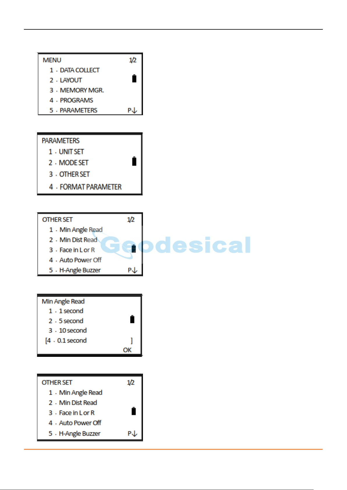
[E.g.] Minimum Reading: 0.1”
1) Press [MENU] to enter to 1/2 of main menu, and press [5] (PARAMETERS).
2) Press [3] (OTHER SET).
3) Press [1] (Min Angle Read).
4) Press [1]~[4] to set the minimum angle reading. e.g.: Press [4] (0.1 second) and press [F4] (OK).
5) Return to menu of OTHER SET.
CHC CTS-112R4 user manual 21

5.9. Setting auto power OFF
When no key is pressed, or no survey is implemented in 30 minutes, the instrument will be switched off
automatically.
1) Press [MENU] to enter to 1/2 of the main menu, and press [5] (PARAMETERS).
2) Press [3] (OTHGER SET).
3) Press [4] (Auto Power Off).
4) Press [1] (OFF) or [2] (ON), and press [F4] (OK).
5) Return to menu of OTHER SET.
CHC CTS-112R4 user manual 22
Refer to 6.7 “Method of inputting, alphanumeric characters” to learn how to input numbers
or characters.
The instrument constant is strictly preset before release. Users are not recommended to
modify such settings in normal use, unless user has implemented a precise measure (e.g.
measurement made by professional inspection organization in a standard baseline field) and
needs to modify the default settings.
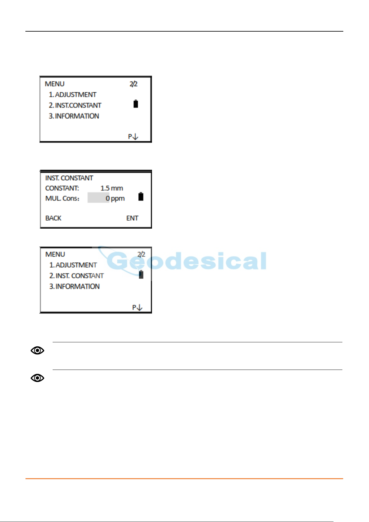
5.10. Setting instrument constant
Follow the method described in section 15.9 “Instrument constant (K)” to calculate the addictive
constant of the instrument. Setting of instrument constant is stated below.
1) Press [MENU] to enter to the main menu, and press [F4] (P↓) to turn to 2/2, then press [2].
2) It displays the instrument constants and multiplication constant. Input the instrument constant and
press [F4] (ENT).
3) Return to 2/2 of the menu.2/2.
4) Press [ESC] to cancel the settings.
CHC CTS-112R4 user manual 23
Refer to 6.7 “Method of inputting, alphanumeric characters” to learn how to input numbers
or characters.
Refer to section 14 “Memory management” to know more about the instruction of disk list and
operation.
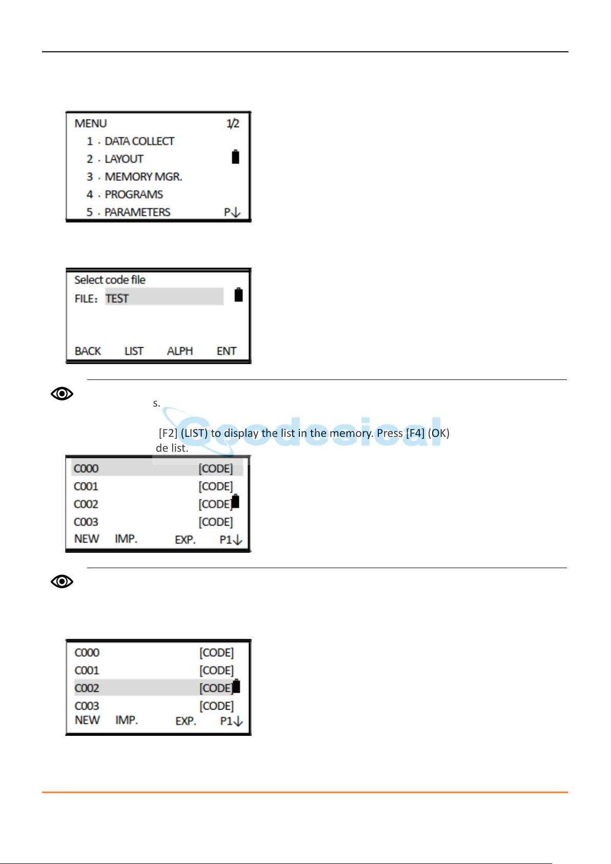
5.11. Select a code file
1) Press [MENU] to enter to the main menu, press [3] into MEMORY MGR, press [4] into SELECT CODE
FILE.
2) When it displays the interface of selecting a code file, enter the file name of the code you want to
call up.
3) You can also press [F2] (LIST) to display the list in the memory. Press [F4] (OK) or [ENT] to enter to it
and display the code list.
4) Press [▲] or [▼] to move up or down to select a code file. Press [F4] to turn the page.
5) Press [ENT] (ENT). Succeed to call up a file. Back to MENU interface.
CHC CTS-112R4 user manual 24
6. Preparation for measurements
6.1. Unpacking and storage of instrument
Unpacking of instrument
Place the case lightly with the cover upward, and unlock the case, take out the instrument.
Storage of instrument
Cover the telescope cap, place the instrument into the case with the vertical clamp screw and circular
vial upwards (Objective lens towards tribrach), and slightly tighten the vertical clamp screw and lock the
case.
6.2. Instrument setup
Mount the instrument to the tripod. Level and center the instrument precisely to ensure the best
performance.
6.2.1. Leveling and Centering the Instrument by plumb bob
1) Set up the tripod.
2) First, extend the extension legs to suitable length, make the tripod head parallel to the ground and
tighten the screws.
3) Make the center of the tripod and the occupied point approximately on the same plumb line.
4) Step on the tripod to make sure if it is well stationed on the ground.
5) Attaching the instrument on the tripod.
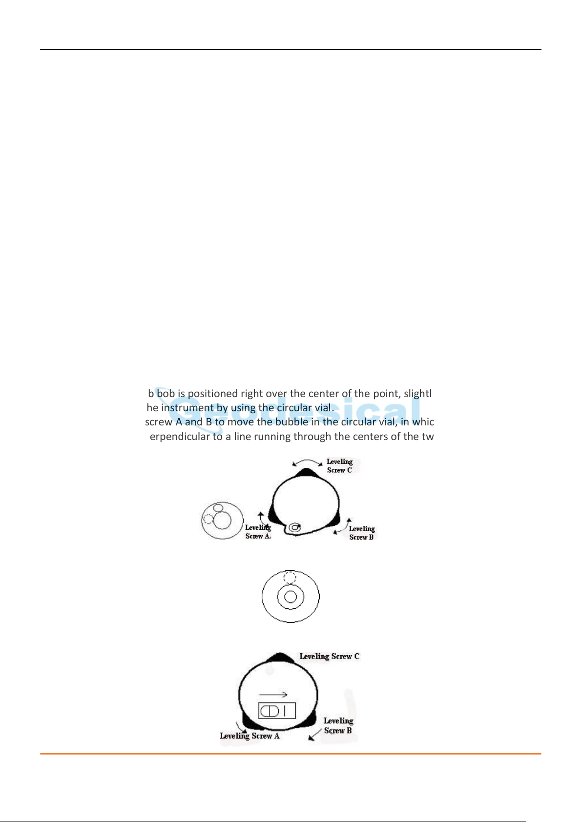
6) Place the instrument carefully on the tripod head and slide the instrument by loosening the tripod
screw. If the plumb bob is positioned right over the center of the point, slightly tighten the tripod.
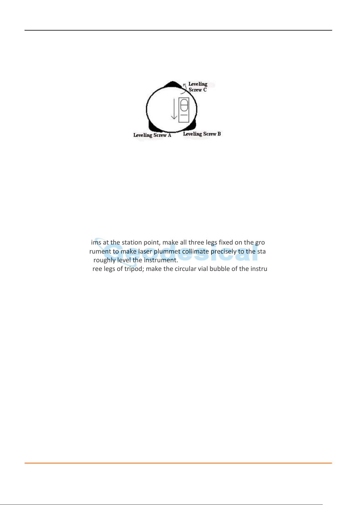
7) Roughly leveling the instrument by using the circular vial.
8) Turn the leveling screw A and B to move the bubble in the circular vial, in which case the bubble is
located on a line perpendicular to a line running through the centers of the two leveling screw being
adjusted .
9) Turn the leveling screw C to move the bubble to the center of the circular vial.
10) Precisely leveling by using the plate vial.
CHC CTS-112R4 user manual 25
11) Rotate the instrument horizontally by loosening the horizontal clamp screw and place the plate vial
parallel to the line connecting leveling screw A and B, and then bring the bubble to the center of the
plate vial by turning the leveling screws A and B.
12) Rotate the instrument 90º(100g) around its vertical axis and turn the remaining leveling screw or
leveling C to center the bubble once more.
13) Repeat the steps 1 and 2 for each 90° (100 gon) rotation of the instrument and check whether the
bubble is correctly centered in all directions.
6.2.2. Centering by using the laser plummet
1) Set up the tripod.
2) Lift tripod to suitable height, ensure equal length of three legs, spread and make tripod head
parallel to the ground, and place it right above the measurement station point. Prop up tripod on
the ground and fix one leg.
3) Install instrument and collimate the point
4) Set instrument carefully on tripod, tighten the central connecting screw. Hold the other two unfixed
legs with both hands and adjust position of these two legs through observation of laser plummet. As
it approximately aims at the station point, make all three legs fixed on the ground. Adjust three leg
screws of the instrument to make laser plummet collimate precisely to the station point.
5) Use circular vial to roughly level the instrument.
6) Adjust length of three legs of tripod; make the circular vial bubble of the instrument in the middle.
7) Use plate vial to level the instrument accurately.
8) Rotate the instrument horizontally by loosening the Horizontal Clamp Screw and place the plate vial
parallel to the line connecting leveling screw A and B, and then bring the bubble to the center of the
plate vial by turning the leveling screws A and B.
9) Rotate the instrument 90℃, make it perpendicular to the connecting line of level screws A and B.
Turn level screw C to make the bubble of the plate vial in the middle.
10) Precisely centering and leveling.
11) Through observation of laser plummet, slightly loosen the central connecting screw and move the
instrument evenly (Don’t rotate the instrument), making the instrument precisely collimating to the
station point. Then tighten the central connecting screw and level the instrument precisely again.
12) Repeat this operation till the instrument collimate precisely to the measurement station point.
CHC CTS-112R4 user manual 26
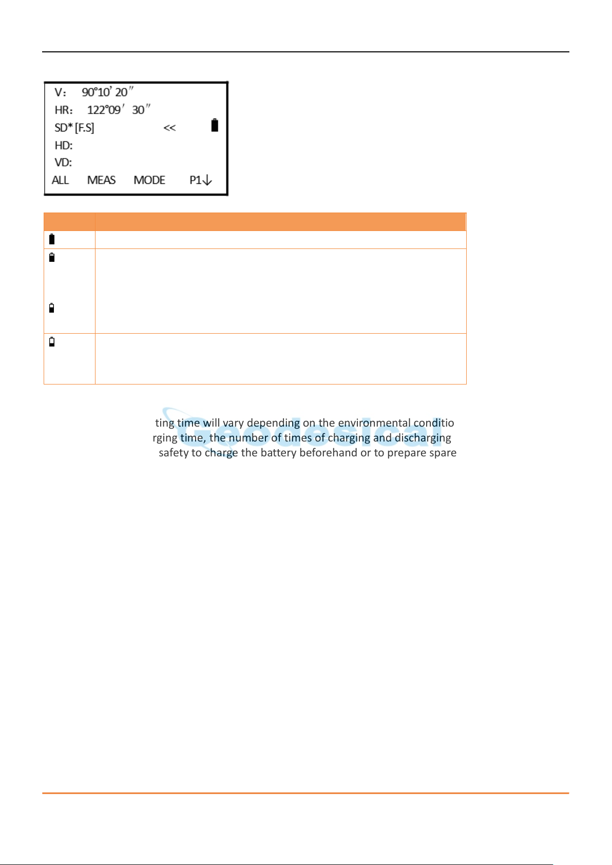
Symbol
Description
Battery is full, good for operation)
When displaying this status, the battery can be used for an hour; if you
are not sure the time it has used, please prepare a substitutional
battery or charge the battery
The battery is low. Please abort the job and change or charge the
battery
Twinkles and disappears. It will just take several minutes when the
symbol twinkles and finally disappears. The battery is empty and please
change and charge the battery
6.3. Loading, unloading, charging the battery and its information
Notice:
• The battery operating time will vary depending on the environmental conditions such as ambient
temperature, charging time, the number of times of charging and discharging etc. It is
recommended for safety to charge the battery beforehand or to prepare spare full charged
batteries.
• The battery power remaining display shows the power level regarding the current measurement
mode. The distance measurement mode consumes more power than angle measurement mode, so
the power enough for the latter is not sure applicable for the previous one. Pay attention to this
when switching angle measurement mode to distance measurement mode, because insufficient
battery power might lead to interrupted operation.
Cautions for unloading the battery:
When unloading the battery, please switch off the instrument in case the instrument may be damaged.
Charging the battery
Charge the battery with the appropriative charger (LC-01). Before charging, link the charger with the
electrical outlet first. Unload the battery from the instrument and connect the charger plug with the
charging outlet of the battery. When the indicator light of the charger is red, it means the battery is
being charged. When the light is green, it means the battery is charged and full, please pull out the plug.
Cautions for charging
• The charger has built-in circuitry for protection from overcharging. However, do not leave the
charger plugged into the power outlet after recharging is completed.
• Be sure to recharge the battery at a temperature of 0°~±45°C, recharging may be abnormal beyond
the specified temperature range .
CHC CTS-112R4 user manual 27
• When the indicator lamp does not light after connecting the battery and charger, either the battery
or the charger may be damaged. Please connect professionals for repairing.
Cautions for storage:
• Rechargeable battery can be repeatedly recharged 300 to 500 times. Complete discharge of the
battery may shorten its service life.
• To get the maximum battery life, be sure to recharge it at least once a month.
6.4. Reflecting prism
When measuring distance, a reflector prism needs to be placed at the target place. Reflector systems
come with single prism and triple prisms, which can be mounted with tribrach onto a tripod or mounted
onto a prism pole. Reflector systems can be self-configured by users according to job.
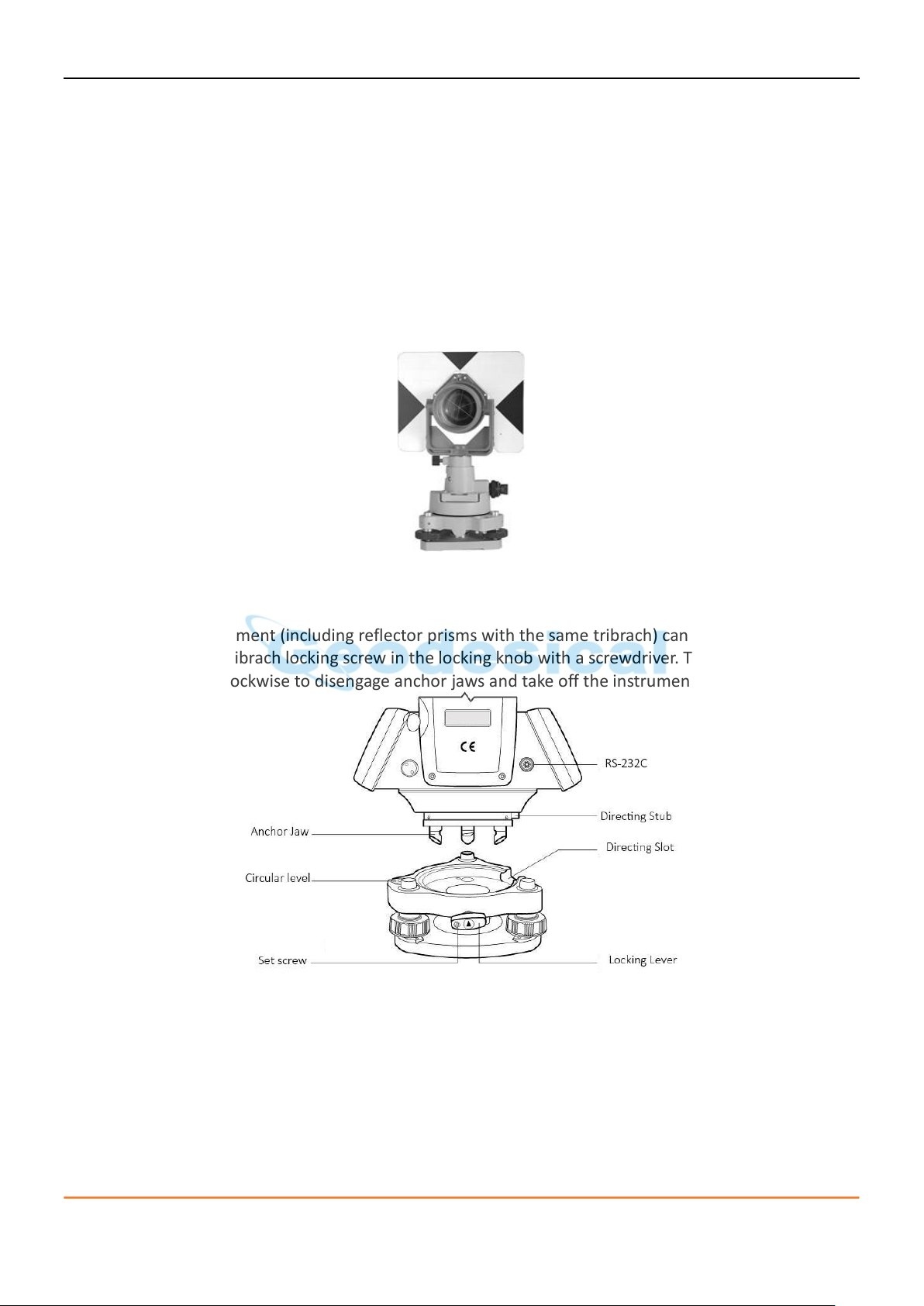
6.5. Mounting and dismounting instrument from tribrach
Dismounting
If necessary, the instrument (including reflector prisms with the same tribrach) can be dismounted from
tribrach. Loosen the tribrach locking screw in the locking knob with a screwdriver. Turn the locking knob
about 180° counter-clockwise to disengage anchor jaws and take off the instrument from tribrach.
Mounting
Insert three anchor jaws into holes in tribrach and line up the directing stub with the directing slot. Turn
the locking knob about 180°clockwise and tighten the locking screw with a screwdriver.
CHC CTS-112R4 user manual 28
If there is parallax when your eye moves up, down or left, right, it means the diopter of
eyepiece lens or focus is not well adjusted and accuracy will be influenced, so you should
adjust the eyepiece tube carefully to eliminate the parallax.
6.6. Eyepiece adjustment and collimating object
Method of collimating object (for reference)
1) Sight the telescope to bright place and rotate the eyepiece tube to make the reticle clear.
2) Collimate the target point with top of the triangle mark in the coarse collimator. (Keep a certain
distance between eye and the coarse collimator).
3) Make the target image clear with the telescope focusing screw.
6.7. Method of inputting, alphanumeric characters
Total station CTS-112R series is equipped with alphanumeric keyboards. User can input number and
characters during operation.
Inputting numbers
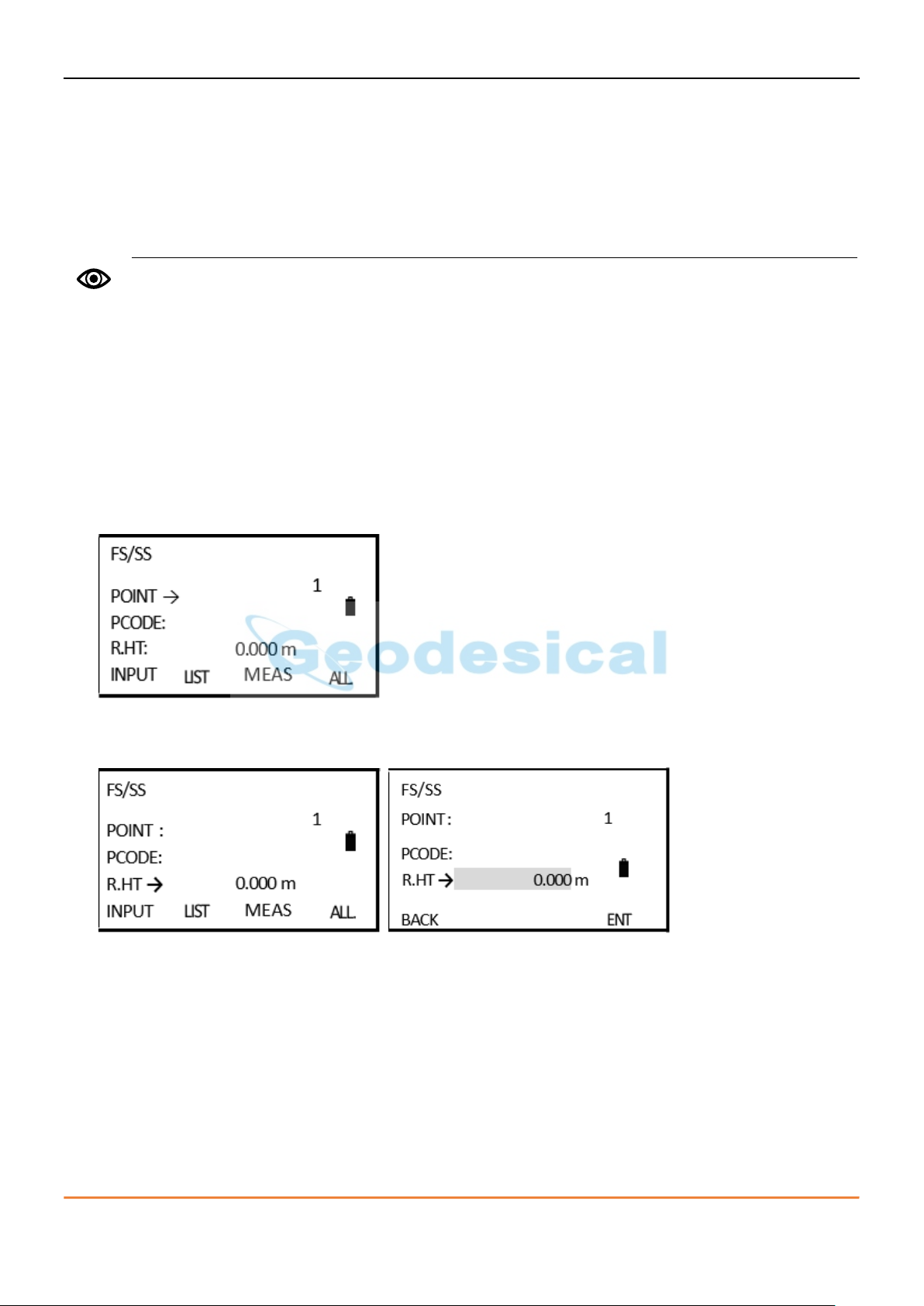
Example1: input the instrument height in data collect mode.
1) The arrowhead points to the item which needs to be input. Press [▲] [▼] to move up or down the
arrowhead.
2) Press [▼] to move the “→” to the item of “R.HT”.
3) Press [F1] (INPUT) to activate the inputting function. The item of reflector height will appear a cursor.
4) Press [1] to input a “1”.
5) Press [.]to input a “. ”.
6) Press [5] to input a “5 ”.
7) After inputting, press [F4] to confirm.
Then the instrument height is defined to 1.5 m.
CHC CTS-112R4 user manual 29

When “ALPH” shows, it means you can type numbers, while “NUM” shows, it means you can
type characters.
Press [F1] (BACK) to delete the characters or numbers you entered.
Inputting angle
Example2: input the angle 90°10′20″.
1) Press [9] to input a “9”; press [0] to input a “0”. Press [.] to input the unit “ ° ”.
2) Press [1] to input a “1”; press [0] to input a“0”. Press [.] to input the unit“ ′”.
3) Press [2] to input a “2”; press [0] to input a “0”. Press [F4] to confirm.
Then the horizontal angle is defined as 90°10′20″.
CHC CTS-112R4 user manual 30
 Loading...