

Page 1

GETTING STARTED GUIDE
X91GNSS
Page 2

Copyright
Copyright 2009-2011 CHC. © 2010-Shanghai HuaCe Navigation Technology Ltd. All rights
reserved. The CHC are trademark of Shanghai Huace Navigation Technology Limited. All
other trademarks are the property of their respective owners- Rev, August, 2010.
Trademarks
All product and brand names mentioned in this publication are trademarks of their
respective holders.
FCC Notice
CHC X91 receivers comply with the limits for a Class B digital device, pursuant to the Part 15
of the FCC rules when it is used in the Portable Mode.
Operation is subject to the following two conditions:
(1) This device may not cause harmful interference and (2) this device must accept any
interference received, including interference that may cause undesired operation.
Replacing Radio Transmitter Power Fuse
Radio transmitter is protected by a 5-A fuse inserted in the power cable. This Y-shaped
cable is used to connect the car battery to the CHC Datalink.
When you have to replace this fuse, please get a spare fuse, 5 A, ATO type, and then do the
following:
Unplug the battery end of the data/power cable
Open the fuse holder located along the data/power cable
Extract the damaged fuse
Insert the new fuse and then push the holder lid back into place
Connect the power cable back to the battery
Where to Find Information
This manual is designed to guide you through the basic X91 procedures. For more
information please contact CHC via email at support@chcnav.com or via Skype at
chc_support.
Page 3
Content
1. INTRODUCTION ..................................................................................................................... 1
1.1 Technical Assistance .................................................................................................... 1
1.2 Your Comments ........................................................................................................... 1
1.3 Safety Information ....................................................................................................... 1
1.3.1 Warning and Cautions ...................................................................................... 1
1.3.2 Regulations and Safety ..................................................................................... 2
1.3.3 Use and Care ..................................................................................................... 2
2. GENERAL INFORMATION ....................................................................................................... 3
2.1 Overview ...................................................................................................................... 3
2.2 Technical Specification ................................................................................................ 3
2.3 Product Basic Supply Accessories ................................................................................ 5
2.4 Product Option Supply Accessories ............................................................................. 8
3. PRODUCT VIEW ................................................................................................................... 10
3.1 Receiver ..................................................................................................................... 10
3.2 Software Installation ................................................................................................. 12
3.3 Batteries and Power .................................................................................................. 13
3.3.1 External Power supply .................................................................................... 14
3.3.2 Internal Battery .............................................................................................. 14
4. Establish connection between controller and Receiver. ..................................................... 16
4.1 Connecting via data Cable ......................................................................................... 16
4.2 Connecting via Bluetooth .......................................................................................... 16
5. CONFIGURATION AND OPERATION ..................................................................................... 19
5.1 Static Configuration ................................................................................................... 19
5.2 Real-Time Kinematic Configuration ........................................................................... 19
5.2.2 Datalink setting ............................................................................................... 21
Appendix A Log Controller on Internet .............................................................................. 25
Appendix B CHC receiver 10 PIN LEMO definition ............................................................. 27
Page 4
Introduction
1. INTRODUCTION
Thank you for choosing CHC X91GNSS receivers.
This Getting Started Guide is designed to help you to rapidly
familiarize yourself with your new equipment. Only a selection of
the many CHC X91 GNSS functions is presented in this guide.
1.1 Technical Assistance
If you have a problem and cannot find the information you need in
the product documentation, contact your local Dealer.
Alternatively, please request technical support using the CHC
Website at (www.chcnav.com ) or CHC technical support email
support@chcnav.com.
1.2 Your Comments
Your feedback about the supporting documentation will help us to
improve the products. Please e-mail your comments to
support@chcnav.com.
1.3 Safety Information
This manual describes CHC X91 GNSS Receivers. Before you use
your receiver, please make sure that you have read and understood
this publication, as well as safety requirements.
1.3.1 Warning and Cautions
An absence of specific alerts does not mean that there are no safety
risks involved.
A Warning or Caution information is intended to minimize the risk of
personal injury and/or damage to the equipment.
1
Page 5
Introduction
WARNING-A Warning alerts you to a likely risk of serious injury to
your person and/or damage to the equipment.
CAUTION- A Caution alerts you to a possible risk of serious injury to
your person and/or damage to the equipment.
1.3.2 Regulations and Safety
The receivers contain integral Bluetooth® wireless technology, and
may also send radio signals through an externally-connected data
communication radio. Regulations regarding the use of the
datalink vary greatly from country to country. In some countries,
the unit can be used without obtaining an end-user license. But in
some countries the administrative permissions are required. For
license information, consult your local dealer. Bluetooth® operates
in license-free bands.
1.3.3 Use and Care
The receiver can withstand the rough treatment that typically occurs
in the field. However, the receiver is high-precision electronic
equipment and should be treated with reasonable care.
2
Page 6
General Information
2. GENERAL INFORMATION
2.1 Overview
The X91 receiver provides the following features:
Centimeter-accuracy, real-time positioning with RTK/OTF
data.
Sub-meter-accuracy, real-time positioning using
pseudo-range corrections.
Automatic OTF initialization while moving
Single Lithium-ion rechargeable battery
Cable-free Bluetooth® communications with the data
controllers
One 10-Pin LEMO port for:
o RTCM 2.X and 3.0 input and output
o CMR input and output
o NMEA0183 output
One TNC radio antenna connector
Internal Memory for data storage
2.2 Technical Specification
GNSS characteristic
220 channels with simultaneously tracked satellite signals :
− GPS: L1C/A,L2C, L2E, L5
− GLONASS: L1C/A, L1P, L2C/A, L2P
− SBAS: WAAS, EGNOS, MSAS
− Galileo: GIOVEA and GIOVEB
− Forthcoming Signals
Real Time Kinematics (RTK)
Horizontal: ± (10mm+1ppm) RMS
Vertical: ± (20mm+1ppm) RMS
Initializing Time: 10S
Initialization Reliability: Typical >99.9%
Static
Horizontal: ± (2.5mm+1ppm) RMS
3
Page 7

General Information
Vertical: ± (5+1ppm) RMS
Baseline Length: ≤300km
Data Format
RTCM2.1, RTCM2.3, RTCM3.0, CMR, RTCA, Input and Output
NMEA0183 outputs, GSOF outputs
Physical Reference
Size (H×D): 80mm×180mm
Weight: 1.25Kg (Battery Included)
Electrical Reference
Power Consumption: 2.6W
Battery Volume: 2400mAh
Battery Life: 9 Hours (Static), 5 Hours (RTK)
1000 Recharges
External Power: 9-18VDC
Environment
Working Temperature: -30 °C — +65 °C
Storage Temperature: -40 °C — +75 °C
Humidity: 100% condensation
Waterproof and Dustproof: IP67, protected from temporary
immersion to depth of 1 meter, floating.
Shock and Vibration: Survive from 2 meters drop onto
concretes
Characteristics
Buttons and Display: 2 buttons/4 LED lights
I/O: RS232, High-speed USB, Bluetooth®
Channel: 220 Channels*
Datalink
Power (UHF): 1W-20W Adjustable
Band Width: 410-430MHz/430-450MHz/450-470MHz
*Channel Configuration:
-GPS: Simultaneous L1 C/A, L2E, L2C, L5
-GLONASS: Simultaneous L1 C/A, L1 P, L2 C/A, L2 P
4
Page 8

General Information
Item
Picture
CHC X91GNSS Receiver Base
Lithium Battery
H.I. Tape
Connector
Base Kit Basic Supply
-SBAS: Simultaneous L1 C/A, L5
-GLOVE-A: Simultaneous L1BOC, E5A, E5B, E5AltBOC
-GLOVE-B: Simultaneous L1 CBOC, E5A, E5B, E5AltBOC
2.3 Product Basic Supply Accessories
The tables below provide an overview of the different items
composing the CHC X91 Base Kit. Basic Supply is the standard
accessories for each kit.
5
Page 9
General Information
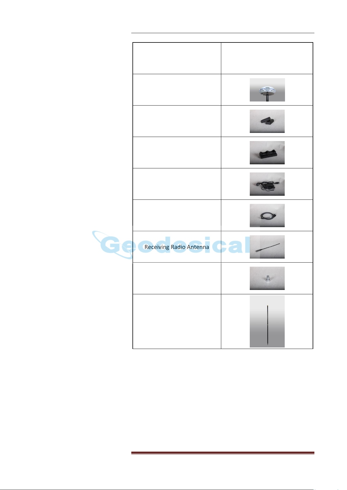
Item
Picture
CHC X91GNSS Receiver Rover
Lithium Battery
Battery Charger
Power Adapter with Cord
GPS to PC Data Cable
Receiving Radio Antenna
Connector
2M Range Pole
Rover Kit Basic Supply
6
Page 10

General Information
Item
Picture
CHC DL3 Datalink
GPS to Datalink Cable
Standard Datalink Antenna with 5
Meter Cable
External Power Cable
Datalink Antenna Mounting Pole
Kit
Pole Mounting
Datalink Kit Basic Supply
7
Page 11

General Information
Item
Picture
LT30 Survey RTK Controller(the
controller is different according
to your order, you may order
Getac or Recon 400)
USB Data Cable of Controller
Battery Charger and Adapter of
Controller
Battery
TF Card
LT30 Controller Kit Basic
Supply
2.4 Product Option Supply Accessories
You may have one of the 4 Handheld Controllers depending on
different requirement and purchase.
8
Page 12

General Information
Item
Picture
Transport Case
Carry Pouch
Metal Transport Case for
Poles and Antenna
Item
Picture
Double Bubbles Tribrach with
High Adapter
Single Bubble Tribrach with
Lower Adapter
External Power Cable
Transportation Cases
Options
Accessories Options
Also there are some more Accessories for your consideration.
Transportation Cases Options and Accessories Options are
depending on different orders requirements.
9
Page 13

Power LED
(RED)
Satellite
LED
Correction
LED
Record LED
(YELLOW)
Power
Button
Switch
(RTK/Static)
3. PRODUCT VIEW
3.1 Receiver
Product View
[X91 Front Panel]
Power Button
To turn on X91GNSS, quick press the power button until the power
LED (red) lights up. After the receiver powers on, the other three
LED will flash together for one time.
Switch Button
The function of switch button is to switch X91GNSS from RTK mode
to static mode. The procedure can be divided into 2 steps.
Step 1: Switching
Long press the button until the Record LED off.
10
Page 14

Product View
Step 2: Checking
Press the switch button, if the correction LED turns on, it means the
switching succeed.
CAUTION: When checking is going on, do not long press, otherwise
RTK mode will be activated.
Power LED (RED)
The indicator to show whether X91GNSS is on or off.
When battery is less than 20%, the power LED will flash
continuously which reminds you to change the battery.
Bluetooth status: after the receiver powers on, if the power LED
(red) flashes quickly for three times in a row, it means the
Satellite LED (BLUE)
The indicator to show the number of satellites that the receiver has
tracked. For example, if the blue LED flashes five times continuously,
it means the receiver has tracked 5 satellites.
Correction LED (GREEN)
The Correction LED only flashes once per second when
A. As a Base station: successfully transmitting differential data in RTK
mode.
B. As a Rover station: successfully receiving differential data from
Base station.
Record LED (YELLOW)
The record LED only flashes under two situations
A. In static mode
The interval of flashing shows the sample interval of collecting data.
B.RTK mode
When the receiver is connecting to Controller and receiving
commands or just communicating with Controller.
[X91 Ports]
RS232 Serial Port
RS232 serial port is a 9 pin 0-shell LEMO connector that supports
RS-232 communications or external power input.
Bluetooth® Port
Bluetooth® port is an integrated port allowing X91GNSS receiver to
communicate with a Bluetooth®-enabled field terminal.
Radio Antenna Connection (only for Rover)
11
Page 15
Product View
It allows you to connect a radio whip antenna to the X91GNSS. There
is only one type of CHC radio antenna connection --- TNC.
Adaptor
The 5/8” adaptor is used for setting up the receiver on the tripod.
Battery Compartment
Please put CHC made battery into the compartment properly
WARNINGS:
Do not store batteries in the receiver unless it is applied.
Do not charge or use the battery if it appears to be damaged or
leaking.
Do not damage the rechargeable Lithium-ion battery. A
damaged battery can cause an explosion or fire, and can result
in personal injury and/or property damage.
Do not expose the battery to fire, high temperature, or direct
sunlight.
Do not immerse the battery in water.
Do not use or store the battery inside a vehicle under hot
weather condition.
Do not drop or puncture the battery.
Do not open the battery or short-circuit its contacts.
GPRS Slot
The slot to insert SIM card, which can provide GPRS wireless net as
data communication channel between base and rover. This method
can be activated only in the areas which are covered by GPRS signals
of local Mobile service company.
3.2 Software Installation
3.2.1 Introduction of Software
HCGPSSet : fieldwork software for the Receiver setup
CAUTION: The setting can work only after the Receiver being turned
off and turned on, and this setting need only to do once if the
setting will not be changed next time.
SurvCE: RTK Surveying software.
12
Page 16
Product View
3.2.2 Installation of the CHC RTK Software
The HCGPSSet software can be copy directly to both PC and the
controller, and also can be used directly.
The SurvCE software is to be installed by synchronous with PC.
First to install Microsoft Activesync into PC if the PC is not Win 7
operation system, the software is available at
http://www.microsoft.com/en-us/download/details.aspx?id=15
Second, connect Controller with PC, run Microsoft Avtivesync,
double click the installation file of SurvCE and follow the
installation procedure.
3.3 Batteries and Power
WARNING-Charge and use the rechargeable Lithium-ion battery
only in strict accordance with the instructions. Charging or using
the battery in unauthorized equipment can cause an explosion or
fire, and can result in personal injury and/or equipment damage.
To prevent injury or damage:
Do not charge or use the battery if it appears to be damaged
or leaking.
Charge the Lithium-ion battery only in a CHC product that is
specified to charge it. Be sure to follow all instructions that
are provided with the battery charger.
Discontinue charging a battery that gives off extreme heat or
a burning odor.
Use the battery only in CHC equipment that is specified to
use it.
Use the battery only for its intended use and according to the
instructions in the product documentation.
WARNING –Do not damage the rechargeable Lithium-ion battery.
A damaged battery can cause an explosion or fire, and can result in
personal injury and/or property damage.
To prevent injury or damage:
Do not use or charge the battery if it appears to be damaged.
Signs of damage include, but are not limited to, discoloration,
warping, and leaking battery fluid.
13
Page 17
Product View
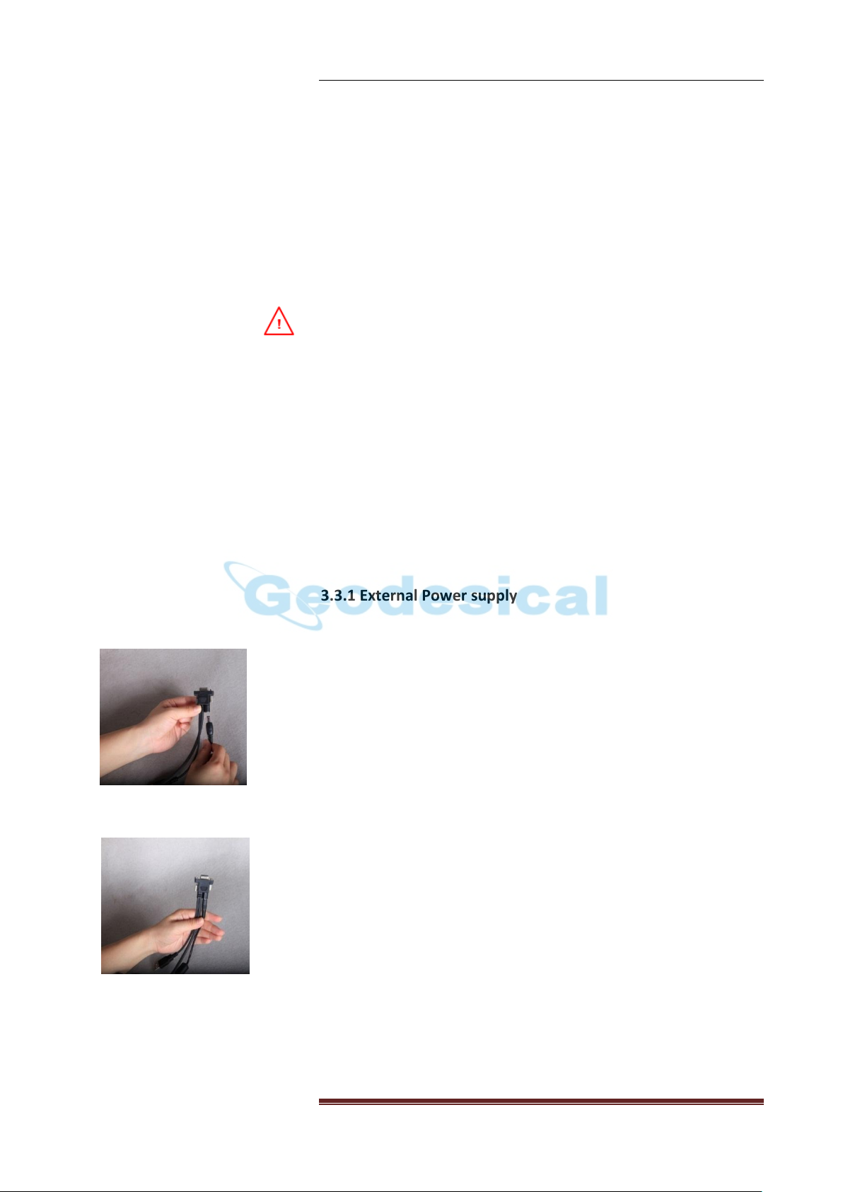
Figure3.3.1-1
Figure3.3.1-2
Figure3.3.1-2
Do not expose the battery to fire, high temperature, or direct
sunlight.
Do not immerse the battery in water.
Do not use or store the battery inside a vehicle under hot
weather condition.
Do not drop or puncture the battery.
Do not open the battery or short-circuit its contacts.
WARNING-Avoid contact with the rechargeable Lithium-ion battery
if it appears to be leaking. Battery fluid is corrosive, and contact
with it can result in personal injury and/or property damage.
To prevent injury or damage:
If the battery leaks, avoid with the battery fluid.
If battery fluid gets into your eyes, immediately rinses your eyes
with clean water and seek medical attention. Please do not rub
your eyes!
If battery fluid gets onto your skin or clothing, immediately use
clean water to wash off the battery fluid.
3.3.1 External Power supply
We have two methods to provide the external power to the receiver
by the CHC GPS to PC cable+ Power Adapter or CHC GPS to PC cable+
external power cable (option purchase)+ car battery.
In the office, the Power Adapter is connecting with AC
power of 100-240V, the output port of the Power Adapter
connects with the Power Port of the GPS to PC cable,
shown as Figure3.3.1-1.
In the field, the external power cable is connecting with
the Car battery, the output port of the external power
cable connects with the Power Port of the GPS to PC cable,
shown as Figure3.3.1-2.
3.3.2 Internal Battery
Two rechargeable lithium-ion batteries are supplied with the
receiver.
● Recommendations for the battery daily use
14
Page 18
Product View
The rechargeable Lithium-ion battery is supplied partially charged.
The following recommendations provide optimal performance and
extend the life of your batteries:
Fully charge all new batteries prior to use.
Do not allow the batteries to discharge below 5 V.
Keep all batteries on continuous charge when not in use.
Batteries may be kept on charge indefinitely without
damage t the receiver or batteries.
Do not store batteries in the receiver or external charger
unless power is applied.
If you must store the batteries, fully charge them before
storing and then recharge them at least every three months.
● Charging the Battery
The battery fully charged will take approximately three hours each
using the charger attached.
Connect the Power Adapter and the charger together.
The red LED in the middle indicates the charger is powered
on.
When the battery is placed in the right place, the
Green/Yellow LED will start to flash or turn on.
The Green/Yellow LED indicates the statement of charging.
When it is flashing, it means the battery is on charging, and
the flashing speed tells the progressing of the battery
charging, in other words, when the battery fully charged, the
Green/Yellow LED will keep lighting but no flashing any
more.
● Battery Disposing Notices
Discharge the lithium-ion battery before dispose of it. When
disposing the battery, be sure to do so in an environmentally
sensitive manner. Adhere to any local and national regulation
concerning battery disposal or recycling.
15
Page 19

Connect To Controller
Figure4.2-1
Tap here to change the
Bluetooth® status
4. Establish connection between controller
and Receiver.
You can connect the receiver with controller using data cable or by
Bluetooth. The CHC RTK software can be installed in Windows® CE
and Windows ® Mobile system Controller. Here the Windows®
Mobile is set as an example to show how to establish connection
with Receiver.
4.1 Connecting via data Cable
Turn on the controller and the GNSS receiver you want to work with.
Connect the controller and the Receiver using GPS to PC cable, the
default Com Port is 1.
Tips: There is a lock in the Lemo, when you touch in the cable,
please use caution. Do touch the metal part of the Lemo not the
plastic part.
4.2 Connecting via Bluetooth
Turn on the controller and the GNSS receivers you want to work
with.
Activate Bluetooth® connection of controller.
Check the Bluetooth® status on the start screen. Turn on the
Bluetooth by tap on the Bluetooth® button, Figure4.2-1. Tap
Done and return to the start screen.
Start Bluetooth Settings
Tap Start ->Settings ->Connections->Bluetooth®. Tap on the
Bluetooth® icon. The Bluetooth® Settings window opens, which
is on the Device tab, Figure4.2-2.
16
Page 20
Connect To Controller
Figure4.2-2
The SN number of Device
Figure4.2-3
Figure4.2-4
Figure4.2-5
Figure4.2-2
Add new device to the list
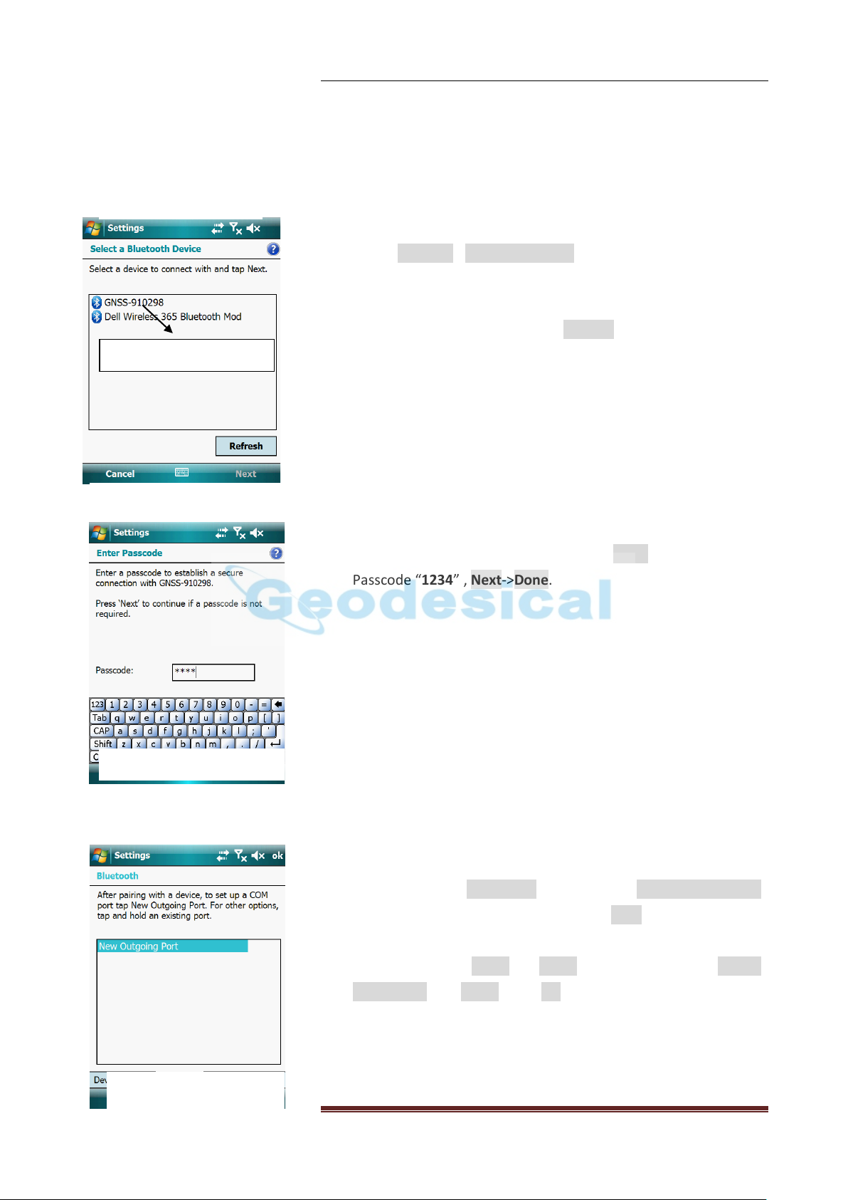
Tap on Devices->Add New device, the PAD start searching for
the Bluetooth® devices nearby. For each device detected by
Controller, the Bluetooth® name is returned in the search
window (e.g.GNSS-400071). The Refresh button can be used to
resume the search if necessary.
Select the Bluetooth® name corresponding to the receiver you
want to communicate with and then tap Next, keying in the
Passcode “1234” , Next->Done.
Establish a Bluetooth Communication
Now come to the COM Ports Tab, select the New Outgoing Port.
Highlight the device name, and then tap Next.
Choose a COM port to connect Bluetooth® with the GNSS
receiver. Choose Com8 or Com9, then unselect the Secure
Connection, tap Finish. Click OK on the top right corner to exit
Bluetooth setting.
17
Page 21
Connect To Controller
Notice: Com8 is suggested to be linked with Base and Com9 with
Rover.
CAUTION: If you want to connect a new receiver to the Controller
using the same Com Port, You should delete the Bluetooth®
connection with GNSS Device which is using the Com Port first in the
COM Ports Tab. Long press the device name, select delete option in
the pop out window.
18
Page 22
Start Surveying Work
5. CONFIGURATION AND OPERATION
5.1 Static Configuration
There are 3 ways to configure the receiver into Static Mode.
A. Using RS232 Port and HcLoader Software in the Office
Connect X91GNSS to your computer through RS232 cable.
Run the software HcLoader and click icon Link to make the
receiver connected with computer.
Click icon Setup to set the sample interval (15S is
recommended) and mask angle of the receiver (13 is
recommended) and choose Data Log mode as Auto, then
click Apply to make the configuration active, click Exit.
Restart the receiver.
B. Using Controller and Software HCGPSSet in the Field
Use RS232 or Bluetooth® port connecting Controller with
receiver.
Tap the icon HCGPSSet on the Controller, choose the right
com port and click Bluetooth® icon if you are using
Bluetooth®.
Click Open, set the sample interval (15S is recommended
and mask angle of the receiver (13 is recommended) you
want and choose the data log mode as Auto, then click
Apply to make the configuration active.
Restart the receiver.
C. Switch Button in the Field
Long press the Switch button until the Record LED off
record LED (the fourth LED) is off.
5.2 Real-Time Kinematic Configuration
To do the RTK, Radio or Ntrip must be chose to be the way to
transmit correction messages, X91 offers both these two ways by
using “CHC Radio + Base Station” or “GPRS Network + CORS”. Now
19
Page 23

Start Surveying Work
Radio
Mode
DCI
(Data
Collector
Internet
) Mode
Rover
we divide these two ways into 3 modes: Radio Mode, GPRS Mode
and DCI mode, and the configurations are shown in the table below:
Table 5.2-1 Configuration for Radio Mode
Radio Mode: install the instruments like the figure in Table 5.2-1
Set up the Base on the Known or Unknown Point.
Set up the Datalink and Antenna Near the Base.
Connect the car battery, the Radio, the Antenna and the
Base with relative cables like the following picture.
CAUTION: The Datalink must be connected in right order, Antenna
first, and then GPS. The most important, power cable the last.
20
Page 24
Start Surveying Work
Figure5.2.2-2
Radio Antenna
Battery (Power
Cable)
Data Cable
Figure5.2.2-2
DCI (Data Collector Internet) Mode:
Insert the SIM card into the SIM card slot on the controller, screw
the rover receiver on the pole, and put the controller adapter in
the right place like the figure in Table 5.2-1.
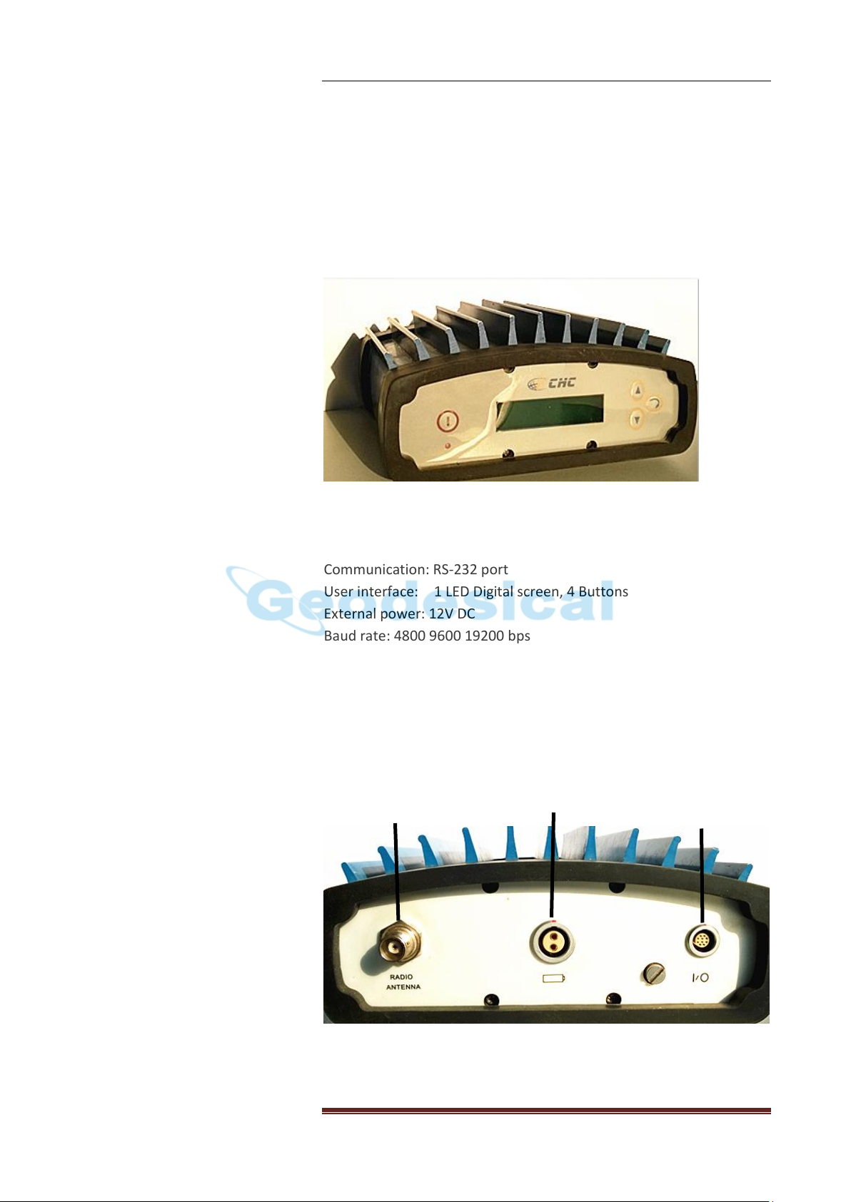
5.2.2 Datalink setting
1. General specification
Dimension: 23.5cmL X 13cmW X 6.5cmH
Weight: 1.9kg
Communication: RS-232 port
User interface: 1 LED Digital screen, 4 Buttons
External power: 12V DC
Baud rate: 4800 9600 19200 bps
Protocol: CHC
Frequency bands: 438-470 MHz
RF Transmitter output: 1-20W
Operating temperature: -40 ℃ -----+65 ℃
2. Connection
21
Page 25
Start Surveying Work
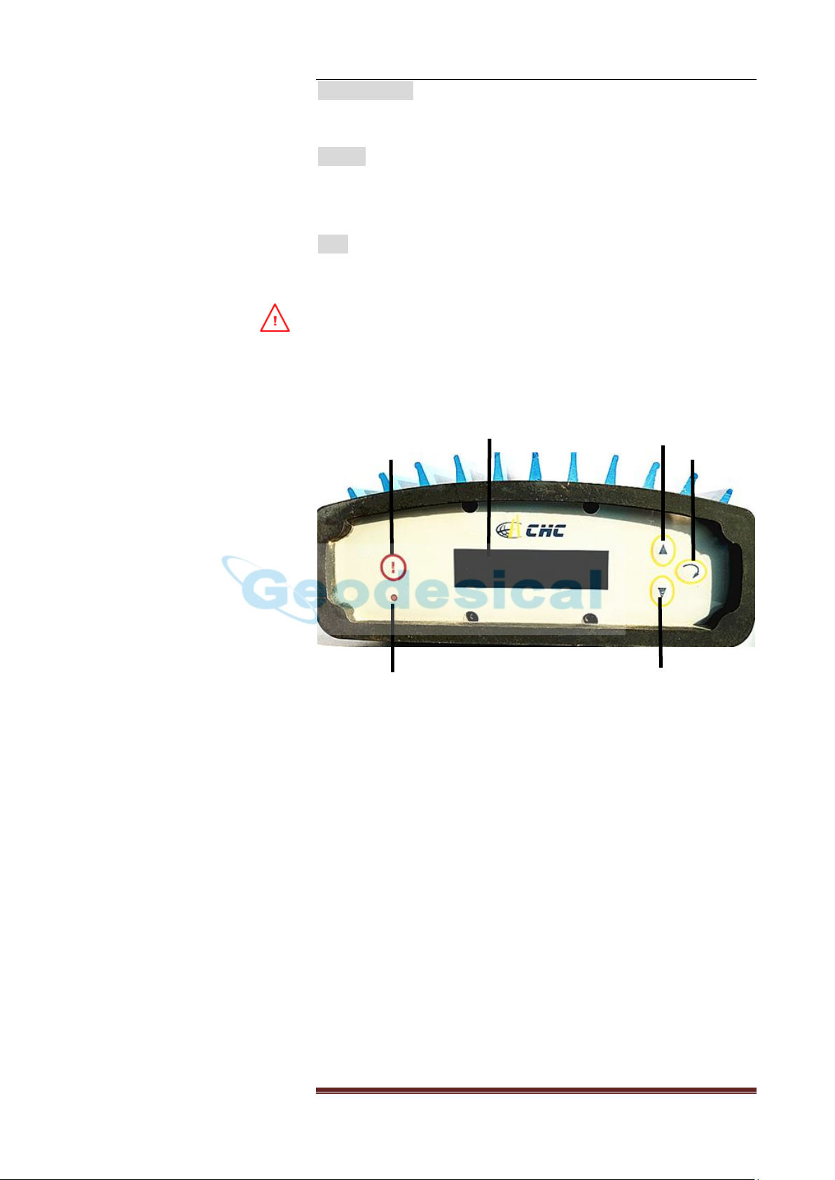
Power
Screen
Up
Enter
Down
LED
Figure5.2.2-3
Radio antenna: This socket is for fixing CHC made antenna on the
Radio.
Battery: This socket is for using CHC made power cable to link
the Radio to the Car battery (insuring the red point match the red
point).
Data: This socket is for using CHC made data cable to link the Radio
to the receiver.
WARING: There is sequence for the cables linking to DL3: firs please
fix the radio antenna, and then power cable, and last the data cable.
3. Control panel
Power Button: When you press this button, the front page will show
on the screen
LED: This LED will flash once per second when the radio successfully
sends out the correction data.
Screen: The system information and setting information of the
datalink would be showed inn the LED screen.
Up Button: when you press this button, the cursor on the screen will
move up
Down Button: when you press this button, the cursor on the screen
will move down.
Enter Button: when you press this button, it will make the
configuration work.
22
Page 26

Start Surveying Work
Figure5.2.2-4
Figure5.2.2-5
Figure5.2.2-6
Figure5.2.2-7
Figure5.2.2-8
Figure5.2.2-9
Figure5.2.2-10
Figure5.2.2-11
Figure5.2.2-12
4. Configuration
When you switch on DL3, you will see this picture
1) Reading the current configuration of Radio
Choosing icon info and pressing Enter, you will see the current
configuration Baud, Mode, P &F, Temp and Version of the Radio.
CAUTION: The info can be used in the checking after changing the
Radio parameters.
2) Setting the configuration of Radio
Choosing icon Set and pressing Enter, you will see this picture, and
then you can start to set up DL3
A. Baud
Choosing icon Baud and pressing Enter, you will see 3 Baud rate
4800, 9600 and 38400. For CHC Rover station, please choose Baud
rate 9600 and press Enter to make the configuration work.
B. Mode
Choosing icon Mode and pressing Enter, you will see 4 modes, they
are Receive, Transmit, Relay and R&T, if using Radio to transmit the
correction data from Base station to the Rover, please choose
Transmit and press Enter to make the configuration work.
C. Noise
Choosing icon Noise and pressing Enter, you will see it asking you to
find Noise YES or NO to detect where there is one radio station
having the same Frequency.
D. P &F
Choosing icon P&F and pressing Enter, you will see Powset and
Freset.
First, choosing Powset and pressing Enter, setting how much watt
you want then press icon Enter. For CHC DL3 power is from 1W to
20W, and each adding value is 1W.
23
Page 27

Start Surveying Work
Figure5.2.2-13
Figure5.2.2-14
Second, choosing Freqset and pressing Enter, please set frequency
as xxx.050 then press icon Enter.
E. LED
Choose icon LED and press Enter, you will see icon add and sub, you
can choose add or sub and press Enter to regulate the light of
screen.
CAUTION: After changing the radio settings, please choose Enter to
active the setting, otherwise the setting will not come into function.
24
Page 28

Appendix
Appendix A-1
Appendix A-2
Appendix A-3
Appendix A Log Controller on Internet
Comparing to GPRS Mode, DCI Mode also connects to internet by
GPRS NET to get Correction Message, the difference is that the SIM
card is inserted into Controller directly not the Receiver.
Log Controller on Internet
Insert the SIM card into the slot located at the same place as
battery compartment
Establish the internet connection on Controller (e.g. Windows
Mobile 6.1)
- Active Phone function on Controller: click the icon
Phone/Wi-Fi/Bluetooth on the desktop of Controller,
shown as the figure on the left.
- Click Phone icon to active it, then click Done
- To establish a new connection on Controller, follow
the route Start → Settings → Connections Tab →
Connections:
Select Add a New Modem Connection option, give the
new connection a name and select Cellular Line (GPRS)
Modem then click Next. Input the Access Point Name,
Next again, input User name, Password and Domain if
offered by GPRS Servers Provider. Click Finish, in the
new window shown on the left choose Manage
Existing Connections.
- You will see the new connection listed here, long press
the connection name and select Connect from the pop
out list.
25
Page 29

Appendix
Appendix A-4
- Check whether the connection success or not,
compare the two statement on the top of the screen,
shown in the Figure on the left, the first one is the
normal one, the second is succeeded connected.
26
Page 30

Appendix
PIN
Signal Name
Description
1
TXD
Transmit Data(PC receive data through this pin)
2
RXD
Receive Data(PC transmit data through this pin)
3
PWR
External Power Input (9-15 V DC)
4
PWR
External Power Input (9-15 V DC)
5
GND
External Power Ground
6
GND
External Power Ground
7
USB PWR
8 D- 9
D+ 10
Not Used
Appendix B CHC receiver 10 PIN LEMO definition
Last reviewed on Mar 14 2014
27
 Loading...