


A5CN – A6 – A8 (Rev. 01/06/2012) ENG 1
Installation and instruction manual,
Pellet stoves
Mod. A5CN – A6 – A8

2 ENG A5CN – A6 – A8 (Rev. 01/06/2012)
DIMENSIONS
AMANDINE, ADELAIDE, ADELE:
ALESSIA, ANTONELLA, AXELLE:
ALEYNA, ARMELLE, ALINE:

A5CN – A6 – A8 (Rev. 01/06/2012) ENG 3
A = 200 mm
B = 300 mm
C = 800 mm
D = 500 mm
E = 300 mm
B
B
A
D C
E

4 ENG A5CN – A6 – A8 (Rev. 01/06/2012)
B
B
A
D C
E
A = 200 mm
B = 300 mm
C = 800 mm
D = 500 mm
E = 300 mm

A5CN – A6 – A8 (Rev. 01/06/2012) ENG 5
B
B
A
D C
E
A = 200 mm
B = 300 mm
C = 800 mm
D = 500 mm
E = 300 mm

6 ENG A5CN – A6 – A8 (Rev. 01/06/2012)
Dear Customer,
Thank you for choosing one product from our range and we hope you will be fully satisfied.
1. All stoves belongs to the A5, A6 and A8 series (product family identification code) have been build with high
gauge steel (up to 3 and 4 mm for the combustion chamber) of the best quality, and materials like vermiculite
(skamolex) for the inner part of the combustion chamber. This gives a clear vision of the stove but also shows a great
heat resistance and allowed us to gain significant levels of heat output as well as very low gas emission levels
2. For the electric and electronic components, the best suppliers on the European market have been selected. The
main board, actually the heart the stove, has been developed by the market leader with over 1.000.000 parts on th e
market.
3. Other components like smoke exhaust motors, pellet loading system and hot air fans have been selected with the
same concept: only the best available on the market. For exemple, for the pre-heater we could use a cheaper
component but we decided to install a double jacket. This gives us the possibility to install the pre-heater right there
in the fireplace, where the pellet is. Why? To get a fast and safe starting of the stove!
4. On the top of all other checks, electric and for single components, we have added the “FINAL FIRE CONTROL”, a
check we already run since over 10 years for all or gas stoves. At the end of the production we do connect and fire all
stoves and thanks to a special electronic control, do simulate all the typical conditions like in your everyday use. In
this way we make 100% sure each single stove is working 100%.
In other words, we have realized the first “noiseless” stove – plus the A5 one that doesn’t have the ventilation fan -:
all A6 and A8 models are fitted with a special function to switch the vent fan off and run the stove like a natural
convention one
You can program the heating in your house but switch the fan off when getting home at the evening and enjoy in
silence the pleasure of the fire.
All models are fitted with the external air inlet in line with the pre-heater. The outside air is getting warmed in the fire
pot but a part is used to keep the glass door clean. This makes the stove tight and ideal to be installed in class A or
BBC houses.
How could we get this result? First of all by choosing reliable top quality components and, last but not least, adopting
a high sophisticated construction technology. Our target hasn’t been the price but the care of the quality. On the top
of that, our 25 years heating system manufacturing experience and a two years intensive developing program of a
French – Italian technical team. The most innovative pellet stove nowadays available on the market is the result.
Our exclusive overpressure valve is your guarantee for safety even when using not approved pellet quality or
chimney which doesn’t work properly.
How to lock and unlock the remote control keypad:
key 7 and right after key 3
.

A5CN – A6 – A8 (Rev. 01/06/2012) ENG 7
Index ENG
1. IMPORTANT INFORMATIONS ERREUR ! SIGNET NON DEFINI.
2. SAFETY ERREUR ! SIGNET NON DEFINI.
3. HANDLING AND STOCKING ERREUR ! SIGNET NON DEFINI.
4. AUTHORIZED FUEL ERREUR ! SIGNET NON DEFINI.
5. NON AUTHORIZED FUELS ERREUR ! SIGNET NON DEFINI.
6. STOVE DESCRIPTION 10
7. INSTALLATION ERREUR ! SIGNET NON DEFINI.
8. LOCATION OF THE STOVE ERREUR ! SIGNET NON DEFINI.
9. THE SMOKESTACK ERREUR ! SIGNET NON DEFINI.
10. CONNECTING TO THE EXISTING SMOKESTACK 12
11. ALLOWED INSTALLATIONS 14
12. NOT ALLOWED INSTALLATIONS (IN ITALY) 15
13. PASSING THROUG FLAMABLE CEILING 15
14. CONNECTING TO THE EXTERNAL AIR INLET 15
15. ELECTRICAL CONNECTION 16
16. REMOTE CONTROL INSTRUCTIONS 17
17. LIST OF MENUS 18
18. MENU 02 - DAY AND TIME SETTING 19
19. MENU 03 - SET WALL THERMOSTAT 19
20. MENU 04 – SELECT LANGUAGE 21
21. MENU 05 – SET ROOM TEMPERATURE PROBE 21
22. MENU 06 – STAND BY OR STOP&GO 22
23. MENU 07 – BEEPER 22
24. MENU 08 – FIRST PELLET LOADING 22
25. MENU 09 – STOVE STATUS 23
26. MENU 10 – SERVICE SETTINGS 23
27. MENU 11 – DEALER SETTINGS 23
28. MENU 12 – FAN ENABLE (ONLY FOR A6 AND A8 MODEL) 23
29. STOVE STARTING 23
30. ROOM TEMPERATURE SETTING 24
31. POWER SETTING 24
32. SWITCHIN STOVE OFF 24
33. REMOTE CONTROL FREQUENCY SETTING 25
34. REMOTE CONTROL LINKING 25
35. HOW TO USE THE REAR CONTROL PANEL (IN EMERGENCY ONLY) 26
36. FIRST STARTING 27
37. MAINTENANCE AND CLEANING 28
38. ELECTRICAL DIAGRAM 29
39. TROUBLESHOOTING 30
40. MOUNTING LATERAL CERAMIC 32
41. GUARANTEE 34

8 ENG A5CN – A6 – A8 (Rev. 01/06/2012)
1. IMPORTANT INFORMATIONS
This instruction manual belongs to the pellet stove and is delivered with it. The stove is delivered with this manual,
the relevant plant booklet and the guarantee form. Please do carefully read this instruction manual before installing
and starting the stove. Save all the a.m. documents because they are integral parts of the stove.
CAUTION: This warning symbol located in various parts of this book, indicates
that if you don’t follow the intructions of what is written, it can cause serious
damages to the product and endanger the safety of those users.
For safety reasons, it is very important to always follow instructions when maintaining the stove.
All the local, regional, National and European regulations have to be satisfied when using
this stove.
The packaging does protect your stove. However, during transport, the stove could get damaged. Therefore, we
kindly ask you to carefully check the stove and its components. A damaged stove - or in case of missing component
– should not be installed. Please get immediately in touch with your dealer.
2. SAFETY
Attention: the glass is very hot !!!! Do not leave kids near the stove!!!
Do not leave curtains, clothes, dish closes, furniture or other material on or near to the stove. Do respect the safety
distances.
After installing the stove let it burn at an average power (power 3).
Ventilate the room and carefully supervise the stove. During this time, all paints and assembling material will dry out.
The light smoke that could develop will rapidly fade away.
Regular maintenance and cleaning are essentials for the stove proper working and lasting. Check for craked or
broken glasses. In case, replace immediately.
Your stove has been developed for using a well defined fuel. Specification for the ideal fuel is shown in the next
chapter. In case of use of different or not allowed fuels, your stoves can get shortly damaged.
The remote control does integrate a probe and you can set the desired temperature for the room where the remote is
located. The range is 7 to 8 meters depending on the architecture of the building. We suggest not placing it close to
the stove. All side walls and the top of the stove are getting very hot. Do not leave there the remote because it will be
damaged.
Always use original parts for the guarantee. It is not allowed to modify in any way the stove.
Basic safety rules:
General Indications:
- Never use water for extinguishing a stove.
- The glass and other parts of the stoves are extremely hot and could be very dangerous for kids
- Through the glass, there is a radiant heat, don’t put flammable materials, heat sensitive objects or people at less
than 80 cm by 180°.
- Don’t leave flammable materials near to the stove.
- Never run the stove when the ashtray is out
- When cleaning the ash tray and burning pot, put all rests in a metallic container and wait at least 48 hours before
discarding it in order to prevent fire cases.
After sale service
We recommend you to always order only original spare parts directly supplied by the stove manufacturer otherwise
the guarantee will decline.
The manufacturer is not responsible for maintenance and cleaning operations made unaccordingly with this manual.

A5CN – A6 – A8 (Rev. 01/06/2012) ENG 9
3. HANDLING AND STOCKING
The cardboard/wood package has been designed to protect the
stove but cannot be stocked outside or in very damp places. It
must be exposed to the elements, otherwise some components
or the stove itself could get damaged and the guarantee will
decline. As stoves have some fragiles parts like glasses and
electronic components, it should be handled following few basic
rules:
Lift and lay down the stove gently. In case you use a two wheels
trolley or when transporting upstairs, always take the stove at the
side opposite to the glass (which is identified by a sticker). The
glass is always placed on the sticker side.
.
4. AUTHORIZED FUEL
Pellet is produced with wood rests from clean wood machining like sawmills, furniture manufacturing or new wood
from forest culture. All these 100% vegetable materials are dried and pressed into the pellet form without adding any
kind of glue or chemical. We do approve to be used in our stoves all pellets that satisfy the European regulation EN
14961-2. All the approved pellets must carry the following logo:
New logo since 2011
Typical specifications for the approved fuel:
.caloric capacity (in MJ/kg) (2*)
. ≥ 17,6 MJ/kg
.caloric capacity (in KWh/kg) (2*)
≥ 4,9 KWh/kg
.caloric capacity (in Kcal/kg) (3*)
≥ 4.223 Kcal/kg
..density
..1,12 kg/dm3
..water content
..mass. 10,0 %
..ash content
..mass. 0,5 %
..length
..mass. 30 mm
..diameter
5- 6 mm
..thin material (rests)
..mass. 2,3% (1*)
..composition
..natural wood
If using a low quality fuel, the stove could possibly work not properly and can lead the guarantee to decline.
The uses of low quality pellet leads to:
- Shorter cleaning intervals
- Higher fuel consumption
- Lower output
- Glass getting quickly dirty
- Fire pot and exhaust smoke connection will clog up rapidly
5. NON AUTHORIZED FUELS
All pellet types that doesn’t satisfy the a.m. indications..

10 ENG A5CN – A6 – A8 (Rev. 01/06/2012)
6. STOVE DESCRIPTION
Remote control
Flap door for
charge pellet
Protection grid
Fire pot
Air-glass cleaning
Fire pot support
Ashtray
Flap door inspection
lower smoke chamber
Inner glass ceramic
Closing door
Door
Charge pellet in fire pot
Interior in skamolex
Convection air outlet
Overpressure security valve
Handle opening door
Make sure the power supply is always available
Rear control panel
Room temperature probe
Wall thermostat connecting
Air inlet for combustion
(chose one of two solutions)
Fuses
Electrical connection
On / Off switch
Smoke piping
Starting resistance

A5CN – A6 – A8 (Rev. 01/06/2012) ENG 11
IMPORTANT: ALL PICTURES AND DRAWINGS LISTED IN THE MANUAL ARE
ONLY INFORMAL. THE INSTALLATION MUST TO BE CONFORM TO THE LOCAL
AND NATIONAL REGULATIONS FOR INSTALLATION.
Before installing the stove please check as follows:
- The chimney has to be correctly designed for exhaust gases and must satisfy the requirements for the stove
- The distance between stove and flammable materials has to be respected
- The wall back to the stove must satisfy the regulations in force and manufacturer’s recommendations
- The external air intake must be the right size and connected to the stove
- Floor capacity is enough related to stove weight
8. LOCATION OF THE STOVE
If the stove is located on a flammable floor (i.e. parquet), you will have to protect it against radiant heat and
eventually some combustion rests with appropriate non flammable materials (steel, marble, tiles etc.).
Minimum distances to be respected are shown below and in the first page of this manual:
If scaffoldings are placed over the stove, a minimum distance of 50 cm from the stove itself and from the chimney
has to be respected. A distance of min 50 cm between the chimney and heat sensitive building elements like facing,
beams or wooden ceilings, etc. must be respected
Keep all flammable materials like wooden furniture, curtains, carpets and
flammable fluids at least 80 cm from the stove when operating).
9. THE SMOKESTACK
Each stove should be only connected to a single chimney. The chimney pipe must be built in a proper way to
facilitate cleaning and inspection. All chimneys and connection piping must be identified by an approved tag showing
all typical data in accordance with local and national regulations in force.
MIN 50 cm
MIN 50 cm

12 ENG A5CN – A6 – A8 (Rev. 01/06/2012)
Smoke evacuation system components designation example:
Temperature class (es: T400 minimum, T450-T600 suggested)
The smokestack temperature class should not be lower than the maximum exhaust gasses temperature declared by
the stove manufacturer.
For all appliances (appliances for home heating burning wooden pellet as fuel – requirements and testing procedure)
temperature class lower than T400 are not allowed. In any case always check the stove data sheet for technical
details but temperature Txxx should be at least 50 °C higher than the maximum smoke temperature.
Pressure class (smoke tightness) N
Since all smokestacks must work in depression, the pressure class will be N = negative
By the end a smokestack showing this tag is perfect to fit a pellet stove: T450N1D2GXX
Soot fire resistance class G
All smokestacks connect to appliances burning solid fuel must be soot fire resistant; the designation letter will
therefore be G followed by the distance in millimeters (XX) (as per UNI EN 1443) from flammable materials. The
chimney has to be built in accordance with the local and national regulations in force.
10. CONNECTING TO THE EXISTING SMOKESTACK
The connection to the existing smokestack has to fulfill the the local and national regulations in force. Piping with
classification “O” and minimum distance in millimeters xx is allowed and ensures that in case of soot fire all
connecting piping will be fully replaced in order to restore the original conditions. Please make sure only 3 direction
changing of maximum 90° and a 4 meters horizontal segment are allowed (check following examples) .
Example with 2 bends 90° Example with 3 bends 90° (maximum allowed)
The stove can be connected to an existing smokestack only after carefully checking it. If the smokestack doesn’t
show the approved tag, a registered chimneysweeper has to certify it.
Metal chimney
Regulation ID number
Temperature class (as per UNI EN 1443)
Pressure class N, P or H (as per UNI EN 1443)
Moisture resistance class (as per UNI EN 1443)
Corrosion resistance class (as per UNI EN 1443)
Soot fire resistance class G or O Followed by the distance from flammable materials
EN 1443 T400 N1 D 2 G50
1
2
3
m
a
x
1
,
5
m
1
2
3
1
2
m
a
x
4
m
i
n
c
l
i
n
a
t
i
o
n
>
3
%
i
n
c
l
i
n
a
t
i
o
n
>
3
%

A5CN – A6 – A8 (Rev. 01/06/2012) ENG 13
When connecting to non isolated smokestacks, draught problems can occur. It is however forbidden to connect the
stove to the smokestack with a diameter bigger than 200 millimeters (in the case slot - a 100 / 150 millimeter pipe up
to 4 meters or a 150 / 180 millimeters one over 5 meters of smokestack height). Always follow the local and national
regulations in force.
CONNECTOR T WITH CAP
A HERMETIC CLOSING
CONNECTOR
ø 80 > ø 100
ø 80mm
ø 100mm
STOVE
INSULATING
CONNECTOR T
CONNECTOR T
CLEANING
DIRECTION
CLEANING
DIRECTION
M
a
x
4
m
(
m
i
n
.
3
%
)
CLEANING DIRECTION
ø 100 mm
min.
CHIMNEY
TCONNECTOR
Ø 80mm
INSULATING
Ø 180mm MAX
Ø 100mm MIN
INSERTING
OF A TUBE
INSPECTION
COVER
NOT INTEGRATED FLUE
DUCTING WITH
CLOSING FLANGE
CLOSING FLANGE IN HERMETIC
STAINLESS STEEL OR ALUMINATE
OUTDOOR AIR SUPPLY
WITH GRATE NO PACKABLE
DUCTING
EXISTING
FLUE

14 ENG A5CN – A6 – A8 (Rev. 01/06/2012)
11. ALLOWED INSTALLATIONS
Smokestack diameter has to be adequate to its height as is the following sketches.
The use of insulated smokestacks is recommended in all the following cases:
- All outside smokestacks.
- When getting through non heated attics or mansards
- Very long segments (over 4 meters) inside the apartment.
INSULATING
INSULATING
CLEANING
DIRECTION
M
a
x
4
m
(
m
i
n
.
3
%
)
CLEANING DIRECTION
CLEANING
DIRECTION
OK
M
a
x
4
m
(
m
i
n
.
3
%
)
CLEANING DIRECTION
NO
CLEANING DIRECTION
OK
Ø 80 mm
MAX 3 meters
Ø 100 mm
MAX 6 meters
Ø 150/180 mm
MAX 15 meters
INSULATING
INSULATING

A5CN – A6 – A8 (Rev. 01/06/2012) ENG 15
Following sketches are wall exhaust examples for the countries where it is allowed.
12. NOT ALLOWED INSTALLATIONS (In Italy)
1) Two or more stoves connected to the same smokestack.
2) Stove and fireplace connected to the same smokestack.
For all other countries, respect all local and national regulations in force.
13. PASSING THROUG FLAMABLE CEILING
Be very careful when getting through walls, ceilings or roofs made of flammable materials.
The high smoke temperatures can start a fire. Always respect the safety distances of your
local and national regulations in force.
14. CONNECTING TO THE EXTERNAL AIR INLET
The air inlet diameter should be not less than 60 millimeters and the maximum piping length is 1 meter and one 90°
bend. The stove is fitted as standard with a 80 millimeters connection. In this case, the maximum length can be 1,5
MIN 2 meters
MIN 1,5 meters
INSULATED
PIPE
Inclination > 3%
Length < 3 m

16 ENG A5CN – A6 – A8 (Rev. 01/06/2012)
meters and one 90° bend. When connecting the stove with an external air inlet, you will get an exceptional level of
comfort and operation softness. The stove will properly burn even in case you can’t connect it to an external air inlet
but getting the combustion air from the inside of the room.
15. ELECTRICAL CONNECTION
Check that the wall plug is in accordance to the stove electrical requirements: 230V/50Hz e 400Watt. Make sure that
the electrical cord doesn’t get in touch with any hot part of the stove and doesn’t run over the smoke connection, that
a proper earth is available and a proper circuit breaker is fitted. In case of irregular power supply (normally in remote
or mountain areas), do not worry, your stove is protected with two 5X20 4A STD between the main switch and the
cord plug on the rear panel. Check the fuses before installing the stove.

A5CN – A6 – A8 (Rev. 01/06/2012) ENG 17
16. REMOTE CONTROL INSTRUCTIONS
The remote control works up to a maximum distance of 8 meters and allows you
operating your pellet stove.
› Button 1 - Navigation
To reduce temperature and power output and scrolling down worth the menu.
› Button 2 - Navigation
To increase temperature and power output and scrolling up worth the menu.
› Button 3 - ON-OFF and BACK
Hold for 3 seconds for switching the stove on and off. Press once for getting back into
the menu till home page.
› Button 4 - ROOM TEMPERATURE SETTING
Press for entering the room temperature setting menu with buttons 1 and 2.
› Button 5 - POER OUTPUT SETTING
Press for entering the power output level 1 to 5 setting menu with buttons 1 and 2.
› Button 6 - Not in use
Not in use.
› Button 7 - MENU and OK
Press for entering the main menu than use buttons 1 and 2 for scrolling; press button
7 again for entering the desired sub menu.
Press to confirm selection (OK).
› Display
All the needed information are displayed (the aboce schema represents the starting
screen):
If no buttons are pressed for 30 seconds after switching on the stove the remote
control enters the stand-by status and the display goes off. Press any button to
reactivate.
To lock or unlock the keyboard: button 7 and button 3 in rapid sequence.
The remote control is supplied with a wall rest.
Do not place the remote control near the stove or close to other heat sources. For best
results, we suggest to locate it at a height of 150 centimeters. The maximum operating range of 8 meters from the
stove depends on architectonical barriers (walls). The remote control should be handled with care and not exposed
to the weather (sun, rain). The control is fitted with AAA cells (included). Change batteries every year or when low.
Remove the cover on the backside to access the battery location. Please dispose flat batteries properly. In case of
doubts, check with your local recycling center.
When programming the stove using the remote control, the clock stops, so if you use
with the remote control for a long time, you will find that the display not indicate more
the exact time. The clock goes programmed every time you use for a long time with the
remote control.
TOLERANCE INDICATOR OF TEMPERATURE ON THE REMOTE CONTROL is + or - 3 ° C
18 ENG A5CN – A6 – A8 (Rev. 01/06/2012)
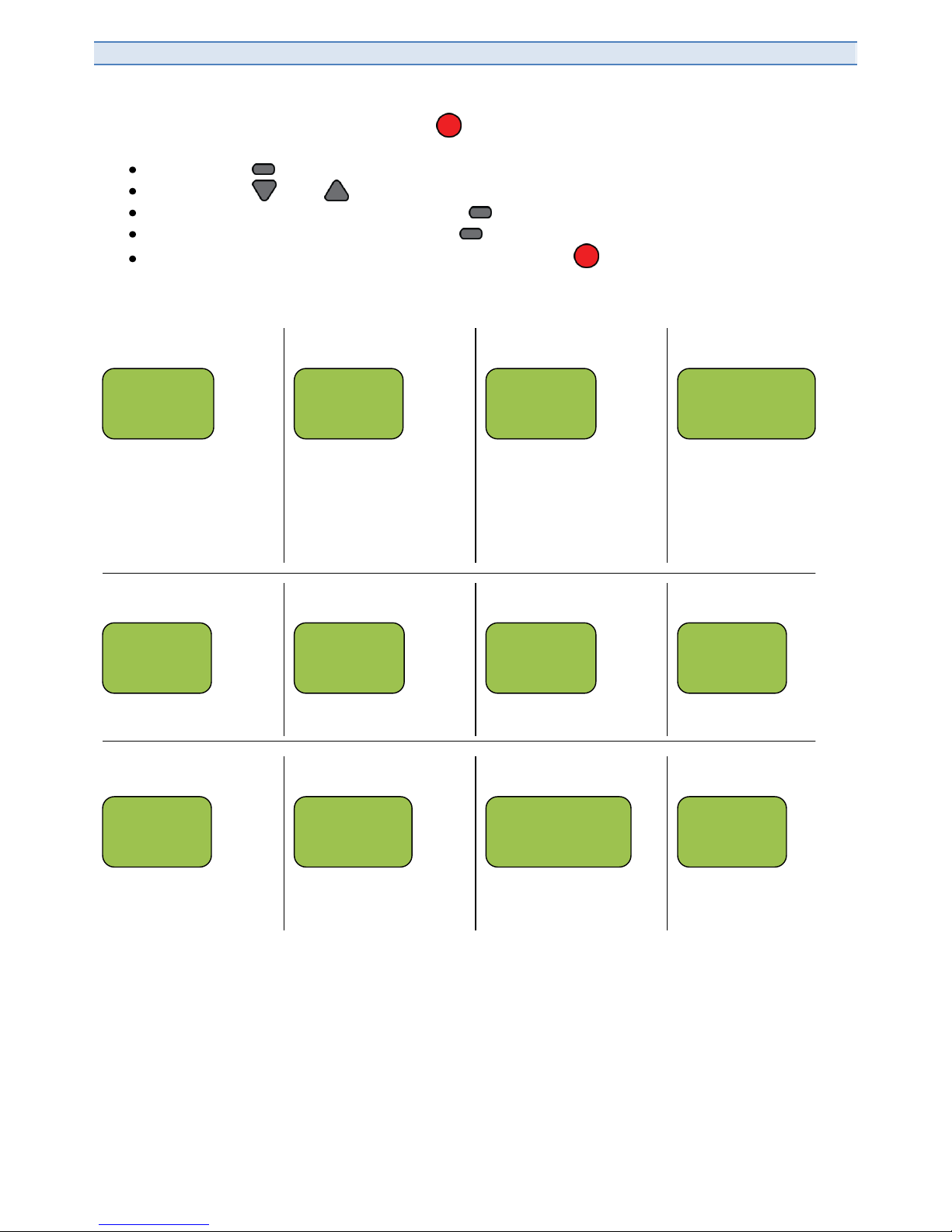
17. LIST OF MENUS
After switching the remote control on (press button3 ),
Access the different menus for programming the stove:
Press button 7 to access the main menu (MENU 1 on the display)
Press button 1
and 2
to scroll all menus 1 to 12
When selected the desired menu, press button 7 to confirm.
Confirm the different options (OK) with button 7 .
To exit the menus and getting back to main menu, press button 3
.
.
MENU 01
ADJUST BLOWER
Disabled menu.
MENU 02
SET CLOCK
> Day (Monday – Sunday)
> Hours (00 – 24)
> Minutes (00 – 59)
> Date (01 – 31)
> Month (1 – 12)
> Year (00 – 99)
MENU 03
SET THERMOSTAT
> Week setting (ON/OFF)
> Start program – 1
(OFF, 00:00 – 24:00)
> Stop program – 1
(OFF, 00:00 – 240:00)
10 minutes interval
MENU 04
SET LANGUAGE
> Italian ITA
> French FRE
> English ENG
> German DEU
MENU 05
SET PROBE
> Inside probe
> Remote control probe
MENU 06
STAND-BY
> On
> Off
MENU 07
BUZZER
> On
> Off
MENU 08
STARTING LOAD
To be used by the starting
only
MENU 09
STOVE STATUS
Close menu.
All indication on stove
status are given
MENU 10
SERVICE SETTINGS
Code access menu for
qualified service use only
MENU 11
DEALER SETTINGS
Code access menu for
qualified dealer use only
MENU 12
SET FAN
> On
> Off
For models A6/A8 only
MENU 01
ADJUST
BLOWER
MENU 02
SET
CLOCK
MENU 03
SET
CHRONO
MENU 04
SELECT
LANGUAGE
MENU 05
SELECT
FEELER
MENU 06
MODE
STAND-
MENU 07
MODE
BUZZER
MENU 08
LOAD
INITIAL
MENU 09
STATE
STOVE
MENU 10
SETTINGS
TECHNIC
MENU 11
SETTINGS
CLIENT
MENU 12
ENABLE
BLOWER

A5CN – A6 – A8 (Rev. 01/06/2012) ENG 19
18. MENU 02 - DAY AND TIME SETTING
1) From main
menu…
2) Press button
7 for accessing
menus
3) Menu 01 is
displayed
4) Press button
2 for scrolling all
menus
5) Show menu
02
6) Press button
7 for entering
the menu
7) Display the
week day
(Monday –
Sunday)
8) Press button
2 to change the
day
9) Press button
7 to confirm
10) Display the
time (00 – 24)
11) Press button
2 for changing
the time
12) press button
7 to confirm
13) Display
minutes (00 –
59)
14) Press button
2 to set minutes
15) Press button
7 to confirm
16) Day date is
displayed (01 –
31)
17) Press button
2 for changing
date
18) Press button
7 to confirm
19) display
month (01 – 12)
20) Press button
2 to set month
21) Press button
7 to confirm
22) Year is
displayed (00 –
99)
23) Press button
2 for changing
year
24) Press button
7 to confirm and
then button 3.
19. MENU 03 - SET WALL THERMOSTAT
This program enables you setting a fire or power off interval for each week day. You can schedule up to 4 different
on/off programs. The following example shows a typical program for a family with children. On/OFF intervals are set
to satisfy the school time table of the children as well as the week end warm requirements when the whole family is
remaining home.
Monday
Tuesday
Wednesday
Thursday
Friday
Saturday
Sunday
PROG 1 : from 5h00 to 9h00
PROG 2 : from 18h00 to 23h00
PROG 3 : from 13h00 to 23h00
PROG 4 : from 9h00 to 23h00
Attention: before programming the CRONO function, you have to set day, date and time (menu 02 - SET TIME).
14 :34
28.5 P-1
OFF
MENU 01
ADJUST
BLOWERS
MENU 02
SET
CLOCK
MENU 02
SUNDAY
DAY
10
MENU 02
TIME
CLOCK
: 09
MENU 02
MINUTES
CLOCK
23
MENU 02
DAY
CLOCK
10
MENU 02
MONTH
CLOCK
11
MENU 02
YEAR
CLOCK

20 ENG A5CN – A6 – A8 (Rev. 01/06/2012)
MENU 03 - SET WEEK THERMOSTAT
1) From main
menu…
2) Press button
7 for accessing
menus
3) Menu 01 is
displayed
4) Press button
2 for scrolling all
menus
5) Show menu
03
6) Press button
7 for entering
the menu
7) Program
on/off displayed
8) Press button
2 for enable
program (ON)
9) Press button
7 to confirm
10) Starting time
program 1 is
displayed but
disabled (OFF)
11) Press button
2 for enables
the program
(ON)
12) Starting time
program 1 is
displayed
13) Press button
2 for changing
starting time (10
minutes steps)
14) In this
example starting
time at 05:00
AM is shown
15) Press
button7 to
confirm starting
time
16) Switch off
time program 1
is displayed but
disabled (OFF)
17) Press button
2 for enables
the switch off
time
18) Program 1
switch off time is
displayed
19) Press button
2 for changing
switch off time
(10 minutes
steps)
20) In this
example switch
off time at 09:00
AM is shown
21) Press
button7 to
confirm switch
off time
22) First week
day Monday
with program 1
is displayed
23) Press button
2 for enabling
(ON) program 1
for that day
24) Press button
7 to confirm and
start
programming
the next day
25) repeat all
points from 23)
to 24) for each
single day of the
week…
26) …after
Sunday,
program 2 will
be displayed
27) repeat all
points from 11)
to 25) for the
remaining 3
programs
28) When
finished press
button 3 to
confirm
29) Press button
3 to exit back to
menus
2
mere tasto 7 per
confermare e
14 :34
28.5 P-1
OFF
MENU 01
ADJUST
BLOWERS
MENU 03
SET
CHRONO
OFF
MENU 03
CRONO
WEEKLY
OFF
MENU 03
START
PROG-1
00 00
MENU 03
START
PROG-1
05 00
MENU 03
START
PROG-1
OFF
MENU 03
STOP
PROG-1
00 00
MENU 03
STOP
PROG-1
09 00
MENU 03
STOP
PROG-1
OFF
MENU 03
MONDAY
PROG-1
OFF
MENU 03
START
PROG-2

A5CN – A6 – A8 (Rev. 01/06/2012) ENG 21
MENU 03 - WALL THERMOSTAT ENABLING AND CONNECTING
1) From main
menu…
2) Press button
7 for accessing
menus
3) Menu 01 is
displayed
4) Press button
2 for scrolling all
menus
5) Show menu
03
6) Press button
7 for entering
the menu
7) Program
displayed but
disabled (OFF)
8) Press button
7 to confirm
8) Press button
3 to back to the
menu
9) Connect to
the plug on
stove’s rear
panel ….
10) … by mean
of two wires
as….
11) … wall
thermostat
electrical
diagram
20. MENU 04 – SELECT LANGUAGE
This menu allows selecting the desired language among Italian (ITA) which is the default selection, English (ENG),
French (FRE) and German (DEU)
.
1) Select menu
04 (button 7 and
then button 2)
2) Press button
7 to enter the
menu
3) The selected
language is
displayed ENG
(English)
4) Press button
2 for selecting
the desired.
5) Press button
7 to confirm.
6) Press button
3 to back the
menu.
21. MENU 05 – SET ROOM TEMPERATURE PROBE
This menu allows switching the desired room temperature probe on selecting between the remote control probe
(REMOTE) and the one located on the stove’s rear panel (INTERN). As default we suggest using the remote control
probe.
1) Select menu
05 (button 7 and
then button 2)
2) Press button
7 to enter the
menu
3) Probe in use
INTERN or
REMOTE is
displayed
4) Press button
2 to select the
desired probe.
5) Selected
probe INTERN
or REMOTE is
displayed
6) Press button
7 to confirm and
button 3 to back
to the menu
14 :34
28.5 P-1
OFF
MENU 01
ADJUST
BLOWER
S
MENU 03
SET
CHRONO
OFF
MENU 03
CRONO
WEEKLY
MENU 04
SELECT
LANGUA
GE
MENU 04
ENG
LANGUA
GE
MENU 05
SELECT
FEELER
Menu 0 5
INTERN
PROBE
Menu 0 5
REMOTE
PROBE

22 ENG A5CN – A6 – A8 (Rev. 01/06/2012)
22. MENU 06 – STAND BY or STOP&GO
This menu allows choosing between two functions:
- ON: after few minutes when the set room temperature has been reached the stove switch off and will automatically
switch on again by room temperature decreasing 2 to 3°C (is safety requirements are satisfied).
- OFF (default and suggested setting): when the set room temperature has been reached the stove doesn’t switch off
but continue burning at the minimum thermal output; by room temperature decreasing 2 to 3°C the stove will
automatically increase its thermal output.
1) Select menu
06 (button 7 and
then button 2)
2) Press button
7 to enter the
menu
3) The OFF or
ON setting will
be displayed
4) Press button
2 to select the
setting.
5) Press button
7 to confirm
6) Press button
3 to back to the
menu
23. MENU 07 – BEEPER
This menu allows to enable (ON) or disable(OFF) the confirmation “beep” for all remote control operations.
1) Select menu
07 (button 7 and
then button 2)
2) Press button
7 to enter the
menu
3) The OFF or
ON setting will
be displayed
4) Press button
2 to select the
setting.
5) Press button
7 to confirm
6) Press button
3 to back to the
menu
24. MENU 08 – FIRST PELLET LOADING
This menu allows filling the feeding screw when first loading pellet into the relevant fuel tank.
Attention: this program should be run when first starting the stove or when the pellet tank goes empty
(maintenance, clearing, run out of pellet) otherwise the stove will not start because of lake of fuel in the fire pot. This
operation can only be done when the stove is cold.
.
1) Select menu
08 (button 7 and
then button 2)
2) Press button
7 to enter the
menu
3) The OFF
setting will be
displayed
4) Press button
1 for loading
pellet
5) After 90” the
feeding screw
will stop
6) Press button
7 to confirm and
button 3 to back
to the menu
MENU
06
MODE
STANDBY
OFF
MENU 06
MODE
STANDBY
MENU 07
MODE
BUZZER
ON
MENU 07
MODE
BUZZER
MENU 08
LOAD
INITIAL
OFF
MENU 08
P1 TO
LOAD
90’’
21.0 P - 1
LOAD
INITIAL

A5CN – A6 – A8 (Rev. 01/06/2012) ENG 23
25. MENU 09 – STOVE STATUS
This menu gives advanced information on the stove status and has to be use by dealer’s authorized personnel only.
.Here are the matches of the state indicated on the display:
STATUS 0 = STOVE OFF
STATUS 1 = STOVE ON
STATUS 2 = STOVE WAS ON HOLD or HOLD FIRE BURNOUT
STATUS 3 = FIRE PRESENT
STATUS 4 = STOVE WORK
STATUS 5 = BURNER CLEANING
STATUS 6 = FINAL CLEANING
STATUS 7 = STOVE WAS WAITING FOR COOLING FROM STAND-BY
STATUS 8 = ALARM WAS ACTIVE IN STOVE
STATUS 9 = STOVE WAS IN MEMORY ALARM
26. MENU 10 – SERVICE SETTINGS
To be entered by trained service center technicians only (password required).
27. MENU 11 – DEALER SETTINGS
To be entered by trained dealer technicians only (password required).
28. MENU 12 – FAN ENABLE (only for A6 and A8 model)
Allows selecting one of two options:
- ON fan enabled.
- OFF fan disabled (fan goes however automatically on in case of overheating – over 250 °C – in order to cool the
stove down within safety parameters, than the fan goes automatically off).
1) Select menu
12 (button 7 and
then button 2)
2) Press button
7 to enter the
menu
3) The OFF or
ON setting will
be displayed
4) Press button
2 to select the
setting.
5) Press button
7 to confirm
6) Press button
3 to back to the
menu
29. STOVE STARTING
After having correctly installed the stove do as follows for starting it:
- fill the stove’s pellet tank up
- run the first pellet loading program (MENU 08) at first starting only.
- follow this procedure:
1) Press red
button 3 for 3
seconds
2) START will
be displayed.
3) After some
10” “LIGHTERWAIT“ will be
displayed.
4) After some 1’
“LOAD PELLET”
will be
displayed.
5) After some 3’
“FIRE WAIT” will
be displayed.
6) After some 4’
“FLAME LIGHT”
will be displayed
MENU 12
ENABLE
BLOWER
ON
MENU 07
ENABLE
BLOWER
14 :00
28.5° P-1
START
14 :00
28.5° P-1
LIGHTER
WAIT
14 :01
28.5° P-1
load
PELLET
14 :04
28.5° P-1
FIRE
WAIT
14 :08
28.5° P-1
FLAME
LIGHT

24 ENG A5CN – A6 – A8 (Rev. 01/06/2012)
7) After some 2’ “WORK” will be displayed; this means the stove is correctly working and the burning is constant.
Now you can set both room temperature and thermal output. The fan will automatically start when the heat
exchanger temperature will reach the correct level. When the stove is in use CLEANING CRUCIBLE will be
displayed after each hour burning and will automatically disappear after the self clearing procedure being performed.
.
30. ROOM TEMPERATURE SETTING
Desired room temperature can be set.
When room temperature value being reached the stove switches in the modulation status and “WORK MODULAT”
will be displayed.
1) Press button
4 to enter the
temperature
menu
2) Set
temperature is
displayed
3) Press button
1 for decreasing
temperature
4) Press button
2 for increasing
temperature
5) Press button
7 to confirm
6) Press button
3 to back to
main menu
31. POWER SETTING
Desired power level can be set (from 1 to 5). Much higher the selected power level, much quicker the stove will reach
the set room temperature.
1) Press button
4 to enter the
temperature
menu
2) Set power is
displayed
3) Press button
1 for decreasing
power
4) Press button
2 for increasing
power
5) Press button
7 to confirm
6) Press button
3 to back to
main menu
32. SWITCHIN STOVE OFF
When you switch the stove off by pressing red button 3, the switching off procedure will start, but both fan and smoke
fan will work till the safety stove temperature will be reached.
1) Press and
hold red button
3 for some 3’’
2) “CLEANING
FINAL” will be
displayed
3) After some
20’ stove goes
completely off.
14 :10
28.5° P1
WORK
20°
SET
TEMP
ROOM
03
SET
POWER
14 :15
28.5° P-1
CLEANI
NG
FINAL
14 :34
28.5° P1
OFF

A5CN – A6 – A8 (Rev. 01/06/2012) ENG 25
33. REMOTE CONTROL FREQUENCY SETTING
For avoiding transmission failures in case of radio controller appliances being located near to the stove changing the
remote control frequency is needed (default 0) following the procedure:
1) Press at
same time
buttons 1 and 2
and keep for
some seconds
2) “CHOOSE
UNIT 0” will be
displayed.
3) Press button
2 to select the
radio code: 0, 1
2, or 3
4) Switch the
stove off by
mean of the
main switch
located on the
rear stove’s
panel
5) Switch the
stove on by
mean of the
main switch
located on the
rear stove’s
panel
6) Press red
button 3
7) “UNIT 1
LOADED” (or
unit 0 or 1 or 2
or 3) will be
displaye
8) After some
10” the remote
control switches
back to main
menu
34. REMOTE CONTROL LINKING
In case radio data transmission between remote control and stove doesn’t work properly (high electromagnetic
pollution) it is possible linking the remote control with a dedicated cable (to be ordered as option).
Attention: when linking the remote control to the stove via the cable, batteries must be removed because the
needed power is supplied from the stove.
OIO
I
CHOOSE
UNIT 0
UNIT 1
LOADED
14 :34
28.5° P-1
OFF

26 ENG A5CN – A6 – A8 (Rev. 01/06/2012)
35. HOW TO USE THE REAR CONTROL PANEL (in emergency only)
The rear control panel is designed to be used in emergency cases only, (i.e. remote control failure or loosing
remote)) The heart of the system is the remote control. For this reason, only 2 functions can be operated from the
real panel: on/off and power output setting on steps 2 or 5. It is not possible setting the room temperature.
› Button 3 - On / Off
To switch the stove on: press button for some 3 seconds till the relevant led lights green
To switch the stove off: press button for some 3 seconds till the relevant green led starts
flashing . When the self clearing procedure will be finished it goes out.
› Covering led
This led confirms the remote control transmission has been correctly covered.
› Alarm Led
This led lights on when a failure has been detected. The remote control is necessary to
display the failure that did occur. In case the stove went out of pellet press and keep
button 3 to reset the alarm till red led goes off and green led starts flashing. In all other
cases, do not start the stove but call for service.
› Button 2 - Power output 5
Allows setting the power output on level 5.
Press and keep button 2 for 3 seconds till the relevant led light yellow .
› Button 1 - Power output 2
Allows setting the power output on level 2.
Press and keep button 1 for 3 seconds till the relevant led light yellow .

A5CN – A6 – A8 (Rev. 01/06/2012) ENG 27
36. FIRST STARTING
Fill the tank up with pellet before starting the stove. Remember that the feeding screw is empty and a longer time is
needed when first starting the stove. Run the relevant menu.
When first starting the stove, you can feel bad smells in the room (it’s due to the burning of protection greases
used during production procedure). Do ventilate the room and do not stay in till smells cannot be felt. In order to
supply you with the best possible product, al paints are water based and no harmful thinners are used.
SWITCHIN ON
- Check the cord being connect to the wall plug and for the right voltage.
- Check for the main switch on the rear panel being on ON position.
- Check safety fuse being properly working.
- Check the pellet tank being loaded with a sufficient quantity of pellet for the programmed time of heating.
- Check the remote control working properly and batteries being charged.
- Check day and date settings on the remote control.
- Check the safety flap being properly closed.
- Check the ashtray being properly located in the stove.
- Check the fire pot grid being properly located.
- Check the door being properly closed
FUEL LOADING
- Swing the flap door located on the upper panel up.
- Cut a corner of the bag of and let pellet slowly flow into the tank. Check for any object accidentally being
packed with the pellet.
- Fire alert: do absolutely not leave some pellet on the hot parts of the appliance particularly on the top panel.
- Pellet is packed in plastic or paper bags. Do carefully stock it to allow humidity from damaging it.
- When loading pellet, make sure the bag doesn’t touch hot parts of the stove.
- Check for sawdust in the pellet tank. Vacuum clean weekly.
At stove starting the loading of pellet into the fire pot takes some minutes; during this time the firing
resistance is activated. Usually combustion starts after some 5 to 6 minutes. When the smoke gas
temperature is getting the minimum temperature level the smoke probe transmits to the operating system all
the components are properly working. Now the stove switches to normal burning mode. In the contrary an
error message will be displayed on the remote control (check for error messages).
TURNING STOVE OFF
Press button 3 on/off but do not disconnect the power cord.
The smoke fan and the fan (when fitted) will continue working till the stove will cool down to a safety level.
28 ENG A5CN – A6 – A8 (Rev. 01/06/2012)
37. MAINTENANCE AND CLEANING
Before making any kind of maintenance or cleaning intervention the stove must be switched off, cold and be
disconnected from power supply
For keeping your stove efficient following maintenance and clearing operation must be performer.
Every day cleaning
In order to obtain the best performance from your stove and prolong as much as possible it trouble free working life
you should perform obligatorily every day some simple and quick operations as follows:
1) Ashtray: take it
completely out and empty
ash in a metal can. Wait at
least 48 hours before
discarding for preventing
fire danger.
2) Fire pot: take it
completely out and empty
ash in a can.
3) Protection grid: vacuum
clean all pellet and ash
rests.
4) Glass: clean the glass
with a soft cloth in
combination with our
specific glass cleaner
PULISCI VETRI. Make
sure air adduction slots
being free and clean
Every year:
- Combustion chamber
- Lower smoke chamber
- Smoke fan
- Connection pipe to the smokestack
- Fan if fitted
- Air intake
- Vacuum clean the back side and all electric/electronic components
- Smokestack
Call for a trained serviceman to let all smoke internal connection as well as the smoke fan case to be
cleaned. All mechanical and electronic components will be carefully checked. Our partners located all over
Europe will provide you with the right professional maintenance service.
Smokestack cleaning:
- It is compulsory to call a professional chimney sweeper for brushing the smokestack once a year, or at least
every 1000 kg of pellet but not later than 2 years.
- A cleaning & inspection certificate has to be issued and it will be valid for stove maintenance service as well
as for your home assurance.
- Always check the stove being perfectly working and all gaskets not being worn. All smokestack connections
must be tight and the whole mechanic not being damaged.

A5CN – A6 – A8 (Rev. 01/06/2012) ENG 29
38. ELECTRICAL DIAGRAM
M
M
M
ALP
ALC ALF
thermostat
additional
probe
ambient
+-
230V
Ground
fan smoke
cochlea
main
interchange
electrical resistance
yellow / green
Blue
Pink
White
White
Violet
Green
Gray
Brown
Red
Gray
Orange
Orange
ALF = Safety thermostat General
ALC = Pressure
ALP = Safety thermostat
probe
smoke
fan smoke
Red
Blue
White
Red
Black

30 ENG A5CN – A6 – A8 (Rev. 01/06/2012)
39. TROUBLESHOOTING
Error messages on the remote control display
Trouble: combustion doesn’t start.
Cause: - pellet feeding screw empty.
- Not enough primary air (combustion) because of dirtiness (lack in maintenance)
- Check for the starting resistance
- Check for pellet quality
- check for overpressure switch, could be off because of dirty smoke outlet. Could a
sign the smoke extractor doesn’t work properly
- Check for the safety thermostat.
Solution: check for pellet in the tank. In case you couldn’t slear the problem call for technical
service.
Problem: the stove is far too hot.
Cause: smokestack could be obstructed.
- Canvas or different objects laid on the stoves
- Stove has been installed in a niche without proper
ventilation
- Remote control temperature probe failure
- On board temperature probe failure
Solution: detect the causes. To quit the error signal follow the procedure
1) Unscrew protection cup 2) press safety thermostat button 3) screw the protection
up
Problem: depression hasn’t been build up into the stove.
Cause: - check for all pressure switch connections and the static pressure intake working
properly.
- Check the door being closed and all gaskets not being damaged.
- Check the overpressure flap located on the top of combustion chamber being closed.
- Check all smoke exhaust connection piping and the smokestack (it must be properly
connected and clean).
Solution: go carefully through the a.m. possible causes. If it doesn’t solve the problem, call for
technical service.
Problem: the smoke exhaust fan doesn’t work.
Cause: check all the electrical connections and the wiring to the encoder.
Solution: If it doesn’t work call for technical service.
MANCA
TA
SAFETY
THERMAL
FAILURE
DEPRESS
FAN
FAILURE
NO
LIGHTING

A5CN – A6 – A8 (Rev. 01/06/2012) ENG 31
Problem: pellet doesn’t start burning into the fire pot.
Cause: - Check for pellet tank being loaded.
- Check for loading screw motor not being blocked.
- Check for loading screw not being staged.
- Check the main board.
Solution: go carefully through the a.m. possible causes. If doesn’t solve the problem, call for
technical service.
Problem: refer to smoke probe wiring
Cause: - check the temperature probe.
- check the smoke probe being correctly positioned at the correct depth.
Solution: go carefully through the a.m. possible causes. If doesn’t solve the problem, call for
technical service.
Problem: the stove doesn’t copy the remote control.
Cause: - check the main switch on stove’s rear panel being ON.
- check fuses (4A) located near the main switch and on the electronic board .
Solution: go carefully through the a.m. possible causes. If it doesn’t solve the problem, call for
technical service.
Problem: stove is getting overheated
Cause: - Stove hasn’t been correctly located.
- Smoke piping is staged.
- Combustion chamber is not properly cleaned.
Solution: let the Every Year Cleaning be performed by authorized trained professionals. If it
doesn’t work properly, call for technical service.
NO
PELLET
FEELER
EXHAUST
OUT OF
FIELD
HOT
EXHAUST

32 ENG A5CN – A6 – A8 (Rev. 01/06/2012)
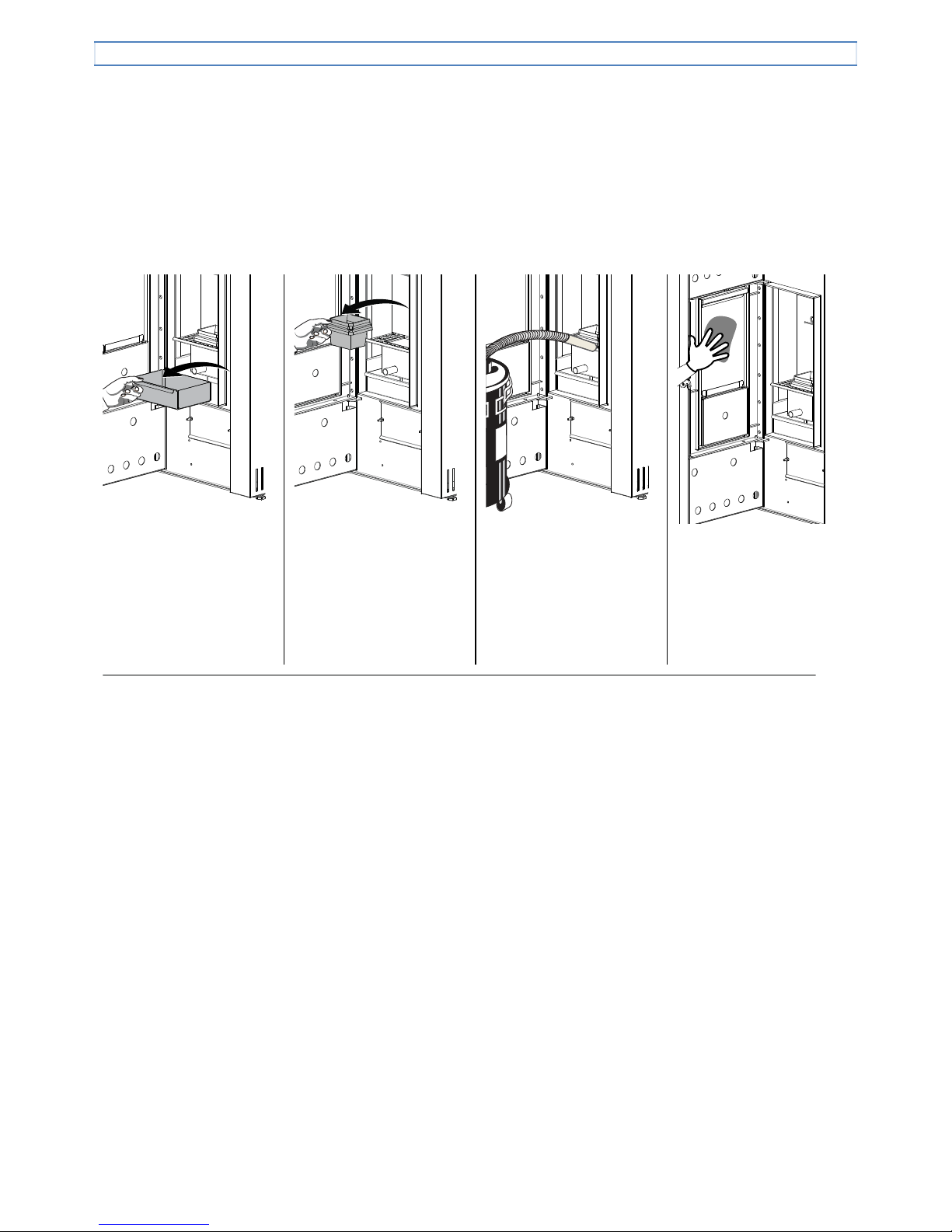
40. MOUNTING LATERAL CERAMIC
The ceramics are provided disassembled to avoid breakage during transport and assembly of the stove. Handle with
great care to avoid damages on the ceramics. Below the procedure for mounting the corners and the cover of the
stove ALESSIA, ANTONELLA, AXELLE:
1) Place the first ceramic corner into
the stove guides.
2) Guide the corner up to the
support bottom.
3) Remove two silicone rubber from
the packaging ...
4) Paste the rubber at either end of
the angle ceramic.
5) Place the second angular
ceramic.
6) Repeat steps 1 through 5 for the
other side.
7) Place the rear cover by inserting
the two pins in the holes on the
uprights of the stove.
8) Paying attention to the hands,
place the cover on the front where it
will be held in place by magnets
adjustable in height.
9) Open the cover of load pellet and
lock the cover to the rear uprights
with bolts supplied.
A5CN – A6 – A8 (Rev. 01/06/2012) ENG 33
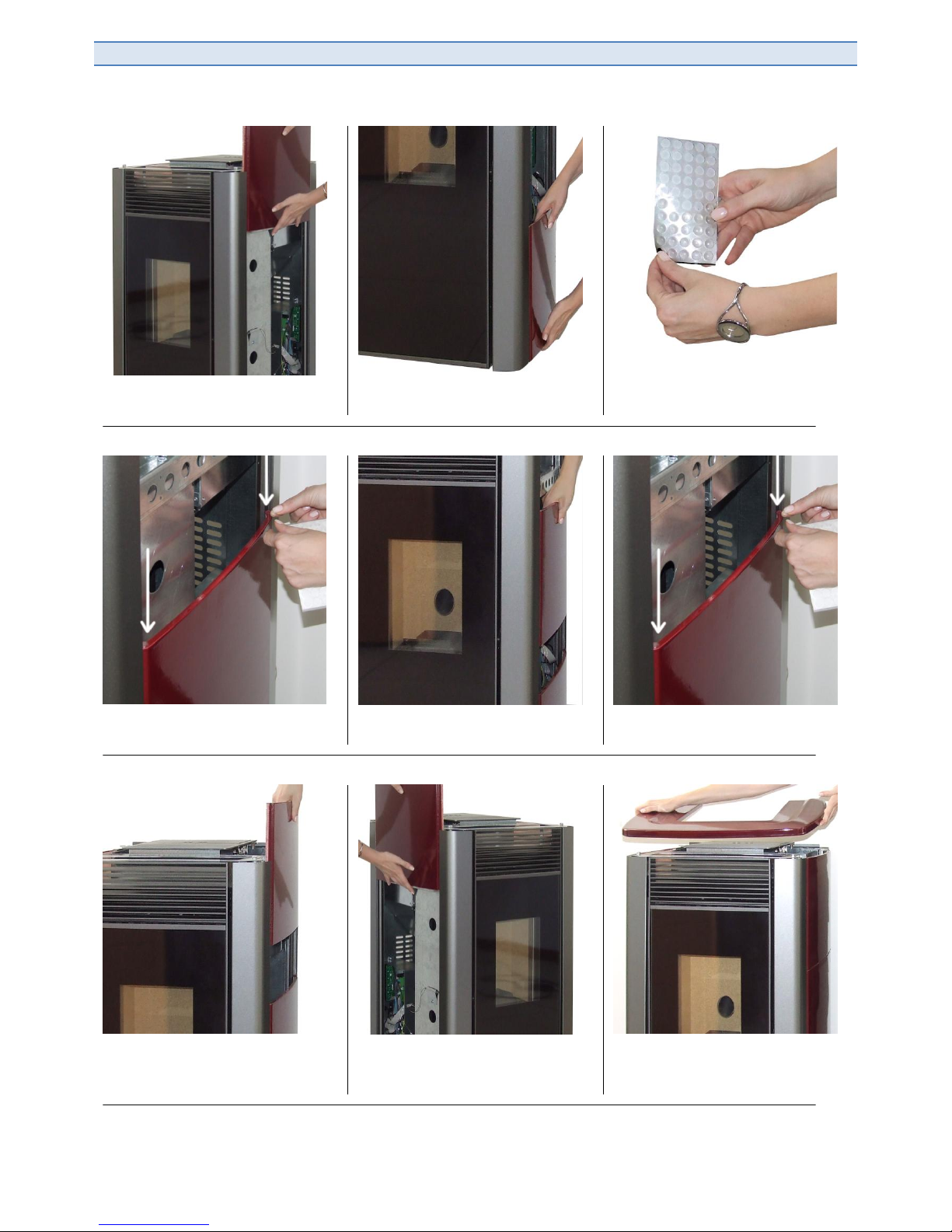
Below the procedure for mounting the sides and top of the ceramic heater Aleyna, Armelle, ALINE:
1) Place the first ceramic side into
the stove guides.
2) Guide the ceramic side up to the
support bottom.
3) Remove two silicone rubber from
the packaging ...
4) Paste the rubber at either end of
the lateral ceramic.
5) Place the second side ceramic. 6) Paste the rubber at either end of
the lateral ceramic.
7) Insert the third ceramic side with
caution.
8) Repeat steps 1 through 5 for the
other side of the stove.
9) Place the top cover in support of
the structure.

34 ENG A5CN – A6 – A8 (Rev. 01/06/2012)
41. GUARANTEE
8.1 – Lasting
The stove is covered by a 2 years guarantee with the exception of all wear and tear components, vermiculite and
gaskets. Guarantee starts from delivery date – purchasing date if bought from a reseller – but stated on the relevant
bill that must always be enclosed.
The guarantee does cover for the time of 2 years all production, components and materials mistakes. All the
damages parts will be checked by our technicians and in case of need substituted free of charge.
8.2 – Validity
The buyer states he went carefully through this installation and instruction manual. The guarantee does only apply to
appliances that have been correctly installed in accordance with the local and national regulations in force
8.3 – Exclusions
8.3.1 wear & tear and refractory components
Al gaskets on door and inspection flaps as well as vermiculite components into the combustion chamber are
considered as wear & tear parts. The guarantee does therefore cover those components for a period of 1 year
starting from delivery date.
8.3.2 Glass
All standard and screened ceramic glasses are eluding from the guarantee.
8.3.3 all ceramic components are handmade. Small marks or differences in color cannot be considered as failures
but a plus being the sign are made one by one as per a centuries old ceramic tradition.
8.3.4 General
All travelling, transport, man craft, packaging, disassembling and down time of the stove rising from the stove repair
in guarantee time are at customer charge.
All components not belonging to the stove but connected to the stove itself, i.e. electronic equipments, are not
covered by the guarantee and are out of our responsibility but not part of the appliance.
In case of using non approved fuels, the guarantee will expire and will not cover all related damages
Guarantee will not be applied in the following cases:
If the installation and assembling is not being done by us, we cannot be responsible for any kind of damage to
people and/or objects due to an incorrect installation, violating the regulations in force.
The guarantee will not be applied to appliances which havn’t been used in the proper way or for different purposes: if
component have been modified, , in case of any kind of modification non expressly approved in written by the
manufacturer, in case of cleaning with aggressive thinners or acids able to damage the finishing and decoration on
the appliance.

A5CN – A6 – A8 (Rev. 01/06/2012) 35
 Loading...