


■■
■ Pince multimètre
■■
■■
■ Clamp multimeter
■■
■■
■ Vielfachmesszange
■■
■■
■ Pinza multimetro
■■
■■
■ Pinza multimetrica
■■
F 03
FRANÇAIS
ENGLISH
DEUTSCH
ITALIANO
ESPANOL
Notice de fonctionnement
User's manual
Bedienungsanleitung
Libretto d’Istruzioni
Manual de Instrucciones
1

English
Meaning of symbol
Caution! Please consult the User Manual before using the device.
In this User Manual, failure to follow or carry out instructions
preceded by this symbol may result in personal injury or damage
to the device and the installations.
Meaning of symbol
This appliance is protected by double insulation or reinforced
insulation. It does not have to be connected to an earth protection
terminal for electrical safety .
Meaning of CAT III symbol
This voltage surge category III clamp, with pollution level 2,
complies with stringent reliability and availability requirements,
corresponding to fixed industrial and domestic installations (see
IEC 664-1, ed 92).
Thank you for purchasing this “F03” series multimeter c lamp.
T o get the best service from this instrument:
n read this user’s manual carefully,
n respect the saf ety precautions detailed
■ Never use on circuits of over 600 V in relation to the earth which
have a surge category above III, i.e. fixed industrial and domestic
installations (cf. IEC 664-1).
■ Use indoors in environments with a pollution degree of
2 or less (cf. IEC 664-1), a temperature between 0°C to
+50°C and relative humidity of 70% or less.
■ Use accessories that comply with safety standards
(NF EN 61010-2-031), with a minimum voltage of 600 V and a surge
category of III.
■ Never open the clamp case without first disconnecting the unit from
the electricity supply.
■ Never connect to the circuit to be measured if the clamp case is not
properly closed.
■ Before taking a measurement, ensure that the leads and selector
switch are in the correct position.
■ When measuring current, ensure that the conductor is correctly
aligned with the marks and the jaws are properly closed.
■ Always disconnect the clamp from the electricity supply before
changing the battery.
■ Do not perform resistance measurements, continuity tests or tests
on semi-conductors on live circuits.
PRECAUTIONS FOR USE
21

CONTENTS
1. PRESENTATION .................................................................... 23
2. DESCRIPTION ....................................................................... 23
3. IMPLEMENTATION
FUNCTIONAL CHARACTERISTICS...................................... 27
3.1 Reference conditions ....................................................... 27
3.2 Voltage measurements
3.3 Audio continuity test (
3.4 Resistance measurement (Ω) .......................................... 29
3.5 Semi-conductor test (
3.6 Current measurements (A) .......................................... 30
3.7 T emperature measurement (T°) ....................................... 31
3.7.1 Without a sensor .................................................. 31
3.7.2 With a sensor ....................................................... 31
3.8 Secondary functions ........................................................ 31
3.8.1 Blocking the display.............................................. 31
3.8.2 Preselection of MIN/MAX mode ........................... 32
3.8.3 Automatic offset of lead resistance....................... 32
3.8.4 Automatic zero offset when measuring current .... 32
3.8.5 Manual selection of AC or DC mode .................... 32
3.8.6 Selections possible in the continuity function ....... 32
3.8.7 Choice of units (°C or °F) when measuring
temperature.......................................................... 32
3.8.8 Saving the unit (°C or °F) when measuring
temperature.......................................................... 33
3.8.9 Deactivation of automatic shutdown ..................... 33
3.8.10 Activation of the V -Live function............................ 33
3.8.11 Modification of the buzzer
threshold indication for continuity tests................. 33
3.8.12 Setting the instrument’s default parameters.......... 33
3.8.13 Date of the instrument’s last calibration. ............... 34
3.8.14 Display of the internal software version. ............... 34
3.8.15 Display of the display’s segments......................... 34
4. GENERAL SPECIFICA TIONS................................................ 34
4.1 Dimensions and weight.................................................... 34
4.2 Instrument’s clamping capacity ........................................ 34
4.3 Power supply ................................................................... 34
4.4 Environmental parameters ............................................... 35
4.5 Compliance with norms ................................................... 35
4.6 Variations in operating range ........................................... 36
4.7 Operating limit conditions................................................. 37
5. TO ORDER ............................................................................. 38
6. WARRANTY ........................................................................... 38
7. MAINTENANCE ..................................................................... 39
7.1 Changing the battery ....................................................... 39
7.2 Storage ............................................................................ 39
7.3 Cleaning .......................................................................... 39
8. APPENDIX ............................................................................. 97
(V) .......................................... 27
) ............................................... 28
) ............................................... 29
22

1. PRESENTATION
Reliability and simplicity are the key features of the F03
multimeter clamp for use by electricity professionals:
■ A compact instrument integrating a current sensor for
measuring intensity without switching off the power to the
circuit to be checked.
■ Exceptional ergonomic design which includes:
- automatic or manual selection of the type of signal to be
measured, direct or alternating,
- automatic selection of the measurement calibration,
- programmable buzzer warning when voltage is present: VLive,
- buzzer warning when the measurement range is exceeded,
- backlit digital display
- system to shut the instrument down automatically.
- MIN - MAX - PEAK value recording function,
- correction of measurement drift for direct current (zero DC)
- automatic offset of measurement lead resistance (zero Ω).
■ Compliance with IEC electrical safety standards and EC
marking
■ Light and robust for on and off-site use.
2. DESCRIPTION
(see diagram in § 8 Appendix)
➀➀
➀ Jaws
➀➀
➁➁
➁ 5-way selector switch:
➁➁
OFF The clamp is switched off, it is switched on when
one of the other functions is selected
V Measurement of direct and alternating voltage
(RMS value)
Measurement of continuity , and, with the yellow ke y ,
resistance and semi-conductor tests
A Measurement of direct and alternating current
(RMS value)
T° Measurement of the clamp’s internal or external
temperature, according to the presence or absence
of a sensor, in °C or °F.
➂➂
➂ Control keys
➂➂
3 types of action are possible with these keys:
Short press
< 1.3 s, it is valid as soon as key activation is detected.
Long press
> 1.3 s, this enables the user to enter a measurement or
operating mode. Holding the key do wn or releasing it does
not have any effect.
23

Key held down
It enables the user to enter a measurement or operating
mode and to stay in this mode while the key is held do wn.
When the key is released, the user rev erts to the previous
mode used.
■■
■ HOLD has 4 different functions
■■
(see description § 3.8)
- Blocking the display
- Preselection of MIN/MAX mode
- Automatic offset of lead resistance
- Automatic zero offset when measuring current
■■
■The yellow key has 3 different functions
■■
(see description
§ 3.8)
- Manual selection of AC/DC mode
- Selection of the resistance function (Ω), semi-conductors
test ( ), continuity ( )
- Choice of units (°C or °F) when measuring temperature
■■
■ MIN/MAX functions by circular permutation using short
■■
presses on the key:
MIN/MAX V and A functions Other functions
1st press PEAK value MAX value
2nd press MAX value MIN value
3rd press MIN value Return to MAX value
4th press Return to PEAK value
_
A long press on the key at any time allows the user to
quite MIN/MAX mode.
Note: In MIN/MAX mode, the instrument’s automatic
shutdown function is deactivated (P symbol lit)
■■
■ Short press: controls the backlighting of the
■■
display. Automatic deactivation after 2 minutes.
Key held down: displays the estimated remaining
battery autonomy, expressed in hours.
HOLD key / selector switch combination
(see description § 3.8)
- Deactivates the instrument’s automatic shutdown
function.
- Activation of the V-Live function
- Display of the internal software version.
Yellow key / selector switch combination
(see description § 3.8)
- Modification of the buzzer indication threshold for
continuity tests.
- Choice of default unit (°C or °F) when measuring
temperature
- Setting to the instruments default configuration.
MIN/MAX / selector switch combination
(see description § 3.8)
- Date of the instrument’s last calibration.
24

➃➃
➃ Liquid crystal display
➃➃
The liquid crystal display provides a digital display of the
values measured and the associated units and symbols.
Digital display
4 digits, 9999 points, 3 decimal points, + and - signs
(DC and peak measurement).
+ OL
: Outside the range by a positive value (> 3999
points)
- OL
: Outside the range by a negative value
OL
: Outside the range by a value without a sign
- - - -
: Undetermined value (middle segments)
Display of symbols
+
Flashing, clamp autonomy limited to about 1
-
hour
Continuous, battery run down, the operation
or accuracy of the clamp cannot be
guaranteed
Constant operation (automatic shutdown
P
disabled)
Continuous: continuity measurement
Flashing: V-Live function selected
HOLD function active
HOLD
PEAK Lit in V and A in MIN/MAX Mode if peak value
measurement is selected
MAX Indicates the display of a maximum value in
MIN/MAX mode
MIN Indicates the display of a minimum value in
MIN/MAX mode
AC Continuous: measurement in manual AC mode
Flashing: measurement in automatic AC mode
DC Continuous: measurement in manual DC mode
Flashing: measurement in automatic DC mode
T° Temperature measurement
INT Measurement of temperature when the
terminals are not connected or the
thermocouple connected is faulty.
25

EXT Measurement of temperature when the
thermocouple is connected
Test of semi-conductors on
■■
■ The Buzzer
■■
The buzzer makes different sounds according to the
function assigned.
- Short and medium buzz: valid key
- Short and high-pitched buzz: invalid key
- Short and low-pitched buzz: exit from MIN/MAX mode
- 2 short, high-pitched buzzes: validation of a
configuration parameter
- Short and medium buzz ever y 400 m secs: voltage
measured is above the instrument’s guaranteed voltage
safety level.
- 5 repeated short and medium buzzes: automatic
deactivation of the instrument
- Continuous medium buzz:
continuity value measured, below progr ammed threshold,
short-circuit connection in semi-conductor test.
- Modulated medium continuous buzz: value measured
in volts, over 45Vpeak when the V-Live function is
selected.
Ω Ω
Ω position
Ω Ω
26

3. IMPLEMENTA TION
FUNCTIONAL CHARACTERISTICS
3.1 Reference conditions
The functional characteristics mentioned in each of the
measurement functions are guaranteed within the following
reference conditions:
- Temperature: +23°C ±3 K.
- Humidity ratio: 45% to 75% relative humidity.
- Supply voltage: 8.5 V ±0.5 V.
- Frequency range of the alternating signal applied: 45 -65
Hz
- Peak factor of the alternating signal applied: √ 2
- Position of the conductor in the clamp jaws: centred
- Diameter of the conductor: ≤ 5 mm
- No external AC magnetic field
- No electrical field
3.2 Voltage measurements (V)
1. Connect the measurement leads to the instrument’s
terminals, complying with the polarities indicated: red lead
on the “+” terminal and black lead on the “COM” terminal.
2. Set the selector switch to the "V " position.
3. Connect the unit to the voltage source to be measured,
making sure if possible that this voltage does not exceed
the maximum acceptable limits (see table below).
Range switching and AC/DC selection are automatic. Press
the yellow key to force manual selection of AC/DC if
necessary.
If the signal measured is > 45 V peak, the buzz er is activated
if the V-Live function is selected
Display range 40 V 400 V 4 000 V
Measuring range
Accuracy 1% L + 5 ct s 1% L +2 c ts 1% L +2 cts
Resolution 10 mV 0.1 V 1 V
Input impedance 1 MΩ
Protection 600 V AC or DC
(2)
(1) In DC, + OL is displayed ov er 600 V and - OL over - 600 V
(900 V in PEAK mode).
In AC, OL is displayed over 600 V rms (900 V in PEAK
mode)
(2) In AC, if the value of the voltage measured is < 0.15 V,
0.00 is indicated on the display.
≥≥
For
≥ 600 VDC or RMS voltage, a repeated buzzing
≥≥
sound indicates that the voltage measured is higher
than the instrument’s guaranteed volta ge safety level.
(see § 3.8.10)
(1)
0.2 V to 40.0 V to 400 to 600 V
39.99 V 399.9 V 400 to 900 V
peak
27

■■
■ MIN/ MAX Mode:
■■
- Accuracy: ditto preceding table + 0.2% L
- Capture time: 100 ms typ.
■■
■ PEAK Mode:
■■
- Accuracy: ditto preceding table +2% L
- Capture time: 500 µs typ. (2.5 ms max.)
■■
■ Special characteristics in V-Live mode
■■
- Detection threshold accuracy: 45 Vpeak ± 2V.
3.3 Audio continuity test ( )
1. Connect the measuring leads to the instrument’s terminals.
2. Set the selector switch to the " " position.
3. Connect the instrument to the circuit to be tested. The
buzzer is permanently active as soon as contact is
established (circuit closed) and if the value of the resistance
measured is less than the value of the threshold chosen
by programming (can be set from 1 to 40 Ω, see § 3.8.11)
Above 400 Ω, the display indicates “OL”.
■■
■ Offset of measurement lead resistance (zero
■■
To measure low-value resistance, first measure the
resistance of the leads.
- Short-circuit the leads.
- Press on the HOLD key and hold down until zero is
displayed. The value of the resistance of the leads will
then be saved and deducted from the value of the
resistance subsequently measured.
Note: If the value measured is over 2 Ω, this correction is
inhibited and the value of the correction saved is
reset to zero.
■■
■ Characteristics
■■
Display range 400 Ω
Measuring range 0.0 to 399.9 Ω
(1)
Accuracy
Resolution 0.1 Ω
Open circuit voltage ≤ 3.2 V
Measuring current 320 µA
Protection 500 V AC or 750 V (DC or peak)
1% L +2 counts
(1) with offset of the resistance of the measurement leads
■■
■ MIN/ MAX Mode:
■■
- Accuracy: ditto preceding table + 0.2% L
- Capture time: 100 ms typ.
ΩΩ
Ω)
ΩΩ
28

3.4 Resistance measurement (
ΩΩ
Ω)
ΩΩ
1. Connect the measuring leads to the instrument’s terminals.
2. Turn the selector switch to the position and press
once on the yellow key:
The symbol is no longer displayed.
3. Connect the instrument to the circuit to be measured.
Range selection is automatic.
To accurately measure low-value resistance, offset the
resistance of the measurement leads (
see § 3.3)
Above 4000 Ω, the display indicates OL.
Display range 400 Ω 4000 Ω
Measuring range 0.0 to 399.9 Ω 400 to 3999 Ω
Accuracy
(1)
Resolution 0.1 Ω 1 Ω
Open circuit voltage ≤ 3.2 V
Measuring current 320 µA 40 µA
Protection 500 V AC or 750 V (DC or peak)
(1) With offset of the resistance of the measurement leads
■■
■ MIN/ MAX Mode:
■■
1% L +2 counts
- Accuracy: ditto preceding table +0.2% L
- Capture time: 100 ms typ.
3.5 Semi-conductor test ( )
1. Connect the measurement leads to the instrument’s
terminals, complying with the polarities indicated: red lead
on the "+" terminal and black lead on the "COM" terminal.
2. Turn the selector switch to the position and press
twice on the yellow key: The symbol is displayed.
3. Connect the instrument to the semi-conductor (junction) to
be tested.
The current to be measured flows in the direction of the “+”
terminal to the “COM” terminal. It corresponds to the test
of the semi-conduction junction in the direct direction.
- Short circuit on junction: buzzer w arning for a threshold
< 0.050 V
- Junction reversed or cut (or threshold > 3.2V)
displayed.
Display range 4 V
Measuring range 0.000 to 3.199 V
Accuracy 1% L +2 counts
Resolution 1 mV
Measurement current
Protection 500 V AC or 750 V (DC or peak)
(1) according to the voltage measured
■■
■ Mode MIN/ MAX :
■■
(1)
2 mA to 4 mA
- Précision : idem tableau précédent +0,2% L
- Temps de capture : 100 ms typ.
OL
29
3.6 Current measurements (A)
1. Set the selector switch to the "A " position
2. Clamp the conductor through which the current to be
measured is passing, ensure that the jaws are properly
closed and no foreign body is caught in the space between
the jaws.
In DC measurement, the arrow "➭" engraved on the jaws
must be pointing in the presumed direction of the current
flow for the sign of the value displayed to be significant.
Range switching and AC/DC selection are automatic. Press
the yellow key to force manual selection of AC/DC if
necessary.
■■
■ Correction of zero in current measurement (zero DC)
■■
To measure current with a low value, first correct the zero.
- Press the HOLD key and hold down until zero is displayed.
The corrected value will then be saved and deducted from
the value of the current subsequently measured.
Note: this correction is only made to the continuous zero
component. If the value measured is over 6 A, this
correction is inhibited and the value of the correction saved
is reset to zero.
■■
■ Characteristics
■■
Display range 40 A 400 A 4 000 A
Measuring range
Accuracy
Resolution 10 mA 100 mA 1 A
(3)
(2)
0.20 to 40.0 to 400 to
39.99 A 399.9 A 600 A
1.5% L
+ 10 counts
1.5% L +2 counts
(1)In DC, + OL is displayed over +400 A and - OL over -
400 A (600 A in PEAK mode).
In AC, OL is displayed over 400 A rms (600 A in PEAK
mode)
(2)In AC, if the value of the current measured is < 0.15 A,
the display indicates 0.00
(3)With correction of the zero in DC
- Repeatability of the measurement after closing the clamp
several times in succession: 0.3% typical
■■
■ MIN/ MAX Mode:
■■
- Accuracy: ditto preceding table + 0.2% L
- Capture time: 100 ms typ.
■■
■ PEAK Mode:
■■
- Accuracy: ditto preceding table +2% L +0.5 A
- Capture time: 500 µs typ. (2.5 ms max.)
(1)
peak
30

3.7 Temperature measurement (T°)
3.7.1 Without a sensor
Set the selector switch to the "T°" position.
The temperature displayed is the instrument’s inter nal
temperature (the INT symbol is lit), which is the same as the
ambient temperature after a sufficient thermal stabilisation time.
It can be expressed as °C or °F: the unit is chosen with the
yellow key.
3.7.2 With a sensor
1. Connect the sensor (couple K) to the clamp terminals,
complying with the polarity indicated, and put in the place
where the temperature is to be measured.
2. Set the selector switch to the “T” position. The temperature
displayed is that of the sensor (EXT symbol is lit), it can be
expressed in °C or °F: the unit is chosen with the yellow
key.
■■
■ Characteristics
■■
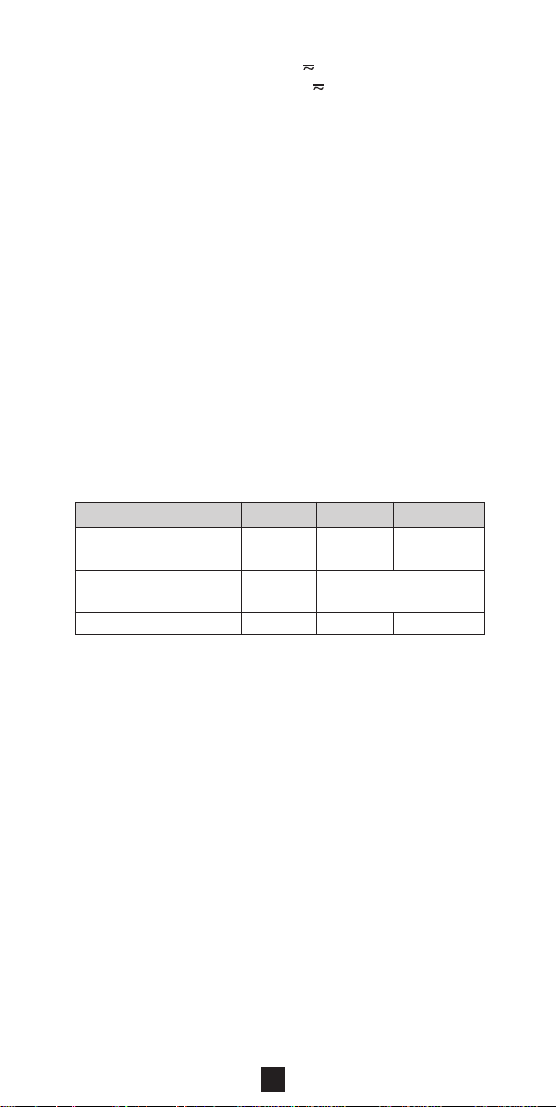
Function Inter nal temperature External temperature
Type of sensor Integrated circuit K couple
Display range 400°C 400°C 4,000°C
Measuring +50.0°C +399.9°C +1,000°C
range +15.0°F to -50.0°F to +400°F to
Accuracy ± 1.5°C 1% L ±1.5°C 1% L ±1.5°C
Resolution 0.1°C 1°C
Detection of INT symbol lit
sensor cutoff
Thermal time
constant
Note: The accuracy stated for external temperature
measurement does not take the accuracy of the K couple
into account.
■ MIN/ MAX Mode:
- Accuracy: ditto preceding table + 0.2% L
- Capture time: 100 ms typ. (every 800 ms)
400°F 400°F 4000°F
-10.0°C to -50.0°C to +400°C to
+120.0°F +399.9°F +1832°C
±2.7°F 1% L ±2.7°F 1% L ±2.7°F
0.2°F 1°F
-
0.7 min./°C According to the sensor model
instead of EXT
3.8 Secondary functions
3.8.1 Blocking the display
A short press on the HOLD key freezes the display.
The display is cleared when the key is pressed f or the second
time.
31

3.8.2 Preselection of MIN/MAX mode
MIN/MAX mode is preselected by a short press on the HOLD
key and then on the MIN/MAX key. MIN/MAX mode is then
activated by pressing on the HOLD key.
This function allows MIN/MAX mode to be selected when
required, to avoid for example, the inclusion of untimely or
erroneous MIN/MAX values
3.8.3 Automatic offset of lead resistance
To offset lead resistance, hold the HOLD key down when the
continuity test or resistance measurement function is selected.
When the key is released, once zero is displayed, the
correction value is saved in the clamp.
If the value measured is over 2
and the value of the correction saved is reset to zero.
This correction is inhibited in MIN/MAX mode.
3.8.4 Automatic zero offset when measuring current
To offset the zero, hold the HOLD key down when current
measurement function is selected.
ΩΩ
Ω, this correction is inhibited
ΩΩ
When the key is released, once zero is displayed, the
correction value is saved in the clamp.
If the value measured is over 6 A, this correction is inhibited
and the value of the correction saved is reset to zero.
This correction is inhibited in MIN/MAX mode.
3.8.5 Manual selection of AC or DC mode
The clamp defaults automatically to AC or DC mode (AC or
DC symbol flashes) for V and A functions.
A series of short presses on the yellow key allows alternating
(AC) and continuous (DC) measurement to be selected
manually and to return to automatic mode.
When the mode is selected manually, the AC or DC symbol
is continuous.
It is impossible to select manual mode in MIN/MAX or HOLD
modes.
3.8.6 Selections possible in the continuity function
By default, the clamp is set to the continuity function ( ) for
the corresponding position of the switch.
With a series of presses on the yellow key, the user can select
resistance measurement (Ω) then the semi-conductor test
function ( ) and then return to the continuity function ( ).
3.8.7 Choice of units (°C or °F) when measuring
temperature
The unit can be chosen from the temperature function by a
short press on the yellow key, which allows °C or °F to be
selected as required. The unit is not sa ved when the clamp is
turned off. See § 3.8.8 to save the unit to memory.
32

3.8.8 Saving the unit (°C or °F) when measuring
temperature
Hold the yellow key down and turn the selector switch from
the OFF to the T° position.
The instrument buzzes twice, then the T° symbol lights up
and the °F symbol flashes if the instrument was previously in
°C or the °C symbol flashes if it was in °F.
The configuration chosen is saved when the key is released:
the °F or °C symbol remains lit continuously.
3.8.9 Deactivation of automatic shutdown
Hold the HOLD key down and turn the selector switch from
the OFF position to the position.
The instrument buzzes twice then the P symbol flashes.
The configuration chosen is saved when the key is released:
the P symbol remains lit continuously.
The instrument returns to automatic shutdown mode when
the switch is placed in the OFF position.
3.8.10 Activation of the V-Live function
Hold the HOLD key down and turn the selector switch from
the OFF position to the V position.
The instrument buzzes twice then the V and symbols start
to flash.
The configuration chosen is saved when the key is released:
the V symbol then remains continuously lit and the symbol
flashes.
Follow the same procedure to deactivate the V-Live function:
the symbol is no longer lit when the key is released.
3.8.11 Modification of the buzzer threshold indication
for continuity tests.
Hold the yellow key down and turn the selector switch from
the OFF to the position.
The instrument buzzes once, the Ω and symbols and the
threshold value light up (default value 40.0).
It can then be set between 1 Ω and 40 Ω by a series of presses
on the yellow key (short press: in increments of 1 Ω; key held
down: in increments of 10 Ω).
Once the value is chosen, activate the selector s witch to save .
3.8.12 Setting the instrument’s default parameters.
Hold the yellow key down and turn the selector switch from
the OFF to the A position.
The instrument buzzes twice then all the segments of the
digital display and the symbol flash.
The default settings are saved when the key is released: the
display stops flashing and the symbol disappears.
33

The default settings are:
- Buzzer threshold: 40 Ω
- Auto shutdown: with
- V-Live function: none
- Temperature measurement unit: not managed
3.8.13 Date of the instrument’s last calibration.
Hold the MIN/MAX key down and turn the selector switch
from the OFF position to the V position.
The instrument buzzes, then the instrument’s calibration date
is displayed in the form “week - year” (WW.YY) as long as the
MIN/MAX key is held down.
3.8.14 Display of the internal software version.
Hold the HOLD key down and turn the selector switch from
the OFF position to position A.
The instrument buzzes and the software version is displayed
in the format UX.XX for two seconds, then replaced by a
display of all the display’s segments while the HOLD key is
held down.
3.8.15 Display of the display’s segments
See § 3.8.1.4. It is also possible f or all key-s witch combinations
not previously described.
4. GENERAL SPECIFICATIONS
4.1 Dimensions and weight
■ 70 x 193 x 37 mm ■ 260 g
4.2 Instrument’s clamping capacity
■ ≤ 26 mm
4.3 Power supply
■ A standard alkaline 9 V battery (type IEC 6LF22, 6LR61 or
NEDA 1604)
■ Average battery charge life: 75 hrs or 25000 x 10 sec
measures
■ Battery charge indicator
Flashing: autonomy < 1 hr
Continuous: change battery
■ Automatic shutdown if the selector switch or keys are not
activated for 10 minutes (move the selector switch through
the OFF position or activate any key to switch on again)
34
+
-
:

4.4 Environmental parameters
■■
■ Temperature - Humidity
■■
90
80
70
60
50
40
30
Relative humidity in % RH
20
10
0
-50
➂
-40 -30 -20 -10 0 10 20 30 40 50 60 70 80 90
Temperaturein °C
➁
➀
➂
① Reference range ② Operating range
③ Storage range (without battery)
■■
■ Altitude
■■
- Operation: ≤ 2,000 m
- Storage ≤ 12.000 m
■■
■ Indoor use
■■
Impermeability: protection index IP 40
(according to EN
60529, ed. 92)
4.5 Compliance with norms
■■
■ Electrical safety
■■
(as per EN 61010-1 ed. 95 and 61010-2-032, ed. 93)
- Double insulation:
- Installation categor y: III
- Pollution level: 2
- Rated voltage: 600 V (RMS or DC)
■■
■ Electric shocks
■■
- 6 kV in differential mode on the voltmeter function, aptitude
criterion B
- 2 kV on the current measurement cable, aptitude criterion B
■■
■ Electromagnetic compatibility
■■
(as per EN 61326-1 ed. 97 + A1)
Emission: class B
Immunity:
- Electrostatic discharge:
4 kV on contact, aptitude criterion B
8 kV in the air, aptitude criterion B
- Radiation fields: 10 V per m, aptitude criterion A
- Rapid transients: 1 kV, aptitude criterion B
- Directed disturbance: 3 V, aptitude criterion A
■■
■ Mechanical resistance
■■
- Free fall 1 m
- Impact: 0.5 J (test as per IEC 68-2-27)
- Vibration: 0.75 mm (test as per IEC 68-2-6)
■■
■ Auto-extinction (as per UL94)
■■
- Casing: V0
- Jaws: V0
- Display window: V2
(test as per IEC 1000-4-5)
(test as per IEC 68-2-32)
35

4.6 Variations in operating range
Relevant Meas. range Parameter Effect
parameter parameter affected Typical Max
Battery voltage 7.5 to 10 V 1 count ≤ 1 ct 0.2% L +1 ct
Temperature 0...50°C V 0,05% L/10°C 0,2% L /10°C +2 ct
Relative
humidity
Frequency
Position of the Any
conductor position on
in the internal A 0,7% L 1% L +1 count
jaws perimeter of the
(f ≤ 400 Hz) jaws
10....90% RH
40 Hz...1 kHz 1% L +1 ct
1 kHz...5 kHz
40 Hz...400 Hz
400 Hz...1 kHz 5% L +1 ct
1 kHz...5 kHz 3 dB
Remanence 0...600 A peak A 2 mA/A 3 mA/A
Adjacent Conductor
conductor with in contact with
400 A
DC or RMS the external A 45 dB 40 dB
current perimeter of the
running through jaws
Conductor 0...400 V DC V < 1 ct 1 ct
clamped or RMS T° < 1 ct 1 ct
Application
of voltage
to the clamp
Peak
factor
Rejection of
series mode
in DC
Rejection of
series mode
in AC
Rejection of
common mode A < 1 ct 0,1 A
Influence of
an external 0...400 A/m
magnetic (50 Hz)
field
Number of
jaw
opening
manœuvres
0...600 V DC
or RMS
1.4 to 3.5 limited
to 600 A peak
900 V peak
0...600 V/50 Hz V
0...400 A/50 Hz ADC 50 dB 45 dB
0...600 V DC V
0...400 A DC AAC 55 dB 40 dB
0...600 V/50 Hz
50000 A 0.3% L 1% +1 count
A 0,1% L/10°C 0,2% L /10°C +2 ct
Ω
0,1% L/10°C 0,2% L /10°C +2 ct
T° - 0,5% L /10°C +5 ct
V ≤ 1 ct 0,1% L +1 ct
A 0,2% L 0,3% L +2 ct
Ω
T° ≤ 1 ct 0,1% L +1 ct
V see cur ve
A see cur ve
≤ 1 ct
0,3% L +2 ct
6% L +1 ct
1% L +1 ct
A < 1 ct 1 ct
AC 1% L 3% L + 1 count
A
V
AC 1% L 3% L + 1 count
DC 50 dB 45 dB
AC < 1 ct 60 dB
V < 1 ct 60 dB
A 65 dB 60 dB
36

■■
■ Typical frequency response curve
■■
- V = f (f)
2%
0%
-2%
-4%
-6%
Error measurement (%)
-8%
-10%
10 Hz
100 Hz
Specified limits
1000 Hz
Frequency (Hz)
- I = f (f)
30%
25%
20%
15%
10%
5%
Error measurement (%)
0%
5%
10 Hz
100 Hz
Specified limits
Frequency (Hz)
1000 Hz
4.7 Operating limit conditions
■■
■ Temperature of the conductor clamped: ≤ 110°C
■■
10000 Hz
10000 Hz
37

5. T O ORDER
Use the descriptions and references given below:
F03 .................................................................P01. 1209.03Z
Comes in a blister with a set of two touch leads, 1 x K
thermocouple adaptor, 1 x 9 V battery, a carrying case and
these operating instructions.
Accessories and spare parts
■ Set of 2
touch leads (NF EN 61010) ......................... P01. 2950.84
■ Set of 2 leads
with safety plugs (NF EN 61010) ................. P01. 2950.88
■ Set of two alligator clamps (NF EN 61010) . P01. 1018.48
■ Set of 2
IP2X touch leads .......................................... P01. 2951.57
■ Carrying case N°7 ........................................ P01. 2985.32
■ K couple adaptor / Ø 4 mm plugs ................ P01. 1017.80
■ General purpose temperature sensor
SK13 type with handle ................................. P03. 6529.18
■ A number of other K couple type sensors are available to
suit the particular application (ambient air, surface,
penetration, etc.) Please consult us
■ Different measuring accessories broaden the application
scope of your clamp or give it additional functions.
Please consult us
NB: Always use the appropriate accessories for the voltage
and surge category of the circuit to be measured (as
per NF EN 61010).
6. WARRANTY
Our guarantee is applicable for twelve months after the date
on which the equipment is made available (extract from our
General Conditions of Sale, available on request).
38

7. MAINTENANCE
For maintenance, use only specified spare parts. The
manufacturer will not be held responsible for any accident
occuring following a repair done other than by its After
Sales Service or approved repairers.
7.1 Changing the battery
The clamp must be disconnected from any external
source of electricity and must not encircle a cable.
■ Put the switch into the OFF position
■ Slide a screwdriver into the slot at the top of the battery
flap (at the back of the clamp) and push the battery flap
upwards.
■ Replace the dead battery with a 9 V battery, type LF22,
ensuring that the polarity is respected.
■ Replace the battery in its housing, then replace the battery
flap.
7.2 Storage
If the clamp is not to be used for a period of more than 60
days, remove the batteries and store them separately.
7.3 Cleaning
The clamp must be disconnected from any external
source of electricity and must not encircle a cable.
■ T o clean the casing and jaws, use a cloth slightly moistened
with soapy water. Clean off with a damp cloth. Then dry
quickly with a cloth or pulsed air.
■ Do not splash water onto the clamp.
■ Ensure that the space between the jaws is kept perfectly
clean.
7.4 Metrological verification
It is essential that all measuring instruments are regularly
calibrated.
For checking and calibration of your instrument, please contact
our accredited laboratories (list on request) or the Chauvin
Arnoux subsidiary or Agent in your countr y.
Maintenance
Repairs under or out of guarantee: please return the product
to your distributor.
39
 Loading...