

Page 1

■■
■ PINCE AMPEREMETRIQUE AC/DC
■■
■■
■ AC/DC CURRENT CLAMP
■■
E3N
FRANCAIS
ENGLISH
Mode d'Emploi
User's Manual
1
Page 2

Vous venez d’acquérir une pince et nous vous remercions de votre confiance.
Pour obtenir le meilleur service de votre appareil :
■ lisez attentivement ce mode d’emploi
■ respectez les précautions d’emploi
Significations du symbole :
Attention ! Consulter le mode d’emploi avant d’utiliser l’appareil.
Dans le présent mode d’emploi, les instructions précédées de ce symbole, si elles ne sont
pas bien respectées ou réalisées, peuvent occasionner un accident corporel ou
endommager l’appareil et les installations.
GARANTIE
Notre garantie s’exerce, sauf stipulation expresse, pendant douze mois après la date
de mise à disposition du matériel (extrait de nos Conditions Générales de Vente,
communiquées sur demande).
PRECAUTIONS D'EMPLOI
■ Ne pas utiliser la pince sur des conducteurs dont le potentiel est supérieur à 600V eff.
■ Veiller à la propreté des entrefers. Les nettoyer si nécessaire avec un chiffon doux légè-
rement huilé afin d'éviter l'oxydation.
■ Bien maintenir centré le câble ou la barre dans la pince et celle-ci bien perpendiculaire
au conducteur.
■ Eviter la proximité d'autres conducteurs qui pourrait créer des champs parasites.
■ La pince doit être totalement déconnectée et sur la position "OFF" pour opérer au
changement de la pile.
■ Pour votre sécurité, assurez-vous que l'appareils utilisés avec la pince sont également
conformes à la norme IEC 1010.
POUR COMMANDER
Réf.
Pince E3N ................................................................................................................................................................. 1200.43A
livrée avec une pile 9V et un mode d'emploi
Rechange :
Pile 9V alcaline ...................................................................................................................................................... 1006.20
2
Page 3

ENGLISH .................................................................................................. 11
SOMMAIRE
Page
Présentation ......................................................................................................................................................................... 3
Description ............................................................................................................................................................................. 4
Caractéristiques électriques ..................................................................................................................................... 4
Sécurités électriques ...................................................................................................................................................... 7
Caractéristiques mécaniques .................................................................................................................................. 8
Caractéristiques générales ........................................................................................................................................ 8
Mode opératoires .............................................................................................................................................................. 9
Maintenance ......................................................................................................................................................................... 10
Annexe (courbes de réponse) ................................................................................................................................. 19
PRESENTATION
La pince E3N est une sonde de courant pour oscilloscope utilisant une cellule à effet Hall
permettant la mesure de courant continu ou alternatif sans intervention sur l'installation (sans
ouvrir le circuit).
Elle peut mesurer des courants de 50 m A à 100 A crête.
Elle dispose de 2 calibres et 2 voyants indiquant :
- une alimentation correcte de la pince, "ON",
- le dépassement du calibre utilisé (saturation ou écrêtage), "OL".
De plus une molette permet de réaliser le zéro afin de s'adapter au mieux à l'environnement
de mesure.
Cette pince s'adapte sur tous les appareils de mesure ayant une entrée BNC et une
impédance de 1MΩ, < 100pF.
3
Page 4

DESCRIPTION
Commutateur
Le commutateur comporte 3 positions :
- Arrêt : la pince n'est plus alimentée.
- Calibre 10mV/A : mesure des courants crête continus ou alternatifs sur la base de 10mV
par Ampère.
- Calibre 100mV/A : mesure des courants crête continus ou alternatifs sur la base de 100mV
par Ampère. Ce calibre augmente la sensibilité de la pince tout en diminuant l'étendue
de mesure.
Témoin de pile
Cette LED est éteinte quand le commutateur est sur "arrêt". En utilisation normale, la LED
verte est allumée. Quand le commutateur n'est plus sur arrêt et que la LED est éteinte, celleci prévient que la valeur de la tension pile est trop faible ou que la cellule n'est plus alimentée,
décelant ainsi un défaut de la pince.
Réglage du "zéro" de la pince
La molette permet de réaliser la mise à zéro de la tension de sortie. Il est ainsi possible de
s'affranchir des différentes erreurs dues aux dérives thermiques, au champ magnétiques
terrestre, à l'environnement, et à la rémanence.
Témoin de dépassement de calibre
Ce témoin symbolisé par "OL" s'allume en rouge lorsque le signal à mesurer est supérieur
aux possibilités du calibre. Il peut indiquer également la présence d'une impulsion supérieure
aux possibilités de mesure du calibre ou que la mesure faite sur la pince n'est pas valide.
Trappe à pile
Pour procéder au changement de la pile 9V, la pince doit être en position normale (machoires
fermées) et déconnectée de l'oscilloscope; elle ne doit pas enserrer de conducteur et le
commutateur doit être sur la position "OFF". Dévisser la vis imperdable puis tirer la trappe
dans le prolongement de la poignée pour accéder à la pile à changer.
CARACTERISTIQUES ELECTRIQUES
Calibre Etendue de mesure Erreur intrinsèque
Cal 100mV/A 50mA à 10A crête 3% L + 50mA
Cal 10mV/A 50mA à 40A crête 4% L + 50mA
Cal 10mV/A 40A à 100A crête Voir courbe ci-après
L: de la lecture
4
Page 5

Linéarité pour un signal continu (Calibre 10mV/A)
10
0
-1
Incertitude en %
-5
-10
20
4030
1009080706050
I(A)
▼
Niveau typique de bruit en sortie (valeur crête crête)
Bande de fréquence DC-100kHz
Calibre 10mV/A 480µV
Calibre 100mV/A 3mV
n Ces précisions sont données pour une température ambiante de 23° ± 3°C, humidité
20 à 75% HR, fréquence DC à 1kHz, impédance de charge: 1 MW/100pF, conducteur
centré et parallèle au repère.
n Bande passante: DC à 100 kHz.
La bande passante de l'oscilloscope associé dépend de la fréquence du signal à mesurer.
Une bande passante supérieure à quatre fois la fréquence du signal à mesurer est
suffisante.
n Fréquence d'utilisation (n'entraînant pas une erreur supplémentaire de plus de 3% par
rapport au domaine de référence): DC à 20 kHz.
n Fréquence de coupure: - 3db à 100kHz.
n Temps de montée ou descente: <4µs.
GRANDEURS D'ENTREE/SORTIE
- Niveau typique de bruit en sortie (valeur crête crête) relevé avec un oscilloscope tektronix
7603 tiroir 7A22 (BP: 100kHz).
Bande de fréquence DC-100kHz
Calibre 10mV/A 480µV
Calibre 100mV/A 3mV
5
Page 6

- Décalage du zéro: 1 A max.
La molette de "zéro" permet de corriger grossièrement ce décalage. Le réglage du "zéro"
de l'appareil de mesure permet d'obtenir un réglage plus fin.
Nota: Il est conseillé de vérifier le décalage du zéro après avoir mesuré un courant de
forte intensité. Pour cela, repérer une référence sur l'oscilloscope en position GND, puis
se coupler en DC, si un décalage trop important est présent, cela signifie que la pince
est magnétisée.
Pour démagnétiser la pince, il suffit d'ouvrir et de fermer la pince plusieurs fois hors du
conducteur ou d'appliquer sur celle-ci un champ magnétique décroissant.
GRANDEURS D'INFLUENCES
- Tension pile de 6,5V à 10V: ± 6 mA/V typique, ± 10 mA/V max.
- Température de 0 à 50°C: ± 2000 ppm/°C max.
- Position du conducteur dans la fenêtre ( signal AC de fréquence 1kHz) :
max ± 0,5% de la lecture .
- Champ magnétique extérieur généré par un courant AC ou DC de 1A circulant dans un
conducteur placé à proximité immédiate (voir courbe typique ci-après).
- Les erreurs de linéarité, précision, dérive en température et autres caractéristiques de
l'oscilloscope sont à prendre en compte lors d'une mesure.
10
Atténuation en dB
0
-5
-10
-20
-30
-40
100 1000 10 000
Conducteur parallèle
à la pince
Conducteur perpendiculaire
Immunité vis à vis d'un conducteur extérieur
placé contre le boîtier de la pince
100 000
Fréquence en Hz
à la pince
6
Page 7

SECURITES ELECTRIQUES
PROTECTION CONTRE LES CHOCS ELECTRIQUES
Appareil à isolation double ou isolation renforcée dans la partie préhensible en utilisation
normale, et à isolation simple ou isolation supplémentaire entre le primaire et la sortie
secondaire.
Tension de service maximale suivant CEI 1010 :
600V dans les installations de catégorie III et degré de pollution 2.
300V dans les installations de catégorie IV et degré de pollution 2.
Tension d'épreuve diélectrique suivant CEI 1010 :
5550V 50/60Hz entre les parties préhensibles en utilisation normale d'une part, et le primaire
avec le secondaire d'autre part.
3250V 50/60Hz entre le primaire d'une part, et le secondaire d'autre part.
COMPATIBILITE ELECTROMAGNETIQUE
Décharge électrostatique : 4kV sans perturbation
8kV sans destruction suivant CEI 801-2.
Champ rayonné : 3V/m suivant CEI 801-3.
Transitoires rapides : 1kV classe 1 sans perturbation
2kV classe 2 avec défauts mineurs suivant CEI 801-4.
Chocs électriques : 1kV - 0,5kA classe 2 sans perturbation.
2kV - 1kA classe 3 avec défauts mineurs suivant CEI 801-5.
LIMITE DU COURANT CRETE NON DESTRUCTIF EN FONCTION DE LA FREQUENCE
Ip (A crête)
140
100
50
0
10
100
7
1000
10000
F(Hz)
Page 8

CARACTERISTIQUES MECANIQUES
Dimensions max. du conducteur:
∅ 11,8mm.
Ouverture des mâchoires :
29
12,5mm maximum.
Dimensions : 231x67x36mm.
Cordon bifilaire (coaxial) de 2m
231
terminé par une prise BNC isolée
et surmoulée.
Masse : 330g avec la pile.
21
PROTECTIONS
Degrés de protection: IP 20 selon CEI 529.
Protection contre les chocs: 100G, 6 ms, demi-période, suivant CEI 68-2-27
Hauteur de chute sous tous les angles: 1m.
Tenue aux vibrations: 10/55/10 Hz 0,15mm, suivant CEI 68-2-6.
Secousses: 40 G, 6ms, 4000 secousses, suivant CEI 68-2-29.
CARACTERISTIQUES GENERALES
Conditions d'environnement
1 Domaine de référence
100
90
2 Domaine d'utilisation
3 Domaine de stockage
67
Cotes
en mm
36
80
70
60
50
Humidité en % de HR
40
30
20
10
0
-50° -10° 10° 30° 50° 70° 90°
-30°
3 2 21 3
8
Température en C°
Page 9

Pile : alcaline 9V type 6 LR 61
Consommation : 8,6 mA typique, 12mA max
Autonomie : 55h typique, 40h mini
Témoin : extinction du témoin lumineux vert pour une tension de pile <6,5V
Classe de protection : classe II selon CEI 348
Tenue diélectrique : 4kV
Courant de fuite : <0,5mA
MODE OPERATOIRE
■ Pour réaliser une mesure de courant, mettre en fonctionnement la pince en choisissant
le calibre 100mV/A. Vérifier que le témoin de pile "ON" (vert) est allumé et que le témoin
"OL" est éteint.
■ Raccorder la pince à l'oscilloscope. Pince fermée et n'enserrant pas de conducteur,
sélectionner la sensibilité la plus forte (par exemple 1mV/cm) sur l'oscilloscope et
100mV/A sur la pince, puis régler le "zéro" de la pince avec la molette par rapport à
une référence choisie sur l'oscilloscope. Le zéro de l'oscilloscope permet d'ajuster
ce réglage.
■ Sélectionner les sensibilités de mesure de la pince et de l'oscilloscope.
■ Choisir le couplage le mieux adapté à la mesure sur l'oscilloscope.
■ Repérer le sens du courant primaire grâce à la flèche dessinée sur et sous le boîtier.
■ Insérer le conducteur parcouru par l'intensité à mesurer la pince et effectuer la mesure.
■ Au besoin, revérifier l'origine de la trace, mâchoires hors du conducteur et refaire la
mesure.
9
Page 10
MAINTENANCE
Pour la maintenance, utilisez seulement les pièces de rechange qui ont été spé-
cifiées. Le fabricant ne pourra être tenu pour responsable de tout accident
survenu suite à une réparation effectuée en dehors de son service après-vente ou des
réparateurs agréés.
n Entrefer: Il est nécessaire de toujours maintenir les entrefers de la pince propres.
Pour cela veiller à les nettoyer et les huiler légèrement pour éviter l'oxydation.
Ne pas laisser la pince dans des lieux très humides, ou exposés à des chutes d'eau.
n Poignées et boîtier: Nettoyer avec un chiffon ou une éponge humide imbibée d'eau
savonneuse, rincer de la même façon sans jamais faire couler d'eau sur la pince. Sécher
avec un chiffon ou de l'air pulsé.
n Pour permettre de tenir les performances de la pince, il est conseillé de procéder à une
vérification ou réétalonnage tous les ans.
VÉRIFICATION MÉTROLOGIQUE
Comme tous les appareils de mesure ou d’essais, une vérification périodique
est nécessaire.
Pour les vérifications et étalonnages de vos appareils, adressez-vous à nos laboratoires de
métrologie accrédités COFRAC ou aux agences Manumesure.
Renseignements et coordonnées sur demande : Tél. : 02 31 64 51 43 Fax : 02 31 64 51 09
Réparation sous garantie et hors garantie.
Adressez vos appareils à l’une des agences régionales MANUMESURE, agréées CHAUVIN
ARNOUX
Renseignements et coordonnées sur demande : Tél. : 02 31 64 51 43 Fax : 02 31 64 51 09
Réparation hors de France métropolitaine.
Pour toute intervention sous garantie ou hors garantie, retournez l’appareil à votre distributeur.
10
Page 11

ENGLISH
Thank you for purchasing a clamp. To get the best service from this instrument:
■ read this user’s manual carefully
■ respect the safety precautions detailed
Meaning of the symbol :
Warning ! Please refer to the User’s Manual before using the instrument.
In this User’s Manual, the instructions preceded by the above symbol, should they not
be carried out as shown, can result in a physical accident or damage the instrument and
the installations.
WARRANTY
Our guarantee is applicable for twelve months after the date on which the equipment
s made available (extract from our General Conditions of Sale, available on request).
SAFETY PRECAUTIONS
■ Do not use the clamp on conductors in which the voltage is more than 600 V rms.
■ Keep the jaw faces clean. Clean them if necessary with a lightly oiled soft cloth to prevent
rusting.
■ Keep the cable or the busbar centred in the clamp which should be perpen-dicular to the
conductor.
■ Avoid proximity to other conductors which may create fields of interference.
■ The clamp must be totally disconnected in the OFF position when the battery is changed.
■ For your safety, ensure that the instruments used with your clamp are also in accordance
with IEC 1010.
TO ORDER
Ref
Clamp E3N .............................................................................................................................................................. 1200.43A
supplied with a 9V battery and an Operator's Manual
Spares:
9V alkaline battery ............................................................................................................................................. 1006.20
11
Page 12

SUMMARY
Page
Presentation ......................................................................................................................................................................... 12
Description ............................................................................................................................................................................ 12
Electrical specifications ................................................................................................................................................ 13
Electrical safety .................................................................................................................................................................. 15
Mechanical specifications ........................................................................................................................................... 16
General specifications .................................................................................................................................................. 17
Operating mode ................................................................................................................................................................ 17
Maintenance ........................................................................................................................................................................ 18
Appendices (response graph) ................................................................................................................................. 19
PRESENTATION
The E3N clamp is a current probe for oscilloscope which uses a Hall effect cell for the
measurement of DC or AC current without modification of the installation (without switching
off the circuit)
It can measure currents from 50 mA to 100 A peak.
It has 2 ranges and 2 lights indicating:
- "ON", correct power supply to the clamp,
- "OL", overload of the range in use (saturation or peak).
In addition a thumbwheel can be used to reset zero for adaptation to the measu-rement
environment.
This clamp adapts to all measurement instruments which have a BNC input and an impedance
of 1MΩ, < 100 pF.
DESCRIPTION
Switch
The switch has 3 positions:
- Off: The clamp is no longer supplied with power
- Range 10 mV/A: measurement of DC or AC peak currents on the basis of 10 mV per
ampere.
- Range 100 mV/A: measurement of DC or AC peak currents on the basis of 100 mV per
ampere.
This range increases the sensitivity of the clamp whilst reducing the measurement extent.
12
Page 13

Battery indicator
This LED is unlit when the switch is OFF.
In normal use, the green LED is lit. When the switch is no longer in the OFF position and the
LED is unlit, this warns that the value of the battery voltage is too low or that the cell is no longer
supplied with power, thus showing that there is a fault in the clamp.
Resetting zero on the clamp
The thumbwheel makes it possible to reset the output voltage to zero. It is thus possible to
overcome the different errors due to thermal shifts, the Earth’s magnetic field, the environment,
and residual induction.
Indicator of range overload
This indicator symbolised by «OL» shows as a red light when the measurement signal is
outside the capabilities of the range. It can also indicate the presence of an impulse outside
the capabilities of the range or that the measurement made on the clamp isn’t valid.
Battery compartment
To change the 9V battery, the clamp should be in the normal position (jaws closed) and
disconnected from the oscilloscope, it must not clamp any conductor and the switch must be
in the «OFF» position. Unscrew the tool release screw then pull off the cover in the handle
extension to access the battery to be changed.
ELECTRICAL SPECIFICATIONS
Range Measurement extent Intrinsic error
Range 100mV/A 50mA to 10A peak 3% R + 50mA
Range 10mV/A 50mA to 40A peak 4% R + 50mA
Range 10mV/A 40A to 100A peak Graph value below
13
R: reading
Page 14
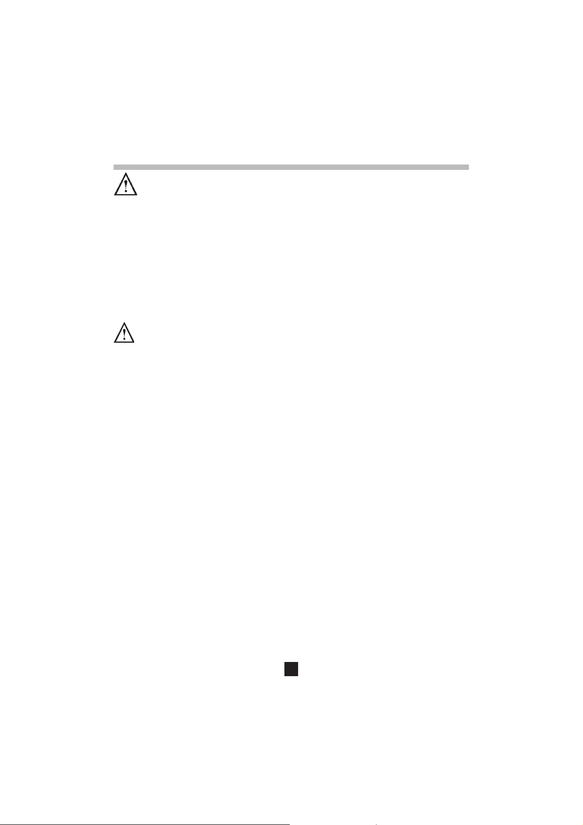
Linearity for a DC signal (Range 10 mV/A)
12345678901234567890123456789012123456789
12345678901234567890123456789012123456789
12345678901234567890123456789012123456789
12345678901234567890123456789012123456789
12345678901234567890123456789012123456789
12345678901234567890123456789012123456789
12345678901234567890123456789012123456789
12345678901234567890123456789012123456789
12345678901234567890123456789012123456789
12345678901234567890123456789012123456789
12345678901234567890123456789012123456789
12345678901234567890123456789012123456789
12345678901234567890123456789012123456789
12345678901234567890123456789012123456789
12345678901234567890123456789012123456789
12345678901234567890123456789012123456789
12345678901234567890123456789012123456789
12345678901234567890123456789012123456789
12345678901234567890123456789012123456789
12345678901234567890123456789012123456789
12345678901234567890123456789012123456789
12345678901234567890123456789012123456789
12345678901234567890123456789012123456789
12345678901234567890123456789012123456789
12345678901234567890123456789012123456789
12345678901234567890123456789012123456789
12345678901234567890123456789012123456789
12345678901234567890123456789012123456789
12345678901234567890123456789012123456789
12345678901234567890123456789012123456789
12345678901234567890123456789012123456789
20
10
0
4030
-1
Uncertainty in %
-5
-10
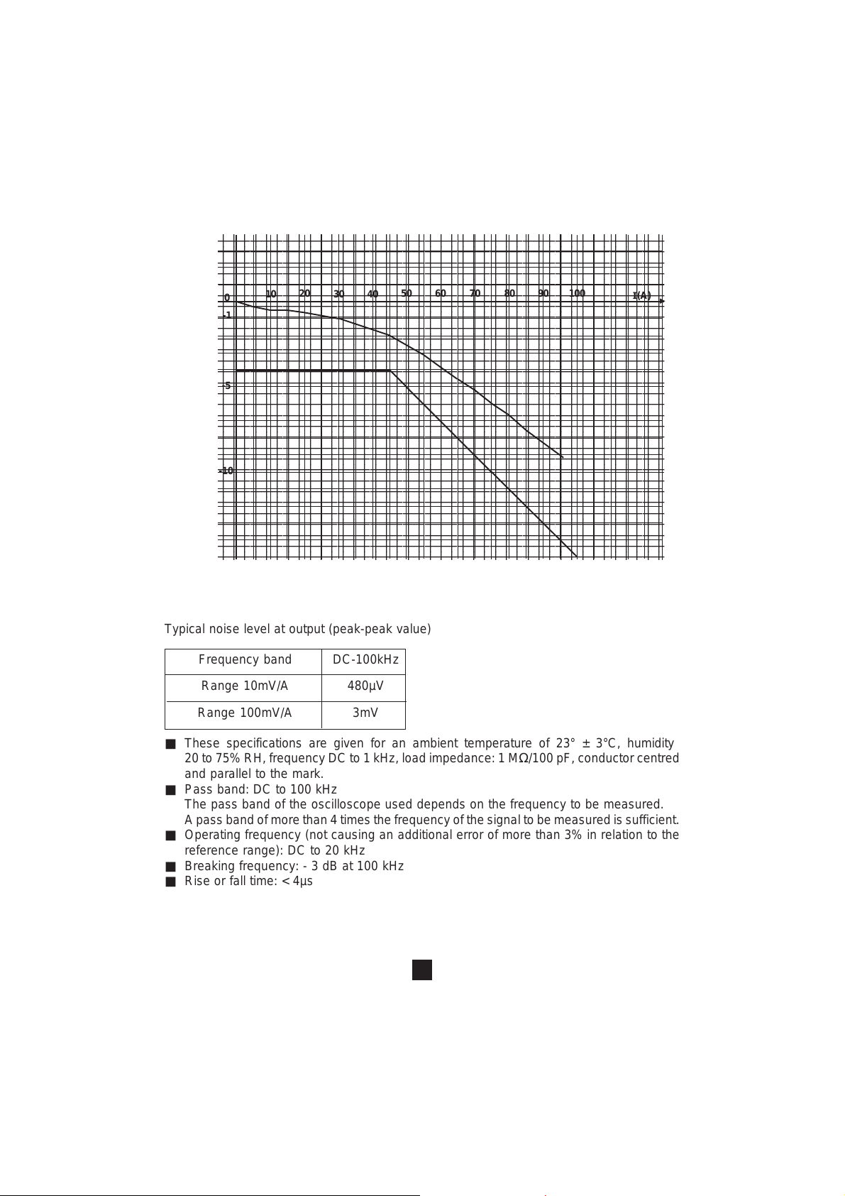
Typical noise level at output (peak-peak value)
Frequency band DC-100kHz
Range 10mV/A 480µV
1009080706050
I(A)
▼
Range 100mV/A 3mV
■ These specifications are given for an ambient temperature of 23° ± 3°C, humidity
20 to 75% RH, frequency DC to 1 kHz, load impedance: 1 MΩ/100 pF, conductor centred
and parallel to the mark.
■ Pass band: DC to 100 kHz
The pass band of the oscilloscope used depends on the frequency to be measured.
A pass band of more than 4 times the frequency of the signal to be measured is sufficient.
■ Operating frequency (not causing an additional error of more than 3% in relation to the
reference range): DC to 20 kHz
■ Breaking frequency: - 3 dB at 100 kHz
■ Rise or fall time: < 4µs
14
Page 15

INPUT/OUTPUT MAGNITUDES
- Typical output noise level (crest to crest value): set with: Oscilloscope Tektronix 7603 drawer
7A22. BP: 100 kHz.
Frequency range DC-100kHz
Range 10mV/A 480µV
Range 100mV/A 3mV
- Zero offset: 1 A max
The zero thumbwheel makes it possible to roughly correct this offset. The zero reset on the
measurement instrument makes it possible to obtain a finer adjustment.
NB: It is advisable to check the zero offset after having measured a high power current. To
do this, mark a reference on the oscilloscope on the GND position, then connect up on DC,
if an offset is present which is too high, this means that the clamp is magnetized.
To demagnetize the clamp, simply open and close the clamp several times without enclosing
a conductor or apply a decreasing magnetic field to it.
DISTORTION MAGNITUDES
- Battery voltage from 6.5 V to 10 V: ± 6 mA/V typical, ± 10 mA/V max
- Temperature from 0 to 50°C: ± 2000 ppm/°C max
-
Position of the conductor in the window (AC signal of frequency 1 kHz): max ± 0.5% of the reading.
- External magnetic fields generated by an AC or DC current of 1A flowing in a conductor
placed in immediate proximity (see graph below).
- Errors of linearity, accuracy, temperature shift and other specifications of the oscilloscope
should be taken into account during measurement.
10
100 1000 10 000
100 000
Attenuation in dB
0
-5
-10
-20
-30
-40
Conductor parrallel
to the clamp
Immunity froman external conductor
against the case of the clamp
15
Frequency in Hz
Conductor perpendicular
to the clamp
Page 16

ELECTRICAL SAFETY
PROTECTION FROM ELECTRIC SHOCKS
Instrument with double insulation or strengthened insulation in the part that is hand held in
normal use, and with single insulation or additional insulation between the primary and the
secondary output.
Maximum service voltage in accordance with IEC 1010 :
600V in installations of category III and degree of pollution 2.
300V in installations of category IV and degree of pollution 2.
Dielectric strength test voltage in accordance with IEC 1010 :
5550V 50/60Hz between the parts that are hand-held in normal use, on one hand, and the
primary with the secondary on the other hand.
3250V 50/60Hz between the primary on one hand, and the secondary on the other hand.
ELECTROMAGNETIC COMPATIBILITY
Electrostatic discharge : 4kV without disturbance
8kV without destruction in accordance with IEC 801-2.
Radiated field : 3V/m in accordance with IEC 801-3
Rapid transients : 1kV class 1 without disturbance
2kV class 2 with minor defects in accordance with IEC 801-4.
Electric shocks : 1kV - 0.5kA class 2 without disturbance
2kV - 1kA class 3 with minor defects in accordance with IEC 801-5.
LIMIT OF THE NON DESTRUCTIVE PEAK CURRENT AS A FUNCTION OF THE FREQUENCY
Ip (A peak)
140
100
50
0
10
100
16
1000
10000
F(Hz)
Page 17

MECHANICAL SPECIFICATIONS
Max. cable dimensions: ∅ 11.8 mm
Jaw opening: 12.5 mm maximum
Dimensions: 231 x 67 x 36 mm
Twin core lead (coaxial) 2m ended by
a BNC plug insulated and moulded
Weight: 330 g with battery
29
231
67
Sizes
in mm
PROTECTIONS:
21
Degrees of protection: IP 20 to IEC 529
Protection from shocks: 100 G, 6 ms, half-cycle, to IEC 68-2-27
Drop height from all angles: 1 m
Resistance to vibrations: 10/55/10 Hz 0.15 mm, to IEC 68-2-6
Bumps: 40 G, 6 ms, 4000 bumps, to IEC 68-2-29
GENERAL SPECIFICATIONS
Environmental conditions
100
90
80
70
60
50
40
Humidity in % RH
30
20
10
0
-50°
-30°
Battery: Alkaline 9V type 6 LR 61
Consumption: 8.6 mA typical, 12 mA max
Service life: 55 h typical, 40 h min.
Indicator: Green light goes out for a battery voltage < 6.5 V
Class of protection: Class II according to IEC 348
Dielectric strength: 4 kV
Leakage current: < 0.5 mA
3 2 1 2 3
-10° 10° 30° 50° 70° 90°
36
1 Reference range
2 Working range
3 Storage range
Temperature in °C
17
Page 18

OPERATING MODE
■ To make a current measurement, switch on the clamp by selecting the 100 mV/A range.
Check that the battery indicator (green) is lit and that the «OL» indicator is not lit.
■ Connect the clamp to the oscilloscope.
With the clamp closed and without clamping a conductor, select the highest sensitivity
(for example 1 mV/cm) on the oscilloscope and 100 mV/A on the clamp, then set zero on
the clamp with the thumbwheel in relation to a reference chosen on the oscilloscope. Zero
on the oscilloscope makes it possible to adjust this setting.
■ Select the measurement sensitivities of the clamp and the oscilloscope.
■ Choose the connection method which is the best adapted to measurement on the
oscilloscope.
■ Note the direction of the primary current by means of the arrow marked on and under
the case.
■ Insert the conductor carrying the current to be measured in the clamp and take the
measurement.
■ If necessary, re-check the origin of the graph, with the jaws not clamped around the
conductor, and make the measurement again.
MAINTENANCE
For maintenance, use only specified spare parts. The manufacturer will not be
held responsible for any accident occurring following a repair done other than
by its After Sales Service or approved repairers.
■ Jaw faces : It is necessary to always keep the jaw faces clean. Clean them and lightly oil
them to avoid rust. Do not leave the clamp in very damp places, or directly exposed to
water.
■ Handles and case : Clean with a cloth or a sponge soaked with soapy water, rinse in the
same way without ever getting water on the clamp. Dry with a cloth or in an air flow.
■ To maintain the performance of the clamp, it is advisable to carry out a check or recali-
bration every year.
CALIBRATION
It is essential that all measuring instruments are regularly calibrated.
For checking and calibration of your instrument, please contact our accredited laboratories
(list on request) or the Chauvin Arnoux subsidiary or Agent in your country.
REPAIRS
Repairs under or out of guarantee: please return the product to your distributor.
18
Page 19

ANNEXE / APPENDICE
Courbes typiques de réponse en fréquence et déphasage
courant de mesure : 1A crête
Typical response curves for frequency and phase shift
measurement current : 1A peak
(gain)
(phase)
0.5dB
0dB
-0.5dB
-1dB
-1.5dB
-2dB
-2.5dB
-3dB
-3.5dB
-4dB
-4.5dB
0.1kHz
1kHz
courant de mesure : 1A crête
measurement current : 1A peak
(gain)
(phase)
50°
10kHz
.
100kHz
.
CAL. / Range : 100 mV/A
CAL. / Range : 10mV/A
1000kHz
fréquence
frequency
CAL. / Range : 100 mV/A
CAL. / Range : 10mV/A
-50°
-100°
-150°
-200°
-250°
0°
0.1kHz
1kHz
10kHz
19
100kHz
1000kHz
fréquence
frequency
Page 20

Différents exemples limites de réponse de la pince
Different limiting examples of the response of the response of the Clamp
F=100Hz I=100mA crête / peak
TR2A:0.20V:1ms
TR1A:10.0V:1ms
F=10kHz I=100mA crête / peak
TR2A:0.20V:10us
TR1A:10.0V:10us
F=100Hz I=2A crête / peak
signal de référence
Reference signal
Pince
Clamp
signal de référence
Reference signal
Pince
Clamp
20
TR2A:05.0V:1ms
TR1A:0.20V:1ms
signal de référence
Reference signal
Pince
Clamp
Page 21

F=10kHz I=1A crête / peak
TR2A:0.5.0V:10us
TR1A:0.20V:10us
F=10kHz I=50mA crête / peak
TR2A:100mV:20us
TR1A:0.5.0V:20us
F=10kHz I=50mA crête / peak
signal de référence
Reference signal
Pince
Clamp
signal de référence
Reference signal
Pince
Clamp
21
TR2A:100mV:20us
TR1A:05.0mV:20us
signal de référence
Reference signal
Pince
Clamp
Page 22

I=2A crête / peak
I=2A crête / peak
I=2A crête / peak
TR2A:05.0V:2ms
TR1A:0.20V:2ms
TR2A:05.0mV:5ms
TR1A:0.20V:5ms
signal de référence
Reference signal
Pince
Clamp
signal de référence
Reference signal
Pince
Clamp
22
TR2A:05.0mV:5ms
TR1A:0.20V:5ms
signal de référence
Reference signal
Pince
Clamp
Page 23

I=2A crête / peak
I=2A crête / peak
I=2A crête / peak
TR2A:05.0V:5ms
TR1A:0.20V:5ms
TR2A:05.0mV:2ms
TR1A:0.20V:2ms
TR2A:05.0mV:5ms
signal de référence
Reference signal
Pince
Clamp
signal de référence
Reference signal
Pince
Clamp
signal de référence
Reference signal
23
TR1A:0.20V:5ms
Pince
Clamp
Page 24

11 - 2006
Code 906 120 289 - Ed. 3
Deutschland - Straßburger Str. 34 - 77694 KEHL /RHEIN - Tél : (07851) 99 26-0 - Fax : (07851) 99 26-60
España - C/ Roger de Flor N°293 - Planta 1 - 08025 BARCELONA - Tél : (93) 459 08 11 - Fax : (93) 459 14 43
Italia - Via Sant’ Ambrogio, 23/25 - 20050 BAREGGIA DI MACHERIO (MI) - Tél : (039) 245 75 45 - Fax : (039) 481 561
Österreich - Slamastrasse 29 / 3 - 1230 WIEN - Tél : (1) 61 61 9 61 - Fax : (1) 61 61 9 61 61
Schweiz - Einsiedlerstrasse 535 - 8810 HORGEN - Tél : (01) 727 75 55 - Fax : (01) 727 75 56
UK - Waldeck House - Waldeck Road - MAIDENHEAD SL6 8BR - Tél : 01628 788 888 - Fax : 01628 628 099
Liban - P.O BOX 60-154 - 1241 2020 Jal el dib- BEYROUT - Tél : +961 1 890 425 - Fax : +961 1 890 424
China - Shanghai Pujiang Enerdis Inst. CO. LTD - 5 F, 3 Rd buildind, n°381 Xiang De Road
200081 - SHANGHAI - Tél : (021) 65 08 15 43 - Fax : (021) 65 21 61 07
USA - d.b.a AEMC Instruments - 200 Foxborough Blvd, Foxborough, MA 02035 - Tél : (508) 698-2115 - Fax : (508) 698-2118
190, rue Championnet - 75876 PARIS Cedex 18 - FRANCE
Tél. (33) 01 44 85 44 85 - Fax (33) 01 46 27 73 89 - http://www.chauvin-arnoux.com
24
 Loading...