

Page 1

BOITES A DECADES
DECADES BOXES
F R A N C A I S
E N G L I S H
Notice de fonctionnement
User’s manual
Page 2

Signification du symbole
ATTENTION ! Consulter la notice de fonctionnement avant d'utiliser
l'appareil. Dans le présent mode d'emploi, les instructions précédées
de ce symbole, si elles ne sont pas bien respectées ou réalisées,
peuvent occasionner un accident corporel ou endommager l'appareil
et les installations.
Signification du symbole
Cet appareil est protégé par une isolation double ou une isolation
renforcée. Il ne nécessite pas de raccordement à la borne de terre de
protection pour assurer la sécurité électrique.
Conformément à la directive WEEE 2002/96/EC
Pour obtenir le meilleur service de votre appareil :
Lisez attentivement cette notice de fonctionnement
Respectez les précautions d‘emploi
2
Page 3

PRECAUTIONS D'EMPLOI
Cet instrument peut-être utilisé sur des installations de catégorie II,
pour des tensions n'excédant pas 150V par rapport à la terre. Les
matériels de catégorie II sont des matériels consommateurs d'énergie,
alimentés à partir de l'installation fixe (cf CEI 664-1, Ed. 92).
CAT II : Les circuits de CAT II sont des circuits d'alimentation d'appareils
domestiques ou analogues, pouvant comporter des surtensions
transitoires de valeur moyenne.
Exemple : alimentation d'appareils ménagers et d'outillage portable.
CAT III : Les circuits de CAT III sont des circuits d'alimentation d'appareils
de puissance pouvant comporter des surtensions transitoires
importantes.
Exemple : alimentation de machines ou d'appareil industriels.
3
Page 4

ENGLISH ................................................................................. see p 16
SOMMAIRE
Présentation générale ............................................................... 5
Boîtes de résistance ................................................................. 6
Boîte de rapport K ..................................................................... 7
Boîtes de capacité .................................................................... 8
Galvanomètre de zéro .............................................................. 9
Boîte double interrupteur ........................................................ 10
Boîte simple inverseur ............................................................ 11
Caractéristiques générales .................................................... 12
Application au pont de Wheatstone ........................................ 13
Rechange et accessoire ........................................................ 13
Maintenance ............................................................................ 14
Garantie ................................................................................... 15
Annexe .................................................................................... 30
4
Page 5

PRESENTATION GENERALE
Ensemble de boîtes pouvant être assemblées mécaniquement et
électriquement les unes aux autres, pour réaliser par exemple,
un pont de Wheatstone.
Elles sont équipées de borne de sécurité Ø 4 mm pour la connectique.
Elles sont livrées avec un cordon de sécurité EN 61010-2-031 (voir
Rechange et Accessoire).
Pour la sécurité d‘utilisation elles sont conformes à la norme
EN 61010-1 (voir Caractéristiques Générales).
Vous reporter aux caractéristiques spécifiques à chaque type de
boîte (voir Sommaire) et aux dessins de description (voir Annexe).
NB : Il y a 8 modèles de boîtes de résistances et 3 modèles de
boîtes de capacités.
5
Page 6

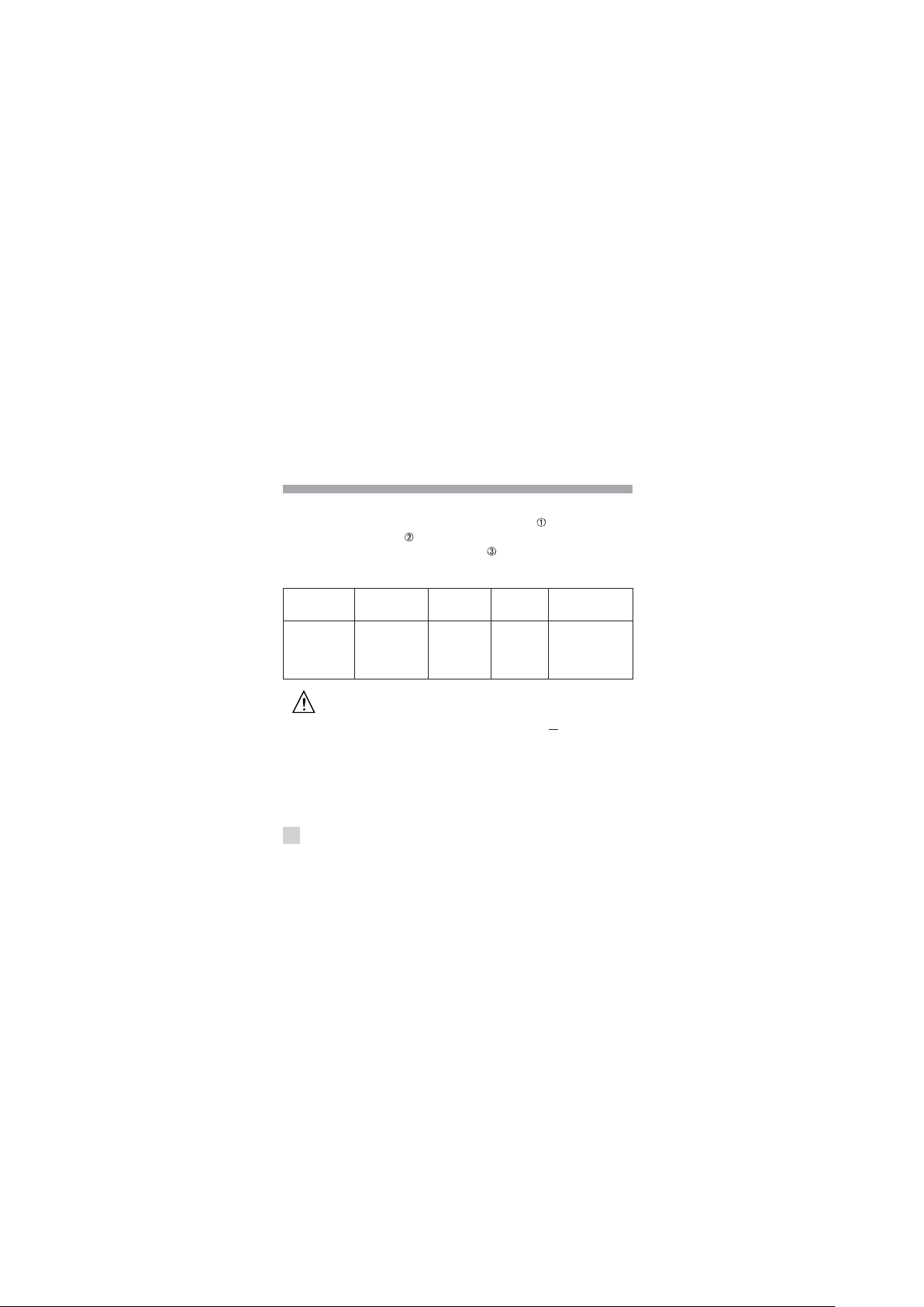
Boîtes de résistance à décade*
Description (voir dessin en ANNEXE)
• Commutateur 11 positions (0 = court circuit)
• Une borne rouge
• Deux bornes noires
Caractéristiques
Bo î te Etendue I maxi U maxi Préc isi on Référence
x 0,1 0,1 à 1 1A 1V 1% ± 5m P03. 19 75.2 1A
x 1 1 à 10 750mA 7, 5V 1% ± 5m P 03. 19 75.2 2A
x 10 10 à 100 250mA 2 5V 0, 5% P 03 .1975.2 3A
x 100 100 à 1000 75m A 75 V 0,5% P0 3 .1 975 .2 4A
x 1000 1 à 10k 25m A 2 50V 0, 5% P03 .1 975 .2 5 A
k x 10 10 à 100k 7,5m A 7 50V 0,5% P0 3.197 5.26 A
k x 100 100 à 1000k 2mA 200 0V 0, 5% P03 .1 975 .2 7A
M x 1 1 à 10M 0,2m A 200 0V 0,5 % P0 3.197 5.28A
• Coefficient de température : ± 50ppm pour les calibres > 1 ,
± 100ppm pour les calibres
• Résiduelle : 15m ± 5m supprimée dès la première valeur
• Dimensions et masse : 72 x 72 x 90mm - 220g
* Livrées avec un cordon EN 61010-2-031
6
≤ 1Ω
Page 7

Boîte de résistance de rapport K*
Réf. P03.1975.31A
Description (voir dessin en ANNEXE)
• Un commutateur avec 7 rapports
- K = 1/1000 - 1/100 - 1/10 - 1 - 10 - 100 - 1000
- Précision : ± 0,2%
- Cœfficient de température : ± 10ppm
• Une borne rouge (connexion à l‘alimentation)
• Deux bornes noires (G connexions au galvanomètre)
- NB : voir le schéma "Application au pont de Wheatstone"
Caractéristiques
I maxi 25mA 75mA 250mA 750mA
K 1 10 100 100 0
• Dimensions et masse : 72 x 72 x 90mm - 220g
* Livrée avec un cordon EN 61010-2-031
7
Page 8

Boîtes de capacité à décade*
Description (voir dessin en ANNEXE)
• Commutateur 11 positions (dont la position 0)
• Deux bornes noires
• Une borne de terre (vert/jaune)
Caractéristiques
Boîte
1µF x 10 1 à 10µF 2 % < 10 -2P03.1996-11A
0,1µF x 10 0,1 à 1µF 2% < 10 -2P03.1996-12A
0,01µF x 10 0,01 à 0,1µF 2 % < 10 -2P03.1996-13A
* Livrées avec un cordon EN 61010-2-031
8
Etendue Précision
• Raccorder la borne de terre à une terre de protection
• avant d‘effectuer une mesure
• Respecter la tension maxi de service 50V... et la tension
de 50V maxi par rapport à la terre
• Après chaque manipulation, décharger la tension
• emmagasinée par le condensateur, dans une résistance
de valeur appropriée
• Dimensions et masse : 72 x 72 x 90mm - 220g
Angle
de perte
Réf érence
Page 9

Galvanomètre de zéro*
Réf. P03.1976-11A
Description (voir dessin en ANNEXE)
• Equipage à suspension par rubans tendus.
• Cadran à miroir antiparallaxe
- Longueur d‘échelle : 20mm
- 10 divisions de part et d‘autre du zéro.
• 2 calibres par bouton-poussoir :
- repos (x1) : ± 1mA soit 100µA/div
- travail (x100) : ± 10µA soit 1µA/div
• Une borne rouge
• Une borne noire
• Vis de réglage du zéro
Caractéristiques
I maxi : 1mA
• Résistance interne : 180 (sur les 2 calibres)
• Précision : ± 2,5% de l'étendue d‘échelle
• Dimensions et masse : 72 x 72 x 63mm - 220g
* Livré avec deux cordons EN 61010-2-031
9
Page 10

Boîte double interrupteur*
Réf. P03.1975-29A
Description (voir dessin en ANNEXE)
• Deux interrupteurs et avec :
- 1 position repos
- 1 position travail
- 1 position travail fugitif (poussoir)
• Quatre bornes noires
Caractéristiques
P maxi : 50VA - I maxi : 5A - U maxi : 250V
• Dimensions et masse : 72 x 72 x 90mm - 220g
* Livrée avec un cordon EN 61010-2-031
10
Page 11

Boîte simple inverseur*
Réf. P03.1975.30A
Description (voir dessin en ANNEXE)
• Un inverseur bipolaire avec :
- 1 position repos
- 1 position travail
- 1 position travail inversée
• Quatre bornes noires
Caractéristiques
P maxi : 50VA - I maxi : 5A - U maxi : 250V
• Dimensions et masse : 72 x 72 x 90mm - 220g
* Livrée avec un cordon EN 61010-2-031
11
Page 12

CARACTERISTIQUES GENERALES
1. Conditions climatiques d‘utilisation
Température : -10°C à + 55°C
Humidité relative : 10% < HR < 95%
2. Conformité aux normes internationales
Degré d‘étanchéité (selon EN 60529 Ed. 92) :
indice de protection IP40
Compatibilité électromagnétique (selon EN 50081-1 Ed. 92 et
EN 50082-2 Ed. 95)
Sécurité électrique (selon EN 61010-1 Ed. 95) :
- Double isolation
- Catégorie d‘installation II - Degré de pollution 2
(1) sauf pour les 3 boîtes de capacité : tension assignée 50V.
12
(1)
- Tension assignée 150V
(1)
Page 13

APPLICATION AU PONT DE WHEATSTONE
BK
R1
G
B2
R2
B2 B1
Bat
R3
X
G = galvanomètre de zéro
BK = boîte de rapport K -
avec K =
R3 = boîtes de résistance
X = résistance à mesurer avec X = K x R3
B1 = boîte simple inverseur
B2 = boîte double interrupteur
Bat = alimentation
R2
R1
RECHANGE ET ACCESSOIRE
1. Rechange
• Cordon de sécurité EN 61010-2-031 Ed. 94 ..... P01.2950.56
Longueur 25cm avec 2 fiches de sécurité
Ø 4mm à reprise arrière
2. Accessoire
• Cavaliers de sécurité (jeu de 10) ....................... P01.1018.92A
Entraxe 19mm - Ø 4mm
Réf.
13
Page 14

MAINTENANCE
Pour la maintenance, utilisez seulement les pièces
pourra être tenu pour responsable de tout accident survenu
suite à une réparation effectuée en dehors de son service
après-vente ou des réparateurs agréés.
1 - Nettoyage
Pour nettoyer le boîtier, utiliser un chiffon légèrement imbibé
d'eau savonneuse. Rincer avec un chiffon humide. Ensuite,
sécher rapidement avec un chiffon ou de l'air pulsé.
2 - Vérification métrologique
Pour cet appareil, nous recommandons au moins une vérification
annuelle. Pour les vérifications et étalonnages de vos appareils,
de rechange qui ont été spécifiées. Le fabricant ne
La boîte à décade doit être déconnectée de toute source
électrique.
Comme tous les appareils de mesure ou d’essais,
une vérification périodique est nécessaire.
14
Page 15

adressez-vous à nos laboratoires de métrologie accrédités par
le COFRAC ou aux agences MANUMESURE.
Renseignements et coordonnées sur demande :
Tél. : 02 31 64 51 43 Fax : 02 31 64 51 09
3 - Réparation sous garantie et hors garantie
Adressez vos appareils à l'une des agences régionales
MANUMESURE, agréées CHAUVIN ARNOUX
Renseignements et coordonnées sur demande :
Tél. : 02 31 64 51 43 Fax : 02 31 64 51 09
4 - Réparation hors de France métropolitaine
Pour toute intervention sous garantie ou hors garantie, retournez
l’appareil à votre distributeur.
GARANTIE
Notre garantie s’exerce, sauf stipulation expresse, pendant douze mois après
la date de mise à disposition du matériel. (Extrait de nos Conditions
Générales de Vente, communiquées sur demande).
15
Page 16

Meaning of the symbol
CAUTION! Read the user’s manual before using the instrument. In
this manual, if the safety instructions prefixed with this symbol are not
observed or followed, this will bring hazardous conditions for the
operator or for the instrument and installation.
Meaning of the symbol
This instrument is protected by a double or reinforced insulation. It is
not necessary to connect it the earth protection terminal to ensure
electrical safety.
Compliant with directive WEEE 2002/96/EC
To obtain the best service from this instrument:
please read the instruction manual carefully,
follow the safety instructions included herein.
16
Page 17

PRECAUTIONS FOR USE
This instrument can be used on category II installations for voltages
which do not exceed 150V in relation to the earth. The equipment
classified in category II is energy-consuming equipment, receiving its
power supply from the fixed installation (cf. IEC 664-1, 1992 edition).
CAT II : The circuits of CAT II are power supply circuits of appliances or
portable equipment with transient overvoltages of an average
level.
Example : appliances and portable equipment.
CAT III : The circuits CAT III are power supply circuits of power equipment
with important transient overvoltages.
Example : fixed installation or industrial equipment.
17
Page 18

TABLE OF CONTENTS
Overview ................................................................................. 17
Resistance boxes ................................................................... 18
K-ratio box ............................................................................... 19
Capacitance box ..................................................................... 20
Zero galvanometer .................................................................. 21
Dual switch box ....................................................................... 22
Single inverter switch box ....................................................... 23
General characteristics .......................................................... 24
Application to a wheastone bridge .......................................... 25
Spare parts and accessories ................................................. 25
Maintenance ............................................................................ 26
Warranty .................................................................................. 27
Appendix .................................................................................. 28
18
Page 19

OVERVIEW
Combination of a set of boxes, both mechanically and electrically,
to obtain, for instance, a Wheatstone bridge.
These boxes are fitted with Ø 4mm safety plugs for output
connections.
They are shipped with a EN 61010-2-031 safety cord (see Spare
parts and Accessories). Operating safety is met through the
compl iance to the EN 61010-1 s tandard (see Gener a l
characteristics).
Please refer to the characteristics of each type of box (see Table
of contents) and to the descriptive diagrams (see Appendix).
NB: There exist 8 models of resistance boxes and 3 models of
capacitance boxes.
19
Page 20

Decade resistance box*
Description (see descriptive diagrams in the APPENDIX)
• a 11-position switch (0 = “short circuit”)
• a red terminal
• two black terminals
Characteristics
Box Range I max U max Accuracy Reference
x 0.1 0.1 to 1 1A 1V 1% ± 5m P03 .19 75 .21 A
x 1 1 to 10 75 0m A 7.5 V 1% ± 5m P 03 .197 5.22A
x 10 10 to 100 250mA 25 V 0. 5% P03 .1975.2 3A
x 100 100 to 1000 75m A 75 V 0.5% P03 .19 75 .24 A
x 1000 1 to 10k 25m A 250 V 0. 5% P03 .197 5.2 5A
k x 10 10 to 100k 7.5mA 75 0V 0. 5% P03. 19 75.2 6A
k x 100100 to 1000k 2 mA 2000V 0 . 5% P03. 19 75.2 7A
M x 1 1 to 10M 0.2 mA 2000V 0 . 5% P03. 19 75.2 8A
• Temperature cœfficient: ± 50ppm for ranges > 1 ,
± 100ppm for
ranges
≤1
• Residual: 15m ± 5m suppressed after the first value
• Dimensions and weight: 72 x 72 x 90mm - 220g
20
Page 21

K ratio resistance box*
Ref. P03.1975.31A
Description (see descriptive diagrams in the APPENDIX)
• A switch with seven ratios
- K = 1/1000 - 1/100 - 1/10 - 1 - 10 - 100 - 1000
- Accuracy: ± 0,2%
- Temperature cœfficient: ± 10ppm
• One red terminal (power supply connection)
• Two black terminals (G galvanonemeter connections)
- NB: see diagram: Application to a wheatstone bridge
Characteristics
Max. current 25mA 75mA 250mA 750mA
K 1 10 100 1000
• Dimensions and weight: 72 x 72 x 90mm - 220g
* Shipped with IEC 1010-2-031 cord
21
Page 22
Decade capacitance box*
Description (see descriptive diagrams in the APPENDIX)
• 11-position switch (including “zero” position)
• Two black terminals
• An earthing terminal (green/yellow)
Characteristics
Box
1µF x 10 1 to 10µF 2 % < 10 -2P03.1996-11A
0.1µF x 10 0.1 to 1µF 2 % < 10 -2P03.1996-12A
0.01µF x 10 0.01 to 0.1µF 2 % < 10 -2P03.1996-13A
• Dimensions and weight: 72 x 72 x 90mm - 220g
* Shipped with EN 61010-2-031 cord
22
Range Accuracy
• Connect the earthing terminal to a protection earth
before performing the measurement
• Observe max. operating voltage 50V ... and max.
voltage from ground 50V
• After each operation, unload the voltage stored in the
capacitor into a proper resistance
Loss
angle
Reference
Page 23

Zero galvanometer*
Réf. P03.1976-11A
Description (see descriptive diagrams in the APPENDIX)
• An unit with taut tape suspension
• Antiparallax mirror scale
- Scale length: 20mm
- 10 divisions either side of zero
• 2 pushbutton-selected ranges :
- pushbutton at rest (x1) : ± 1mA i.e 100µA/div
- pushbutton depressed (x100) : ± 10µA i.e 1µA/div
• A red terminal
• A black terminal
• A zero adjust screw
Characteristics
Max. current: 1mA
• Internal resistance: 180 (on both ranges)
• Accuracy: ± 2.5% of full scale
• Dimensions and weight: 72 x 72 x 63mm - 220g
* Shipped with EN 61010- 2- 031 cord
23
Page 24

Dual switch box*
Ref. P03.1975-29A
Description (see descriptive diagram in the Appendix)
• Two switches and with :
- A rest position
- A depressed position
- A temporarily depressed position (pushbutton)
• Four black terminals
Characteristics
Max. power: 50VA, max. current: 5A, max. voltage: 250V
• Dimensions and weight: 72 x 72 x 90mm - 220g
* Shipped with EN 61010- 2- 031 cord
24
Page 25

Single inverter switch box*
Ref. P03.1975.30A
Description (see descriptive diagram in the Appendix)
• One bipole inverter switch with :
- A rest position
- A depressed position
- An inverted depressed position
• Four black terminals
Characteristics
Max. power: 50VA, max. current: 5A, max. voltage: 250V
• Dimensions and weight: 72 x 72 x 90mm - 220g
* Shipped with EN 61010-2-031 cord
25
Page 26

GENERAL CHARACTERISTICS
1. Environmental conditions
Temperature: -10°C to + 55°C
Relative humidity: 10% < HR < 95%
2. Compliance with international standards
Tightness level (according to EN 60529 Ed. 92 standard):
Protection index IP 40
Electromagnetic compatibility (according to EN 50081-1 Ed. 92
and EN 50082-2 Ed. 95 standards)
Electrical safety (according to EN 61010-1 Ed. 95 standard):
- Double insulation
- Installation class II - pollution degree 2
(1) Except for the three capacitance boxes : assigned voltage 50V
26
(1)
- voltage assigned 150V
(1)
Page 27

APPLICATION TO A WHEATSTONE BRIDGE
R1
BK
B2 B1
G
B2
R2
Bat
R3
X
G = zero galvanometer
BK = K ratio box -
with K =
R3 = resistance box
X = resistance to be measured with X = K x R3
B1 = single inverter switch box
B2 = dual switch box
Bat = power supply
R2
R1
SPARE PARTS AND ACCESSORIES
1. Spare part
• Safety cord EN 61010-2-031 Ed. 94 ................... P01.2950.56
Length: 25cm with two Ø 4mm safety plugs
2. Accessories
• Safety jumpers (set of 10) ................................... P01.1018.92A
Center distance 19mm - Ø 4mm
Ref.
27
Page 28

MAINTENANCE
For servicing these units, only use the specified spare
parts. The manufacturer will not be held as responsible
for any accident resulting from a repair made outside
its after-sales service or accredited repair centers.
1 - Cleaning
The decade box must be disconnected from any power
source.
To clean the box, use a cloth slightly wetted with soapy water.Rinse
with a wet cloth. Then quickly dry with a cloth or with pulsated air.
2 - Calibration
It is essential that all measuring instruments are
regularly calibrated.
For checking and calibration of your instrument, please contact
our accredited laboratories (list on request) or the Chauvin
Arnoux subsidiary or Agent in your country.
3 - Repairs
Repairs under or out of guarantee. Please return the product to
your distributor.
28
Page 29

WARRANTY
Our guarantee is applicable for twelve months after the date on which
the equipment is made available (extract from our General Conditions
of Sale, available on request).
29
Page 30

ANNEXE / APPENDIX
Ω x
100
0
1
1
0
2
9
3
8
4
7
5
6
150 V CAT II
max 75 mA
Précision 0 ,5 %
30
G
R
1
-
1
1
0
0
1
2
-
0
1
3
0
-
1
K
150 V CAT II
max 25 mA
Précision 0,2 %
1
0
2
1
0
X
3
G
Page 31

µF x 0,01
0
1
2
3
4
5
150 V CAT II
max 5 A 50 VA
1
0
50 V CAT II
9
8
7
6
150 V CAT II
max 5 A 50 VA
+
0-10 10
GALVANOMÈTRE DE ZÉRO
150 V CAT II
max 1 mA
x 1
x 100
31
Page 32

08
- 2017
Code 906 120 365 - Ed
6
DEUTSCHLAND - Chauvin Arnoux GmbH
Straßburger Str. 34 - 77694 Kehl / Rhein
Tel: (07851) 99 26-0 - Fax: (07851) 99 26-60
ESPAñ A - Chauvin Arnoux Ibé rica SA
C/ Roger de Flor N° 293, Planta 1- 08025 Barcelona
Tel: 93 459 08 11 - Fax: 9 3 459 14 43
ITALIA - Amra SpA
Via Sant’Ambrogio, 23/25 - 20050 Bareggia di Mache rio (MI)
Tel: 039 245 75 45 - Fax: 039 481 561
Ö STERREICH - Chauvin Arnoux Ges.m.b.H
Slamastrasse 29/3 - 1230 Wien
Tel: 01 6 1 61 961-0 - Fax: 01 61 61 961-61
SCANDINAVIA - CA Mä tsystem AB
Box 4501 - SE 18304 TÄ BY
Tel: +46 8 50 52 68 00 - Fax: +46 8 50 52 68 10
SCHWEIZ - Chauvin Arnoux AG
Einsiedlerstraße 535 - 8810 H orgen
Tel: 044 727 75 55 - Fax: 044 727 75 56
UNITED KINGDOM - Chauvin Arnoux Ltd
Waldeck House - Waldeck Road - Maidenhead SL6 8BR
Tel: 01628 78 8 888 - Fax: 01628 28 099
MIDDLE EAST - Chauvin Arnoux Middle East
P.O. BOX 60-154 - 1241 2 020 JAL EL DIB (Beirut) - LEBANON
Tel: (01) 89 04 25 - Fax: (01) 89 04 24
CHINA - Shanghai Pu-Jiang - Enerdis Instruments Co. Ltd
3 F, 3 rd Building - N° 381 Xiang De Road - 200081 SHANGHAI
Tel: +86 21 6 5 21 51 96 - Fax: +86 21 65 21 61 07
USA - Chauvin Arnoux Inc - d.b.a AEMC Instruments
200 Foxborough Blvd. - Foxborough - MA 02035
Tel: (508) 698-2115 - Fax: (508) 698-2118
www.chauvin-arnoux.com
190, rue Championnet - 75876 PARIS Cedex 18 - FRANCE
Tél.: +33 1 44 85 44 85 - Fax : +33 1 46 27 73 89 - info@chauvin-arnoux.fr
Export : Tél. : +33 1 44 85 44 86 - Fax : +33 1 46 27 95 59 - export@chauvin-arnoux.fr
 Loading...