

Page 1

GB - User’s manual
C.A 10101
pH-meter
Page 2
Thank you for purchasing this C.A 10101 pH-meter.
For best results with your instrument:
read these operating instructions carefully,
comply with the precautions for use.
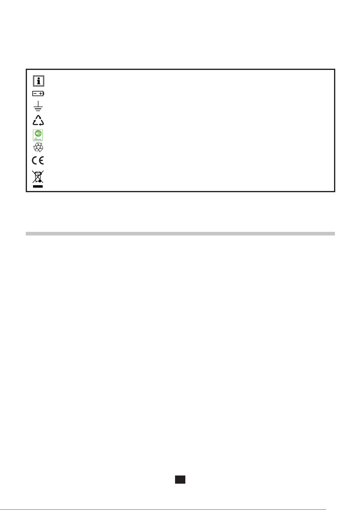
Information or useful tip.
Battery.
Earth.
The product is declared recyclable following an analysis of the life cycle in accordance with standard ISO 14040.
Chauvin Arnoux has adopted an Eco-Design approach in order to design this appliance. Analysis of the complete life-
cycle has enabled us to control and optimize the eects of the product on the environment. In particular this appliance
exceeds regulation requirements with respect to recycling and reuse.
The CE marking indicates conformity with European directives, in particular LVD and EMC.
The rubbish bin with a line through it indicates that, in the European Union, the product must undergo selective disposal
in compliance with Directive WEEE 2012/19/EU. This equipment must not be treated as household waste.
PRECAUTIONS FOR USE
This instrument is compliant with safety standard IEC 61010-2-030, for voltages 5V with report to ground. Failure to observe the
safety instructions may result in electric shock, re, explosion, and destruction of the instrument and of the installations.
The operator and/or the responsible authority must carefully read and clearly understand the various precautions to be taken
in use. Sound knowledge and a keen awareness of electrical hazards are essential when using this instrument.
Observe the conditions of use, namely the temperature, the relative humidity, the altitude, the degree of pollution, and the
place of use.
Do not use the instrument if it seems to be damaged, incomplete, or poorly close.
Before each use, check the condition of the housing. Any item of which the insulation is deteriorated (even partially) must be
set aside for repair or scrapping.
All troubleshooting and metrological checks must be done by competent, accredited personnel.
Keep your electrode in a bottle containing an electrolytic solution.
2
Page 3

CONTENTS
1. FIRST USE ............................................................................................................................................................................... 4
1.1. Delivery condition ........................................................................................................................................................... 4
1.2. Accessories .................................................................................................................................................................... 5
1.3. Replacement parts ......................................................................................................................................................... 5
1.4. Inserting the batteries ..................................................................................................................................................... 6
2. PRESENTATION OF THE INSTRUMENT ............................................................................................................................. 7
2.1. C.A 10101 ....................................................................................................................................................................... 7
2.2. Functions of the instrument ............................................................................................................................................ 8
2.3. Keypad ........................................................................................................................................................................... 8
2.4. Display ............................................................................................................................................................................ 9
2.5. Setting the time ............................................................................................................................................................... 9
2.6. Prop .............................................................................................................................................................................. 10
3. USE IN STAND-ALONE MODE ............................................................................................................................................11
3.1. pH measurement ...........................................................................................................................................................11
3.2. Oxidation reduction potential measurement (ORP) ..................................................................................................... 17
3.3. Recording the measurements ...................................................................................................................................... 20
3.4. Errors ............................................................................................................................................................................ 21
4. USE IN RECORDING MODE ...............................................................................................................................................22
4.1. Connection ................................................................................................................................................................... 22
4.2. Get Data Logger Transfer software .............................................................................................................................. 22
4.3. USB link ........................................................................................................................................................................ 22
4.4. Data Logger Transfer software ..................................................................................................................................... 25
5. TECHNICAL CHARACTERISTICS ..................................................................................................................................... 28
5.1. Reference conditions .................................................................................................................................................... 28
5.2. Characteristics .............................................................................................................................................................. 28
5.3. Memory ......................................................................................................................................................................... 30
5.4. USB .............................................................................................................................................................................. 30
5.5. Power supply ................................................................................................................................................................ 30
5.6. Environmental conditions ............................................................................................................................................. 31
5.7. Mechanical characteristics .......................................................................................................................................... 32
5.8. Compliance with international standards ...................................................................................................................... 32
5.9. Electromagnetic compatibility (EMC) ............................................................................................................................ 32
6. MAINTENANCE ..................................................................................................................................................................... 33
6.1. Cleaning ....................................................................................................................................................................... 33
6.2. Replacement of batteries .............................................................................................................................................. 34
6.3. Serial number ............................................................................................................................................................... 34
6.4. Calibration log ............................................................................................................................................................... 34
6.5. Embedded software version ......................................................................................................................................... 34
6.6. Updating the embedded software ................................................................................................................................. 34
7. WARRANTY ........................................................................................................................................................................... 37
3
Page 4
1.1. DELIVERY CONDITION
M M
MM
1. FIRST USE
➀
➂
➄
➅
➁
➃
GUIDE DE DÉMARRAGE RAPIDE DU C.A 10101 (FR)
NOTICE DE FONCTIONNEMENT
MESURE
➈
H O
2
indique la qualité de la dernière électrode étalonnée.
Le symbole
Valeur de la pente Valeur de l’asymétrie État de l’électrode
SHQWH DV\PpWULHP9
SHQWH P9DV\PpWULH38 mV
SHQWH P9DV\PpWULH58 mV
SHQWH P9DV\PpWULH
FRANCE
INTERNATIONAL
Chauvin Arnoux Group
Chauvin Arnoux Group
190, rue Championnet
Tél : +33 1 44 85 44 38
75876 PARIS Cedex 18
Fax : +33 1 46 27 95 69
Tél : +33 1 44 85 44 85
Fax : +33 1 46 27 73 89
Our international contacts
info@chauvin-arnoux.com
www.chauvin-arnoux.com/contacts
www.chauvin-arnoux.com
695716A01 - Ed. 1 - 09/2018 © Chauvin Arnoux - All rights reserved and reproduction prohibited
One C.A 10101 pH-meter.
1
One XRGST1 combined pH electrode with integrated temperature probe and storage reservoir.
2
Four AA or LR6 alkaline batteries.
3
Rendez-vous sur notre site Internet pour télécharger la notice
de fonctionnement de votre appareil et de vos électrodes :
www.chauvin-arnoux.com
Allez dans l’onglet ProduitsHWHႇHFWXH]XQHUHFKHUFKHDYHF
le nom de votre appareil. Une fois l’appareil trouvé, allez sur
sa page. La notice de fonctionnement se trouve sur la droite.
Téléchargez-la.
Procédez de même pour les électrodes de pH et ORP.
MISE EN PLACE DES PILES
LOGICIEL DATA LOGGER TRANSFER
Rendez-vous sur notre site Internet pour télécharger la dernière version du logiciel d’application :
www.chauvin-arnoux.com
Allez dans l’onglet Support, puis Télécharger nos logi-
ciels(ႇHFWXH]HQVXLWHXQHUHFKHUFKHDYHFOHQRPGHYRWUH
appareil.
Téléchargez le logiciel puis installez-le sur votre PC.
N
N
TOUCHES
Touche Fonction
Touche Marche / Arrêt (appui long)
MEM : un appui court pour enregistrer la
MEM
mesure et la température.
REC
REC : un appui long pour démarrer ou
arrêter un enregistrement.
pH/mV : un appui court pour choisir le type
de mesure (pH ou ORP).
pH/mV
°C/°F : un appui long pour choisir l’unité
°C/°F
de température.
Rétroéclairage.
CAL : un appui court pour consulter les
paramètres d’étalonnage et lancer un
CAL
étalonnage.
END
END : un appui long pour terminer l’éta-
lonnage.
Un appui court pour régler la température
Ÿ
en MTC.
Un appui long pour choisir le set de solu-
ź
tions tampons pendant l’étalonnage.
ÉTAT DE LIVRAISON
Le pH-mètre C.A 10101 est livré dans une mallette de
transport avec :
Une électrode de pH combinée avec sonde de température
intégrée XRGST1 et réservoir de stockage.
Quatre piles alcaline AA ou LR6.
Une gaine de protection montée sur l’appareil.
Deux solutions tampons NIST prêtes à l’emploi de pH
4,01 et 7,00.
Deux béchers.
Un cordon USB - micro USB.
Une dragonne.
Des guides de démarrage rapide (un par langue).
8QHDWWHVWDWLRQGHYpUL¿FDWLRQ
➉
ATTESTATION DE VERIFICATION
CHECKING ATTESTATION
190, rue Championnet
Numéro de l'appareil :
75876 PARIS Cedex 18
Equipment number
FRANCE
Type /
:
Model
Désignation de l'instrument :
Instrument designation
Signature :
Vérifié par :
Signature
Tested by
Établi en usine, ce document atteste que le produit ci-dessus a été vérifié et est conforme aux
conditions d'acceptation définies dans nos procédures de fabrication et de contrôle.
Tous les moyens de mesure et d'essai utilisés pour vérifier cet appareil sont raccordés aux
étalons nationaux et internationaux soit par l'intermédiaire d'un de nos laboratoires de métrologie
accrédités COFRAC soit par un autre laboratoire accrédité.
Après sa mise en service, cet instrument doit être vérifié à intervalle régulier
auprès d'un service de métrologie agréé.
Pour tout renseignement veuillez contacter notre service après vente et d'étalonnage.
At the time of manufacture, this document certifies that the above product have been verified and
complies with acceptance conditions defined in our manufacturing and testing procedures.
Every test or measuring equipment used to verify this instrument are related to national
and international standards through one of our laborator
ies of metrology certified by french COFRAC
equivalent to NAMAS in the UK or through another certified laboratory.
After being in use, this instrument must be recalibrated within regular intervals
by an approved metrology laboratory. Please contact our after sales and calibration department:
Service après vente et d'étalonnage TEL: +33 (2) 31 64 51 55 FAX: +33 (2) 31 64 51 72
After sales and calibration department e-mail: info@manumesure.fr
WEB : www.manumesure.com
www.chauvin-arnoux.com
ATTESTATION DE CONFORMITE
COMPLIANCE ATTESTATION
Nous certifions que ce produit a été fabriqué conformément aux spécifications
techniques de constuction applicables.
We certify that this product is manufactured in accordance with applicable
constructing specifications.
11
907 009 119 - 02/03
➆
➇
One protective sheath tted on the instrument.
4
Two ready-to-use buer solutions, pH 4.01 and 7.00 (NIST = National Institute of Standards and Technology, United States).
5
Two beakers.
6
One USB to micro USB cable.
7
One carrying case.
8
One wrist strap.
9
Quick start guides (one per language).
10
One certicate of verication.
11
4
Page 5
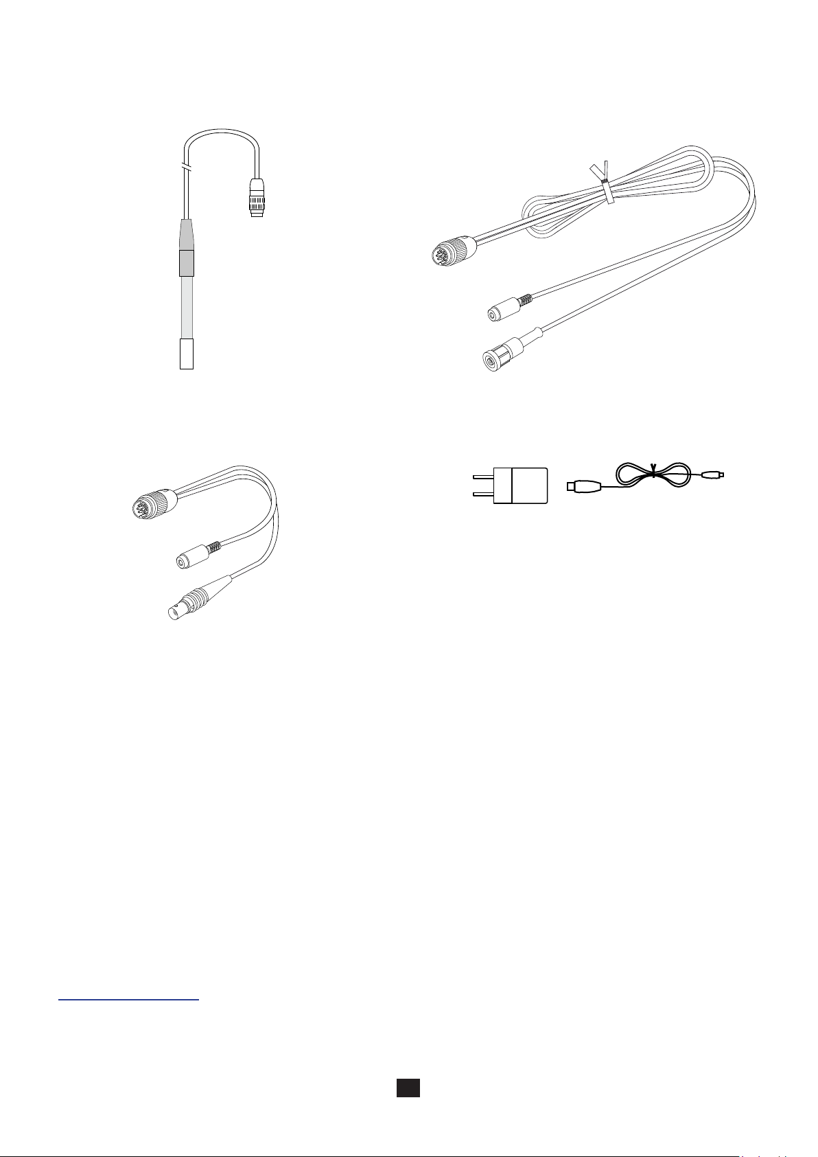
1.2. ACCESSORIES
One XRPTST1 combined ORP electrode with integrated
temperature probe and storage bottle.
One adapter DIN male to BNC female (for the electrode)
and female jack (for a PT1000 temperature probe). The
cable is 10cm long.
One adapter, DIN male to S7 female (for the electrode) and
female jack (for a PT1000 temperature probe). The cable
is 1m long.
One USB power adapter with USB to micro USB cable
One pH 1.68 buer solution (NIST).
One pH 9.18 buer solution (NIST).
One pH 10.01 buer solution (NIST).
One pH 4.005 buer solution (Cofrac certied).
One pH 6.865 buer solution (Cofrac certied).
One pH 9.180 buer solution (Cofrac-certied).
One 220mV ORP buer solution
One 468mV ORP buer solution
1.3. REPLACEMENT PARTS
One XRGST1 combined pH/temperature electrode
One pH 4.01 buer solution (NIST)
One pH 7.00 buer solution (NIST)
One set of 3 plastic beakers
One protecting sheath
Electrode storage liquid (3 mol/L KCl)
For the accessories and spares, consult our web site:
www.chauvin-arnoux.com
5
Page 6
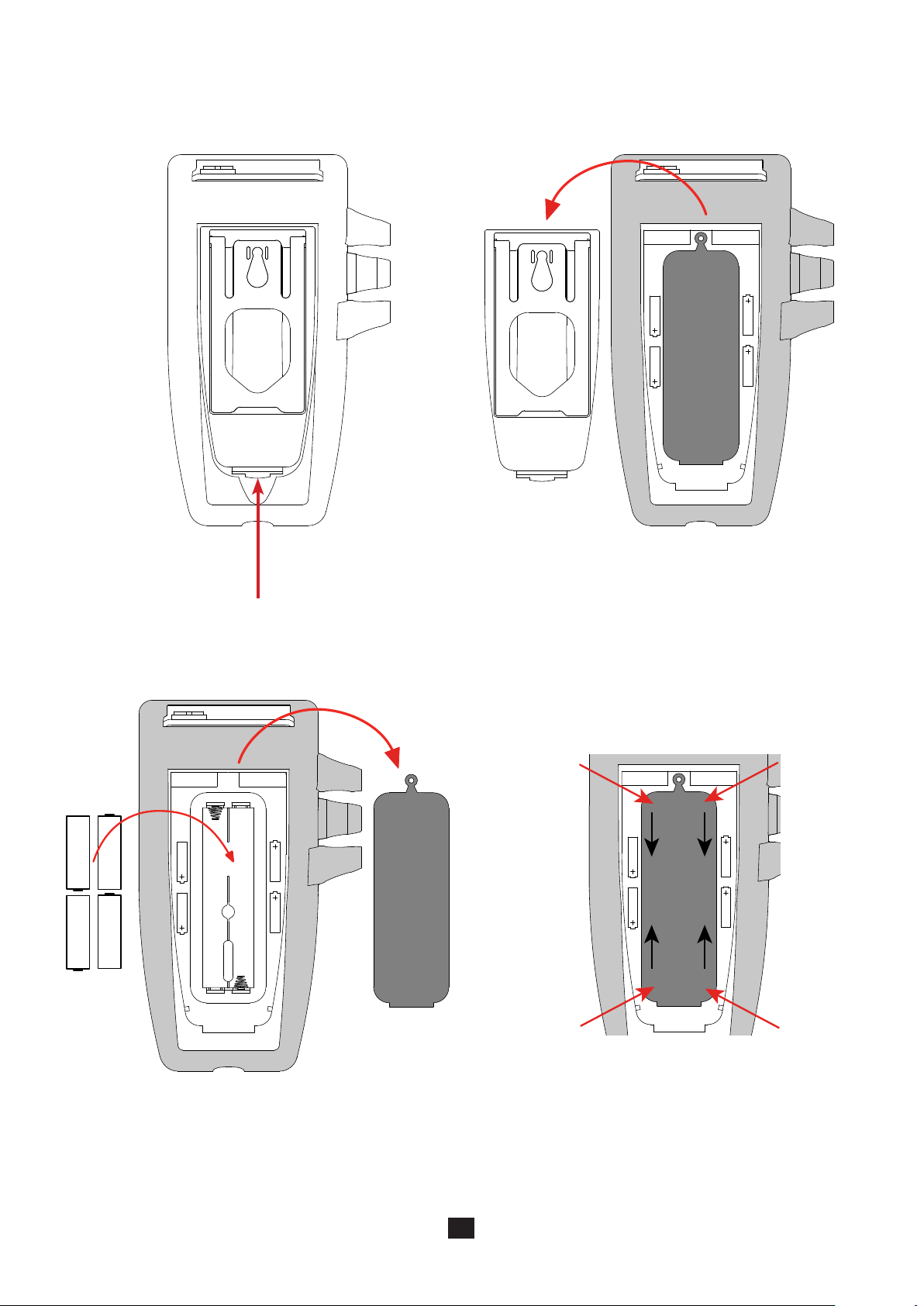
1.4. INSERTING THE BATTERIES
Turn the instrument over.
Press the locking tab and lift o the battery compartment cover.
Remove the rubber plug.
Insert the 4 batteries provided, with the polarities as shown.
Put the rubber plug back in place. Push it in correctly.
Place the two front ends before pushing in the central part.
Put the battery compartment cover back in place; make sure
that it is completely and correctly closed.
6
Page 7

2.1. C.A 10101
2. PRESENTATION OF THE INSTRUMENT
Cable.
Tight 8-point connector.
Clamping ring.
MEM
REC
pH/mV
°C/°F
CAL
END
C.A 10101
pH Meter
Combined pH electrode.
Backlit LCD display unit.
Keypad with 6 keys.
Protecting sheath.
Storage bottle.
On/O key.
Wrist strap.
Type B micro USB connector protected by a cap.
7
Page 8

2.2. FUNCTIONS OF THE INSTRUMENT
The C.A 10101 is a pH-meter in a watertight housing. It can be used to measure pH, temperature, and oxidation reduction potential
(ORP), depending on which electrode is connected.
This instrument is easy to use. It has extensive stand-alone capabilities and can be used:
to calibrate the electrode using a set of buer solutions,
to automatically identify the pH buer solution,
to display temperature measurements in °C or in °F,
to display the time,
to record the measurements,
to communicate with a PC via a USB cable.
The Data Logger Transfer software can be installed on a PC and is used to congure the instruments, to program a recording
session and to recover the recorded measurements.
2.3. KEYPAD
The functions indicated above the line on the keys are accessed by a short press.
The functions indicated below the line are accessed by a long press.
To prevent inadvertently switching the instrument on, the On/O key requires a long press.
Key Function
MEM
REC
pH/mV
°C/°F
CAL
END
▲
▼
A long press on the key switches the instrument on.
A second long press on the key switches the instrument o when it is on.
The instrument cannot be switched o while it is recording.
A short press on the MEM key records the measurement and the temperature.
A long press on the REC key starts or stops a manual recording session.
A short press on the pH/mV key selects the type of measurement (pH or ORP) that matches the electrode
connected.
A long press on the °C/°F key selects display of the temperature measurement in °C or in °F.
A short press on the key toggles the backlighting on and o. Once lit, it goes o after 30 seconds.
A short press on the CAL key is used to look up the current calibration and start the calibration procedure for
the cell connected.
A long press on the END key is used to terminate the calibration procedure in progress.
A short press on the ▲ or ▼ key is used to set the temperature in manual mode.
During the calibration, a long press on the ▲ or ▼ key selects the calibration set.
8
Page 9
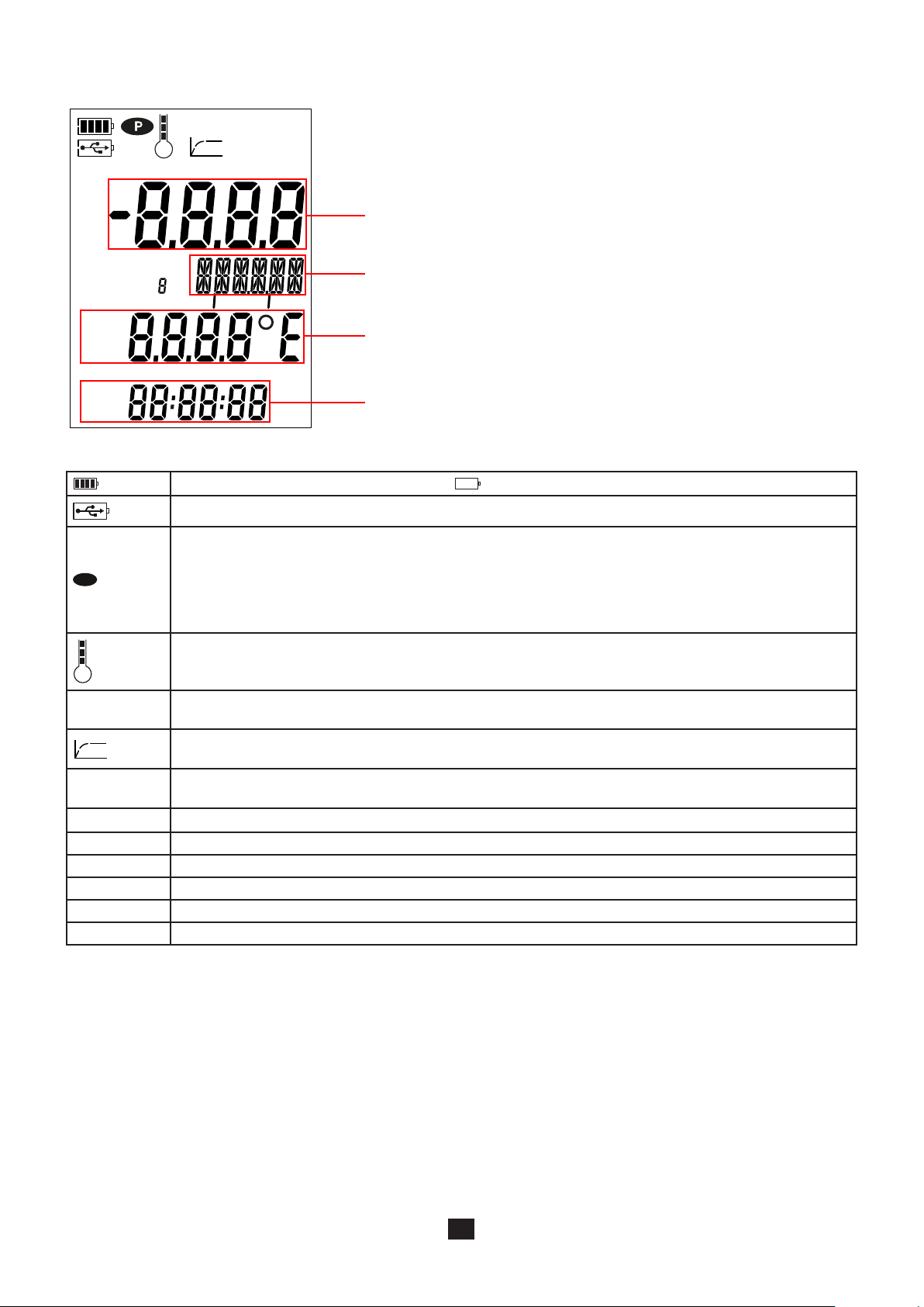
2.4. DISPLAY
P
%
OFFSET
CAL SET
MTC
ATC
AM
PM
MEM FULL
Indicates the battery voltage level. When the symbol is empty, the batteries must be replaced.
Indicates that the instrument is connected to a PC via the USB cable or that the power adapter is connected.
Indicates that auto-o is disabled and the instrument is in permanent mode.
This occurs when:
a calibration is in progress,
a recording is in progress,
the instrument is connected via the USB cable,
auto o is deactivated (see §4.4.3).
REC
MEM
Display of the measurement.
Display of the unit.
Display of the temperature.
Display of the time.
Indicates the quality of the last electrode calibrated.
MEM FULL
REC
MEM Indicates that a measurement is recorded.
% Indicates the slope of the electrode.
OFFSET Indicates the oset of the electrode.
CAL SET Indicates that calibration is in progress.
MTC Indicates that temperature compensation is manual.
ATC Indicates that temperature compensation is automatic.
When the measurement exceeds the limits (whether positive or negative), the instrument displays OL.
When lit steadily, indicates that the instrument’s memory is full.
When blinking, indicates that the instrument’s memory is 90% full.
Indicates the progress of the measurement. When all segments are lit, the measurement is stable.
When blinking, indicates that the measurement is over or that the calibration has been applied.
When lit steadily, indicates that recording is in progress.
When blinking, indicates waiting for the start of a recording session.
2.5. SETTING THE TIME
The time of your instrument is set using the Data Logger Transfer software. Refer to §4.4.2.
9
Page 10

2.6. PROP
To make reading easier, the instrument can be set on its prop.
10
Page 11

3. USE IN STAND-ALONE MODE
> 2s
The instrument can operate in two modes:
the stand-alone mode described in this section,
the record mode, in which it is controlled by a PC. This mode is described in the next section.
In order to ensure proper operation of the instrument, always leave the electrode connected and the cap on the USB connector closed.
Keep your electrode in a bottle containing an electrolytic solution. Never keep the electrode in distilled or de-ionized water.
3.1. PH MEASUREMENT
3.1.1. FIRST USE
During the rst use, connect the pH electrode supplied to the measuring instrument. Connect the connector of the electrode to
the instrument and screw the ring tight.
3.1.2. CALIBRATION
The C.A 10101 is delivered with two buer solutions (NIST), pH 4.01 and 7.00.
You can calibrate at one point, two points, or three points. Two solutions are provided with the instrument, the third is an option.
Remove the storage bottle from the electrode. Rinse the electrode in de-ionized water, then dry it.
H O
2
Pour each buer solution (one, two, or three depending on
the number of calibration points) into a beaker. The third
buer solution (NIST, pH 9.18) is an option.
Long-press the key to switch the instrument on.
4,01
7,00
9,18
11
Page 12
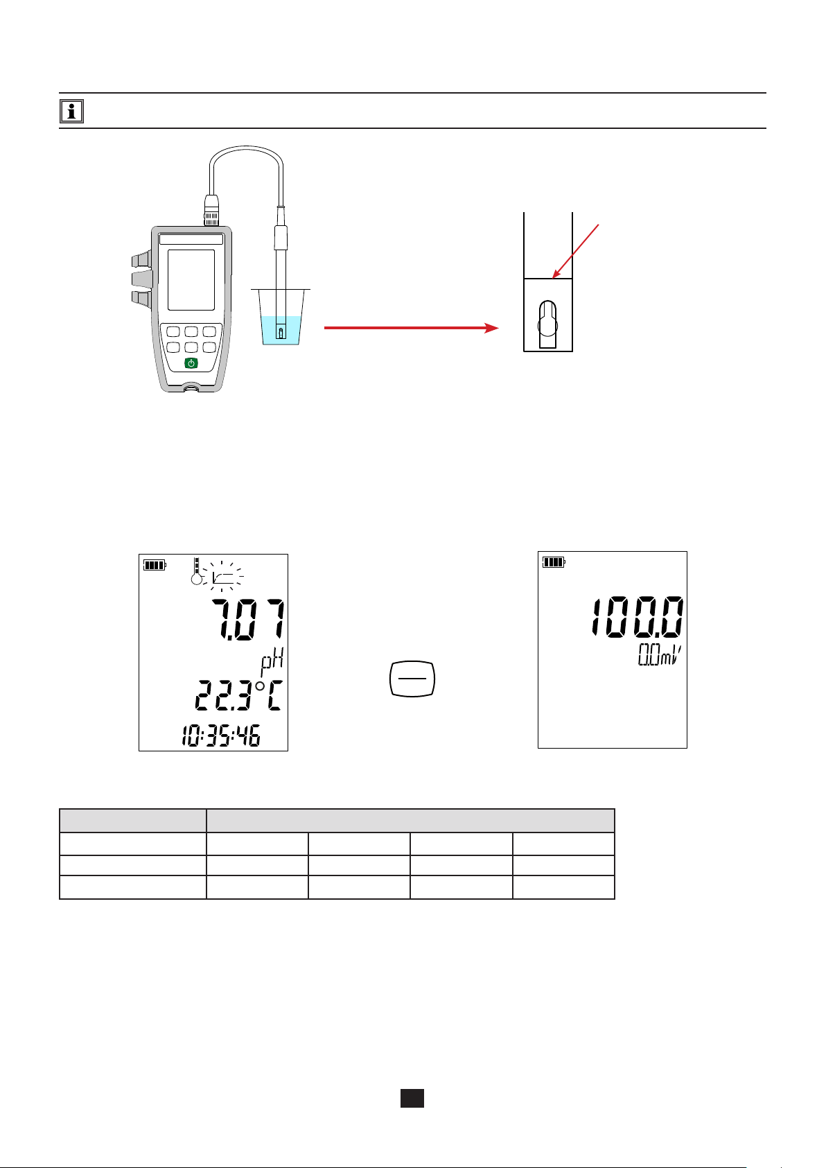
If you spot an air bubble on the glass membrane, shake the electrode to eliminate it.
Plunge the end of the electrode in the rst buer solution.
Take care to completely submerge the glass ball and the salt bridge in the solution.
Minimum level of immersion.
The electrode supplied with the instrument has an integrated temperature probe. There is therefore no need to measure the temperature of the solution.
The instrument displays the pH and temperature meas-
urements and the time.
ATC = Automatic Temperature Compensation
Press the CAL key.
The instrument briey displays the current calibration values
(the slope in % and the oset in mV).
%
OFFSET
CAL
END
ATC
It then proposes selecting the calibration set. Three sets are available.
pH at 25°C
Calibration set 1 4.01 7.00 9.18
Calibration set 2 1.68 4.01 7.00 10.01
Calibration set 3 4.005 6.865 9.180
Calibration set 3 contains the Cofrac-certied buer solution pH values.
If you have your own calibration set, you can change these values in the pH_Set.csv le (see §4.3).
12
Page 13

Choose the calibration set by long presses on the ▲ and
▼ keys. The values of the buer solutions supplied are
in set 1.
Conrm the set by pressing the CAL key.
When the instrument detects the buer solution value, it
displays it, corrected for temperature, in alternation with
the temperature.
CAL SET
ATC
The instrument performs the pH measurement and indicates its progress.
Do not withdraw the electrode from the solution until the measurement is over.
If you want to abort the calibration of the electrode, long-press the END, key before the end of the measurement.
Otherwise, when the measurement has stabilized ,
the rst calibration point is applied. The instrument then informs
you that you can calibrate a second point.
The pH values of the calibration set are scrolled.
CAL
END
CAL SET
ATC
The value of the buer solution of the calibration set is always
displayed in alternation with the temperature.
The CAL and END symbols are also displayed in alternation,
indicating that you can continue or terminate the calibration.
If you need only one calibration point, long-press the END key. Only the oset of the electrode will be calculated; the slope will
be left unchanged.
The instrument exits from the calibration procedure and briey displays the slope and the oset before switching back to
measurement mode.
CAL SET
ATC
%
> 2s
CAL
END
OFFSET
13
Page 14

If you want to continue the calibration, withdraw the electrode from the solution, rinse it with de-ionized water, dry it, plunge it
in the second buer solution, and press the CAL key again.
CAL
END
H O
2
Wait for the measurement to stabilize. Once again, the instrument proposes terminating the calibration (by pressing the END
key) or continuing at a third point (by pressing the CAL key).
CAL SET
ATC
If two calibration points are enough, long-press the END key. The slope and oset of the electrode will be calculated and displayed.
However, you can continue the calibration on a third and last point by pressing the CAL key again.
CAL SET
ATC
%
> 2s
CAL
END
OFFSET
During the calibrations, the slope and oset of a given electrode must not vary more than a little. If you observe a large
variation, redo the calibration. If the problem persists, check the buer solution (in particular the use-by dates) or replace
the electrode.
14
Page 15

3.1.3. RESTORE THE INITIAL CALIBRATION
Press the CAL key, then the MEM key.
CAL
END
If you do not want to restore the initial calibration, choose no before pressing the CAL key.
Otherwise, choose YES and press the CAL key. The calibration values return to 100% for the slope and 0.0 mV for the oset.
3.1.4. MEASUREMENTS
Once the calibration is over, the electrode is ready to make measurements.
Between measurements, the electrode must be rinsed and dried. When you have nished using it, put it back in its storage
bottle.
For each measurement, wait until the measurement has stabilized and the temperature is correctly established.
MEM
REC
CAL
END
The symbol indicates the quality of the electrode just calibrated. This lets you track the evolution of the state of your electrode
and replace it when necessary.
Slope Oset
95% ≤ slope ≤ 105% oset ≤ 19 mV
90% ≤ slope < 95% 19 mV < oset ≤ 38 mV
85% ≤ slope < 90% 38 mV < oset ≤ 58 mV
105% < slope < 85% 58 mV < oset
It is the less good of the 2 states (slope and oset) that should be applied.
State of the
electrode
15
Page 16

3.1.5. USE OF ANOTHER PH ELECTRODE
The electrode supplied with the instrument has an integrated temperature probe. If you use another electrode, one without an
integrated temperature probe, you must measure the temperature of the solution.
The instrument indicates that the temperature can be modied by displaying MTC next to the temperature.
MTC = Manual Temperature Compensation.
You must then correct the temperature displayed, using the ▲ and ▼ keys, so that it is equal to the measured temperature of the
solution.
MTC
The instrument corrects the response of the electrode for temperature.
To calibrate the electrode, always correct the temperature rst. And make sure that all of the buer solutions are at the same
temperature.
To connect your electrode, use one of the optional connection adapters (see § 1.2). These adapters also let you connect a PT1000
probe.
16
Page 17

3.2. OXIDATION REDUCTION POTENTIAL MEASUREMENT (ORP)
> 2s
ORP = Oxidation Reduction Potential
3.2.1. FIRST USE
During the rst use, connect the ORP electrode (optional) to the measuring instrument. Connect the connector of the electrode to
the instrument and screw the ring tight.
3.2.2. CALIBRATION
Calibration is done at a single point.
Remove the storage bottle from the electrode.
Pour the buer solution into a beaker.
Rinse the electrode in de-ionized water, then dry it.
H O
2
Long-press the key to switch the instrument on.
Press the pH/mV key to switch to oxidation reduction po-
tential measurement.
pH/mV
°C/°F
17
Page 18

If you spot an air bubble on the diaphragm, shake the electrode to eliminate it.
Plunge the end of the electrode into the calibration solution.
Take care to completely submerge the salt bridge in the solution.
Minimum immersion level.
The electrode (optional) has an integrated temperature probe. There is therefore no need to measure the temperature of the solution.
The instrument displays the ORP and temperature meas-
urements and the time.
ATC = Automatic Temperature Compensation.
CAL
END
ATC
It then proposes selecting the calibration set. Two sets are available.
ORP at 25°C (mV)
Calibration set 1 220
Calibration set 2 468
Press the CAL key.
THE instrument briey displays the current calibration value
(the oset in mV).
OFFSET
If you have your own calibration solutions, you can change these values in the ORP_Set.csv le (see §4.3).
18
Page 19

Choose the calibration set by long presses on the ▲ and
▼ keys.
Validate the set by pressing the CAL key.
When the instrument detects the value of the buer solution,
it displays it in alternation with the temperature.
CAL SET
The instrument makes the ORP measurement and indicates its progress.
Do not withdraw the electrode from the solution until the measurement is over.
If you want to abort the calibration of the electrode, long-press the END key before the end of the measurement.
Otherwise, when the measurement has stabilized , the calibration is applied. Press the CAL key. The instrument briey
displays the oset before returning to measurement mode.
CAL
END
OFFSET
CAL
END
During the calibrations, the oset of a given electrode must not vary more than a little. If you observe a large variation, redo
the calibration. If the problem persists, check the buer solution (in particular the use-by dates) or replace the electrode.
19
Page 20

3.2.3. RESTORE THE INITIAL CALIBRATION
Press the CAL key, then the MEM key.
CAL
END
If you do not want to restore the initial calibration, choose no before pressing the CAL key.
Otherwise, choose YES and press the CAL key. The oset returns to 0.0 mV.
3.2.4. MEASUREMENTS
Once the calibration is over, the electrode is ready to make measurements.
Between measurements, the electrode must be rinsed and dried. When you have nished using it, put it back in its storage
bottle.
For each measurement, wait for the measurement to stabilize.
MEM
REC
CAL
END
3.3. RECORDING THE MEASUREMENTS
A short press on the MEM key records the measurement with the date and time. The MEM symbol is displayed briey.
It is not possible to record a single measurement while the instrument is already recording.
A long press on the REC key starts or stops a recording session. The REC symbol remains displayed for the duration of a
recording session. Auto o is deactivated (this means that the instrument is in permanent mode) and the P symbol is dis-
played.
If the REC symbol ashes, a recording session has been programmed and is pending.
Before starting a recording session, make sure that the battery life is sucient, or else connect the instrument to an external
power supply on/to a wall outlet using a micro USB cord.
When the memory is 90% full, the MEM FULL symbol blinks. When the memory is full, the MEM FULL symbol stops blinking.
To see the records, you must use a PC and install the Data Logger Transfer software (see §4).
20
Page 21

3.4. ERRORS
The instrument detects errors and displays them in the form Er.XX. The main errors are the following:
Er.01: Hardware malfunction detected. The instrument must be sent in for repair.
Er.02: Error in internal memory. Format it using Windows.
Er.03: The update of the internal software is not compatible with the instrument (the software is that of another instrument of the
line). Install the correct internal software in your instrument.
Er.10: The instrument has not been calibrated or the calibration is not in conformity. The instrument must be sent back to customer
service.
Er.12: The update of the internal software is not compatible with the electronic boards in the instrument. Reload the previous
internal software into your instrument.
Er.13: Recording scheduling error. Check that the instrument’s time and the time of the Data Logger Transfer software are the
same.
Er.14: Calibration error. The measured value is too far from the value of the standard solution of the selected calibration set. Check
that the solution used in fact belongs to the selected set. If necessary, return to the initial calibration (see §3.1.3).
Er.15: Calibration error. The stabilization time is too long.
Er.16: pH calibration error. Two buer solutions having the same value were used for the calibration.
Er.17: Calibration error. The calculated oset is too large. Redo the calibration. If the error persists, check the buer solution or
replace the electrode.
Er.18: pH calibration error. The calculated slope is too large (> 105%) or too small (< 85%). Redo the calibration. If the error per-
sists, check the buer solution or replace the electrode.
Er.19: Calibration error. The temperature (ATC or MTC) is outside of the specications of the buer solutions. Redo the calibration
in a room where the temperature lies within the specications of the buer solution (see the pH_Set.csv le §4.3).
Er.20: Calibration error. The le dening the set of calibration solutions is missing. Download it from our web site:
www.chauvin-arnoux.com
Er.21: Calibration error. The le dening the set of calibration solutions is not in conformity. Check that it is the right le. If you have
modied it, check the format; in particular, the decimal separators must be points, not commas.
Er.22: Recording error. Power was cut o while recording was in progress.
Er.50: Calibration error. Measurement error for the calibration.
To exit from calibration errors, press the CAL key or the END key.
21
Page 22

4. USE IN RECORDING MODE
The instrument can operate in two modes:
the stand-alone mode described in the previous section,
the record mode, in which it is controlled by a PC. This mode is described below.
4.1. CONNECTION
The instrument communicates by a USB link, using the USB to micro USB cord provided.
4.2. GET DATA LOGGER TRANSFER SOFTWARE
Visit our web site to download the latest version of the application software:
www.chauvin-arnoux.com
Go to the Support tab, then Download our software. Then search on the name of your instrument.
Download the software, then install it on your PC.
You must have administrator privileges on your PC to install the Data Logger Transfer software.
Minimum computer requirements:
Windows 7 (32/64 bits)
2 GB of RAM
200 MB of disc space
Windows® is a registered trade mark of Microsoft®.
Do not connect the instrument to the PC until you have installed the Data Logger Transfer software.
4.3. USB LINK
Long-press the key to switch the instrument on.
Once the Data Logger Transfer software has been installed,
connect the instrument to the PC.
22
The symbol blinks.
Page 23

The instrument is treated as a USB key.
If you click Open the folder and display the les, you can access its contents. But to read the records, you must use the Data
Logger Transfer software.
In the contents, you will nd the pH_Set.csv and ORP_Set.csv les. You can open and modify these les using a spreadsheet:
add or remove a calibration set
modify a calibration set by adding, removing, or modifying buer solutions.
Do not change the structure of the le.
For the ORP_Set.csv le
Number of calibration sets.
Calibration set number.
Number of buer solutions in the calibration set (only
one per set).
ORP of the buer solutions in mV.
23
Page 24

For the pH_Set.csv le
Number of calibration sets.
Calibration set number (1, 2, 3 ..).
Number of buer solutions in the calibration set.
pH of the buer solution.
pH of the buer solution vs temperature.
24
Page 25

4.4. DATA LOGGER TRANSFER SOFTWARE
Once the instrument is connected to the PC, open the Data Logger Transfer software.
For context-sensitive information about the use of the Data Logger Transfer software, refer to the Help menu.
4.4.1. CONNECTING THE INSTRUMENT
To connect an instrument, click Add an instrument, then choose the type of connection (USB).
A window opens with a list of all instruments connected to the PC.
The name of the instrument will be formed from the model of the instrument and the warranty number: CA10141 - 123456ABC.
You can personalize your instrument by adding a name and a location, by clicking on or .
Choose your instrument in the list. The instrument then displays complete information about the instrument and its measure-
ments in progress.
4.4.2. DATE AND HOUR
In the Instrument menu, the icon lets you set your instrument’s date and time.
These cannot be changed while recording or when a recording session has been scheduled.
By clicking , you can choose the date and time display formats.
4.4.3. AUTO OFF
As default, the instrument switches itself o automatically after 5 minutes of operation without the user’s presence being conrmed
by a key-press. By clicking , you can change this value to 3, 10, or 15 minutes.
It is also possible to disable this auto-o function; the instrument then displays the P symbol.
25
Page 26

4.4.4. PROGRAMMED RECORDING SESSIONS
By clicking , you can program a recording session. Assign a name to the recording session. Then enter a starting date and time
and an ending date and time or a duration. The maximum duration of a recording session depends on the memory available.
Choose a sampling period. The possible values are: 1 s, 2 s, 5 s, 10 s, 20 s, 30 s, 1 min, 2 min, 5 min, 10 min, 15 min, 30 min and
1 hour. The shorter the sampling period, the larger the recorded le.
Before and after the recording session, if the instrument is switched on, the sampling period will be that of the stand-alone mode (1s).
If the instrument is o when recording starts, it switches itself on by itself. Then it displays the measurement, which it refreshes at
each sampling period.
The REC symbol blinks on the display unit of the instrument to report that a recording session is pending. It stops blinking when
the recording starts.
Before starting a recording session, make sure that the battery life is sucient, or else connect the instrument to an external
power supply to a wall outlet using a USB cord.
4.4.5. DISPLAY
By clicking , then going to the pH-meter tab, you can modify the display of the measurements on the instrument in the same
ways as by pressing the pH/mV or °C/°F key.
4.4.6. READING THE RECORDS
The Data Logger Transfer software lets you read the records made. Click Recorded Sessions under the name of your instrument
to obtain a list of the records.
4.4.7. EXPORTING RECORDS
Once the list of the records is displayed, choose the one you want to export and convert it into a word-processing document (docx)
or a spreadsheet (xlsx), in order to be able to use it in the form of reports or curves.
It is also possible to export the data to the DataView application software (see §1.2).
4.4.8. REAL-TIME MODE
Click Real-time data under the name of your instrument to see the measurements being made on the instrument as they are made.
26
Page 27

4.4.9. FORMATTING THE MEMORY OF THE INSTRUMENT
The internal memory of the instrument is already formatted. But if there is a problem (if it becomes impossible to read or to write),
it may be necessary to reformat it (in Windows).
In this case, all of the data will be lost.
27
Page 28

5. TECHNICAL CHARACTERISTICS
5.1. REFERENCE CONDITIONS
Quantity of inuence Reference values
Temperature 23 ± 3°C
Relative humidity 45% to 75%
Battery supply voltage 4 to 6.4V
USB supply voltage 5V ± 5%
Electric eld < 1V/m
Magnetic eld < 40A/m
The intrinsic uncertainty is the error specied for the reference conditions.
It is expressed in % of the reading (L) and in mV.
± (a % L + b)
5.2. CHARACTERISTICS
The intrinsic uncertainties on the measurements are given for the instrument alone. The uncertainty of the electrode used must
be added to them.
5.2.1. PH MEASUREMENTS
Instrument alone
Specied measurement range -2.00 to 16.00
Resolution (R) 0.01
Intrinsic uncertainty of the instrument
alone, without the electrode (E)
Instrument + XRGST1 pH electrode
Specied measurement range: 1.00 to 12.00 pH
5.2.2. ORP MEASUREMENTS
Specied measurement range -199.9 to +199.9 mV -1,999 to -200 and +200 to +1,999 mV
Resolution (R) 0.1 mV 1 mV
Intrinsic uncertainty of the instrument
alone, without the electrode (E)
5.2.3. TEMPERATURE MEASUREMENTS
The temperature measurements are made using a PT1000 resistive probe integrated in the electrode
± 0.01 ± R
± 0.1 mV ± R ± 1 mV ± R
Specied measurement range - 10.0 to + 120.0°C 14.0 to 248.0°F
Resolution (R) Display in °C: 0.1°C Display in °F: 0.1°F
Intrinsic uncertainty of the instrument
alone, without the electrode (E)
< 0.4°C < 0.7°F
28
Page 29

5.2.4. INFLUENCE OF THE TEMPERATURE ON THE VALUES OF THE BUFFER SOLUTIONS
The pH values of the buer solutions sold by Chauvin Arnoux vary as a function of the temperature as specied in the table below.
Temperature
°C / °F
0°C / 32°F
10°C / 50°F
15°C / 59°F
20°C / 68°F
25°C / 77°F
30°C / 86°F
40°C / 104°F
50°C / 122°F
Temperature
°C / °F
0°C / 32°F
10°C / 50°F
15°C / 59°F
20°C / 68°F
25°C / 77°F
30°C / 86°F
40°C / 104°F
50°C / 122°F
Buer solution
pH 1.68
NIST
1.67
1.67
1.67
1.68
1.68
1.68
1.69
1.71
Buer solution
pH 4,005
Cofrac-certied
4.000
3.997
3.998
4.001
4.005
4.011
4.027
4.050
Buer solution
pH 4.01
NIST
4.01
4.00
4.00
4.00
4.01
4.01
4.03
4.06
Buer solution
pH 6,865
Cofrac-certied
6.984
6.923
6.900
6.881
6.865
6.853
6.838
6.833
Buer solution
pH 7.00
NIST
7.12
7.06
7.04
7.02
7.00
6.99
6.97
6.97
Buer solution
pH 9,180
Cofrac-certied
9.464
9.332
9.276
9.225
9.180
9.139
9.068
9.010
Buer solution
pH 9.18
NIST
9.46
9.33
9.28
9.23
9.18
9.14
9.07
9.02
Buer solution
pH 10.01
NIST
10.32
10.18
10.12
10.06
10.01
9.97
9.89
9.83
5.2.5. INFLUENCE OF THE TEMPERATURE ON THE PH MEASUREMENT
The instrument corrects the response of the XRGST1 electrode as a function of temperature.
During the calibration, the values of the buer solutions are corrected for the temperature per the tables above.
5.2.6. INFLUENCE OF TEMPERATURE
Inuence of temperature (from -10°C to 55°C at 50% RH) on the C.A 610101.
Type of measurement Inuence of temperature
pH measurement < 0.02 pH
Oxidation reduction potential (ORP) measurement < E ± R
Temperature measurement
The values of E and R are given in §5.2.1.
from 10 to 55°C: < 0.2°C
outside of this range: < 0.3°C
29
Page 30

5.2.7. INFLUENCE OF HUMIDITY
Inuence of humidity (from 25 to 90% RH at 25°C) on the C.A 610101.
Type of measurement Inuence of humidity
pH measurement < 0.02 pH
Oxidation reduction potential (ORP) measurement
Temperature measurement < 0.2°C
The values of E and R are given in §5.2.1.
< E ± R
5.3. MEMORY
The size of the ash memory containing the records is 8 MB.
This capacity is sucient to record more than 100,000 measurements. Each measurement is recorded with the date and time.
5.4. USB
Protocol: USB Mass Storage
Maximum transmission speed: 12 Mbit/s
Type B micro-USB connector B
5.5. POWER SUPPLY
The instrument is supplied by three 1.5V LR6 or AA alkaline batteries. It is possible to replace the batteries by rechargeable NiMH
batteries of the same size. But the rechargeable batteries, even when correctly charged, will not reach the voltage of the alkaline
batteries and the life indicated will be or .
The voltage range ensuring correct operation is from 4.0 to 6.4 V for the alkaline batteries and 4.0 to 5.2 V for the rechargeable
batteries.
Below 4V, the instrument stops making measurements and displays BAt.
Battery life is 300 h.
30
Page 31

The instrument can also be powered via a USB-micro USB cord, connected either to a PC or to a wall outlet via a mains adapter.
The symbol is displayed in this case.
> 110 VAC
< 240 VAC
50 / 60 Hz
1 W
Connecting the external USB supply does not recharge the storage batteries.
5.6. ENVIRONMENTAL CONDITIONS
Instrument for indoor and outdoor use.
Altitude < 2000m, and 10,000m in storage.
Pollution degree 2
% RH
90
80
70
60
50
40
30
3 2 1
20
10
0
-30 -20
-40 50
1 = Range of reference.
2 = Range of use.
3 = Storage range (with neither primary nor rechargeable batteries. Except electrodes and buer solutions.)
-10
4010 30200 60 8070
31
°C
Page 32

5.7. MECHANICAL CHARACTERISTICS
Dimensions (L x W x D) 211 x 127 x 54mm with the sheath
Dimensions (L x W x D) 206 x 97 x 49mm without the sheath
Mass of the instrument approximately 600 g
Mass with the electrode approximately 720 g
Inrush protection IP 67 per IEC 60 529, with the USB connector closed and the electrode connected.
IP 20 otherwise.
Drop impact test 1.50m.
5.8. COMPLIANCE WITH INTERNATIONAL STANDARDS
The instrument is compliant with standard IEC 61010-2-30.
5.9. ELECTROMAGNETIC COMPATIBILITY (EMC)
The instrument is compliant with standard IEC 61326-1.
The inuence of EMC is at most 0.25 pH.
32
Page 33

6. MAINTENANCE
Except for the batteries, the instrument contains no parts that can be replaced by personnel who have not been
specially trained and accredited. Any unauthorized repair or replacement of a part by an “equivalent” may gravely impair safety.
6.1. CLEANING
6.1.1. INSTRUMENT
Switch the instrument o.
Use a soft cloth, dampened with soapy water. Rinse with a damp cloth and dry rapidly with a dry cloth or forced air. Do not use
alcohol, solvents, or hydrocarbons.
The two parts of the connector (instrument end and electrode end) must remain perfectly clean and dry. This is why it is best to
leave the electrode connected to the instrument at all times.
At the event of immersion, dry the USB connector and the electrode connector of the instrument.
6.1.2. ELECTRODE
For the cleaning and maintenance of the electrodes, refer to their instruction sheets.
6.1.3. PROTECTIVE SHEATH
To remove the protective sheath, rst disconnect the electrode, then remove the wrist strap.
Free the bottom of the casing from the sheath
Then withdraw the housing from the sheath.
33
Page 34

6.2. REPLACEMENT OF BATTERIES
The symbol indicates the remaining battery life. When the symbol is empty, all of the batteries must be replaced.
Switch the instrument o.
Refer to §1.4 for the replacement procedure.
Spent batteries must not be treated as ordinary household waste. Take them to the appropriate recycling collection
point.
When the batteries are removed, the time is preserved for approximately two minutes.
6.3. SERIAL NUMBER
If you ever need to send your instrument in for repair, it will be helpful to know its serial number. It is found in the guarantee.txt le.
This le is in your instrument’s memory. To access it, simply connect the USB cord (see § 4.3).
The serial number is also marked on a label under the batteries.
6.4. CALIBRATION LOG
At each calibration, information is entered in the calib_log.txt le:
the date and time, the slope and oset, the pH values on which the calibration was done.
the date and time, the oset, the ORP value on which the calibration was done.
This le is in your instrument’s memory. To access it, simply connect the USB cord (see § 4.3).
6.5. EMBEDDED SOFTWARE VERSION
To look up the version number of the embedded software in your instrument, press the MEM and keys simultaneously. The
instrument displays the number for a few seconds, then returns to measurement mode.
6.6. UPDATING THE EMBEDDED SOFTWARE
With a view to providing, at all times, the best possible service in terms of performance and technical improvements, Chauvin
Arnoux oers you the possibility of updating the internal software of this instrument by downloading, free of charge, the new
version available on our web site.
See you on our site:
www.chauvin-arnoux.com
Then go to “Support”, then “Download our software”, then “C.A 10101”.
Updating the embedded software may reset the conguration and cause the loss of the recorded data. As a precaution,
save the data in memory to a PC before updating the embedded software.
34
Page 35

Download the .bin le from our web site, then press and hold the MEM key and switch the instrument on by pressing the key.
> 2s
The instrument displays BOOT.
+
MEM
REC
Release the keys and the instrument displays COPY, indicating that it is ready to receive the new software.
Connect the instrument to your PC using the USB cord provided.
35
Page 36

Copy the .bin le to the instrument as if were a USB key.
When the copying is done, press the MEM key and the instrument displays LOAD, indicating that the software is being installed.
When installation is done, the instrument displays PASS or FAIL according to whether or not the operation succeeded. If installation
fails, download the software again and repeat the procedure.
Then the instrument restarts normally.
After the internal software is updated, it may be necessary to recongure the instrument; see§ 4.4.
36
Page 37

7. WARRANTY
Except as otherwise stated, our warranty is valid for 24 months starting from the date on which the equipment was sold. Extract
from our General Conditions of Sale provided on request.
The warranty does not apply in the following cases:
Inappropriate use of the equipment or use with incompatible equipment;
Modications made to the equipment without the explicit permission of the manufacturer’s technical sta;
Work done on the device by a person not approved by the manufacturer;
Adaptation to a particular application not anticipated in the denition of the equipment or not indicated in the user’s manual;
Damage caused by shocks, falls, or oods.
pH electrodes are wear parts. The life of your electrode depends on how you use and maintain it. The electrodes are warranted
for 12 months.
The warranty does not apply if the glass is broken.
37
Page 38

695715A02 - Ed. 1 - 11/2018 © Chauvin Arnoux - All rights reserved and reproduction prohibited
FRANCE
Chauvin Arnoux Group
190, rue Championnet
75876 PARIS Cedex 18
Tél : +33 1 44 85 44 85
Fax : +33 1 46 27 73 89
info@chauvin-arnoux.com
www.chauvin-arnoux.com
INTERNATIONAL
Chauvin Arnoux Group
Tél : +33 1 44 85 44 38
Fax : +33 1 46 27 95 69
Our international contacts
www.chauvin-arnoux.com/contacts
 Loading...