

Page 1
: tensions,
ez les instructions de sécurité suivantes avant
d’utiliser l’appareil. Il est impératif de suivre les
Cet appareil n’est pas un Vérificateur
de test et de mesure connectés directement aux
de test et de mesure connectés aux parties de
Exemple : Les mesures sur les tableaux de
bus, les boîtiers de dérivation, les
équipements tels que les moteurs branchés en
Cette partie de l’installation peut ne pas avoir de
avant le fusible principal ou le disjoncteur de
les cordons préalablement au
de tension avant d’utiliser la
L’ensemble du matériel a été vérifié
mécaniquement et électriquement avant
Toute action sur la touche HOLD ou le
touche, 2 piles 1.5V AAA et cette notice de
Multimètre de p oc he numérique
Multímetro de bolsillo digital
C.A 702
FR ANC AIS
Mode d’Emploi
03 – 2015
Digital Pocket Multimeter
Digitalen Taschen-Multimeters
Multimetro ta sc a bi le di gitale
E NGL IS H
ES PANO L
IT ALIA NO
DE UTSC H
Deutschland
Ohmstraße 1 - 77694 KEHL /RHEIN
Tél : (07851) 99 26-0 - Fax : (07851) 99 26-60
España
C/ Roger de Flor N°293 - Planta 1
08025 BARCELONA
Tél : 902 20 22 26 - Fax : 934 59 14 43
Italia
Via Sant’ Ambrogio, 23/25
20846 MACHERIO (MB)
Tél : (039) 245 75 45 - Fax : (039) 481 561
Österreich
Slamastrasse 29/2/4 - 1230 WIEN
Tél : 01 61 61 9 61-0 - Fax : 01 61 61 9 61 61
Schweiz
Moosacherstrasse 15 - 8804 AU / ZH
Tél : 044 727 75 55 - Fax : 044 727 75 56
UK
Unit 1 - Nelson Ct - Flagship Sq - Shaw Cross
Business Pk - Dewsbury, West Yorkshire - WF12 7TH
Tél : 01924 460 494 - Fax : 01924 455 328
Middle East
P.O BOX 60-154 - 1241 2020 Jal el dib- BEIRUT
Tél : (01) 890 425 - Fax : (01) 890 424
China - Shanghai Pujiang Enerdis Inst. CO. LTD
3 Floor, Buildind 1 n°381 Xiang De Road
Hongkou District - 200081 - SHANGHAI
Tél : +86 21 65 21 51 96 - Fax : +86 21 65 21 61 07
USA - d.b.a AEMC Instruments
200 Foxborough Blvd - Foxborough - MA 02035
Tél : (508) 698-2115 - Fax : (508) 698-2118
190, rue Championnet - 75876 PARIS Cedex 18 - FRANCE
Tél. (33) 01 44 85 44 85 - Fax (33) 01 46 27 73 89
User’s Manual
Manual de Ins tr uccio nes
L ibre tto d’ Is truzi oni
B edienungsa nleitung
Code 691587A00_Ed05
http://www.chauvin-arnoux.com
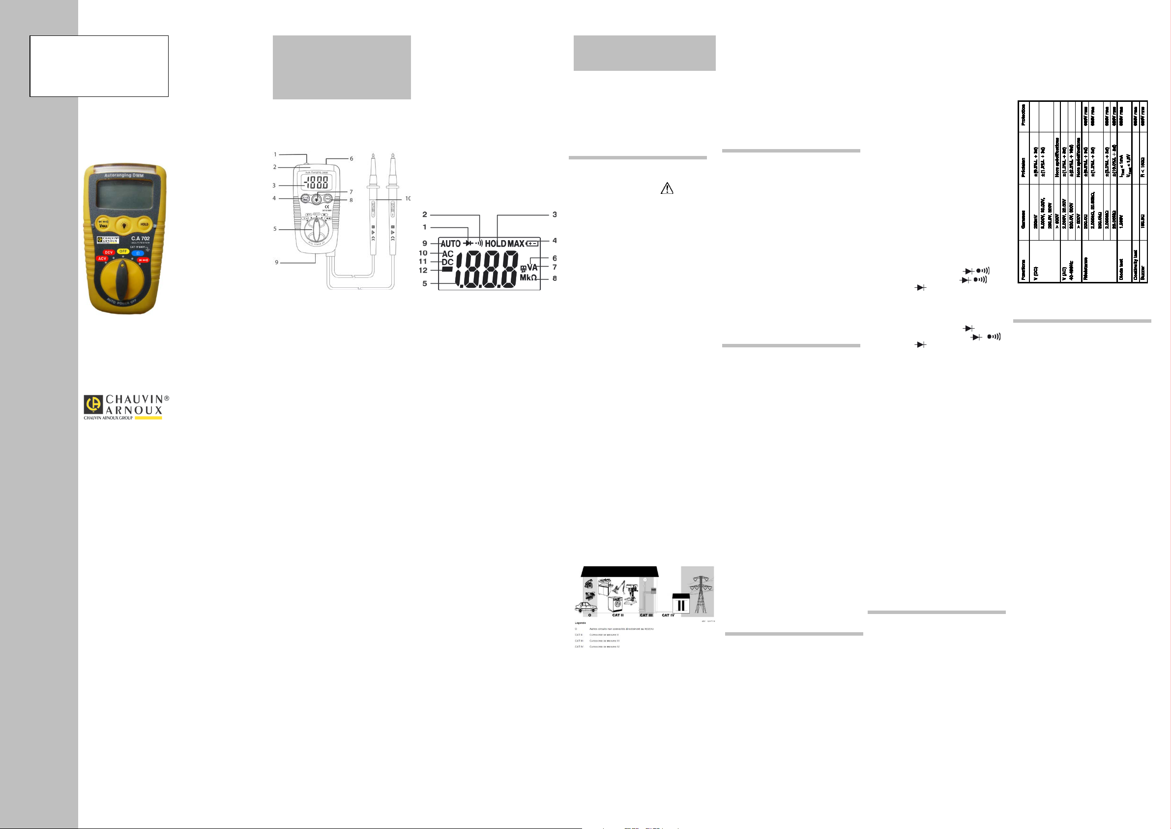
DESCRIPTION
BESCHREIBUNG
DESCRIZIONE
DESCRIPCIÓN
FACE AVANT – FRONT PANEL
FACCIA ANTERIORE - FRONTAL
VORDERSEITE
1. Capteur détection de tension sans contact FR
Contact-free voltage detection sensor GB
Spannungsprüfer berührungslo D
Sensore rilevazione di tensione senza contatto I
Sensor detección de tensión sin contacto E
2. Barre lumineuse d’indication de tension FR
Voltage indication light bar GB
Spannungsanzeige D
Barra luminosa indicante la tensione I
Barra luminosa de indicación de tensión E
3. LCD FR
LCD GB
LCD D
LCD I
LCD E
4. Touche de sélection de mesure FR
Measurement selection key GB
Messwahltaste D
Tasto di selezione di misura I
Tecla de selección de medida E
5. Commutateur FR
Switch GB
Umschalter D
Commutatore I
Conmutador E
6. Torche lumineuse FR
Flashlight GB
Stablampe D
Torcia luminosa I
Torcha luminosa E
7. Touche pour actionner la torche lumineuse FR
Flashlight On key GB
Taste für die Stablampe D
Tasto per azionare la torcia luminosa I
Tecla para accionar la torcha luminosa E
8. Touche HOLD FR
HOLD key GB
Taste HOLD D
Tasto HOLD I
Tecla HOLD E
9. Trappe à piles FR
Battery compartment GB
Batteriefach D
Sportello delle pile I
Tapa de pilas E
10. Pointes de touches solidaires du testeur FR
Probe tips on the tester itself GB
Tastspitzen in Gerät integriert D
Punte di contatto unite al tester I
Puntas solidarias del comprobador E
LCD
1. Diode FR
Diode GB
Diode D
Diodo I
Diodo E
2. Continuité FR
Continuity GB
Durchgang D
Continuità I
Continuidad E
3. Maintien de l’afficheur HOLD FR
Display unit HOLD GB
Hold-Funktion D
Mantenimento del display HOLD I
Fijación del visualizador E
4. Indicateur usure pile FR
Battery low indicator GB
Batteriezustand D
Indicatore usura pila I
Indicador de desgaste de la pila E
5. Valeur mesurée FR
Value measured GB
Messwert D
Valore misurato I
Volor medido E
6. Tension FR
Voltage GB
Spannung D
Tensione I
Tensión E
7. Courant FR
Current GB
Strom D
Corrente I
Corriente E
8. Résistance FR
Resistance GB
Widerstand D
Resistenza I
Resistencia E
9. Gammes automatiques FR
Automatic ranges GB
Automatische Bereiche D
Gamme automatiche I
Gamas automáticas E
10. Alternatif FR
AC GB
WS D
Alternata I
Alterna E
11. Continu FR
DC GB
GS D
Continuita I
Continua E
12. Polarité négative FR
Negative polarity GB
Negative Polarität D
Polarità negativa I
Polaridad negativa E
FRANÇAIS
Félicitations pour l’achat de ce multimètre de poche
numérique.
C’est un appareil d’utilisation simple faisant partie de
la gamme CHAUVIN-ARNOUX permettant d’effectuer
les mesures de grandeurs suivantes
résistance, test de continuité et de diodes.
PRÉCAUTIONS D’EMPLOI
Lis
indications précédées du symbole .
Reportez-vous aux messages de sécurité afin d’éviter
les accidents corporels, tels que les brûlures et chocs
électriques.
NORMES :
Catégorie de surtension IV, Tension max. d’entrée :
600 V.
Attention !
d’Absence de Tension ou un Détecteur de Tension au
sens de l’UTE C18510
CATÉGORIES DE MESURE (IEC 61010-2-033)
Catégorie de mesure II :
La catégorie de mesure II est applicable aux circuits
points d’utilisation (prises de courant et autres points
similaires) du RESEAU basse tension. Au minimum,
deux niveaux de dispositifs de protection contre les
surintensités sont supposés être présents entre le
transformateur et le point de mesure.
Exemple : Les mesures sur les CIRCUITS RESEAU
des appareils électroménagers, des outils portables et
autres appareils similaires.
Catégorie de mesure III :
La catégorie de mesure III est applicable aux circuits
l'installation du RESEAU basse tension du bâtiment.
Au minimum, un niveau de dispositifs de protection
contre les surintensités est supposé être présent entre
le transformateur et le point de mesure.
distribution (y compris les compteurs divisionnaires),
les disjoncteurs, le câblage y compris les câbles, les
barressectionneurs, les prises de courants dans l'installation
fixe, et les appareillages à usage industriel et autres
permanence sur l'installation fixe.
Catégorie de mesure IV :
La catégorie de mesure IV est applicable aux circuits
de test et de mesure connectés à la source de
l'installation du RESEAU basse tension du bâtiment.
dispositifs de protection contre les surintensités entre
le transformateur et le point de mesure.
Exemple : Les mesures sur des dispositifs installés
l'installation du bâtiment.
POUR TRAVAILLER EN SÉCURITÉ :
- Soyez particulièrement vigilants pour des tensions
supérieures à 30VAC RMS et 50VDC.
- Ne travaillez jamais au-delà des plages de tension
max. indiquées.
- Vérifiez l’état de fonctionnement des cordons et de
l’appareil.
- Ne pas utiliser l’appareil si celui-ci est détérioré.
- Connectez en premier la pointe de touche noire, puis
la rouge.
- Déconnectez en premier la pointe de touche rouge,
puis la noire.
- Les doigts ne doivent jamais dépasser la garde.
- Déconnectez
changement de fonction.
- Vérifiez l’absence
fonction continuité, résistance ou test diodes.
- Contrôlez la concordance entre la position du
commutateur et le choix de la fonction.
- N’utilisez jamais le testeur sans gants pour
électriciens et autres équipements de sécurité
préconisés par la législation.
- N’utilisez jamais dans un environnement
humide/poussiéreux.
- Ne changez pas les piles lorsque les cordons
sont connectés.
- Ne démontez pas le boîtier, seule la trappe à
piles peut être ouverte.
Ce matériel est garanti contre tout défaut de
matière ou vice de fabrication, conformément aux
conditions générales de vente. Durant la période
de garantie (1 an), l’appareil ne peut être réparé
que par le constructeur, celui-ci se réservant la
décision de procéder soit à la réparation, soit à
l’échange de tout ou partie de l’appareil.
En cas de retour du matériel au constructeur, le
transport aller est à la charge du client.
La garantie ne s’applique pas suite à :
- une utilisation impropre du matériel ou par
association de celui-ci avec un équipement
incompatible.
- une modification du matériel sans autorisation
explicite des services techniques du constructeur.
- une intervention de réparation effectuée par une
personne non agréée par le constructeur.
- l’adaptation à une application particulière, non
prévue par la définition du matériel ou par la notice
de fonctionnement.
- un choc, une chute ou une inondation
DÉBALLAGE ET RÉ-EMBALLAGE
l’expédition. Toutefois, il est conseillé de procéder
à une vérification rapide pour détecter toute
détérioration éventuelle lors du transport. Si tel
était le cas, faites alors immédiatement les
réserves d’usage auprès du transporteur.
En cas de réexpédition, utilisez l’emballage
d’origine et indiquez, par une note jointe à
l’appareil, les motifs du renvoi.
VÉRIFICATION MÉTROLOGIQUE
Comme tous les appareils de mesure ou d’essais,
une vérification périodique est nécessaire.
Nous vous conseillons une vérification annuelle de
cet appareil. Pour les vérifications et étalonnages,
adressez-vous à nos laboratoires de métrologie
accrédités COFRAC ou aux centres techniques
MANUMESURE.
Renseignements et coordonnées sur demande :
Tél. : 02 31 64 51 55 - Fax : 02 31 64 51 72
ENTRETIEN
Périodiquement, nettoyez votre multimètre avec
un tissu humide imprégné d’eau savonneuse.
N’utilisez pas de matières abrasives ou contenant
des solvants.
STOCKAGE
Si vous n’utilisez pas votre multimètre pendant
une période supérieure à 60 jours, retirez les piles
et stockez-les séparément.
GARANTIE
MAINTENANCE
DESCRIPTION
FONCTIONNELLE
DÉTECTION DE PHASE AC SANS CONTACT
Attention : Testez l’appareil sur le secteur avant
utilisation pour vous assurer du bon état de
fonctionnement de l’appareil.
Cette fonction marche, l’appareil étant éteint ou
allumé et quelque soit la position du commutateur.
- Mettre le capteur de phase AC sans contact
(rep. 1) à proximité immédiate de la prise, du
câble ou du connecteur à tester.
- La barre lumineuse d’indication de tension
(rep.2) s’allume en cas de présence d’une tension
alternative comprise entre 100 et 600VAC par
rapport à la terre.
- Cette fonction permet ainsi de repérer la phase
du neutre.
Attention : la présence champs électrostatiques
(frottement...) peut occasionner l’allumage
intempestif de la barre lumineuse.
De même, la sensibilité de l’appareil en présence
de champs électromagnétiques importants (dans
des armoires électriques par exemple) peut
conduire à un diagnostic erroné de présence de
tension. Pour ces raisons, utilisez un appareil
conforme à la norme IEC 61243-3 pour effectuer
vos opérations de détection de tension, par
exemple le C.A 760.
MESURE DE TENSION ALTERNATIVE OU
CONTINU
- Positionnez le commutateur sur la fonction.
- Appliquez la pointe de touche noire sur un pôle,
puis la pointe de touche rouge sur le second pôle.
Lisez la valeur sur l’afficheur.
Enfin, retirez la pointe de touche rouge, puis la
noire.
MESURE DE RÉSISTANCE « Ω »
- Travaillez hors tension.
- Positionnez le commutateur sur « Ω ».
- Appliquez les pointes de touche rouge et noire sur
l’objet à mesurer.
- Lisez la valeur sur l’afficheur.
Nota : l’appareil est protégé jusqu’à 600VRMS sur
cette entrée.
CONTRÔLE DE CONTINUITÉ
- Travaillez hors tension.
- Positionnez le commutateur sur « ».
- Appuyez successivement sur « V
jusqu’à ce que « » apparaisse.
- Appliquez les pointes de touches rouge et noire
sur le circuit ou le conducteur à mesurer.
TEST DE DIODE
- Travaillez hors tension.
- Positionnez le commutateur sur « ».
- Appuyez successivement sur « »
jusqu’à ce que « » apparaisse.
- Appliquez les pointes de touche rouge et noire sur
le circuit ou le conducteur à mesurer.
FONCTION HOLD
- Connectez les pointes de touche.
- Appuyez sur la touche HOLD pour figer l’écran.
- Le texte « HOLD » apparaît à l’écran et le buzzer
retentit.
- Retirez les pointes de touche.
- Lisez la valeur sur l’afficheur.
FONCTION ÉCLAIRAGE « TORCHE »
LUMINEUSE
Cette fonction marche, l’appareil étant allumé et
éteint, quelque soit la position du commutateur.
- Appuyez et maintenez la touche (rep.7) enfoncée
tant que vous désirez que la torche lumineuse (rep.
6) reste allumée.
AUTO POWER OFF
- Le C.A 702 s’éteint automatiquement 15’ après la
dernière opération.
commutateur repousse ce délai.
REMPLACEMENT DES PILES
Si le symbole «batterie» apparaît, les piles sont trop
faibles. Remplacez-les par deux piles AAA 1.5V :
- Déconnectez les pointes de touche.
- Positionnez le commutateur sur OFF.
- Retirez la vis du volet pile, puis remplacez les
piles et refermez et revissez le couvercle (rep. 9).
»
Max
CARACTÉRISTIQUES
SPÉCIFICATIONS
- Méthodes de mesure : moyenne
- Bande passante : 40-400Hz
- Impédance d’entrée (VAC & DC) : 7.5MΩ
- Afficheur : 1999 points
- Sélection de gammes : automatique
- Dépassement de gammes : affichage «OL» en
résistance.
- Indication de polarité : signe «1»
- Indication d’usure piles: symbole «pile faible»
- Fréquence d’échantillonnage : env.2 fois par s.
- Environnement de travail : 0 à 40°C; RH<80%
absence de condensation.
- Conditions de stockage : -10°C à 50°C; RH<70%,
absence de condensation.
- Alimentation électrique : 2 piles AAA 1.5V.
- Masse : env. 145g.
- Dimensions : 104(L) x 55(l) x 32.5(H)mm
GÉNÉRALES
SPÉCIFICATIONS TECHNIQUES
Métrologie
Conditions de référence : 18°C – 28°C ; RH <
80%, absence de condensation.
Norme : IEC 61010-1
IEC 61010-031
IEC 61010-2-033
POUR COMMANDER
Multitesteur C.A 702 P01191739Z
Livré avec deux cordons solidaires à pointe de
fonctionnement.
Page 2

You have just acquired a Digital Pocket
range of products. This is a simple use
obeyed to avoid accidental burn or electric
utilization points (socket outlets and similar
a minimum of two levels of overcurrent
of household appliances, portable tools and
(including secondary electricity meters),
equipment for
current protective devices between the
Pay special attention when measuring the
on the probe when making
Withdraw the probe tips from the tested
Remove the screw from the battery
with test probes, 2 AAA (1.5V) batteries, and
Beispiel: Messungen an den
und Messkreise, die an der
durchgeführt werden. An diesem
Installationsabschnitt kann keine
vorrichtung zwischen
unseren allgemeinen
ENGLISH
Multimeter.
Congratulations for your choice and thank you
for your trust in the quality of our products. This
instrument belongs to the CHAUVIN ARNOUX
multimeter capable of measuring the following
measurements: voltages, resistance, continuity
and diode.
Before use, carefully read the following safety
precautions.
Instructions followed by the sign must be
shock.
STANDARD :
This device is not a voltage verification device
according to IEC 61243-3 standard.
Overvoltage Category IV, Max. Input Voltage :
600 V
MEASUREMENT CATEGORIES
(IEC 61010-2-033)
Measurement category II :
Measurement category II is applicable to test
and measuring circuits connected directly to
points) of the low-voltage MAINS installation.
This part of the installation is expected to have
protective devices between the transformer and
the connecting points of the measuring circuit.
Example: measurements on MAINS CIRCUITS
similar equipment.
Measurement category III :
Measurement category III is applicable to test
and measuring circuits connected to the
distribution part of the building’s low-voltage
MAINS installation. This part of the installation
is expected to have a minimum of one level of
over-current protective devices between the
transformer and possible connecting points.
Example : measurements on distribution boards
circuitbreakers, wiring, including cables, bus-
bars, junction boxes, switches, socket -outlets
in the fixed installation, and
industrial use and some other equipment such
as stationary motors with permanent connection
to the fixed installation.
Measurement category IV :
Measurement category IV is applicable to test
and measuring circuits connected at the source
of the building’s low-voltage MAINS installation.
This part of the installation could have no over-
transformer and connecting points of the
measuring circuit.
Example : measurements on devices installed
before the main fuse or circuit breaker in the
building installation.
TO WORK SAFETY :
voltage of 30 VAC RMS and 50 VDC.
- Never apply input signals exceeding the
maximum rating input value.
- Always keep your fingers behind the finger
guards
measurement.
- Be sure to disconnect the test pins from the
circuit when changing the function.
- Never use meter if the meter or test leads are
damaged or broken.
- Before performing continuity or resistance
measurement, make sure that no voltage is
present.
PRECAUTIONS FOR USE
- Before starting measurement, make sure that
the function is properly set in accordance with
the measurement.
- Never use without gloves for electricians and
other equipment recommended by the Law.
- Never use in a dusty or wet environment.
- Never replace the batteries without
disconnecting the leads.
- Never open the meter except when replacing
batteries. The one part of the casing which
can be opened is the battery compartment.
The guarantee does not apply in the event of :
- unsuitable use of the equipment or by
association with incompatible equipment.
- modification of the equipment without the
explicit authorization of the manufacturer
technical services.
- a repair done by a person not approved by
the manufacturer.
- adaptation to a specific application not
provided for in the equipment definition or in
the operating instructions impact, fall or
flooding
UNPACKING, RE-PACKING
All equipment has been mechanically and
electrically checked before being dispatched.
However, it is wise to check briefly that
equipment was not damaged during transport.
If so, please contact our.
Marketing Department as soon as possible
and claim carrier legal reserve.
If the equipment is being sent back, please
preferably use original packaging and indicate
as clearly as possible the reasons for sending
it back on a note enclosed with the equipment.
METROLOGICAL VERIFICATION
Return your instrument to your distributor for
any work to be done within or outside the
guarantee.
MAINTENANCE
Use a damp cloth to clean the exeterior
housing, ensure no water or soap is allowed
inside the tester.
STORAGE
If the tester must not be used for periods
longer than 60 days, remove the batteries and
store them separately.
GUARANTEE
MAINTENANCE
FUNCTIONAL
CONTACT-FREE AC PHASIS DETECTION
Attention : Attention : Test the instrument on
line power before use to check that it is in
good working order.
This function works whether the instrument is
Off or On, and whatever the setting of the
switch.
- Place the contact-free AC phasis sensor
(item 1) near the socket, cable, or connector to
be tested.
- The voltage indication light bar (item 2) lights
if an AC voltage between 100 and 600V with
respect to earth is present.
- This function can thus be used to tell the
phase and neutral apart.
Attention : the presence of electrostatic fields
(friction, etc.) may induce untimely lighting of
the light bar.
Likewise, the sensitivity of the instrument in
the presence of strong electromagnetic fields
(e.g. in electrical cabinets) may lead to errored
voltage present indications. We accordingly
recommend using an instrument complying
with standard IEC 61243-3 (e.g. the C.A 760)
for your voltage detection operations.
AC OR DC VOLTAGE MEASUREMENT
- Set the switch to the «V» function.
- Place the black probe tip on one pole, then the
red probe tip on the other pole.
- Read the value on the display unit.
- Finally, withdraw the red probe tip, then the
black probe tip.
DESCRIPTION
RESISTANCE MEASUREMENT « Ω »
- Work with power off.
- Set the switch to « Ω ».
- Place the red and black probe tips on the
object to be measured.
- Read the value on the display unit.
Note : the instrument is protected up to 600V
rms on this input.
CONTINUITY CHECK
- Work in a power-off condition.
- Set the switch to « ».
- Press « V
« Ω » and « » appears.
- Place the red and black probe tips on the
circuit or conductor to be measured.
The beeper sounds if the circuit is closed and
connected.
object.
DIODE TEST
- Work in a power-off condition.
- Set the switch to « ».
- Press « » repeatedly until « »
appears.
- Connect the cords to the diode to be tested.
HOLD FUNCTION
- Connect the probe tips.
- Press the HOLD key to freeze the screen.
- The text « HOLD » appears on the screen and
the buzzer sounds.
- Withdraw the probe tips.
- Read the value on the display unit.
« FLASHLIGHT » FUNCTION
This function works whether the instrument is
Off or On, whatever the setting of the switch.
- Press the key (no.7) and hold it down as long
as you want the flashlight (item 6) to remain lit.
AUTO POWER OFF
- The C.A 702 switches itself off automatically
15’ after the last operation.
- Any action on the HOLD key or the switch
resets the timer.
REPLACING THE BATTERIES
If the « battery » symbol appears, the batteries
are too weak. Replace them with two 1.5V AAA
batteries :
- Disconnect the probe tips.
- Set the switch to OFF.
compartment cover, then replace the batteries,
and close back and screw the cover back down
(item 9).
» repeatedly until
Max
GENERAL
CHARACTERISTICS
SPECIFICATIONS
- Measurement method : mean
- Passband : 40-400Hz
- Input impedance (VAC & DC) : 7.5MΩ
- Display unit : 1,999 points
- Range selection : automatic
- Range overshoot : display «OL» in resistance
mode.
- Polarity indication : «1» sign
- Battery condition indication: «battery low»
symbol
- Sampling frequency : approx. twice per s.
- Operating environment : 0 to 40°C; RH<80%
no condensation.
- Storage condition : -10°C to 50°C; RH<70%,
no condensation.
- Power source : 2 AAA 1.5V batteries.
- Mass : approx. 145g.
- Dimensions : 104(l) x 55(w) x 32.5(h)mm
TECHNICAL SPECIFICATION
Metrology
Reference conditions : 18°C – 28°C ; RH <
80%, no condensation.
Standard : IEC 61010-1
IEC 61010-031
IEC 61010-2-033
C.A 702 Multitester P01191739Z
Delivered with two permanently connected leads
these operating instructions.
TO ORDER
DEUTSCH
Wir beglückwünschen Sie zum Kauf dieses
digitalen.
Taschen-Multimeters. Dieses Multimeter gehört
zur CHAUVIN ARNOUX Geräteserie und verfügt
über die folgenden.
Messfunktionen: Spannungen, Widerstände,
Durchgangsprüfung und Diodentest.
HINWEISE ZUR
Bitte lesen Sie die Sicherheitshinweise vor jeder
Benutzung des Geräts!Bitte beachten Sie die
mit dem Symbol gekennzeichneten
Hinweise besonders sorgfältig.Bitte lesen Sie
die Sicherheitshinweise, um Verletzungen, wie
elektrische Schläge oder Verbrennungen beim
Umgang mit dem Gerät zu vermeiden.
NORMEN :
Dieses Gerät dient nicht zum Nachweis der
Spannungsfreiheit im Sinne der IEC 61243-3.
Überspannungskat. IV, max.
Eingangsspannung: 600V
MESSKATEGORIEN (IEC 61010-2-033)
Messkategorie II :
Die MESSKATEGORIE II b ezieht sich au f Prüfund Messkreise, die direkt an Verbrauchsstellen
(Stecker u.ä) Niederspannungsnetzen
angeschlossen sind. Es sollten mindestens zwei
Stufen Überstromschutzvorrichtungen zwischen
Transformator und Messpunkt vorhanden sein.
NETZVERTEILERN von Haushaltsgeräten,
tragbaren Elektrogeräten und ähnlichen
Geräten.
Messkategorie III :
Die MESSKATEGORIE III bezieht sich auf Prüf-
Niederspannungsinstallation des Gebäudes
durchgeführt werden. Es sollte mindestens eine
Stufe Überstromschutzvorrichtungen zwischen
Transformator und Messpunkt vorhanden sein.
Beispiel: Messungen am Verteileranschluss,
Energiezähler, Schutzschalter, Verkabelung mit
Kabeln, Bus, Unterverteilung, Trennschaltern,
Stecker an der Installation, sowie
Industriegeräte und Ausrüstungen wie fest an
die Installation angeschlossene Motoren.
Messkategorie IV :
Die Messkategorie IV bezieht sich auf Prüf- und
Messkreise, die an der Quelle der
Niederspannungsinstallation des Gebäudes
Überstromschutz
Transformator und Messpunkt vorhanden sein.
Beispiel: Schutzeinrichtungen vor dem
Hauptschutzschalter bzw. der Trennvorrichtung
der Gebäudeinstallation.
SICHERES ARBEITEN :
- Seien Sie besonders vorsichtig beim Umgang
mit Spannungen über 30 VAC RMS oder 50
VDC.
- Arbeiten Sie niemals an Spannungen über der
angegebenen maximal zulässigen
Eingangsspannung (600 V gegenüber Erde).
- Prüfen Sie vor jeder Messung den Zustand der
Messleitungen und des Geräts.
- Benutzen Sie niemals ein beschädigtes Gerät.
- Greifen Sie die Messgröße immer zuerst mit
der schwarzen Prüfspitze ab und erst danach
mit der roten.
- Entfernen Sie immer zuerst die rote Prüfspitze
vom Messpunkt und erst danach die schwarze.
BENUTZUNG
- F assen S ie die Prüfspitzen immer hinter dem
Griffschutz an.
- Entfernen Sie die Prüfspitzen vor jedem
Wechsel der Messfunktion von einem
Messpunkt.
- Prüfen Sie vor Benutzung der Messfunktionen
W oder ob die Schaltung spannungsfrei ist.
- Vergewissern Sie sich, dass der
Funktionsdrehschalter auf der gewünschten
Messart steht.
- Benutzen Sie das Gerät niemals ohne die
vorgeschriebenen Sicherheitsausrüstungen
(z.B. Elektriker-Handschuhe…).
- Benutzen Sie das Gerät niemals in feuchter
und/oder staubiger Umgebung.
- Entfernen Sie vor jedem Batterie-wechsel die
Prüfspitzen von einem Messpunkt.
- Versuchen Sie niemals das Gehäuse zu
öffnen. Lediglich das Batteriefach darf vom
Benutzer geöffnet werden.
Dieses Gerät unterliegt einer Garantie gegen
Werkstoff- und Herstellungsmängel
entsprechend
Verkaufsbedingungen.
Während der Garantiefrist von 1 Jahr darf das
Gerät nur vom Hersteller repariert werden,
wobei sich dieser das Recht vorbehält, das
Gerät instand zu setzen oder es ganz oder
teilweise auszutauschen.
Die Kosten für die Rücksendung des Geräts
zum Hersteller gehen zu Lasten des Käufers.
Die Garantieleistung ist in folgenden Fällen
ausgeschlossen
1. Bei unsachgemäßer Verwendung des Geräts
oder seiner Verwendung in Verbindung mit
unkompatiblen anderen Geräten.
2. ei Eingriffen oder Änderungen am Gerät, die
ohne ausdrückliche Zustimmung des
Herstellers vorgenommen wurden.
3. Reparaturarbeiten durch nicht vom Hersteller
zugelassene Personen.
4. Bei Anpassungen des Geräts an
Anwendungen, für die es laut Definition oder
Hinweisen in der Bedienungsanleitung nicht
vorgesehen ist.
5. Bei Schäden durch Schlag-, Stoß-, Sturzoder Wassereinwirkung
VERPACKUNG
Das vollständige Geräte wurde vor dem
Versand mechanisch und elektrisch geprüft. Bei
Erhalt des Geräts empfiehlt es sich, es sofort
auf eventuelle Transportschäden zu prüfen.
Melden Sie solche Transportschäden
unverzüglich dem Zusteller bzw. Spediteur und
nehmen Sie die Lieferung nur unter Vorbehalt
an. Verwenden Sie für die Rücksendung des
Geräts immer die Originalverpackung und legen
Sie eine Notiz mit dem Grund für die
Rücksendung bei.
MESSTECHNISCHE ÜBERPRÜFUNG
Wie auch bei anderen Mess- oder Prüfgeräten
ist eine regelmäßige Geräteüberprüfung
erforderlich.
Es wird mindestens eine einmal jährlich
durchgeführte Überprüfung dieses Gerätes
empfohlen. Für Überprüfung und Kalibrierung
wenden Sie sich bitte an unsere zugelassenen
Messlabors (Auskunft und Adressen auf
Anfrage), bzw. an die Chauvin Arnoux
Niederlassung oder den Händler in Ihrem Land.
REINIGUNG
Reinigen Sie Ihr Multimeter regelmäßig mit
einem leicht mit Seifenlauge angefeuchteten,
weichen Tuch.
Verwenden Sie dazu niemals Scheuermittel
oder lösungsmittelhaltige Reiniger.
AUFBEWAHRUNG
Wenn Sie Ihr Multimeter für längere Zeit nicht
benutzen (2 Monate oder mehr) sollten Sie die
Batterien herausnehmen und separat lagern.
GARANTIE
WARTUNG
FUNKTIONS-
BESCHREIBUNG
AC-SPANNUNGSPRÜFUNG,
BERÜHRUNGSLOS
Achtung : Das Gerät vor dem Gebrauch am
Stromnetz auf Einwandfreiheit testen.
Diese Funktion ist sowohl bei ein- als auch bei
ausgeschaltetem Gerät und bei beliebiger
Umschalterstellung vorhanden.
- Den AC Spannungsprüfer (Mark. 1) direkte
Nähe des gewünschten Steckers, Kabels oder
Anschlusses bringen.
- Die Spannungsanzeige (Mark. 2) leuchtet auf,
wenn Wechselspannung zwischen 100 und
600V AC gegenüber Erde vorhanden ist.
- Mit dieser Funktion wird auch die Neutralphase
erkannt.
Achtung : Elektrostatische Felder (Reibung
u.ä.) kann dazu führen, dass die
Spannungsanzeige unbegründet aufleuchtet.
Die Empfindlichkeit des Prüfers kann
gleichermaßen dazu führen, dass bei starken
elektromagnetischen Feldern (z.B. in
Schaltkästen) die Spannungsanzeige fehlerhaft
sein kann.
In diesem Fall verwenden Sie ein IEC 61243-3
normgerechtes Gerät für die Spannungsprüfung
wie zum Beispiel den C.A 760.
PRÜFEN DER WECHSEL- ODER
GLEICHSPANNUNG
- Den Umschalter auf «V» stellen.
- Die schwarze Tastspitze auf einen Pol, dann
die rote Tastspitze an den zweiten Pol anlegen.
- Anzeigenwert ablesen.
- Z uerst die rote, dann die schwarze Tastspitze
abnehmen.
WIDERSTANDSPRÜFUNG « Ω »
- In spannungslosem Zustand arbeiten.
- Den Umschalter auf « Ω » stellen.
- Die rote und die schwarze Tastspitze an den
gewünschten Gegenstand anlegen.
- Anzeigewert ablesen.
Hinweis : An diesem Eingang ist das Gerät bis
zu 600V rms geschützt.
DURCHGANGSPRÜFUNG
- In spannungslosem Zustand arbeiten.
- Den Umschalter auf « » stellen.
- « V
« Ω » und « » erscheint.
- Die rote und die schwarze Tastspitze an den
gewünschten Leiter oder Kreis anlegen.
Der Summer ertönt, wenn der Kreis
geschlossen und angeschlossen ist.
- Die Tastspitzen vom geprüften Gegenstand
entfernen.
DIODENTEST
- In spannungslosem Zustand arbeiten.
- Den Umschalter auf « » stellen.
- « » solange betätigen, bis « »
erscheint.
- Die Leitungen an die gewünschte Diode
anschließen.
HOLD-FUNKTION
- Tastspitzen anschließen.
- Mit der Hold-Taste den Bildschirm einfrieren.
- Auf dem Bildschirm erscheint HOLD und der
Summer ertönt.
- Tastspitzen entfernen.
- Anzeigewert ablesen.
BELEUCHTUNG MIT “STABLAMPE”
- Diese Funktion ist sowohl bei ein- als auch bei
ausgeschaltetem Gerät und bei beliebiger
Umschalterstellung vorhanden.
- Die Taste (Mark. 7) solange gedrückt halten,
wie die Stablampe (Mark. 6) aufleuchten soll.
AUTO POWER OFF
- Der DMM scha ltet sich automatisch 15’ nach
dem letzen Einsatz ab.
- Wenn die Hold-Taste oder der Umschalter
betätigt werden, wird das Abschalten verzögert.
BATTERIEWECHSEL
Wenn das Symbol „Batterie“ erscheint, sind die
Batterien zu schwach und müssen mi t zwei AAA
1.5V Batterien ausgewechselt werden:
- Tastspitzen abnehmen.
- Umschalter auf OFF stellen.
- Schraube aus der Batterieabdeckung
entfernen, Batterien wechseln und Deckel
wieder zuschrauben (Mark. 9).
» solange betätigen, bis
Max
ALLGEMEINE
EIGENSCHAFTEN
SPEZIFIKATIONEN
- Messverfahren: mittel
- Bandbreite: 40 – 400 Hz
- Eingangsimpedanz (V AC& DC): 7.5 Mohm
- Anzeige: 1999 Digits
- Bereichsauswahl: automatisch
- Bereichsüberschreitung: Anzeige „OL“ bei
Widerstand
- Polanzeige: Zeichen „-„
- Batteriezustandsanzeige: Symbol „schwache
Batterie“
- Abtastfrequenz: ca. 2 Mal pro S.
- Arbeitsbedingungen: 0 bis 40°C; RH < 80%,
keine Kondensation
- Aufbewahrung: -10°C bis 50°C; RH < 70%,
keine Kondensation
- Stromversorgung: 2 Batterien AAA 1.5V
- Gewicht: ca. 145 g
- Abmessungen: 104 (L) x 55 (B) x 32.5(H) mm
TECHNISCHE EIGENSCHAFTEN
Messeigenschaften
Messbedingungen : 18°C – 28°C ; RH < 80%,
Keine Kondensation.
Norm : IEC 61010-1
IEC 61010-031
IEC 61010-2-033
BESTELLANGABEN
MULTIPRÜFER C.A 702 P01191739Z
Lieferung mit zwei verbundenen Leitungen mit
Prüfspitzen, 2 Batterien 1.5V AAA und dieser
Bedienungsanleitung.
Page 3

Complimenti per l’acquisto del presente
ARNOUX e che permette di
Leggere le seguenti istruzioni di sicurezza
Rilevatore di
Cat. di sovratensione IV, Tensione max.
protezione contro le sovraintensità fra il
RETE a bassa tensione
ripartizione), i
prese di corrente nell'impianto fisso, e le
apparecchiature per uso industriale e altri
equipaggiamenti come i motori collegati in
dell'impianto della RETE a bassa tensione
dell’edificio. Questa parte dell'impianto può
monte del fusibile principale o il disgiuntore
Siate particolarmente vigilanti per delle
Scollegare per primo il puntale di contatto
I nottolini non devono mai superare la
Scollegare i cavi prima di cambiare la
Verificare l’assenza di tensione prima di
altre apparecchiature di sicurezza
Non utilizzare mai in ambiente umido /
Il presente materiale è garantito contro
conformemente alle
una modifica del materiale senza
l’adattamento ad una applicazione
Tutto il materiale è stato verificato
allegata all’apparecchio, i motivi della
dello strumento. Per le verifiche e le
Non utilizzare dei materiali abrasivi o
RIVELAZIONE DI FASE AC SENZA
la presenza di campi
l’accensione intempestiva della barra
una diagnostica errata di presenza di
Il beeper squilla se il circuito è chiuso e
FUNZIONE ILLUMINAZIONE “TORCIA”
FUNCIÓN ALUMBRADO „TORCHA“
ITALIANO
multimetro tascabile digitale. E’ un apparecchio
di facile utilizzazione, che fa parte della gamma
CHAUVIN
realizzare le seguenti misure di grandezza :
tensioni, resistenza, test continuità e diodo.
prima di utilizzare l’apparecchio. E’ imperativo
seguire le indicazioni precedute dal
simbolo .
Fare riferimento ai messaggi di sicurezza per
evitare degli eventuali incidenti corporei, quali le
bruciature e gli shock elettrici
NORMA :
Il presente apparecchio non è un Verificatore di
Assenza di Tensione o un
Tensione conformemente all’IEC 61243-3.
d’entrata : 600V
CATEGORIE DI MISURA (IEC 61010-2-033)
Categoria di misura II :
La CATEGORIA DI MISURA II è applicabile ai
circuiti di test e di misura collegati direttamente
ai punti d’utilizzo (prese di corrente e altri punti
affini) della RETE a bassa tensione. Si suppone
la presenza di almeno due livelli di dispositivi di
trasformatore e il punto di misura.
Esempio: Le misure sui CIRCUITI RETE degli
elettrodomestici, degli strumenti portatili e altri
strumenti affini.
Categoria di misura III :
La CATEGORIA DI MISURA III è applicabile ai
circuiti di test e di misura collegati alle parti
dell'impianto della
dell’edificio. Si suppone la presenza di almeno
un livello di dispositivi di protezione contro le
sovraintensità fra il trasformatore e il punto di
misura.
Esempio: Le misure sui quadri di distribuzione
(compresi i contatori di
disgiuntori, il cablaggio (compresi i cavi) le busbar, le scatole di derivazione, i sezionatori, le
permanenza sull'impianto fisso.
Categoria di misura IV :
La CATEGORIA DI MISURA IV è applicabile ai
circuiti di test e di misura collegati alla sorgente
essere sprovvista di dispositivi di protezione
contro le sovraintensità fra il trasformatore e il
punto di misura.
Esempio: Le misure su dispositivi installati a
dell'impianto dell’edificio.
PER LAVORARE IN ASSOLUTA
SICUREZZA :
tensioni superiori a 30 VAC RMS e 50 VDC.
- Mai lavorare al di là delle fasce di tensione
massime indicate (600 V in rapporto alla terra).
- Verificare lo stato di funzionamento dei cavi e
dell’apparecchio.
- Non utilizzare l’apparecchio se risulta
danneggiato.
- Collegare per primo il puntale di contatto nero,
poi quello rosso.
rosso, poi quello nero.
protezione.
funzione.
PRECAUZIONI D’USO
utilizzare la funzione continuità o &.
- Controllare la concordanza fra la posizione del
commutatore e la scelta della funzione.
- Non utilizzare mai senza guanti per elettricisti
ed
raccomandate dalla legislazione.
polveroso.
- Non sostituire le pile quando i cavi sono
collegati.
- Non smontare la scatola, solo lo sportello dal
vano pile può essere aperto.
qualsiasi eventuale difetto di materiale o vizio
di fabbricazione,
condizioni generali di vendita.
Durante il periodo di garanzia (1 anno), lo
strumento può essere riparato solo dal
costruttore, e questi si riserva la decisione di
procedere alla riparazione o alla permuta
dell’apparecchio, o di una sua parte. In caso di
ritorno del materiale al costruttore, il costo
della spedizione d’andata è a carico del
cliente.
La garanzia non si applica a seguito di :
- utilizzazione impropria del materiale o di
associazione di questi con un attrezzatura non
compatibile.
autorizzazione esplicita dei servizi tecnici del
costruttore.
- un intervento di riparazione effettuato da una
persona non autorizzata dal costruttore.
particolare, non prevista dalla definizione del
materiale o del libretto di funzionamento.
- uno shock, una caduta o una inondazione
DISIMBALLAGGIO E REIMBALLAGGIO
meccanicamente ed elettricamente prima della
spedizione. Si consiglia di procedere a verifica
rapida per rilevare qualsiasi eventuale
deterioramento durante il trasporto. Se tale
dovesse essere il caso, presenta allora
immediatamente le riserve d’uso presso il
trasportatore. In caso di rispedizione, utilizza
l’imballaggio d’origine ed indica, con una nota
spedizione.
VERIFIC A METROLOGIC A
Per tutti gli strumenti di misura e di test, è
necessaria una verifica periodica.
Vi consigliamo almeno una verifica annuale
calibrazioni, rivolgetevi ai nostri laboratori di
metrologia accreditati (informazioni e recapiti
su richiesta), alla filiale Chauvin Arnoux del
Vostro paese o al vostro agente.
MANUTENZIONE
Periodicamente, pulire il multimetro con un
panno umido impregnato di acqua e sapone.
contenenti dei solventi.
MAGAZZINAGGIO
Se non utilizzate il multimetro per un periodo
superiore a 60 giorni, togliete le pile e
conservatele separatamente.
GARANZIA
MANUTENZIONE
DESCRIZIONE
CONTATTO
Attenzione : testate l’apparecchio sulla rete
prima
dell’utilizzo per accertarvi del suo corretto
stato di funzionamento.
La funzione è possibile che l’apparecchio sia
spento o acceso e qualunque sia la posizione
del commutatore.
- Mettere il sensore di fase AC senza contatto
(riferimento 1), immediatamente vicino alla
presa, al cavo o al connettore da testare.
- La barra luminosa indicante la tensione
(riferimento 2) si accende in caso di presenza
d’una tensione alternata compresa fra 100 e
600V AC rispetto alla terra.
- Questa funzione permette quindi di reperire
la fase del neutro.
FUNZIONALE
Attenzione :
elettrostatici (sfregamento..) può occasionare
luminosa.
Parimenti, la sensibilità dell’apparecchio in
presenza di forti campi elettromagnetici (nei
quadri elettrici per esempio) può condurre ad
tensione. Per queste ragioni, utilizzate un
apparecchio conforme alla norma IEC 612433 per effettuare le vostre operazioni di
rivelazione di tensione, per esempio il C.A
760.
MISURA DI TENSIONE ALTERNATA O
CONTINUATA
- Posizionate il commutatore sulla funzione “V”.
- Applicate la punta di contatto nera su un polo,
poi la punta di contatto rossa sul secondo polo.
- Leggete il valore sul display.
- Infine, rimuovete la punta di contatto rossa,
poi la nera.
MISURA DI RESISTENZA « Ω »
- Lavorate fuori tensione.
- Posizionate il commutatore su “Ω”.
- Applicate le punte di contatto rossa e nera
sull’oggetto da misurare.
- Leggete il valore sul display.
Nota: l’apparecchio è protetto fino a 600V rms
su questa entrata.
CONTROLLO DI CONTINUITÀ
- Lavorate fuori tensione.
- Posizionate il commutatore su « ».
- Premete successivamente il tasto «
V
» fino a quando « Ω » e « »
Max
apparirà.
- Applicate le punte di contatto rossa e nera sul
circuito o il conduttore da misurare.
collegato.
- Rimuovete le punte di contatto dall’oggetto
testato.
TEST DI DIODO
- Lavorate fuori tensione.
- Posizionate il commutatore su « ».
- Premete successivamente il tasto «
» fino a quando « » apparirà.
- Collegate I fili al diodo da testare.
FUNZIONE HOLD
- Collegate le punte di contatto.
- Premete il tasto HOLD per congelare lo
schermo.
- Il testo « HOLD » appare sullo schermo e il
buzzer squilla.
- Rimuovete le punte di contatto.
- Leggete il valore sul display.
LUMINOSA
La funzione è possibile che l’apparecchio sia
spento o acceso e qualunque sia la posizione
del commutatore.
- Premete e mantenete il tasto (riferimento 7)
premuto finché volete che la torcia luminosa
(riferimento 6) rimanga accesa.
AUTO POWER OFF
- C.A 702 si spegne automaticamente 15’ dopo
l’ultima operazione.
- Qualsiasi azione sul tasto HOLD o sul
commutatore rinvia questo termine.
SOSTITUZIONE DELLE PILE
Se appare il simbolo “batteria”, le pile sono
troppo deboli. Sostituitele con due pile AAA
1.5V:
- Disinserite le punte di contatto.
- Posizionate il commutatore su OFF
- Rimuovete la vite dello sportello delle pile,
sostituite le pile, richiudete e riavvitate il
coperchio (riferimento 9).
CARATTERISTICHE
SPECIFICHE
- Metodo di misura: medio
- Banda passante: 40 – 400 Hz
- Impedenza d’entrata (V AC& DC): 7.5 Mohms
- Display: 1999 punti
- Selezione di gamme: automatica
- Superamento di gamme: display “OL” in
resistenza
- Indicazione di polarità: segno “-“
- Indicazione d’usura delle pile: simbolo “pila
debole”
- Frequenza di campionatura: circa 2 volte / s.
- Ambiente di lavoro: da 0 a 40°C; UR < 80%,
assenza di condensazione
- Condizioni di stoccaggio: da -10°C a 50°C;
UR < 70%, assenza di condensazione
- Alimentazione elettrica: 2 pile AAA 1.5V
- Massa: circa 145 g
- Dimensioni: 104 (L) x 55 (l) x 32.5(H) mm
SPECIFICHE TECNICHE
Metrologia
Condizioni di riferimento : 18°C – 28°C ;
RH < 80%, assenza di condensazione.
Norma : IEC 61010-1
IEC 61010-031
IEC 61010-2-033
Multitester C.A 702 P01191739Z
Fornito con due cavi solidali a punte di contatto,
2 pile 1.5V AAA e il presente manuale d’uso.
GENERALI
PER ORDINARE
ESPAÑOL
Felicitaciones por la compra de este e
multímetro de bolsillo digital.Es un aparato de
utilización sencilla, que forma parte de la gama
CHAUVIN ARNOUX que permite efectuar
mediciones de las siguientes magnitudes:
tensiones, resistencia, prueba de continuidad y
diodo.
PRECAUCIONES DE
Leer las siguientes instrucciones de seguridad
antes de utilizar el aparato. Es obligatorio seguir
las indicaciones precedidas por el símbolo .
Remitirse a los mensajes de seguridad para
evitar accidentes corporales como quemaduras
e impactos eléctricos.
NORMA :
Este aparato no es un Verificador de Ausencia
de Tensión o un Detector de Tensión en el
sentido del IEC 61243-3.
CAT. de sobretensión IV, Tensión máx. de
entrada : 600V
CATEGORÍAS DE MEDIDA (IEC 61010-2-033)
Categoría de medida II :
La CATEGORÍA DE MEDIDA II se aplica a los
circuitos de prueba y medida conectados en
forma directa a los puntos de uso (tomas de
corriente y otros puntos similares) de la RED de
baja tensión. Se supone que tiene que haber al
menos dos niveles de dispositivos de protección
contra las sobreintensidades entre el
transformador y el punto de medida.
Ejemplo: Las medidas en los CIRCUITOS DE
RED de electrodomésticos, herramientas
portátiles y demás instrumentos similares.
Categoría de medida III :
La CATEGORÍA DE MEDIDA III se aplica a los
circuitos de prueba y medida conectados a las
partes de la instalación de la RED de baja
tensión del edificio. Se supone que tiene que
haber al menos un nivel de dispositivos de
protección contra las sobre intensidades entre el
transformador y el punto de medida.
Ejemplo: Las medidas en los cuadros de
distribución (incluso los subcontadores),
disyuntores, el cableado e incluso los cables,
las barras-bus, las cajas de derivación, los
seccionadores, las tomas de corriente en la
instalación fija, y los equipos eléctricos de uso
industrial y demás equipos tales como los
motores conectados de forma permanente a la
instalación fija.
Categoría de medida IV :
La CATEGORÍA DE MEDIDA IV se aplica a los
circuitos de prueba y medida conectados a la
fuente de la instalación de la RED de baja
tensión del edificio. Este parte de la instalación
puede no tener dispositivos de protección contra
las sobre intensidades entre el transformador y
el punto de medida.
Ejemplo: Las medidas en dispositivos instalados
antes del fusible principal o del disyuntor de la
instalación del edificio.
PARA TRABAJAR CON SEGURIDAD :
- Sean particularmente vigilantes con las
tensiones superiores a 30 VCA RMS y 50 VCD.
- Nunca trabajar las zonas de tensión máx.
Indicadas (600V respecto a la tierra).
- Verificar el estado de funcionamiento de los
cordones y del aparato.
- No utilizar el aparato si está deteriorado.
- Conectar en primer lugar la punta de prueba
negra, después la roja.
- Desconectar en primer lugar la punta de
prueba roja, después la negra.
- Los pasadores nunca deben exceder la
guarda.
- Desconectar los cordones antes de cambiar de
función.
EMPLEO
- Verificar la ausencia de tensión antes de
utilizar la función continuidad.
- Controlar la concordancia entre la posición del
conmutador y la selección de la función.
- Nunca utilizar sin guantes para electricistas y
otros equipos de seguridad recomendados por
la legislación.
- Nunca utilizar en un entorno
húmedo/polvoriento.
- No cambiar las pilas cuando los cordones
están conectados.
- No desmontar la caja, solamente puede
abrirse la trampilla para pilas.
Este material está garantizado contra todo
defecto de material o vicio de fabricación, de
conformidad con las condiciones generales de
venta. Durante el periodo de garantía (1 año),
el aparato sólo puede repararse por el
constructor, éste se reserva la decisión de
proceder a la reparación o al cambio de todo o
parte del aparato. En caso de devolución del
material al constructor, el transporte de idea
corre a cargo del cliente.
La garantía no se aplica como resultado de :
- una utilización impropia del material o por
asociación de éste con un equipo incompatible
- una modificación del material sin la
autorización explícita de los servicios técnicos
del constructor.
- una actuación de reparación efectuada por
una persona no autorizada por el constructor.
- la adaptación a una aplicación particular, no
prevista por la definición del material o por la
instrucción de funcionamiento un golpe,
- caída o inundación.
DESEMBALJE Y REEMBALAJE
Todo el material ha sido verificado mecánica y
eléctricamente antes de su expedición. No
obstante, e aconseja proceder a una
verificación rápida para detectar cualquier
deterioro eventual producido durante el
transporte.
Si éste fuera el caso, haga de inmediato las
reservas usuales ante el transportista. En caso
de reexpedición, utilice el embalaje original e
indique, mediante una nota adjunta al aparato,
los motivos de la devolución.
VERIFIC AC IÓ N ME TRÓLOGICA
Al igual que todos los instrumentos de medida
o de prueba, es necesario realizar una
verificación periódica.
Le aconsejamos por lo menos una verificación
anual de este instrumento. Para las
verificaciones y calibraciones, póngase en
contacto con nuestros laboratorios de
metrología acreditados (solicítenos información
y datos), con la filial Chauvin Arnoux o con el
agente de su país.
LIMPIEZA
Limpiar con periodicidad su multímetro con un
paño impregnado en agua jabonosa. No utilizar
materiales abrasivos o que contengan
solventes.
ALMACENAMIENTO
Si no utiliza su multímetro durante un periodo
de más de 60 días, retire las pilas y
almacénelas por separado.
GARANTÍA
MANTENIMIENTO
DESCRIPCIÓN
DETECCIÓN DE FASE AC SIN CONTACTO
Atención: Compruebe el aparato en la red
antes de utilizar para asegurarse del buen
estado de funcionamiento del aparato.
Esta función funciona, estando el aparato
apagado o encendido y cualquiera que sea la
posición del conmutador.
- Poner el sensor de fase AC sin contacto
(marca 1) cerca de la toma, del cable o del
conector a probar.
- La barra luminosa de indicación de tensión
(marca 2) se enciende en caso de presencia de
una tensión alterna incluida entre 100 y 600V
AC con respecto a la tierra.
- Esta función permite así identificar la fase del
neutro.
FUNCIONAL
Atención: la presencia de campos
electroestáticos (frotamiento...) puede producir
el encendido intempestivo de la barra luminosa.
Asimismo, la sensibilidad del aparato en
presencia de campos electromagnéticos
importantes (en armarios eléctricos por ejemplo)
puede conducir a un diagnóstico erróneo de
presencia de tensión. Por estas razones, utilizar
un aparato conforme con la norma IEC 61243-3
para efectuar sus operaciones de detección de
tensión, por ejemplo el C.A 760.
MEDIDA DE TENSIÓN ALTERNA O
CONTINUA
- Posicione el conmutador sobre la función “V”.
- Aplique la punta de prueba negra sobre un
polo, luego la punta de prueba roja sobre el
segundo polo.
- Lea el valor en la pantalla.
- Por último, retire la punta de prueba roja, luego
la negra.
MEDIDA DE RESIST ENCIA « Ω »
- Trabaja fiera de tensión.
- Posicione el conmutador sobre « Ω ».
- Aplique las puntas de prueba roja y negra
sobre el objeto a medir.
- Lea el valor en la pantalla.
Nota: el aparato està protegido hasta 600V rms
en esta entrada.
CONTROL DE CONTINUIDAD
- Trabaje fuera de tensión.
- Posicione el conmutador sobre « ».
- Pulse sucesivamente« V
que aparezca « Ω » y « ».
- Aplique las puntas de prueba roja y negra
sobre el circuito o el conductor a medir.
Se escucha un bip si el circuito está cerrado y
conectado.
- Retire las puntas del objeto probado.
TEST DE DIODO
- Trabaje fuera de tensión.
- Posicione el conmutador sobre « ».
- Pulse sucesivamente« » hasta que
aparezca « ».
- Conecte los cables al diodo a probar.
FUNCIÓN HOLD
- Conecte las puntas de prueba.
- Pulse la tecla HOLD para fijar la pantalla.
- El texto “HOLD” aparece en la pantalla y se
escucha el buzzer.
- Retire las puntas de prueba.
- Lea el valor en la pantalla.
LUMINOSA
Esta función funciona, estando el aparato
apagado o
encendido y cualquiera que sea la posición del
conmutador.
- pulse y mantenga la tecla (marca 7) pulsando
mientras se desea que la torcha luminosa
(marca 6) permanezca encendida.
AUTO POWER OFF
- El C.A 702 se apaga automáticamente 15’
después de la última operación.
- Cualquier acción sobre la tecla HOLD o el
conmutador aplaza este tiempo.
SUSTITUCIÓN DE LAS PILAS
Si aparece el símbolo “batería”, las pilas son
demasiado débiles. Reemplácelos por dos pilas
AAA 1.5V:
- Desconecte las puntas de prueba.
- Posicione el conmutador sobre OFF
- Retire el tornillo de la tapa de pilas, luego
reemplace las pilas y cerrar y volver a enroscar
la tapa (marca 9).
» hasta
Max
CARACTERÍSTICAS
ESPECIFICACIONES
- Método de medida: media
- Ancho de banda: 40 – 400 Hz
- Impedancia de entrada (V AC& DC): 7.5
Mohmios
- Pantalla: 1999 puntos
- Selección de gamas: automática
- Rebasamiento de gamas: visualización “OL”
en resistencia.
- Indicación de polaridad: signo “-“
- Indicación de desgaste de pilas: símbolo “pila
débil”.
- Frecuencia de muestreo: aproximadamente 2
veces por s.
- Entorno de trabajo: 0 a 40°C; HR< 80%,
ausencia de condensación.
- Condiciones de almacenamiento: -10°C a
50°C; HR < 70%, ausencia de condensación.
- Alimentación eléctrica: 2 pilas AAA 1.5V
- Masa: aprox. 145 g
- Dimensiones: 104 (L) x 55 (l) x 32.5(H) mm
ESPECIFICACIONES TÉCNICAS
Metrología
Condiciones de referencia: 18°C - 28°C; HR <
80% ausencia de condensación
Norma : IEC 61010-1
IEC 61010-031
IEC 61010-2-033
Multicomprobador C.A 702 P01191739Z
Suministrado con dos cables solidarios con
punta de prueba, 2 pilas 1.5V AAA y este anual
de instrucciones.
GENERALES
PARA PEDIDOS
 Loading...