

Page 1

DÉTECTEUR DE TENSION
VOLTAGE DETECTOR
SPANNUNGSPRÜFER
RIVELATORE DI TENSIONE
DETECTOR DE TENSIÓN
C.A 760N
C.A 760N IP2X
FRANÇAIS
ENGLISH
DEUTSCH
ITALIANO
ESPAÑOL
Notice de fonctionnement
User's manual
Bedienungsanleitung
Manuale d’uso
Manual de instrucciones
Page 2

English ............................................... 22
Deutsch ............................................. 40
Italiano ............................................... 58
Español ............................................. 76
Vous venez d’acquérir un détecteur de tension C.A 760N ou
C.A 760N IP2X et nous vous remercions de votre confiance.
Pour obtenir le meilleur service de votre appareil :
lisez attentivement cette notice de fonctionnement,
respectez les précautions d’emploi.
ATTENTION, risque de DANGER ! L’opérateur
doit consulter la présente notice à chaque fois
que ce symbole de danger est rencontré.
Appareil protégé par une isolation double.
Matériel approprié aux travaux sous tension.
Pile.
Terre.
Le marquage CE indique la conformité aux directives européennes, notamment DBT et CEM.
La poubelle barrée signifie que, dans l’Union
Européenne, le produit fait l’objet d’une collecte
sélective conformément à la directive DEEE
2002/96/EC : ce matériel ne doit pas être traité
comme un déchet ménager.
Définition des catégories de mesure :
La catégorie de mesure IV correspond aux mesurages
réalisés à la source de l’installation basse tension.
Exemple : arrivée d’énergie, compteurs et dispositifs de
protection.
La catégorie de mesure III correspond aux mesurages
réalisés dans l’installation du bâtiment.
Exemple : tableau de distribution, disjoncteurs, machines
ou appareils industriels fixes.
La catégorie de mesure II correspond aux mesurages
réalisés sur les circuits directement branchés à l’installation
basse tension.
Exemple : alimentation d’appareils électrodomestiques
et d’outillage portable.
2
Page 3

PRÉCAUTIONS D’EMPLOI
Cet appareil est protégé contre des tensions n’excédant pas
600 V par rapport à la terre en catégorie de mesure IV.
La protection assurée par l’appareil peut-être compromise si
celui-ci est utilisé de façon non spécifiée par le constructeur
et mettre ainsi l’utilisateur en danger.
Respectez la tension et l’intensité maximales assignées et
la catégorie de mesure. N’utilisez pas votre appareil sur des
réseaux dont la tension ou la catégorie sont supérieures à
celles mentionnées.
Respectez les conditions d’utilisation, à savoir la tempé-
rature, l’humidité, l’altitude, le degré de pollution et le lieu
d’utilisation.
Lors de la manipulation des pointes de touche, ne placez
pas vos doigts au-delà de la garde physique.
Utilisez des accessoires de branchement dont la catégorie
de mesure et la tension de service sont supérieures ou
égales à celles de l’appareil.
N’utilisez pas l’appareil s’il est ouvert, détérioré ou mal
remonté, ou ses accessoires s’ils paraissent endommagés.
L’appareil est conçu pour être utilisé par du personnel
qualifié et en accord avec les règles de sécurité nationales.
Il est conseillé d’utiliser des protections individuelles de
sécurité dès que les situations environnementales d’emploi
de l’appareil l’exigent.
Toute procédure de dépannage ou de vérification métro-
logique doit être effectuée par du personnel compétent
et agréé.
SOMMAIRE
1. Présentation .................................................................4
2. Utilisation .....................................................................7
3. Caractéristiques ........................................................15
4. Maintenance ..............................................................18
5. Garantie .....................................................................20
6. Pour commander .......................................................21
3
Page 4

1. PRÉSENTATION
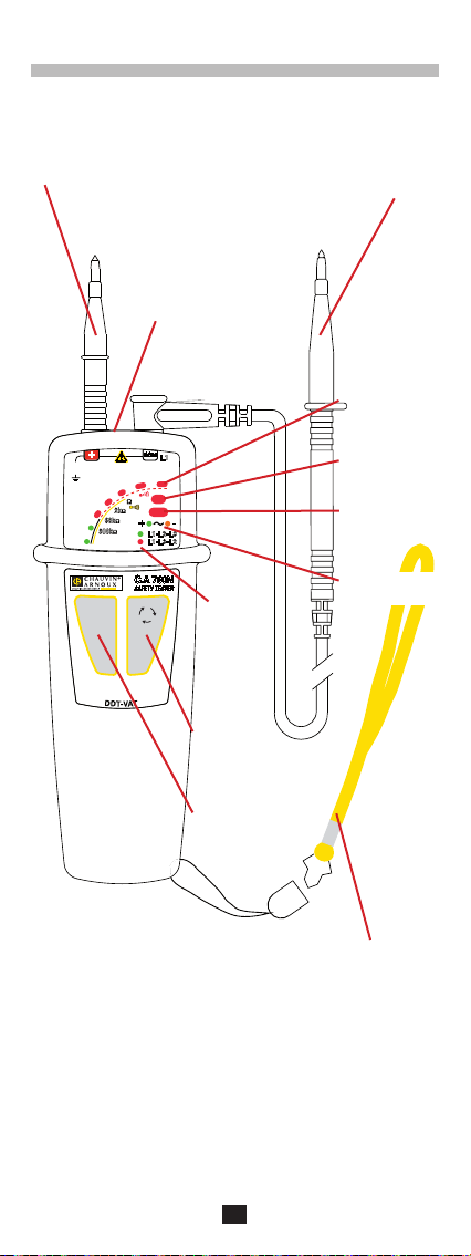
1.1. C.A 760N
Pointe de touche rouge.
Bornes de
raccordement.
COM
+
600V
CAT IV
AC
V
DC
127
50
24
12
AUTO
TEST
300k
230
2k
60k
Ω
Ω
400
Ω
Ω
+
L1-L2-L3
L1-L3-L2
C.A 760N
SAFETY TESTER
L1
L3
L1
690 AC
750 DC
Ph
ELV
L2
-
Ordre des
phases.
Bouton
ordre de
phases.
Cordon noir terminé par
une pointe de touche.
Bargraphe.
Indicateur de
phase.
Indicateur de
tension dangereuse.
Indicateur de
polarité.
Bouton
d’auto test.
4
Dragonne détachable.
Page 5

1.2. AU DOS
Lorsque l’appareil n’est pas utilisé, les pointes de touches
peuvent se ranger au dos.
Protection amovible.
Pointe de touche
rouge.
Gardes.
Pointe de touche
noire.
Trappe à pile.
1.3. C.A 760N IP2X
Voir le § 2.7.
5
Page 6

1.4. FONCTIONNALITÉS
Le C.A 760N est un Détecteur De Tension (DDT) à voyants.
Il est conforme aux prescriptions de la norme IEC 61243-3.
La fonction principale du C.A 760N est la Vérification d’Absence de Tension (VAT). Il détecte les tensions dangereuses,
c’est à dire supérieure à la TBT (très basse tension : 50 Vac
ou 120 Vdc), même si les piles de l’appareil sont usées ou
absentes.
Ses autres fonctions sont :
Indication d’une tension comprise entre 12 et 690 Vac ou
750 Vdc avec indication de la polarité.
Indication de la qualité du niveau de continuité.
Indication de la position de la phase.
Indication de l’ordre des phases.
Les tensions indiquées sur le C.A 760N sont des tensions
nominales. Assurez-vous qu’il sera utilisé sur des réseaux
de tensions normalisées.
6
Page 7

2. UTILISATION
Cet appareil est un détecteur. Les indications qu’il fournit ne
doivent pas être utilisées à des fins de mesure.
2.1. AUTO TEST
Avant d’utiliser le C.A 760N, procédez à un auto test. Il permet
de vérifier l’intégrité des cordons, le bon fonctionnement du
circuit électronique et un niveau de tension suffisant pour
les piles.
Connectez la pointe de touche rouge sur la borne + et le
cordon noir sur la borne COM.
Amenez les 2 pointes de touche en contact et appuyez sur le
bouton AUTO TEST. Maintenez l’appui autant que nécessaire.
Si tous les voyants de l’appareil sauf ELV s’allument et
que le signal sonore retentit, alors l’appareil fonctionne
correctement et peut être utilisé.
300k
60k
230
COM
690 AC
750 DC
400
Ph
Ω
2k
Ω
ELV
Ω
+
Ω
-
CAT IV
V
600V
+
AC
DC
127
50
24
12
Si un voyant sur deux s’allume, c’est qu’il faut remplacer
les piles (voir § 4.2).
60k
300k
2k
60k
230
Ω
Ω
COM
690 AC
750 DC
400
Ph
Ω
2k
Ω
ELV
Ω
Ω
+
Ω
-
CAT IV
V
600V
+
AC
DC
127
50
24
300k
12
7
Page 8

Si un voyant sur trois s’éteint, c’est qu’il y a un problème
au niveau des cordons. Vérifiez qu’ils sont correctement
branchés et qu’ils sont bien en contact et appuyez à nou-
veau sur le bouton AUTO TEST. Si le problème persiste,
le cordon et/ou la pointe de touche doivent être remplacés.
300k
60k
230
COM
690 AC
750 DC
400
Ph
Ω
2k
Ω
ELV
Ω
+
Ω
-
V
600V
CAT IV
AC
DC
12
+
127
50
24
Si aucun voyant n’est allumé, remplacez les piles (voir § 4.2).
Si le problème persiste avec des piles neuves, l’appareil est
défectueux et doit être envoyé en réparation (voir § 4.4).
Après chaque contrôle, refaites un auto test afin de valider
le bon fonctionnement de l’appareil.
Dans une atmosphère bruyante, assurez-vous de bien
entendre le signal sonore émis par l’appareil.
Remarque : Si le on bouton AUTO TEST est maintenu ap-
puyé plus de 10 secondes alors que les pointes
de touche ne sont pas en contact, l’appareil se
met en veille.
2.2. DÉTECTION DE TENSION
Connectez la pointe de touche rouge sur la borne + et le
cordon noir sur la borne COM.
Placez vos mains derrière la garde de l’appareil et de la
pointe de touche.
Position limite des mains.
Placez les pointes de touche sur l’élément à tester et maintenez fermement le contact.
Il n’est pas nécessaire d’allumer le C.A 760N car il se met
en route automatiquement.
8
Page 9

Si la tension présente est :
alternative : les voyants s’allument pour indiquer sa valeur
et les voyants + (vert) et - (orange) sont allumés.
300k
60k
230
COM
690 AC
750 DC
400
Ph
Ω
2k
Ω
ELV
Ω
+
Ω
-
CAT IV
V
600V
+
AC
DC
127
50
24
12
continue : les voyants s’allument pour indiquer sa valeur
et le voyant + (vert) ou le voyant - (orange) s‘allume pour
indiquer la polarité.
300k
60k
230
COM
690 AC
750 DC
400
Ph
Ω
2k
Ω
ELV
Ω
+
Ω
-
CAT IV
V
600V
+
AC
DC
127
50
24
12
dangereuse (> 50 Vac ou 120 Vdc) : le voyant ELV (rouge)
clignote d’autant plus rapidement que la tension présente
est élevée et l’appareil émet des bips sonores.
ELV : Extra Low Voltage ou Très Basse Tension de Sécurité
(TBT). Ce voyant redondant indique que la tension est supérieure à la TBT.
Les deux premiers voyants du bargraphe sont verts pour
indiquer que la tension n’est pas dangereuse et l’appareil
n’émet pas de bip. Les suivants sont rouges et l’appareil
émet des bips.
Si le voyant ELV s’allume seul, les piles sont usées ou
absentes.
300k
60k
230
Ω
COM
690 AC
750 DC
400
Ph
Ω
2k
Ω
ELV
Ω
+
Ω
-
V
600V
CAT IV
AC
DC
12
+
127
50
24
300k
Dans le cas d’une tension à proximité de l’élément testé,
l’appareil peut indiquer la présence d’une tension de service
sur l’élément testé.
9
Page 10

2.3. INDICATION DU NIVEAU DE CONTINUITÉ
Connectez la pointe de touche rouge sur la borne + et le
cordon noir sur la borne COM.
Placez vos mains derrière la garde de l’appareil et de la
pointe de touche.
Placez les pointes de touche sur l’élément à tester et maintenez fermement le contact.
R
Si l’appareil n’a pas été utilisé depuis plus de 30 minutes ou
s’il a été placé en veille, effectuez d’abord un auto test afin
de le placer en veille active.
Si aucune tension n’est détectée, le C.A 760N effectue un
contrôle de continuité.
Si le résultat est :
< 100 W : les 5 premiers voyants du bargraphe clignotent
successivement. L’appareil émet un signal sonore continu.
Comprise entre 100 W et 2 kW : ce sont les 4 premiers
voyants du bargraphe qui s’allument.
Comprise entre 2 kW et 60 kW : ce sont les 3 premiers
voyants du bargraphe qui s’allument.
Comprise entre 60 kW et 300 kW : ce sont les 2 premiers
voyants du bargraphe qui s’allument.
> 300 kW : l’appareil n’affiche rien et n’émet aucun son.
2.4. DÉTECTION DE PHASE
Le C.A 760N effectue une détection de phase unipolaire.
C’est à dire qu’il suffit de brancher une seule pointe de touche
pour savoir si une phase est présente.
Pour fonctionner correctement, la détection de phase doit
être utilisée sur des réseaux référencés à la terre.
Elle permet, par exemple, de savoir où se trouve la phase
sur une prise pour un réseau référencé à la terre.
Connectez la pointe de touche rouge sur la borne +.
Placez vos mains derrière la garde de l’appareil.
Placez la pointe de touche sur l’élément à tester et maintenez
fermement le contact.
10
Page 11

Si la pointe de touche est bien sur la phase, le voyant Ph
(phase) clignote l’appareil émet des bips sonores.
300k
60k
230
COM
690 AC
750 DC
400
Ph
Ω
2k
Ω
ELV
Ω
+
Ω
-
CAT IV
V
600V
+
AC
DC
127
50
24
12
Attention : ce n’est pas parce que le voyant Ph ne clignote
pas qu’il n’y a pas de tension dangereuse sur
la prise.
2.5. ORDRE DES PHASES
Placez la pointe de touche noire sur la première phase du
système triphasé et la pointe de touche rouge sur la deuxième
phase. L’appareil indique la tension présente.
Appuyez sur le bouton .
L1
L2
L3
N
PE
Si la tension est inférieure à 50 Vac ou continue, la fonction
est inhibée.
Sinon, les deux voyants L1-L2-L3 et L1-L3-L2 clignotent
alternativement.
300k
60k
230
COM
L1
690 AC
750 DC
400
Ph
Ω
2k
Ω
ELV
Ω
+
L1-L2-L3
L1-L3-L2
-
Ω
V
600V
CAT IV
AC
DC
12
+
127
50
24
Lorsque le C.A 760N émet deux bips aigus, déplacez la
pointe de touche rouge sur la dernière phase du système.
L’appareil indique la tension présente.
11
Page 12

L1
L2
L3
N
PE
S’il y a un problème, c’est à dire si l’appareil ne détecte
pas de changement de phase dans les 10 secondes ou si
les phases ne sont pas équilibrées, il signale une erreur en
émettant deux bips graves.
Sinon, l’appareil indique l’ordre des phases en allumant :
le voyant L1-L2-L3 et en émettant un bip grave suivi
d’un bip aigu,
ou le voyant L1-L3-L2 et en émettant un bip aigu suivi
d’un bip grave.
2.6. UTILISATION DU C.A 751 (OPTION)
Si vous avez acheté un adaptateur 2P+T, C.A 751, vous
pouvez effectuer une VAT entre la phase et le neutre sur
une prise.
Attention : L’association du C.A 760N et du C.A 751 ramène
Branchez le C.A 751 sur les bornes du C.A 760N puis reportez-vous à la notice de fonctionnement du CA. 751.
l’ensemble du produit à la catégorie de mesure
II 250 V.
Avertissement : L’appareil indiquera une résistance com-
prise entre 60 et 300 kW lorsqu’il sera
connecté.
2.7. POINTES DE TOUCHE IP2X
Les cordons à pointe de touche IP2X sont livrés avec
l’appareil (C.A 760N IP2X) ou en option (C.A 760N) selon le
modèle commandé.
L’utilisation d’accessoires IP2X est un élément complémentaire de sécurité. Ces accessoires peuvent être obligatoires
dans certains pays.
En France, les normes (NF C 18-510, UTE C 18-510) et les
décrets gouvernementaux en imposent l’usage.
12
Page 13

Clipsez la pointe de touche rouge au dos de l’appareil et
tenez la pointe de touche noire à la main.
Pointe de
touche noire.
Gâchettes.
Zones d’appui
pour déverrouillage de la
protection.
Pointe de
touche rouge.
13
Page 14

Pour effectuer un test, appuyez sur la
gâchette. Cela déverrouille la protection
de la pointe qui peut coulisser. Vous pouvez ensuite l’introduire dans une prise ou
l’amener au contact de l’objet à tester.
Pour utiliser l’appareil, tenez-le dans la main, tout en
appuyant avec l’index sur la gâchette de la pointe de touche
rouge.
Tenez la pointe de touche noire dans l’autre main tout en
appuyant avec le pouce sur la gâchette.
14
Page 15

3. CARACTÉRISTIQUES
3.1. CONDITIONS DE RÉFÉRENCE
Grandeur d’influence Valeurs de référence
Température 23 ± 5 °C
Humidité relative 30 à 75 % HR
Tension d’alimentation 3 ± 0,1 V
Fréquence du signal mesuré DC ou 45 à 65 Hz
Type de signal sinusoïdal
Champ électrique extérieur < 1 V/m
Champ magnétique DC extérieur < 40 A/m
3.2. CARACTÉRISTIQUES ÉLECTRIQUES
3.2.1. TENSION
Tensions nominales : 12, 24, 50, 127, 230, 400, 690 Vac/
Vdc et 750 Vdc.
Fréquence de fonctionnement : DC et 16,67 à 800 Hz.
Intensité d’entrée maximale : 3,5 mArms.
Impédance d’entrée > 400 kW.
Temps de réponse < 500 ms.
Le voyant correspondant à la tension V s’allume avant que
la tension atteigne 85%V.
Si aucun voyant n’est allumé, la tension présente est < 12 V.
Le C.A 760N doit être utilisé uniquement sur des réseaux de
tensions normalisées.
Cycle de fonctionnement : 30 s (durée maximale pendant
laquelle l’appareil peut être connecté à un élément sous
tension) - 240 s (temps de repos minimal pendant lequel
le détecteur ne doit pas être connecté à un élément sous
tension).
3.2.2. CONTINUITÉ ET RÉSISTANCE
La détection de continuité est inhibée si une tension > 1 V
est présente.
Les seuils de déclenchement sont :
Courant de test ≤ 1 mA
Tension en circuit ouvert ≤ 3,3 V
100 W < R < 150 W
2 kW < R < 3 kW
60 kW < R < 90 kW
300 kW < R < 450 kW
15
Page 16

3.2.3. REPÉRAGE DE PHASE
15 Hz < fréquence < 65 Hz
50 Vac < tension < 690 Vac pour 45 Hz < fréquence ≤ 65 Hz
150 Vac < tension < 690 Vac pour fréquence < 45 Hz
3.2.4. ORDRE DES PHASES
Fréquence comprise entre 45 et 400 Hz.
Tension comprise entre 50 et 690 Vac entre phases.
Temps d’acquisition des informations après contact ≤ 1 s.
Temps de rétention de l’information : 10 s.
Taux de déséquilibre admissible en amplitude : 20%.
Taux d’harmoniques admissible en tension : 10%.
Réjection des trames de télécommande EDF (TCC-175 Hz188 Hz).
3.3. CONDITIONS D’ENVIRONNEMENT
L’appareil est de type N. Il doit être utilisé dans les conditions
suivantes :
%HR
100
90
80
70
60
50
40
30
20
10
0
3
-50 -40 -30 -20 -10 0 10 20 30 40 50 60 70 80 90
1 : Domaine de référence
2 : Domaine de fonctionnement
-15 à +45 °C et 20 à 95 % HR hors condensation.
(35°C max à 95%HR)
3 : Domaine de stockage (sans pile)
-40 à +70 °C et 20 à 95 % HR hors condensation.
En cas de non utilisation prolongée ou de stockage, retirer
les piles du boîtier.
Utilisation en intérieur et en extérieur sans pluie.
Degré de pollution : 2.
Altitude : < 2000 m.
1
2
°C
3.4. ALIMENTATION
L’alimentation du C.A 760N est réalisée par deux piles 1,5 V
alcaline (type AAA ou LR3).
L’autonomie est de 7 000 mesures de 10 secondes.
16
Page 17

Les piles peuvent être remplacées par des accumulateurs
rechargeables, mais l’autonomie sera bien moindre.
3.5. CARACTÉRISTIQUES CONSTRUCTIVES
Dimensions (L x l x P) 163 x 64 x 40 mm
Masse environ 210 g
Cordon longueur 90 cm
Indice de protection IP 65 selon IEC 60529
IK 04 selon IEC 50102
Chute 2 mètres.
3.6. CONFORMITÉ AUX NORMES INTERNATIONALES
Détecteur de tension bipolaire IEC 61243-3 Ed. 2 de 2009.
3.7. COMPATIBILITÉ ÉLECTROMAGNÉTIQUE
Émission et immunité en milieu industriel selon IEC 61326-1.
17
Page 18

4. MAINTENANCE
Excepté les piles, l’appareil ne comporte aucune
pièce susceptible d’être remplacée par un personnel non
formé et non agréé. Toute intervention non agréée ou
tout remplacement de pièce par des équivalences risque
de compromettre gravement la sécurité.
4.1. NETTOYAGE
Déconnectez tout branchement de l’appareil.
Utilisez un chiffon doux, légèrement imbibé d’eau savonneuse. Rincez avec un chiffon humide et séchez rapidement
avec un chiffon sec ou de l’air pulsé. N’utilisez pas d’alcool,
de solvant ou d’hydrocarbure.
4.2. REMPLACEMENT DES PILES
Si, lors de l’auto test, seule la moitié des voyants s’allume,
vous devez remplacer les piles.
Déconnectez tout branchement de l’appareil.
A l’aide d’un tournevis, dévissez les deux vis imperdables
de la trappe à pile située sous l’appareil.
Retirez les piles usagées et remplacez-les par deux piles
neuve (piles 1,5 V alcaline de type AAA ou LR3).
Refermez la trappe à pile et assurez-vous de sa fermeture
complète et correcte.
Revissez les deux vis.
Les piles et les accumulateurs usagés ne doivent
pas être traités comme des déchets ménagers.
Rapportez-les au point de collecte approprié pour
le recyclage.
4.3. VÉRIFICATION MÉTROLOGIQUE
Comme tous les appareils de mesure ou d’essais,
une vérification périodique est nécessaire.
Nous vous conseillons une vérification annuelle de cet appareil. Pour les vérifications et étalonnages, adressez-vous à
nos laboratoires de métrologie accrédités COFRAC ou aux
centres techniques MANUMESURE.
Renseignements et coordonnées sur demande :
Tél. : 02 31 64 51 43 - Fax : 02 31 64 51 09
4.4. RÉPARATION
Pour les réparations sous garantie et hors garantie, contactez
votre agence commerciale Chauvin Arnoux la plus proche
ou votre centre technique régional Manumesure qui établira
18
Page 19

un dossier de retour et vous communiquera la procédure
à suivre.
Coordonnées disponibles sur notre site : http://www.chauvin-arnoux.com ou par téléphone aux numéros suivants :
02 31 64 51 55 (centre technique Manumesure),
01 44 85 44 85 (Chauvin Arnoux).
Pour les réparations hors de France métropolitaine, sous
garantie et hors garantie, retournez l’appareil à votre agence
Chauvin Arnoux locale ou à votre distributeur.
19
Page 20

5. GARANTIE
Notre garantie s’exerce, sauf stipulation expresse, pendant
douze mois après la date de mise à disposition du matériel.
L’extrait de nos Conditions Générales de Vente sera communiqué sur demande.
La garantie ne s’applique pas suite à :
une utilisation inappropriée de l'équipement ou à une
utilisation avec un matériel incompatible ;
des modifications apportées à l'équipement sans l'autori-
sation explicite du service technique du fabricant ;
des travaux effectués sur l'appareil par une personne non
agréée par le fabricant ;
une adaptation à une application particulière, non prévue
par la définition du matériel ou non indiquée dans la notice
de fonctionnement ;
des dommages dus à des chocs, chutes ou inondations.
20
Page 21

6. POUR COMMANDER
Détecteur de tension C.A 760N ....................P01191761Z
Livré sous blister avec :
une pointe de touche rouge Ø 2 mm,
un cordon noir terminé par une pointe de touche Ø 2 mm,
une dragonne,
deux piles alcaline AAA ou LR3,
une notice de fonctionnement 5 langues,
un certificat de vérification.
Détecteur de tension C.A 760N IP2X ...........P01191761B
Livré sous blister avec :
un cordon noir de 85 cm et un cordon rouge de 25 cm
terminés par une pointe de IP2X Ø 4 mm,
une dragonne,
deux piles alcaline AAA ou LR3,
une notice de fonctionnement 5 langues,
un certificat de vérification.
6.1. ACCESSOIRES ET RECHANGES
Pointe de touche rouge Ø 2 mm ...................... P01102008Z
Cordon noir avec pointe de touche Ø 2 mm .... P01102009Z
Cordons noir et rouge de 1,5 m à pointe IP2X
Ø 4 mm ............................................................. P01295462Z
Cordons noir et rouge de 1,5 m à pointe IP2X
Ø 2 mm ............................................................. P01295463Z
Cordon noir 85 cm et cordon rouge 25 cm
à pointe de IP2X Ø 4 mm ................................. P01295285Z
Sacoche de transport ....................................... P01298012
Adaptateur 2P+T, C.A 751 ............................... P01101997Z
21
Page 22

ENGLISH
Thank you for purchasing a C.A 760N or C.A 760N IP2X
voltage detector.
For best results from your instrument:
read these operating instructions carefully,
comply with the precautions for use.
WARNING, risk of DANGER! The operator must
refer to these instructions whenever this danger
symbol appears.
Equipment protected by double insulation.
Equipment suitable for live work.
Battery.
Earth.
The CE marking indicates conformity with
European directives, in particular LVD and EMC.
The rubbish bin with a line through it indicates that,
in the European Union, the product must undergo
selective disposal in compliance with Directive
WEEE 2002/96/EC. This equipment must not be
treated as household waste.
Definition of measurement categories:
Measurement category IV corresponds to measurements
taken at the source of low-voltage installations.
Example: power feeders, counters and protection devices.
Measurement category III corresponds to measurements
on building installations.
Example: distribution panel, circuit-breakers, machines
or fixed industrial devices.
Measurement category II corresponds to measurements
taken on circuits directly connected to low-voltage instal-
lations.
Example: power supply to domestic electrical appliances
and portable tools.
22
Page 23

PRECAUTIONS FOR USE
This device is protected against voltages up to 600V with
respect to earth in measurement category IV.
The protection provided by the device may be compromised
if it is used other than as specified by the manufacturer and
so endanger the user.
Do not exceed the maximum rated voltage and current and
the measurement category. Do not use your instrument
on networks of which the voltage or category exceeds
those stated.
Comply with the conditions of use, namely the temperature,
the humidity, the altitude, the degree of pollution, and the
place of use.
When handling the test probes, keep your fingers behind
the physical guard.
Use connection accessories of which the measurement
category and service voltage are at least equal to those
of the device.
Do not use the device if it is open, damaged, or poorly reas-
sembled, or its accessories if they seem to be damaged.
The device is designed to be used by qualified personnel
and in compliance with national safety rules.
We recommend wearing personal protective equipment
when the environment in which the device is used makes
it necessary.
All troubleshooting and metrological checks must be done
by competent, accredited personnel.
CONTENTS
1. Presentation ...............................................................24
2. Use ..............................................................................27
3. Characteristics ..........................................................35
4. Maintenance ..............................................................37
5. Warranty ....................................................................38
6. To order ......................................................................39
23
Page 24

1. PRESENTATION
1.1. C.A 760N
Red test probe.
+
600V
CAT IV
230
AC
V
DC
127
2k
50
60k
Ω
24
300k
Ω
12
AUTO
TEST
Connection
terminals.
COM
L1
690 AC
750 DC
400
Ph
Ω
Ω
ELV
+
-
L1-L2-L3
L1-L3-L2
C.A 760N
SAFETY TESTER
L1
L3
L2
Phase
order.
Phase
order
button.
Black lead terminated
by a test probe.
Bargraph.
Phase indicator.
Hazardous
voltage indicator.
Polarity indicator.
Self-test
button.
24
Detachable strap.
Page 25

1.2. ON THE BACK
When the device is not in use, the test probes can be stowed
on the back.
Removable protective caps.
Red test probe.
Guards.
Black test probe.
Battery compartment cover.
1.3. C.A 760N IP2X
See §2.7.
25
Page 26

1.4. FUNCTIONS
The C.A 760N is a Voltage Detector with indicator lights.
It complies with the requirements of standard IEC 61243-3.
The main function of the C.A 760N is to test for the absence of
any voltage. It detects hazardous voltages, meaning voltages
exceeding the ELV (extra low voltage: 50 Vac or 120 Vdc),
even if its batteries are low or missing.
Its other functions are:
Indication of a voltage between 12 and 690 Vac or 750 Vdc,
with indication of the polarity.
Continuity level quality indication.
Phase position indication.
Phase order indication.
The voltages indicated on the C.A 760N are nominal voltages. Make sure that the device will be used on networks at
standardized voltages.
26
Page 27

2. USE
This device is a detector. The indications it provides must
not be used for measurement purposes.
2.1. SELF-TEST
Before using the C.A 760N, perform a self-test. This checks
the integrity of the leads, the proper operation of the electronic circuit, and the battery voltage.
Connect the red test probe to the + terminal and the black
lead to the COM terminal.
Touch the 2 test probes together and press the AUTO TEST
button. Press for as long as necessary.
If all of the indicators of the device except ELV light and
the audible signal sound, the device is working properly
and can be used.
300k
60k
230
COM
690 AC
750 DC
400
Ph
Ω
2k
Ω
ELV
Ω
+
Ω
-
CAT IV
V
600V
+
AC
DC
127
50
24
12
If every other indicator lights, the batteries must be replaced
(see §4.2).
60k
300k
2k
60k
230
Ω
Ω
COM
690 AC
750 DC
400
Ph
Ω
2k
Ω
ELV
Ω
Ω
+
Ω
-
CAT IV
V
600V
+
AC
DC
127
50
24
300k
12
27
Page 28

If every third indicator is off, there is a problem with the
leads. Check that they are correctly connected and that
they are actually touching, then press the AUTO TEST
button again. If the problem persists, the lead and/or the
test probe must be replaced.
300k
60k
230
COM
690 AC
750 DC
400
Ph
Ω
2k
Ω
ELV
Ω
+
Ω
-
V
600V
CAT IV
AC
DC
12
+
127
50
24
If no indicator lights, replace the batteries (see §4.2). If the
problem persists with new batteries, the device is defective
and must be sent in for repair (see §4.4).
After each check, perform a self-test in order to confirm the
proper operation of the device.
In a noisy environment, make sure that you can in fact hear
the audible signal emitted by the device.
Remark: If the AUTO TEST button is kept pressed for
more than 10 seconds when the test probes are
not touching each other, the device switches to
standby.
2.2. VOLTAGE DETECTION
Connect the red test probe to the + terminal and the black
lead to the COM terminal.
Keep your hands behind the guards of the device and of
the test probe.
Position beyond which your hands must not go.
Place the test probes on the element to be tested and maintain a firm contact.
There is no need to switch the C.A 760N on, because it starts
up automatically.
28
Page 29

If the voltage present is:
AC, the indicators light to indicate its value and the + (green)
and - (orange) indicators light.
300k
60k
230
COM
690 AC
750 DC
400
Ph
Ω
2k
Ω
ELV
Ω
+
Ω
-
CAT IV
V
600V
+
AC
DC
127
50
24
12
DC, the indicators light to indicate its value and the + in-
dicator (green) or the - indicator (orange) lights to indicate
the polarity.
300k
60k
230
COM
690 AC
750 DC
400
Ph
Ω
2k
Ω
ELV
Ω
+
Ω
-
CAT IV
V
600V
+
AC
DC
127
50
24
12
hazardous (>50 Vac or 120 Vdc): the higher the voltage,
the faster the ELV indicator (red) flashes; the device also
emits audible beeps.
ELV : Extra Low Voltage. This redundant indicator indicates
that the voltage is greater than the ELV.
The first two indicators of the bargraph are green to
indicate that the voltage is not hazardous and the device
does not beep. The remaining indicators are red and the
device beeps.
If only the ELV indicator lights, the batteries are low or
missing.
300k
60k
230
Ω
COM
690 AC
750 DC
400
Ph
Ω
2k
Ω
ELV
Ω
+
Ω
-
V
600V
CAT IV
AC
DC
12
+
127
50
24
300k
If there is a voltage near the element being tested, the device
may indicate the presence of an operating voltage on the
element being tested.
29
Page 30

2.3. CONTINUITY LEVEL INDICATION
Connect the red test probe to the + terminal and the black
lead to the COM terminal.
Keep your hands behind the guards of the device and of
the test probe.
Place the test probes on the element to be tested and maintain a firm contact.
R
If the device has been left unused for more than 30 minutes
or has been set to standby, first perform a SELF-TEST in
order to switch it to hot standby.
If no voltage is detected, the C.A 760N performs a continuity test.
If the result is:
<100W: the first 5 indicators of the bargraph blink one after
another. The device emits a continuous audible signal.
Between 100W and 2kW: the first 4 indicators of the
bargraph light.
Between 2kW and60kW: the first 3 indicators of the
bargraph light.
Between 60kW and 300kW: the first 2 indicators of the
bargraph light.
>300kW: the device displays nothing and does not emit
a sound.
2.4. PHASE DETECTION
The C.A 760N performs a unipolar phase detection. This
means that connecting a single test probe is enough to
determine whether a phase is present.
To operate correctly, the phase detection function must be
used on networks referred to earth.
It can be used, for example, to locate the phase on an outlet
of a network referred to earth.
Connect the red test probe to the + terminal
Keep your hands behind the guards of the device
Place the test probes on the element to be tested and maintain a firm contact.
30
Page 31

If the test probe is in fact on the phase, the Ph (phase) indicator flashes and the device beeps.
300k
60k
230
COM
690 AC
750 DC
400
Ph
Ω
2k
Ω
ELV
Ω
+
Ω
-
CAT IV
V
600V
+
AC
DC
127
50
24
12
Warning: if the Ph indicator is not flashing, that does not
mean that there is no hazardous voltage on the
outlet.
2.5. PHASE ORDER
Place the black test probe on the first phase of the threephase system and the red test probe on the second phase.
The device indicates the voltage present.
Press the button.
L1
L2
L3
N
PE
If the voltage is less than 50 Vac or dc, the function is
disabled.
Otherwise, the two indicators, L1-L2-L3 and L1-L3-L2,
blink alternately.
300k
60k
230
COM
L1
690 AC
750 DC
400
Ph
Ω
2k
Ω
ELV
Ω
+
L1-L2-L3
L1-L3-L2
-
Ω
600V
CAT IV
V
+
AC
DC
127
50
24
12
When the C.A 760N emits two high-pitched beeps, shift the
red test probe to the last phase of the system. The device
indicates the voltage present.
31
Page 32

L1
L2
L3
N
PE
If there is a problem, in other words, if the device fails to
detect a change of phase within 10 seconds or if the phases
are not balanced, it reports an error by emitting two lowpitched beeps.
Otherwise, the device indicates the phase order by lighting:
the L1-L2-L3 indicator and emitting a low-pitched beep,
followed by a high-pitched beep,
or the L1-L3-L2 indicator and emitting a high-pitched beep
followed by a low-pitched beep.
2.6. USING THE C.A 751 (OPTION)
If you have purchased a C.A 751 2P+T adapter, you can test
for the absence of voltage between the phase and neutral
on an outlet.
Attention: Pairing the C.A 760N with the C.A 751 derates
Connect the C.A 751 to the terminals of the C.A 760N, then
refer to the operating instructions of the CA.751.
the combined product to measurement category
II, 250V.
Warning: The device will indicate a resistance between 60
and 300kW when it is connected.
2.7. IP2X PROBE TIPS
Leads with IP2X probe tips are supplied with the device either
as standard (C.A 740N IP2X) or as an option (C.A 740N),
depending on the model ordered.
IP2X accessories contribute to safety. These accessories are
mandatory in some countries.
32
Page 33

Clip the red probe tip to the back of the device and hold the
black probe tip in your hand.
Black probe
tip.
Triggers.
Where to
press to unlock the protection.
Red probe tip.
33
Page 34

To perform a test, press the trigger. That
unlocks the protection of the probe tip,
which can slide. You can then insert it
in an outlet or touch the object to be
tested with it.
To use the device, hold it in your hand while pressing the
trigger of the red probe tip with your index finger.
Hold the black probe tip in your other hand while pressing
the trigger with your thumb.
AUTO TEST
34
Page 35

3. CHARACTERISTICS
3.1. REFERENCE CONDITIONS
Quantity of influence Reference values
Temperature 23±5°C
Relative humidity 30 to 75 % HR
Supply voltage 3±0,1V
Frequency of the measured signal DC or 45 to 65 Hz
Type of signal sinusoidal
External electric field <1V/m
DC external magnetic field <40A/m
3.2. ELECTRICAL CHARACTERISTICS
3.2.1. VOLTAGE
Nominal voltages: 12, 24, 50, 127, 230, 400, 690 Vac/Vdc
and 750 Vdc.
Frequency of operation: DC and 16.67 at 800Hz.
Maximum input current: 3.5 mArms.
Input impedance >300kW.
Response time <500ms.
The indicator corresponding to voltage V lights before the
voltage reaches 85% V.
If no indicator lights, the voltage present is < 12V.
The C.A 760N must be used only on networks at standardized voltages.
Operating cycle: 30s (maximum duration for which the device
can remain connected to a live element) - 240s (minimum
resting time during which the detector must not be connected
to a live element).
3.2.2. CONTINUITY AND RESISTANCE
Continuity detection is disabled if a voltage > 1V is present.
The triggering thresholds are:
Test current ≤1mA
Open-circuit voltage ≤3.3V
100W<R<150W
2kW<R<3kW
60kW<R<90kW
300 W<R<450kW
35
Page 36

3.2.3. PHASE IDENTIFICATION
15Hz<frequency<65Hz
50 Vac<voltage<690 Vac and 45Hz<frequency ≤65Hz
150 Vac<voltage<690 Vac and frequency<45Hz
3.2.4. PHASE-ORDER
Frequency between 45 and 400Hz.
Voltage between 50 and 690 Vac between phases.
Time to acquisition of the information after contact ≤1s.
Retention time of the information: 10s.
Acceptable amplitude unbalance: 20%.
Acceptable level of harmonics in voltage: 10%.
Rejection of power company remote control signals (TCC175Hz-188Hz).
3.3. ENVIRONMENTAL CONDITIONS
The device is of type N. It must be used under the following
conditions:
%RH
100
90
80
70
60
50
40
30
20
10
0
3
-50 -40 -30 -20 -10 0 10 20 30 40 50 60 70 80 90
1: Reference domain
2: Operating range
-15 to +45°C and 20 to 95% RH without condensation.
(35°C max. at 95% RH)
3: Range in storage (without batteries)
-40 to +70°C and 20 to 95% RH without condensation.
If an extended period of non-use is anticipated, or for storage,
withdraw the batteries from the housing.
For use indoors and outdoors without rain.
Pollution degree: 2.
Altitude: <2000m.
1
2
°C
3.4. ALIMENTATION
The C.A 760N is powered by two 1.5V alkaline batteries
(type AAA or LR3).
The battery life is 7,000 10-second measurements.
36
Page 37

The batteries can be replaced by rechargeable batteries, but
the life between charges will be much shorter.
3.5. CHARACTERISTICS OF CONSTRUCTION
Dimensions (LxWxH) 163 x 64 x 40mm
Weight approximately 210g
Cord length 90cm
Protection class IP65 per IEC 60529
IK04 per IEC 50102
Drop 2 metres
3.6. COMPLIANCE WITH INTERNATIONAL
STANDARDS
Two-pole voltage detector per IEC 61243-3 ed. 2 of 2009.
3.7. ELECTROMAGNETIC COMPATIBILITY
Emissions and immunity in an industrial setting compliant
with IEC 61326-1.
4. MAINTENANCE
Except for the batteries, the instrument contains
no parts that can be replaced by personnel who have not
been specially trained and accredited. Any unauthorized
repair or replacement of a part by an “equivalent” may
gravely impair safety.
4.1. CLEANING
Disconnect the instrument completely.
Use a soft cloth, dampened with soapy water. Rinse with a
damp cloth and dry rapidly with a dry cloth or forced air. Do
not use alcohol, solvents, or hydrocarbons.
4.2. REPLACEMENT OF BATTERIES
If, during the self-test, only half of the indicators light, you
must replace the batteries.
Disconnect anything connected to the device.
Using a screwdriver, unscrew the two captive screws of
the battery compartment cover located on the back of
the device.
Withdraw the spent batteries and replace them with two
37
Page 38

new batteries (AAA or LR3 1.5V alkaline batteries).
Close the battery compartment cover and make sure that
it is completely and correctly closed.
Screw the two screws back in.
Spent batteries must not be treated as ordinary
household waste. Take them to the appropriate
recycling collection point.
4.3. METROLOGICAL CHECK
Like all measuring or testing devices, the instrument
must be checked regularly.
This instrument should be checked at least once a year.
For checking and calibration, contact one of our accredited
metrology laboratories (information and contact details
available on request), at our Chauvin Arnoux subsidiary or
the branch in your country.
4.4. REPAIR
For all repairs before or after expiry of warranty, please return
the device to your distributor.
5. WARRANTY
Except as otherwise stated, our warranty is valid for twelve
months starting from the date on which the equipment was
sold. Extract from our General Conditions of Sale provided
on request.
The warranty does not apply in the following cases:
Inappropriate use of the equipment or use with incompat-
ible equipment;
Modifications made to the equipment without the explicit
permission of the manufacturer’s technical staff;
Work done on the device by a person not approved by
the manufacturer;
Adaptation to a particular application not anticipated in
the definition of the equipment or not indicated in the
user’s manual;
Damage caused by shocks, falls, or floods.
38
Page 39

6. TO ORDER
C.A 760N voltage detector ............................P01191761Z
Delivered in blister pack with:
one red test probe 2mm in diameter,
one black lead terminated by a test probe 2mm in diameter,
one strap,
two AAA or LR3 alkaline batteries,
one user’s manual in 5 languages,
one verification certificate.
C.A 760N IP2X voltage detector ...................P01191761B
Delivered in blister pack with:
one 85cm black lead and one 25cm red lead terminated
by an IP2X probe tip 4mm in diameter,
one strap,
two AAA or LR3 alkaline batteries,
one user’s manual in 5 languages,
one verification certificate.
6.1. ACCESSORIES AND OPTIONS
One red test probe 2mm in diameter .............. P01102008Z
Black lead with test probe 2mm in diameter .... P01102009Z
Black and red leads 1.5m long with IP2X probe
tips 4mm in diameter ........................................ P01295462Z
Black and red leads 1.5m long with IP2X probe
tips 2mm in diameter ........................................ P01295463Z
Black lead 85cm long and red lead 25cm long
with IP2X probe tip 4mm in diameter ............... P01295285Z
Carrying bag ..................................................... P01298012
C.A 751 2P+T adapter ...................................... P01101997Z
39
Page 40

DEUTSCH
Sie haben einen Spannungsprüfer C.A 760N oder C.A 760N
IP2X erworben und wir danken Ihnen für Ihr Vertrauen.
Um die optimale Benutzung Ihres Gerätes zu gewährleisten,
bitten wir Sie:
diese Bedienungsanleitung sorgfältig zu lesen
die Benutzungshinweise genau zu beachten.
ACHTUNG, GEFAHR! Sobald dieses
Gefahrenzeichen irgendwo erscheint, ist der
Benutzer verpflichtet, die Anleitung zu Rate zu ziehen.
Das Gerät ist durch eine doppelte Isolierung
geschützt.
Tauglich für Arbeiten unter Spannung.
Batterie.
Erde.
Die CE-Kennzeichnung bestätigt die
Übereinstimmung mit den europäischen
Richtlinien, insbesondere der NiederspannungsRichtlinie und der EMV-Richtlinie.
Der durchgestrichene Mülleimer bedeutet, dass
das Produkt in der europäischen Union gemäß
der WEEE-Richtlinie 2002/96/EG einer getrennten Elektroschrott-Verwertung zugeführt werden
muss. Das Produkt darf nicht als Haushaltsmüll
entsorgt werden.
Definition der Messkategorien:
Die Kategorie IV bezieht sich auf Messungen, die an der
Quelle von Niederspannungsinstallationen vorgenommen
werden.
Beispiele: Anschluss an das Stromnetz, Energiezähler und
Schutzeinrichtungen.
Die Kategorie III bezieht sich auf Messungen, die an der
Elektroinstallation eines Gebäudes vorgenommen werden.
Beispiele: Verteilerschränke, Trennschalter, Sicherungen,
stationäre industrielle Maschinen und Geräte.
Die Kategorie II bezieht sich auf Messungen, die direkt an
Kreisen der Niederspannungs-Installation vorgenommen
werden.
Beispiele: Stromanschluss von Haushaltsgeräten oder
tragbaren Elektrowerkzeugen.
40
Page 41

SICHERHEITSHINWEISE
Geräteschutz für max. Spannung von 600V gegenüber Erde
bei Anlagen der Messkategorie IV.
Der Geräteschutz und damit eine gefahrlose Handhabung sind
nur dann gegeben, wenn das Gerät nach Herstellerangaben
verwendet wird.
Halten Sie sich an die Messkategorie und die max. zul.
Nennspannungen und -ströme. Verwenden Sie das
Gerät niemals in höherwertigen Spannungsnetzen und
Überspannungskategorien als angegeben!
Verwenden Sie das Gerät ausschließlich unter den vorgege-
benen Einsatzbedingungen bzgl. Temperatur, Feuchtigkeit,
Höhe, Verschmutzungsgrad und Einsatzort.
Fassen Sie Tastspitzen immer nur hinter dem Fingerschutz
an.
Verwenden Sie Anschlusszubehör, dessen Messkategorie
und Betriebsspannung dem Messgerät entsprechen.
Das Gerät nur mit korrekt geschlossenem, unbeschädigtem
und richtig montiertem Gehäuse verwenden. Benutzen Sie
niemals Zubehörteile, wenn diese beschädigt erscheinen.
Das Gerät ist für Fachleute bestimmt, die es gemäß den
staatlichen Sicherheitsvorgaben verwenden.
Die Verwendung einer persönlichen Schutzausrüstung
wird empfohlen, wenn die Einsatzbedingungen des Geräts
dieses erfordern.
Fehlerbehebung und Eichung darf nur durch zugelassenes
Fachpersonal erfolgen.
INHALTSVERZEICHNIS
1. Vorstellung .................................................................42
2. Verwendung ...............................................................45
3. Technische Daten ......................................................53
4. Wartung ......................................................................55
5. Garantie ......................................................................56
6. Bestellangaben .........................................................57
41
Page 42

1. VORSTELLUNG
1.1. C.A 760N
Rote Tastspitze
+
600V
CAT IV
230
AC
V
DC
127
2k
50
60k
Ω
24
300k
Ω
12
AUTO
TEST
Anschlussbuchsen
COM
L1
690 AC
750 DC
400
Ph
Ω
Ω
ELV
+
-
L1-L2-L3
L1-L3-L2
C.A 760N
SAFETY TESTER
L1
Phasen-
L3
L2
folge
Taste für
Phasenfolge
Fest angeschlossenes Kabel
(schwarz) an Tastspitze
Balkenanzeige
Phasenanzeige
Anzeige bei
Gefahrenspannung
Polaritätsanzeige
Taste für
Selbsttest
42
Abnehmbare
Trageschlaufe
Page 43

1.2. RÜCKSEITE
Die Tastspitzen finden an der Rückseite Platz, wenn das
Gerät nicht im Einsatz ist.
Stöpsel
Rote Tastspitze
Fingerschutz
Schwarze Tastspitze
Batteriefach.
1.3. C.A 760N IP2X
Siehe Kapitel 2.7.
43
Page 44

1.4. FUNKTIONSUMFANG
C.A 760N ist ein Spannungsprüfer mit LEDs.
Entspricht der IEC 61243-3-Norm.
Die Hauptfunktion des C.A 760N ist die Überprüfung der
Spannungsfreiheit. Das Gerät erkennt auch bei fehlender
oder schwacher Batterie eine Gefahrenspannung, das heißt
alle die Schutzkleinspannung (ELV: 50 Vac bzw. 120 Vdc)
übersteigenden Spannungen.
Sonstige Gerätefunktionen:
Spannungsprüfung von 12 bis 690 Vac bzw. 750 Vdc mit
Polaritätsanzeige
Durchgängigkeitsqualität
Phasenanzeige
Phasenfolge-Anzeige
Der C.A 760N zeigt Nennspannungswerte an. Stellen Sie sicher, dass das Gerät nur an normgerechten Spannungsnetzen
angelegt wird.
44
Page 45

2. VERWENDUNG
Es handelt sich um ein Prüfgerät, das nicht für Messeinsätze
geeignet ist.
2.1. SELBSTTEST
Führen Sie einen Selbsttest durch, bevor Sie den C.A 760N
verwenden. Der Geräte-Selbsttest überprüft, dass die Kabel
unbeschädigt sind, dass der Schaltkreis einwandfrei funktioniert und dass die Batterien nicht zu schwach sind.
Stecken Sie dazu die rote Tastspitze in die +-Buchse und die
schwarze Leitung in den COM-Anschluss.
Halten Sie dann die beiden Tastspitzen aneinander und drücken Sie auf AUTO TEST. Die Taste solange gedrückt halten,
wie es erforderlich ist.
Alle LEDs am Gerät mit Ausnahme von ELV leuchten und
der Buzzer ertönt: Das Gerät funktioniert einwandfrei und
darf verwendet werden.
300k
60k
230
COM
690 AC
750 DC
400
Ph
Ω
2k
Ω
ELV
Ω
+
Ω
-
CAT IV
V
600V
+
AC
DC
127
50
24
12
Jede zweite LED leuchtet: Die Batterien müssen ausge-
tauscht werden (siehe Abs. 4.2.).
60k
300k
2k
60k
230
Ω
Ω
COM
690 AC
750 DC
400
Ph
Ω
2k
Ω
ELV
Ω
Ω
+
Ω
-
CAT IV
V
600V
+
AC
DC
127
50
24
300k
12
45
Page 46

Jede dritte LED leuchtet nicht: Die Leitungen sind gestört.
Sie müssen überprüfen, ob die Leitungen ordentlich ange-
schlossen sind und Kontakt haben. Dann den AUTO TEST
wiederholen. Wenn das Problem damit nicht behoben
ist, müssen Sie die Leitung und/oder die Tastspitze aus-
tauschen.
300k
60k
230
COM
690 AC
750 DC
400
Ph
Ω
2k
Ω
ELV
Ω
+
Ω
-
V
600V
CAT IV
AC
DC
12
+
127
50
24
Keine einzige LED leuchtet: Die Batterien müssen ausge-
tauscht werden (siehe Abs. 4.2.). Wenn das Problem damit
nicht behoben ist, liegt ein Fehler im Gerät vor. Schicken
Sie es zur Reparatur ein (siehe Abs. 4.4).
Nach jedem Einsatz sollten Sie einen Selbsttest durchführen,
um den einwandfreien Betrieb des Geräts sicherzustellen.
Achten Sie besonders bei Lärm darauf, dass Sie den Buzzer
auch wirklich hören.
Hinweis: Drückt man länger als 10 Sek. auf AUTO TEST,
ohne dass die Tastspitzen sich dabei berühren,
schaltet das Gerät auf Standby.
2.2. SPANNUNGSPRÜFUNG
Stecken Sie dazu die rote Tastspitze in die +-Buchse und die
schwarze Leitung in den COM-Anschluss.
Fassen Sie das Gerät immer hinter dem Fingerschutz an
Gerät und Tastspitze an.
Äußerste Position der Hände.
Halten Sie die Tastspitzen fest an den Prüfling.
C.A 760N braucht nicht extra eingeschaltet zu werden, dies
geschieht automatisch.
46
Page 47

Spannung vorhanden mit folgender Anzeige:
Wechselspannung: Die LEDs zeigen den Wert an und die
LEDs + (grün) und- (orange) leuchten.
300k
60k
230
COM
690 AC
750 DC
400
Ph
Ω
2k
Ω
ELV
Ω
+
Ω
-
CAT IV
V
600V
+
AC
DC
127
50
24
12
Gleichspannung: Die LEDs zeigen den Wert an und die
LED + (grün) oder die LED- (orange) leuchtet und zeigt
damit die Polarität an.
300k
230
60k
COM
690 AC
750 DC
400
Ph
Ω
2k
Ω
ELV
Ω
+
Ω
-
CAT IV
V
600V
+
AC
DC
127
50
24
12
Gefahrenspannung, d.h. >50 Vac bzw. 120 Vdc): Die LED
ELV (rot) blickt umso schneller, je größer die Spannung ist.
Außerdem erklingt ein akustisches BEEP-Signal.
ELV : Extra Low Voltage (ELV) bzw. Schutzkleinspannung.
Diese Zusatz-LED zeigt an, dass die Schutzkleinspannung
überschritten ist.
Die ersten beiden LEDs im Balkendiagramm sind grün und
bedeuten, dass keine Gefahrenspannung vorliegt. Kein
akustisches Signal. Alle anderen Balken sind rot und das
Gerät lässt ein akustisches Signal ertönen.
Nur die LED ELV leuchtet auf: die Batterien sind schwach
bzw. fehlen.
300k
60k
230
Ω
COM
690 AC
750 DC
400
Ph
Ω
2k
Ω
ELV
Ω
+
Ω
-
V
600V
CAT IV
AC
DC
12
+
127
50
24
300k
Es kann vorkommen, dass der Spannungsprüfer eine
Betriebsspannung am Prüfling anzeigt, wenn nahe am
Prüfling Spannung vorhanden ist.
47
Page 48

2.3. DURCHGÄNGIGKEITSANZEIGE
Stecken Sie dazu die rote Tastspitze in die +-Buchse und die
schwarze Leitung in den COM-Anschluss.
Fassen Sie das Gerät immer hinter dem Fingerschutz an
Gerät und Tastspitze an.
Halten Sie die Tastspitzen fest an den Prüfling.
R
Wenn Sie das Gerät seit mehr als einer halben Stunde nicht
mehr verwendet haben bzw. wenn es auf Standby war, führen
Sie zuerst einen SELBSTTEST durch. Damit wird das Gerät
wieder „aufgeweckt“.
C.A 760N nimmt die Durchgangsprüfung vor, wenn keine
Spannung vorhanden ist.
Folgendes Ergebnis:
<100W: die ersten fünf LEDs der Balkenanzeige blinken
nacheinander. Ein durchgehender Summton erklingt.
Zwischen 100W und 2kW: die ersten vier LEDs der
Balkenanzeige leuchten.
Zwischen 2kW und 60kW: die ersten drei LEDs der
Balkenanzeige leuchten.
Zwischen 60kW und 300kW: die ersten drei LEDs der
Balkenanzeige leuchten.
>300kW: Keine Anzeige und kein akustisches Signal.
2.4. PHASENPRÜFUNG
Die Phasenprüfung am C.A 760N ist einpolig, das heißt Sie
brauchen nur eine Tastspitze anzuschließen, um die Phase
zu erheben.
Die Phasenprüfung kann nur ordentlich erfolgen, wenn eine
Bezugserde vorhanden ist.
Sie dient zum Beispiel dazu, an einem Stecker festzustellen,
wo die Phase ist.
Schließen Sie die rote Tastspitze an die Buchse + an.
Halten Sie das Gerät mit den Händen hinter dem Fingerschutz.
Halten Sie die Tastspitze fest an den Prüfling.
48
Page 49

Wenn die Tastspitze an der Phase liegt, blinkt die LED Ph
L1
(Phase). Außerdem erklingt ein akustisches BEEP-Signal.
300k
60k
230
COM
690 AC
750 DC
400
Ph
Ω
2k
Ω
ELV
Ω
+
Ω
-
CAT IV
V
600V
+
AC
DC
127
50
24
12
Achtung: Gefahrenspannung am Stecker kann auch dann
vorhanden sein, wenn die LED Ph nicht blinkt!
2.5. PHASENFOLGE
Berühren Sie die erste Phase des Dreiphasensystems mit
der schwarzen Tastspitze und die zweite Phase mit der roten
Tastspitze. Das Gerät zeigt die Spannung an.
Drücken Sie auf die Taste .
L2
L3
N
PE
Bei einem Wert unter 50 Vac bzw. DC ist die
Durchgangsprüfung gesperrt.
Andernfalls blinken die beiden LEDs L1-L2-L3 und L1-
L3-L2 abwechselnd.
300k
60k
230
COM
L1
690 AC
750 DC
400
Ph
Ω
2k
Ω
ELV
Ω
+
L1-L2-L3
L1-L3-L2
-
Ω
+
600V
CAT IV
AC
V
DC
127
50
24
12
C.A 760N piept zwei Mal hoch. Verschieben Sie nun die rote
Tastspitze auf die letzte Phase des Systems. Das Gerät zeigt
die Spannung an.
49
Page 50

L1
L2
L3
N
PE
Mögliche Fehler (das Gerät erfasst den Phasenwechsel
nicht innerhalb von 10 Sekunden oder die Phasen sind nicht
symmetrisch) werden mit zwei Mal tiefem Piepen gemeldet.
Ansonsten zeigt das Gerät die Phasenfolge an, dabei
leuchten:
LED L1-L2-L3 mit zuerst einem tiefen und dann einem
hohen Summton.
Oder LED L1-L3-L2 mit zuerst einem hohen und dann
einem tiefen Summton.
2.6. BEDIENUNG C.A 751 (OPTION)
Mit dem Zubehör 2P+N-Adapter bietet der C.A 751 die
Möglichkeit, einen Stecker zwischen Phase und Neutralleiter
auf Spannungsfreiheit zu prüfen.
Achtung: Wenn Sie den C.A 760N mit dem C.A 751 kom-
Schließen Sie den C.A 751 über die Buchsen an den
C.A 760N an und entnehmen Sie alles Nähere der
Bedienungsanleitung des CA.
binieren, gilt dafür nur mehr die Messkategorie
II 250V!
Warnung: Das Gerät einen Widerstandswert zwischen 60 und
300kW an, wenn es angeschlossen ist.
2.7. TASTSPITZEN IP2X
Die Tastspitzen IP2X werden je nach bestelltem Modell
entweder mit den Geräten mitgeliefert (C.A 740N IP2X) oder
stehen als Option zur Verfügung (C.A 740N).
Die IP2X-Zubehörteile sind zusätzliche Sicherheitselemente.
In gewissen Ländern ist dieses Zubehör Vorschrift.
50
Page 51

Klemmen Sie die rote Tastspitze hinten am Gerät an und
nehmen Sie die schwarze Tastspitze in die Hand.
Schwarze
Tastspitze.
Auslöser.
Druckfläche zum
Entriegeln der
Schutzvorkehrung.
Rote
Tastspitze.
51
Page 52

Die Auslöser drücken, um einen Test
vorzunehmen. Dadurch wird die
Schutzvorkehrung an der Spitze entriegelt, diese kann nun verschoben werden.
Nun kann sie in eine Buchse eingeführt
bzw. mit dem Testobjekt in Kontakt gebracht werden.
Nehmen Sie das Gerät in die Hand und drücken Sie gleichzeitig mit dem Zeigefinger auf den Auslöser der roten Tastspitze.
Halten Sie die schwarze Tastspitze in der anderen Hand und
drücken Sie gleichzeitig mit dem Daumen auf den Auslöser.
AUTO TEST
52
Page 53

3. TECHNISCHE DATEN
3.1. REFERENZBEDINGUNGEN
Einflussgröße Bezugswerte
Temperatur 23±5 °C
Relative Luftfeuchte 30 bis 75% r.F.
Versorgungsspannung 3±0,1 V
Signalfrequenz des Messsignals DC oder 45 bis 65 Hz
Signalform Sinus
Elektrische Feldstärke <1 V/m
Magnetfeldstärke DC <40 A/m
3.2. ELEKTRISCHE DATEN
3.2.1 SPANNUNG
Nennspannungen: 12, 24, 50, 127, 230, 400, 690 Vac/Vdc
und 750 Vdc.
Betriebsbereich: DC od. 16,67 … 800Hz
Max. Eingangssignalstärke: 3,5 mArms
Eingangsimpedanz >300kW.
Ansprechzeit <500ms.
Die LED für Spannung V leuchtet auf, bevor die Spannung
85%V erreicht.
Wenn keine LED leuchtet, ist die Spannung <12V.
C.A 760N darf nur an normgerechten Spannungsnetzen
angelegt wird.
Betriebszyklus: 30s (maximale Anschlussdauer des Geräts
an einen spannungsführenden Prüfling) - 240 s (minimale
Ruhezeit, während der das Gerät an keinen spannungsführenden Prüfling angeschlossen werden darf).
3.2.2 DURCHGANG UND WIDERSTAND
Bei einem Spannungswert >1V ist die Durchgangsprüfung
gesperrt.
Triggerwerte:
Teststrom ≤1mA
Leerspannung ≤3,3V
100W<R<150W
2kW<R<3kW
60kW<R<90kW
300 W<R<450kW
53
Page 54

3.2.3 PHASENERKENNUNG
16,67Hz < Frequenz <65Hz
50 Vac <Spannung<690 Vac bei 45Hz≤Frequenz ≤65Hz
150 Vac <Spannung<690 Vac bei Frequenz <45Hz
3.2.4 PHASENFOLGE
Frequenzbereich 45 bis 400Hz.
Spannungsbereich 50 bis 690 Vac zwischen Phasen.
Erfassungsdauer ≤1s.
Datenverweildauer: 10s.
Max. zul. Amplituden-Unsymmetriegrad: 20%
Max. zul. Oberschwingungsgehalt (Spannung): 10%
Abweisung der EDF (TCC-175Hz-188Hz) Fernsignale.
3.3. UMGEBUNGSBEDINGUNGEN
Es handelt sich um ein Gerät der Type N, folgende
Einsatzbedingungen sind zu berücksichtigen:
% r.F.
100
90
80
70
60
50
40
30
20
10
0
3
-50 -40 -30 -20 -10 0 10 20 30 40 50 60 70 80 90
1: Referenzbereich
2: Funktionsbereich
-15 bis +45°C und 20 bis 95% r.F. ohne Kondenswasser.
(max. 35°C bei 100% r.F. )
3: Lagerbereich (ohne Batterie)
-40 bis +70°C und 20 bis 95% r.F. ohne Kondenswasser.
Wird das Gerät längere Zeit nicht verwendet oder gelagert,
müssen die Batterien herausgenommen werden.
Verwendung in Innenräumen bzw. bei Niederschlagsfreiheit
auch im Freien.
Verschmutzungsgrad: 2.
Höhenlage: <2000m.
1
2
°C
3.4. VERSORGUNG
C.A 760N wird mit zwei 1,5 V Alkalibatterien (AAA bzw.
LR3) versorgt.
Die Batterie-Betriebsdauer beträgt 7.000 Messdurchgänge
54
Page 55

zu je 10 Sek.
Anstelle der Batterien können Sie auch aufladbare Akkus
verwenden, wodurch die Betriebsdauer allerdings erheblich
reduziert wird.
3.5. ALLGEMEINE BAUDATEN
Abmessungen (L x B x T) 163 x 64 x 40mm
Gewicht ca. 210g
Leitung Lg. 90cm.
Schutzart IP65 gem. IEC 60529
IK04 gem. IEC 50102
Fallfestigkeit 2 m
3.6. KONFORMITÄT MIT INTERNATIONALEN
NORMEN
Zweipoliger Spannungsprüfer IEC 61243-3 Ausg. 2 aus
dem Jahr 2009.
3.7. ELEKTROMAGNETISCHE
VERTRÄGLICHKEIT
Störaussendung und Störimmunität im industriellen Umfeld
gemäß IEC 61326-1.
4. WARTUNG
Außer den Batterien enthält das Gerät keine Teile,
die von nicht ausgebildetem oder nicht zugelassenem
Personal ausgewechselt werden dürfen. Jeder unzulässige Eingriff oder Austausch von Teilen durch sog.
„gleichwertige“ Teile kann die Gerätesicherheit schwerstens gefährden.
4.1. REINIGUNG
Das Gerät von jeder Verbindung trennen.
Das Gerät mit einem leicht mit Seifenwasser angefeuchteten Tuch reinigen. Mit einem feuchten Lappen abwischen
und kurz danach mit einem trockenen Tuch oder in einem
Luftstrom trocknen. Zur Reinigung weder Alkohol, noch
Lösungsmittel oder Benzin verwenden.
55
Page 56

4.2. BATTERIEN WECHSELN
Wenn beim SELBSTTEST nur die Hälfte der LEDs aufleuchtet,
müssen Sie die Batterien wechseln.
Trennen Sie das Gerät von jedem Anschluss.
Die beiden unverlierbaren Schrauben des Batteriefachs
hinten am Gerät komplett lösen.
Entfernen Sie die gebrauchten Batterien und legen Sie zwei
neue Batterien ein (1,5 V Alkalibatterien, AAA bzw. LR3).
Batteriefach wieder ganz und richtig schließen.
Die beiden Schrauben fest anziehen.
Akkus oder Batterien sind kein Haushaltsmüll!
Bitte entsorgen Sie sie ordnungsgemäß an einer
Sammelstelle für Altbatterien bzw. Altakkus.
4.3. MESSTECHNISCHE ÜBERPRÜFUNG
Wie auch bei anderen Mess- oder Prüfgeräten ist
eine regelmäßige Geräteüberprüfung erforderlich.
Es wird mindestens eine einmal jährlich durchgeführte
Überprüfung dieses Gerätes empfohlen. Für Überprüfung und
Kalibrierung wenden Sie sich bitte an unsere zugelassenen
Messlabors (Auskunft und Adressen auf Anfrage), bzw. an
die Chauvin Arnoux Niederlassung oder den Händler in
Ihrem Land.
4.4. REPARATUR
Senden Sie das Gerät für Reparaturen innerhalb und außerhalb der Garantiezeit an Ihren Händler zurück.
5. GARANTIE
Unsere Garantie erstreckt sich, soweit nichts anderes ausdrücklich gesagt ist, auf eine Dauer von zwölf Monaten nach
Überlassung des Geräts (Auszug aus unseren allgemeinen
Geschäftsbedingungen, die Sie gerne anfordern können).
Eine Garantieleistung ist in folgenden Fällen ausgeschlossen:
Bei unsachgemäßer Benutzung des Geräts oder Benutzung
in Verbindung mit einem inkompatiblen anderen Gerät.
Nach Änderungen am Gerät, die ohne ausdrückliche
Genehmigung des Herstellers vorgenommen wurden.
Nach Eingriffen am Gerät, die nicht von vom Hersteller dafür
zugelassenen Personen vorgenommen wurden.
Nach Anpassungen des Geräts an besondere
Anwendungen, für die das Gerät nicht bestimmt ist oder
die nicht in der Bedienungsanleitung genannt sind.
In Fällen von Stößen, Stürzen oder Wasserschäden.
56
Page 57

6. BESTELLANGABEN
Spannungsprüfer C.A 760N ..........................P01191761Z
Lieferung in Blisterverpackung mit
1 rote Prüfspitze Ø2mm
1 fest angeschlossenes Kabel (schwarz) an Tastspitze
Ø2mm
1 Trageschlaufe
2 Alkalibatterien, AAA bzw. LR3,
1 Bedienungsanleitung in 5 Sprachen,
1 Prüfzertifikat.
Spannungsprüfer C.A 760N IP2X .................P01191761B
Lieferung in Blisterverpackung mit
Ein schwarzes Kabel (85cm) und ein rotes Kabel (25cm)
mit einer Tastspitze IP2X Ø4mm,
1 Trageschlaufe
2 Alkalibatterien, AAA bzw. LR3,
1 Bedienungsanleitung in 5 Sprachen,
1 Prüfzertifikat.
6.1. ZUBEHÖR UND OPTIONEN
1 rote Prüfspitze Ø2mm ..................................P01102008Z
1 schwarzes Kabel mit Tastspitze Ø2mm .......P01102009Z
Schwarze und rote Kabel, 1,5m, mit Tastspitze
IP2X Ø4mm ...................................................... P01295462Z
Schwarze und rote Kabel, 1,5m, mit Tastspitze
IP2X Ø2mm ...................................................... P01295463Z
Schwarzes Kabel 85cm und rotes Kabel 25cm
mit Tastspitze IP2X Ø4mm ............................... P01295285Z
Transporttasche ...............................................P01298012
Adapter 2Ph+N, C.A 751 ................................. P01101997Z
57
Page 58

ITALIANO
Avete appena acquistato un rivelatore di tensione C.A 760N
o C.A 760N IP2X. Vi ringraziamo per la fiducia che ci avete
accordato.
Per ottenere le migliori prestazioni dal vostro strumento:
Leggete attentamente il presente manuale d’uso.
Rispettate le precauzioni d’uso.
ATTENZIONE, rischio di PERICOLO! L’operatore
deve consultare il presente manuale d’uso ogni
volta che vedrà questo simbolo di pericolo.
Strumento protetto da doppio isolamento.
Materiale indicato per i lavori sotto tensione.
Pila.
Terre.
La marcatura CE indica la conformità alle direttive europee, relativamente alla DBT e CEM.
La pattumiera sbarrata significa che nell’Unione
Europea, il prodotto è oggetto di smaltimento
differenziato conformemente alla direttiva DEEE
2002/96/CE (concernente gli strumenti elettrici
e elettronici). Questo materiale non va trattato
come rifiuto domestico.
Definizione delle categorie di misura:
La categoria di misura IV corrisponde alle misure effettuate
alla sorgente dell’impianto a bassa tensione.
Esempio: punto di consegna di energia, contatori e
dispositivi di protezione.
La categoria di misura III corrisponde alle misure effettuate
sull’impianto dell’edificio o industria.
Esempio: quadro di distribuzione, interruttori automatici,
macchine o strumenti industriali fissi.
La categoria di misura II corrisponde alle misure effettuate
sui circuiti direttamente collegati all’impianto a bassa
tensione.
Esempio: alimentazione di elettrodomestici e utensili
portatili.
58
Page 59

PRECAUZIONI D’USO
Questo strumento è protetto contro le tensioni non superiori a
600V rispetto alla terra nella categoria di misura IV.
Se si utilizza lo strumento in maniera non conforme alle
specifiche del costruttore, la sua protezione non potrà più
essere garantita e l’utente sarà allora in pericolo.
Rispettate la tensione massima assegnata e la categoria
di misura. Non utilizzare lo strumento su reti con tensione
(o categoria) superiore a quelle indicate.
Rispettate le condizioni d’utilizzo, ossia la temperatura,
l’umidità, l’altitudine, il grado d’inquinamento e il luogo
d’utilizzo.
Durante la manipolazione delle punte di contatto, non
mettete le dita oltre la guardia fisica.
Utilizzate accessori di collegamento la cui categoria di
misura e la tensione di servizio sono superiori o uguali a
quelle dello strumento.
Non utilizzate lo strumento se è aperto, deteriorato o ri-
montato male, o se i suoi accessori sembrano danneggiati.
Lo strumento è progettato per venire usato da personale
qualificato, conformemente alle regole di sicurezza na-
zionali.
Si consiglia di utilizzare dispositivi individuali di sicurezza
non appena le situazioni ambientali d’uso dello strumento
lo esigono.
Qualsiasi operazione d’intervento o di verifica metrologica
va effettuata da personale competente e autorizzato.
SOMMARIO
1. Presentazione ............................................................60
2. Utilizzo ........................................................................63
3. Caratteristiche ...........................................................71
4. Manutenzione ............................................................73
5. Garanzia .....................................................................74
6. Per ordinare ...............................................................75
59
Page 60
1. PRESENTAZIONE
1.1. C.A 760N
Punta di contatto rossa.
Morsetti di
raccordo.
COM
+
600V
CAT IV
AC
V
DC
127
50
24
12
AUTO
TEST
300k
230
2k
60k
Ω
Ω
690 AC
400
Ω
Ω
ELV
+
L1-L2-L3
L1-L3-L2
C.A 760N
SAFETY TESTER
L1
L3
L1
750 DC
Ph
-
L2
Ordine
delle fasi.
Bottone
Ordine
delle fasi.
Cavo nero con una punta
di contatto all’estremità.
Bargraph.
Indicatore di
fase.
Indicatore di
tensione pericolosa .
Indicatore di
polarità.
Bottone
d’auto-test.
60
Cinghia amovibile.
Page 61

1.2. SUL RETRO
Quando lo strumento non è utilizzato, le punte di contatto
possono sistemarsi sul retro.
Protezioni amovibili.
Punta di contatto
rossa.
Guardie.
Punta di contatto
nera.
Vano della pila.
1.3. C.A 760N IP2X
Consultare §2.7.
61
Page 62

1.4. FUNZIONALITÀ
Il C.A 760N è un Rivelatore Di Tensione (RDT) dotato di spie.
Strumento conforme alle prescrizioni della norma EN 61243-3.
La funzione principale del C.A 760N è la Verifica d’Assenza
di Tensione (VAT). Esso rivela le tensioni pericolose, ossia
superiori alla TMB (tensione molto bassa: 50 Vac o 120 Vdc),
anche se le pile dello strumento sono scariche o assenti.
Le sue altre funzioni sono:
Indicazione di una tensione compresa fra 12 e 690 Vac
oppure 750 Vdc con indicazione della polarità.
Indicazione della qualità del livello di continuità.
Indicazione della posizione della fase.
Indicazione dell’ordine delle fasi.
Le tensioni indicate sul C.A 760N sono tensioni nominali.
Accertatevi che lo strumento sia utilizzato su reti di tensioni
normalizzate.
62
Page 63

2. UTILIZZO
Questo strumento è un rivelatore: le indicazioni che fornisce
non vanno utilizzate a fini di misura.
2.1. AUTO-TEST
Prima di utilizzare il C.A 760N, procedete ad un auto test
che permette di verificare l’integrità dei cavi, il corretto funzionamento del circuito elettronico e un livello di tensione
sufficiente per le pile.
Collegate la punta di contatto rossa al morsetto + e il cavo
nero al morsetto COM.
Avvicinate le 2 punte di contatto (devono toccarsi) e premete il
bottone AUTO TEST. Mantenetelo premuto finché è necessario.
Se tutte le spie dello strumento tranne ELV si accendono
e squilla il segnale sonoro, allora lo strumento funziona
correttamente ed è possibile utilizzarlo.
300k
60k
230
COM
690 AC
750 DC
400
Ph
Ω
2k
Ω
ELV
Ω
+
Ω
-
CAT IV
V
600V
+
AC
DC
127
50
24
12
Se una spia su due si accende, ciò significa che bisogna
sostituire le pile (consultare §4.2).
60k
300k
2k
60k
230
Ω
Ω
COM
690 AC
750 DC
400
Ph
Ω
2k
Ω
ELV
Ω
Ω
+
Ω
-
CAT IV
V
600V
+
AC
DC
127
50
24
300k
12
63
Page 64

Se una spia su tre si spegne, ciò significa che c’è un pro-
blema a livello dei cavi. Verificate che siano correttamente
allacciati e bene in contatto dopodiché premete di nuovo
il bottone AUTO TEST. Se il problema persiste, il cavo
e/o la punta di contatto vanno sostituiti.
300k
60k
230
COM
690 AC
750 DC
400
Ph
Ω
2k
Ω
ELV
Ω
+
Ω
-
V
600V
CAT IV
AC
DC
12
+
127
50
24
Se nessuna spia è accesa, sostituite le pile (consultare
§4.2). Se il problema persiste con le pile nuove, lo strumen-
to è difettoso e va inviato in riparazione (consultare §4.4).
Dopo ogni controllo, ripetete un auto-test per convalidare il
corretto funzionamento dello strumento.
In un’atmosfera rumorosa, accertatevi che il segnale sonoro
emesso dallo strumento sia correttamente udibile.
Osservazione: Se il bottone AUTO TEST viene premuto più
di 10 secondi mentre le punte di contatto non
si toccano, lo strumento si mette in standby.
2.2. RIVELAZIONE DI TENSIONE
Collegate la punta di contatto rossa al morsetto + e il cavo
nero al morsetto COM.
Mettete le mani dietro la guardia dello strumento e della
punta di contatto.
Posizione limite delle mani.
Posizionate le punte di contatto sull’elemento da testare e
mantenete fermamente il contatto.
Non è necessario accendere il C.A 760N perché si avvia
automaticamente.
64
Page 65

Se la tensione presente è:
alternata: le spie si accendono per indicare il suo valore e
le spie + (verde) e - (arancione) sono accese.
300k
60k
230
COM
690 AC
750 DC
400
Ph
Ω
2k
Ω
ELV
Ω
+
Ω
-
CAT IV
V
600V
+
AC
DC
127
50
24
12
continua: le spie si accendono per indicare il suo valore
e la spia + (verde) o la spia - (arancione) si accende per
indicare la polarità.
300k
230
60k
COM
690 AC
750 DC
400
Ph
Ω
2k
Ω
ELV
Ω
+
Ω
-
CAT IV
V
600V
+
AC
DC
127
50
24
12
pericolosa (>50 Vac oppure 120 Vdc): la spia ELV (rossa)
lampeggia più rapidamente se la tensione presente è
elevata e lo strumento emette vari bip sonori.
ELV : Extra Low Voltage oppure Tensione di Sicurezza (TBT)
molto Bassa. Questa spia ridondante indica una tensione
superiore alla TBT.
Le due prime spie del bargraph sono verdi per indicare che
la tensione non è pericolosa e lo strumento non emette bip.
Le seguenti spie sono rosse e lo strumento emette vari bip.
Se la spia ELV si accende da sola, le pile sono scariche
o assenti.
300k
60k
230
Ω
COM
690 AC
750 DC
400
Ph
Ω
2k
Ω
ELV
Ω
+
Ω
-
V
600V
CAT IV
AC
DC
12
+
127
50
24
300k
In caso di una tensione vicino all’elemento testato, lo strumento può indicare la presenza di una tensione di servizio
sull’elemento testato.
65
Page 66

2.3. INDICAZIONE DEL LIVELLO DI CONTINUITÀ
Collegate la punta di contatto rossa al morsetto + e il cavo
nero al morsetto COM.
Mettete le mani dietro la guardia dello strumento e della
punta di contatto.
Posizionate le punte di contatto sull’elemento da testare e
mantenete fermamente il contatto.
R
Se lo strumento non è stato utilizzato da più di 30 minuti o
se è stato messo in standby, effettuate dapprima un AUTOTEST per metterlo in standby attivo.
Se nessuna tensione è stata rivelata, il C.A 760N effettua un
controllo di continuità.
Se il risultato è:
<100W: le prime 5 spie del bargraph lampeggiano successi-
vamente. Lo strumento emette un segnale sonoro continuo.
Compresa fra 100W e 2kW: sono le prime 4 spie del bar-
graph che si accendono.
Compresa fra 2kW e 60kW: sono le prime 3 spie del bar-
graph che si accendono.
Compresa fra 60kW e 300kW: sono le prime 2 spie del
bargraph che si accendono.
>300kW: lo strumento non visualizza nulla e non emette suoni.
2.4. RIVELAZIONE DI FASE
Il C.A 760N effettua una rivelazione di fase unipolare, ossia
basta collegare una sola punta di contatto per sapere se
una fase è presente.
Per funzionare correttamente, la rivelazione di fase va utilizzata su reti con riferimento a terra.
Essa permette, per esempio, di localizzare la fase su una
presa per una rete con riferimento a terra.
Collegate la punta di contatto rossa al morsetto +.
Mettete le mani dietro la guardia dello strumento.
Posizionate le punte di contatto sull’elemento da testare e
mantenete fermamente il contatto.
66
Page 67

Se la punta di contatto è correttamente sulla fase, la spia
L1
Ph (fase) lampeggia e lo strumento emette vari bip sonori.
300k
60k
230
COM
690 AC
750 DC
400
Ph
Ω
2k
Ω
ELV
Ω
+
Ω
-
CAT IV
V
600V
+
AC
DC
127
50
24
12
Attenzione: anche se la spia Ph non lampeggia, sulla presa
può trovarsi una tensione pericolosa.
2.5. ORDINE DELLE FASI
Posizionate la punta di contatto nera sulla prima fase del
sistema trifase e la punta di contatto rossa sulla seconda
fase. Lo strumento indica la tensione presente.
Premete il bottone .
L2
L3
N
PE
Se la tensione è inferiore a 50 Vac o continua, la funzione
è inibita.
Altrimenti, le due spie L1-L2-L3 e L1-L3-L2 lampeggiano
alternativamente.
300k
60k
230
COM
L1
690 AC
750 DC
400
Ph
Ω
2k
Ω
ELV
Ω
+
L1-L2-L3
L1-L3-L2
-
Ω
+
600V
CAT IV
AC
V
DC
127
50
24
12
Quando il C.A 760N emette due bip acuti, spostate la punta
di contatto rossa sull’ultima fase del sistema. Lo strumento
indica la tensione presente.
67
Page 68

L1
L2
L3
N
PE
In caso di problema, ossia se lo strumento non rivela
cambiamenti di fase entro 10 secondi o se le fasi non sono
equilibrate, l’errore viene segnalato da due bip gravi.
Altrimenti, lo strumento indica l’ordine delle fasi accendendo:
La spia L1-L2-L3 e emettendo un bip grave seguito da
un bip acuto
oppure la spia L1-L3-L2 e emettendo un bip acuto seguito
da un bip grave.
2.6. UTILIZZO DEL C.A 751 (OPZIONE)
Se avete acquistato un adattatore 2P+T, C.A 751, potete
effettuare una VAT tra la fase e il neutro su una presa.
Attenzione: L’associazione del C.A 760N e del C.A 751
Collegate il C.A 751 sui morsetti del C.A 760N dopodiché
riferitevi al manuale d’uso del CA.751.
riposiziona l’insieme del prodotto nella categoria
di misura II 250V.
Avvertenza: Lo strumento indicherà una resistenza com-
presa fra 60 e 300kW quando sarà collegato.
2.7. PUNTE DI CONTATTO IP2X
I cavi delle punte di contatto IP2X sono forniti con lo strumento (C.A 740N IP2X) oppure in opzione (C.A 740N) secondo
il modello ordinato.
L’utilizzo d’accessori IP2X è un elemento complementare
di sicurezza. Questi accessori possono essere obbligatori
in certi paesi.
68
Page 69

Clipsate la punta di contatto rossa sul retro dello strumento
e tenete in mano la punta di contatto nera.
Punta di contatto nera.
Grilletti.
Zone d’appoggio per
sbloccare la
protezione.
Punta di contatto rossa.
69
Page 70

Per effettuare un test, premete il grilletto:
sbloccherete così la protezione della
punta che può scorrere. Potete in seguito
introdurla in una presa o metterla in contatto con l’oggetto da testare.
Per utilizzare lo strumento, tenetelo in mano, premendo
sempre con l’indice il grilletto della punta di contatto rossa.
Tenete la punta di contatto nera nell’altra mano premendo
sempre con il pollice il grilletto.
AUTO TEST
70
Page 71

3. CARATTERISTICHE
3.1. CONDIZIONI DI RIFERIMENTO
Grandezza d’influenza Valori di riferimento
Temperatura 23 ± 5 °C
Umidità relativa 30 a 75 % UR
Tensione d’alimentazione 3 ± 0,1 V
Frequenza del segnale misurato DC o 45 a 65 Hz
Tipo di segnale sinusoidale
Campo elettrico esterno < 1 V/m
Campo magnetico DC esterno < 40 A/m
3.2. CARATTERISTICHE ELETTRICHE
3.2.1. TENSIONE
Tensioni nominali: 12, 24, 50, 127, 230, 400, 690 Vac/Vdc
e 750 Vdc.
Frequenza di funzionamento: DC e 16,67 a 800Hz.
Intensità d’ingresso maxi: 3,5 mArms.
Impedenza d’entrata >300kW.
Tempo di risposta <500ms.
La spia corrispondente alla tensione V si accende prima che
la tensione raggiunga l’85%V.
Se nessuna spia è accesa, la tensione presente è <12V.
Il C.A 760N va utilizzato solo su reti di tensioni normalizzate.
Ciclo di funzionamento: 30s (durata massima durante la
quale è possibile collegare lo strumento ad un elemento sotto
tensione) - 240s (tempo di riposo minimo durante il quale il
rivelatore non va collegato ad un elemento sotto tensione)..
3.2.2. CONTINUITÀ E RESISTENZA
La rivelazione di continuità è inibita se una tensione >1V è
presente.
Le soglie di attivazione sono:
Corrente di test ≤1mA
Tensione in circuito aperto ≤3,3V
100W<R<150W
2kW<R< 3kW
60kW<R<90kW
300W<R<450kW
71
Page 72

3.2.3. IDENTIFICAZIONE DI FASE
15Hz< frequenza <65Hz
50 Vac<tensione<690 Vac per 45Hz< frequenza ≤65Hz
150 Vac<tensione<690 Vac per frequenza <45Hz
3.2.4. ORDINE DELLE FASI
Frequenza compresa fra 45 e 400Hz.
Tensione compresa fra 50 e 690 Vac tra fasi.
Tempi d’acquisizione delle informazioni dopo contatto ≤1s.
Tempo di ritenzione dell’informazione: 10s.
Tasso di squilibrio ammissibile in ampiezza: 20%.
Tasso d’armoniche ammissibile in tensione: 10%.
Reiezione delle trame di telecomando EDF (TCC - 175Hz
- 188Hz).
3.3. CONDIZIONI AMBIENTALI
Lo strumento è di tipo N. Il, va quindi utilizzato nelle seguenti
condizioni:
% UR
100
90
80
70
60
50
40
30
20
10
0
3
-50 -40 -30 -20 -10 0 10 20 30 40 50 60 70 80 90
1: Campo di riferimento
2: Campo di funzionamento
-15 a +45°C e 20 al 95% UR fuori condensazione.
(35°C maxi al 95%UR)
3: Campo di stoccaggio (senza batteria)
-40 a +70°C t 20 al 95% UR fuori condensazione.
In caso di prolungato inutilizzo o di stoccaggio, rimuovere
le pile dallo strumento.
Utilizzo all’interno e all’esterno senza pioggia.
Grado d’inquinamento: 2.
Altitudine: <2000m.
1
2
°C
3.4. ALIMENTAZIONE
L’alimentazione del C.A 760N è fornita da due pile 1,5V
alcaline (tipo AAA oppure LR3).
L’autonomia è di 7.000 misure di 10 secondi.
72
Page 73

E’ possibile sostituire le pile con accumulatori ricaricabili ma
l’autonomia sarà nettamente inferiore.
3.5. CARATTERISTICHE COSTRUTTIVE
Dimensione (L x Am x Al) 163 x 64 x 40mm
Peso circa 210 g
Cavo lunghezza 90cm
Indice di protezione IP65 secondo EN 60529
IK04 secondo EN 50102
Caduta 2 metri.
3.6. CONFORMITÀ ALLE NORME INTERNAZIONALI
Rivelatore di tensione bipolare EN 61243-3 ed. 2 (anno: 2009)
3.7. COMPATIBILITÀ ELETTROMAGNETICA
Emissione e immunità in ambiente industriale secondo
EN 61326-1.
4. MANUTENZIONE
Tranne le pile, lo strumento non comporta pezzi
sostituibili da personale non formato e non autorizzato.
Qualsiasi intervento non autorizzato o qualsiasi sostituzione di pezzi con pezzi equivalenti rischia di compromettere gravemente la sicurezza.
4.1. PULIZIA
Disinserire completamente lo strumento.
Utilizzare un panno soffice, leggermente inumidito con
acqua saponata. Sciacquare con un panno umido e asciugare rapidamente utilizzando un panno asciutto oppure un
getto d’aria compressa. Si consiglia di non utilizzare alcool,
solventi o idrocarburi.
4.2. SOSTITUZIONE DELLE PILE
Se, durante l’AUTO-TEST, solo la metà delle pile si accende,
dovete sostituire le pile.
Disinserite tutti i collegamenti dello strumento.
Mediante un cacciavite svitate le due viti imperdibili dello
sportello delle pile (posto sotto lo strumento).
Rimuovete le pile scariche e sostituitele con due pile nuove
73
Page 74

(pile 1,5V alcaline di tipo AAA oppure LR3).
Richiudete lo sportello delle pile e accertatevi che sia chiuso
completamente e correttamente.
Riavvitate le due viti.
Le pile e gli accumulatori scarichi non vanno trattati
come rifiuti domestici. Depositateli nell’apposito di
raccolta per opportuno riciclo.
4.3. VERIFICA METROLOGICA
Per tutti gli strumenti di misura e di test, è necessaria una verifica periodica.
Vi consigliamo almeno una verifica annuale dello strumento.
Per le verifiche e le calibrazioni, rivolgetevi ai nostri laboratori
di metrologia accreditati (informazioni e recapiti su richiesta),
alla filiale Chauvin Arnoux del Vostro paese o al vostro agente.
4.4. RIPARAZIONE
Per qualsiasi intervento da effettuare in o fuori garanzia, si
prega d’inviare lo strumento al vostro distributore.
5. GARANZIA
Salvo stipulazione espressa la nostra garanzia si
esercita,dodici mesi a decorrere dalla data di messa a
disposizione del materiale. L’estratto delle nostre Condizioni
Generali di Vendita sarà comunicato su domanda.
La garanzia non si applica in seguito a:
Utilizzo inappropriato dello strumento o utilizzo con un
materiale incompatibile;
Modifiche apportate allo strumento senza l’autorizzazione
esplicita del servizio tecnico del fabbricante;
Lavori effettuati sullo strumento da una persona non auto-
rizzata dal fabbricante;
Adattamento ad un’applicazione particolare, non prevista
dalla progettazione dello strumento o non indicata nel
manuale di funzionamento;
Danni dovuti a urti, cadute, inondazioni.
74
Page 75

6. PER ORDINARE
Rivelatore di tensione C.A 760N ...................P01191761Z
Fornito sotto blister con:
una punta di contatto rossa Ø2mm,
un cavo nero con una punta di contatto (Ø2mm) all’e-
stremità,
una cinghia,
due pile alcaline AAA oppure LR3,
un manuale d’uso in 5 lingue,
un certificato di verifica.
Rivelatore di tensione C.A 760N IP2X ...........P01191761B
Fornito sotto blister con:
un cavo nero (85cm) e un cavo rosso (25cm) con una punta
IP2X Ø4mm all’estremità,
una cinghia,
due pile alcaline AAA oppure LR3,
un manuale d’uso in 5 lingue,
un certificato di verifica.
6.1. ACCESSORI E OPZIONI
Punta di contatto rossa Ø2mm ........................ P01102008Z
Cavo nero con punta di contatto Ø2mm .......... P01102009Z
Cavi nero e rosso (1,5m) a punta di IP2X
Ø4mm ............................................................... P01295462Z
Cavi nero e rosso (1,5m) a punta di IP2X
Ø2mm ............................................................... P01295463Z
Cavo nero (85cm) e cavo rosso 25cm a
punta di IP2X Ø4mm ........................................ P01295285Z
Sacca da trasporto ........................................... P01298012
Adattatore 2P+T, C.A 751 ................................ P01101997Z
75
Page 76

ESPAÑOL
Usted acaba de adquirir un detector de tensión C.A 760N
o C.A 760N IP2X y le agradecemos la confianza que ha
depositado en nosotros.
Para conseguir las mejores prestaciones de su instrumento:
lea atentamente este manual de instrucciones,
respete las precauciones de uso.
¡ATENCIÓN, riesgo de PELIGRO! El operador
debe consultar el presente manual de instrucciones cada vez que aparece este símbolo de peligro.
Instrumento protegido mediante doble aislamiento.
Material apropiado para trabajos bajo tensión.
Pila.
Tierra.
La marca CE indica la conformidad con las
directivas europeas DBT y CEM.
El contenedor de basura tachado significa que,
en la Unión Europea, el producto deberá ser
objeto de una recogida selectiva de conformidad
con la directiva RAEE 2002/96/CE. Este equipo
no se debe tratar como un residuo doméstico.
Definición de las categorías de medida:
La categoría de medida IV corresponde a las medidas
realizadas en la fuente de la instalación de baja tensión.
Ejemplo: entradas de energía, contadores y dispositivos
de protección.
La categoría de medida III corresponde a las medidas
realizadas en la instalación del edificio.
Ejemplo: cuadro de distribución, disyuntores, máquinas
o aparatos industriales fijos.
La categoría de medida II corresponde a las medidas
realizadas en los circuitos directamente conectados a la
instalación de baja tensión.
Ejemplo: alimentación de aparatos electrodomésticos y
de herramientas portátiles.
76
Page 77

PRECAUCIONES DE USO
Este instrumento está protegido contra tensiones que no superan 600 V con respecto a la tierra en la categoría de medida IV.
La protección garantizada por el instrumento puede verse
alterada si el mismo se utiliza de forma no especificada por
el fabricante y poner así en peligro al usuario.
Respete la tensión y la intensidad máximas asignadas así
como la categoría de medida. No utilice el instrumento
en redes cuya tensión o categoría sea superior a las
mencionadas.
Respete las condiciones de uso, es decir la temperatura,
la humedad, la altitud, el grado de contaminación y el
lugar de uso.
Al manejar puntas de prueba, mantenga los dedos detrás
de la protección.
Utilice accesorios de conexión cuya categoría de medida
y tensión de servicio sean superiores o iguales a las del
instrumento.
No utilice el instrumento si está abierto, dañado o mal
montado, o si sus accesorios parecen estar dañados.
El instrumento está diseñado para ser utilizado por perso-
nal cualificado de acuerdo con las normas de seguridad
nacionales.
Se aconseja utilizar protecciones individuales de seguridad
tan pronto como las situaciones del entorno de uso del
instrumento lo exijan.
Toda operación de reparación de avería o verificación
metrológica debe efectuarse por una persona competente
y autorizada.
ÍNDICE
1. Presentación ..............................................................78
2. Utilización ...................................................................81
3. Características ..........................................................89
4. Mantenimiento ...........................................................91
5. Garantía .....................................................................92
6. Para pedidos ..............................................................93
77
Page 78

1. PRESENTACIÓN
1.1. C.A 760N
Punta de prueba roja.
Bornes de
conexión.
COM
+
600V
CAT IV
AC
V
DC
127
50
24
12
AUTO
TEST
300k
230
2k
60k
Ω
Ω
690 AC
400
Ω
Ω
ELV
+
L1-L2-L3
L1-L3-L2
C.A 760N
SAFETY TESTER
L1
L3
L1
750 DC
Ph
L2
-
Orden de
las fases.
Botón orden
de las fases.
Cable negro acabado
por una punta de prueba.
Barra analógica.
Indicador de
fase.
Indicador de
tensión peligrosa.
Indicador de
polaridad.
Botón de
AUTO-TEST.
Correa separable.
78
Page 79

1.2. EN EL DORSO
Cuando no se utiliza el instrumento, las puntas de prueba
pueden guardarse en el dorso.
Protecciones amovibles.
Punta de prueba
roja.
Protecciones.
Punta de prueba
negra.
Tapa de las pilas.
1.3. C.A 760N IP2X
Véase §2.7.
79
Page 80

1.4. FUNCIONES
El C.A 760N es un detector de tensión (DDT) con pilotos.
Cumple con los requisitos de la norma IEC 61243-3.
La función principal del C.A 760N es la verificación de ausencia de tensión (VAT). Detecta las tensiones peligrosas, es
decir superior a la MBT (muy baja tensión: 50 Vac o 120 Vdc),
aunque las pilas del instrumento estén gastadas o ausentes.
Sus demás funciones son:
Indicación de una tensión comprendida entre 12 y 690 Vac
o 750 Vdc con indicación de la polaridad.
Indicación de la calidad del nivel de continuidad.
Indicación de posición de la fase.
Indicación del orden de las fases.
Las tensiones indicadas en el C.A 760N son tensiones nominales. Asegúrese de que se usará en redes de tensiones
normalizadas
80
Page 81

2. UTILIZACIÓN
Este instrumento es un detector. Las indicaciones que proporciona no deben utilizarse para realizar medidas.
2.1. AUTO TEST
Antes de utilizar el C.A 760N, efectúe un auto-test. Permite verificar el buen estado de los cables, el correcto funcionamiento del
circuito electrónico y un nivel de tensión suficiente para las pilas.
Conecte la punta de prueba roja al borne + y el cable negro
al borne COM.
Haga que las 2 puntas de prueba entren en contacto y
presione el botón AUTO TEST. Manténgalo presionado el
tiempo necesario.
Si todos los pilotos del instrumento, salvo ELV, se encien-
den y la señal acústica suena, el instrumento funciona
entonces correctamente y puede ser utilizado.
300k
60k
230
COM
690 AC
750 DC
400
Ph
Ω
2k
Ω
ELV
Ω
+
Ω
-
CAT IV
V
600V
+
AC
DC
127
50
24
12
Si se enciende un piloto de cada dos, es que se deben
cambiar las pilas (véase §4.2).
60k
300k
2k
60k
230
Ω
Ω
COM
690 AC
750 DC
400
Ph
Ω
2k
Ω
ELV
Ω
Ω
+
Ω
-
CAT IV
V
600V
+
AC
DC
127
50
24
300k
12
81
Page 82

Si se apaga un piloto de cada tres, es que hay un proble-
ma con los cables. Compruebe que estén correctamente
conectados y que estén en contacto y presione de nuevo
el botón AUTO TEST. Si el problema persiste, se debe
cambiar el cable y/o la punta de prueba.
300k
60k
230
COM
690 AC
750 DC
400
Ph
Ω
2k
Ω
ELV
Ω
+
Ω
-
V
600V
CAT IV
AC
DC
12
+
127
50
24
Si no se enciende ningún piloto, cambie las pilas (véase
§4.2). Si el problema persiste con nuevas pilas, el instru-
mento está defectuoso y debe ser reparado (véase §4.4).
Después de cada control, vuelva a realizar un auto-test para
validar el correcto funcionamiento del instrumento.
En un entorno ruidoso, asegúrese de oír la señal acústica
emitida por el instrumento.
Observación: Si el botón AUTO TEST se mantiene pre-
sionado más de 10 segundos mientras que
las puntas de prueba no están en contacto,
el instrumento se pone en modo en espera.
2.2. DETECCIÓN DE TENSIÓN
Conecte la punta de prueba roja al borne + y el cable negro
al borne COM.
Posicione las manos detrás de la protección del instrumento
y de la punta de prueba.
Posición límite de las manos.
Coloque las puntas de prueba sobre el elemento a probar y
mantenga firmemente el contacto.
No hace falta encender el C.A 740N, ya que se inicia automáticamente.
82
Page 83

Si la tensión presente es:
alterna: los pilotos se encienden para indicar su valor y los
pilotos + (verde) y - (naranja) están encendidos.
300k
60k
230
COM
690 AC
750 DC
400
Ph
Ω
2k
Ω
ELV
Ω
+
Ω
-
CAT IV
V
600V
+
AC
DC
127
50
24
12
continua: los pilotos se encienden para indicar su valor y
el piloto + (verde) o el piloto - (naranja) se enciende para
indicar la polaridad.
300k
230
60k
COM
690 AC
750 DC
400
Ph
Ω
2k
Ω
ELV
Ω
+
Ω
-
CAT IV
V
600V
+
AC
DC
127
50
24
12
peligrosa (>50 Vac o 120 Vdc): el piloto ELV (rojo) parpa-
dea tanto más rápido cuanto que la tensión presente es
alta y el instrumento emite señales acústicas.
ELV : Extra Low Voltage o Muy Baja Tensión de Seguridad
(MBT). Este piloto redundante indica que la tensión es superior a la MBT.
Los dos primeros pilotos de la barra analógica son verdes
para indicar que la tensión no es peligrosa y el instrumento
no emite ninguna señal acústica. Los siguientes son rojos
y el instrumento emite señales acústicas.
Si sólo se enciende el piloto ELV , las pilas están gastadas
o ausentes.
300k
60k
230
Ω
COM
690 AC
750 DC
400
Ph
Ω
2k
Ω
ELV
Ω
+
Ω
-
V
600V
CAT IV
AC
DC
12
+
127
50
24
300k
En caso de una tensión cerca del elemento probado, el
instrumento puede indicar la presencia de una tensión de
servicio en el elemento probado.
83
Page 84

2.3. INDICACIÓN DEL NIVEL DE CONTINUIDAD
Conecte la punta de prueba roja al borne + y el cable negro
al borne COM.
Posicione las manos detrás de la protección del instrumento
y de la punta de prueba.
Coloque las puntas de prueba sobre el elemento a probar y
mantenga firmemente el contacto.
R
Si el instrumento no se ha utilizado desde hace más de 30
minutos o si está en modo en espera, realice primero un
auto-test para ponerlo en modo en espera activo.
Si no se detecta ninguna tensión, el C.A 760N efectúa un
control de continuidad.
Si el resultado es:
<100 W: los 5 primeros pilotos de la barra analógica par-
padean sucesivamente. El instrumento emite una señal
acústica continua.
Comprendido entre 100 W y 2 kW: se encienden los 4
primeros pilotos de la barra analógica.
Comprendido entre 2 kW y 60 kW: se encienden los 3
primeros pilotos de la barra analógica.
Comprendido entre 60 kW y 300 kW: se encienden los 2
primeros pilotos de la barra analógica.
>300 kW: el instrumento no indica nada y no emite sonido
alguno.
2.4. DETECCIÓN DE FASE
El C.A 760N efectúa una detección de fase unipolar. Es decir
que basta con conectar una única punta de prueba para
saber si una fase está presente.
Para funcionar correctamente, se debe utilizar la detección
de fase en redes referenciadas a tierra.
Permite por ejemplo saber donde se encuentra la fase en
una toma para una red referenciada a tierra.
Conecte la punta de prueba roja en el borne +.
Posicione las manos detrás de la protección del instrumento.
84
Page 85

Coloque la punta de prueba sobre el elemento a probar y
L1
mantenga firmemente el contacto.
Si la punta de prueba está en contacto con la fase, el piloto
Ph (fase) parpadea y el instrumento emite señales acústicas.
300k
60k
230
COM
690 AC
750 DC
400
Ph
Ω
2k
Ω
ELV
Ω
+
Ω
-
CAT IV
V
600V
+
AC
DC
127
50
24
12
Atención: no es porque el piloto Ph no parpadea que no hay
una tensión peligrosa en la toma.
2.5. ORDEN DE LAS FASES
Coloque la punta de prueba negra en la primera fase del
sistema trifásico y la punta de prueba roja en la segunda
fase. El instrumento indica la tensión presente.
Presione el botón .
L2
L3
N
PE
Si la tensión es inferior a 50 Vac o continua, la función
se bloquea.
Si no, los dos pilotos L1-L2-L3 y L1-L3-L2 parpadean
de forma alterna.
CAT IV
V
600V
+
AC
DC
127
50
24
12
300k
60k
230
COM
L1
690 AC
750 DC
400
Ph
Ω
2k
Ω
ELV
Ω
+
L1-L2-L3
L1-L3-L2
-
Ω
Cuando el C.A 760N emite dos señales acústicas agudas,
mueva la punta de prueba roja hasta la última fase del sistema. El instrumento indica la tensión presente.
85
Page 86

L1
L2
L3
N
PE
Si existe algún problema, es decir si el instrumento no detecta ningún cambio de fase en 10 segundos o si las fases
no están equilibradas, indica un error emitiendo dos señales
acústicas graves.
Si no, el instrumento indica el orden de las fases encendiendo:
el piloto L1-L2-L3 y emitiendo una señal acústica grave
seguida de una señal acústica aguda,
o el piloto L1-L3-L2 y emitiendo una señal acústica aguda
seguida de una señal acústica grave.
2.6. UTILIZACIÓN DEL C.A 751 (OPCIÓN)
Si ha adquirido un adaptador 2P+T, C.A 751, puede realizar
una VAT entre la fase y el neutro en una toma.
Atención: La combinación del C.A 760N y del C.A 751
Conecte el C.A 751 a los bornes del C.A 760N y luego remítase al manual de funcionamiento del CA. 751.
lleva el conjunto del producto a la categoría de
medida II 250 V.
Advertencia: el instrumento indicará una resistencia com-
prendida entre 60 y 300 kW cuando esté
conectado.
2.7. PUNTAS DE PRUEBA IP2X
Los cables con punta de prueba IP2X se suministran con el
instrumento (C.A 740N IP2X) o en opción (C.A 740N) según
el modelo pedido.
El uso de accesorios IP2X es un elemento complementario
de seguridad. Estos accesorios pueden ser obligatorios en
ciertos países.
86
Page 87

Enganche la punta de prueba roja al dorso del instrumento
y sujete la punta de prueba negra con la mano.
Punta de prueba
negra.
Gatillos.
Zonas de
apoyo para
desbloquear
la protección.
Punta de prueba roja.
87
Page 88

Para realizar una prueba, presione el
gatillo. Esto desbloquea la protección
de la punta que puede deslizarse. Puede
usted entonces introducirla en una toma o
ponerla en contacto con el objeto a probar
Para utilizar el instrumento, sujételo en la mano, mientras presiona el gatillo de la punta de prueba roja con el dedo índice.
Sujete la punta de prueba negra con la otra mano mientras
presiona el gatillo con el pulgar.
AUTO TEST
88
Page 89

3. CARACTERÍSTICAS
3.1. CONDICIONES DE REFERENCIA
Magnitud de influencia Valores de referencia
Temperatura 23 ± 5 °C
Humedad relativa 30 a 75 % HR
Tensión de alimentación 3 ± 0,1 V
Frecuencia de la señal medida DC o 45 a 65 Hz
Tipo de señal sinusoidal
Campo eléctrico exterior < 1 V/m
Campo magnético DC exterior < 40 A/m
3.2. CARACTERÍSTICAS ELÉCTRICAS
3.2.1. TENSIÓN
Tensiones nominales: 12, 24, 50, 127, 230, 400, 690 Vac/
Vdc y 750 Vdc.
Frecuencia de funcionamiento: DC y 16,67 a 800 Hz.
Intensidad de entrada máxima: 3,5 mArms.
Impedancia de entrada >400 kW.
Tiempo de respuesta <500 ms.
El piloto correspondiente a la tensión V se enciende antes
de que la tensión alcance 85%V.
Si ningún piloto está encendido, la tensión presente es <12 V.
El C.A 760N sólo debe utilizarse en redes de tensiones
normalizadas.
Ciclo de funcionamiento: 30 s (duración máxima durante la
cual el instrumento puede estar conectado a un elemento
bajo tensión) – 240 s (tiempo de reposo mínimo durante el
cual el detector no debe estar conectado a un elemento
bajo tensión).
3.2.2. CONTINUIDAD Y RESISTENCIA
La detección de continuidad se bloquea si una tensión >1V
está presente.
Los umbrales de activación son:
Corriente de prueba ≤1 mA
Tensión en circuito abierto ≤3,3 V
100 W < R < 150 W
2 kW < R < 3 kW
60 kW < R < 90 kW
300 W < R < 450 kW
89
Page 90

3.2.3. IDENTIFICACIÓN DE FASE
15 Hz < frecuencia < 65 Hz
50 Vac < tensión < 690 Vac para 45 Hz < frecuencia ≤ 65 Hz
150 Vac < tensión < 690 Vac para frecuencia < 45 Hz
3.2.4. ORDEN DE LAS FASES
Frecuencia comprendida entre 45 y 400 Hz.
Tensión comprendida entre 50 y 690 Vac entre fases.
Tiempo de adquisición de la información después de contacto ≤1 s.
Tiempo de retención de la información: 10 s.
Porcentaje de desequilibrio admisible en amplitud: 20%.
Porcentaje de armónicos admisible en tensión: 10%.
Rechazo de las tramas de mando EDF (TCC-175 Hz-188 Hz).
3.3. CONDICIONES AMBIENTALES
El instrumento es de tipo N. Debe utilizarse en las siguientes
condiciones:
%HR
100
90
80
70
60
50
40
30
20
10
0
3
-50 -40 -30 -20 -10 0 10 20 30 40 50 60 70 80 90
1: Rango de referencia
2: Rango de funcionamiento
-15 a +45 °C y 20 a 95% HR sin condensación.
(35 °C máx. a 95% HR)
3: Rango de almacenamiento (sin pila)
-40 a +70 °C y 20 a 95% HR sin condensación.
En caso de no utilizar o almacenar el instrumento durante
un largo período de tiempo, quite las pilas de la carcasa.
Utilización en interiores y exterior sin lluvia.
Grado de contaminación: 2.
Altitud: <2.000 m.
1
2
°C
3.4. ALIMENTACIÓN
Dos pilas 1,5 V alcalina (tipo AAA o LR3) alimentan el
C.A 760N.
La autonomía es de 7.500 medidas de 10 segundos.
90
Page 91

Las pilas pueden sustituirse por acumuladores recargables,
pero la autonomía será bastante menor.
3.5. CARACTERÍSTICAS CONSTRUCTIVAS
Dimensiones (L x An x Al) 163 x 64 x 40 mm
Peso aproximadamente 210 g
Cable longitud 90 cm
Índice de protección IP65 según IEC 60529
IK04 según IEC 50102
Caída 2 metros.
3.6. CONFORMIDAD CON LAS NORMAS
INTERNACIONALES
Detector de tensión bipolar IEC 61243-3 Ed.2 de 2009.
3.7. COMPATIBILIDAD ELECTROMAGNÉTICA
Emisión e inmunidad en medio industrial según IEC 61326-1.
4. MANTENIMIENTO
Salvo las pilas, el instrumento no contiene ninguna
pieza que pueda ser sustituida por un personal no formado y no autorizado. Cualquier intervención no autorizada o cualquier pieza sustituida por piezas similares
pueden poner en peligro seriamente la seguridad.
4.1. LIMPIEZA
Desconecte todas las conexiones del instrumento.
Utilice un paño suave ligeramente empapado con agua jabón. Aclare con un paño húmedo y seque rápidamente con
un paño seco o aire inyectado. No se debe utilizar alcohol,
solvente o hidrocarburo.
4.2. CAMBIO DE LAS PILAS
Si, durante el auto-test, sólo se enciende la mitad de los
pilotos, debe sustituir las pilas.
Desconecte cualquier cable del instrumento.
Con un destornillador, desatornille los dos tornillos cautivos
de la tapa de las pilas situada en el dorso del instrumento.
Quite las pilas gastadas y sustitúyalas por dos pilas nuevas
(pilas 1,5 V alcalina de tipo AAA o LR3).
91
Page 92

Cierre la tapa de las pilas y asegúrese de su cierre com-
pleto y correcto.
Atornille los dos tornillos.
Las pilas y las baterías gastadas no se deben tratar
como residuos domésticos. Llévelos al punto de
recogida adecuado para su reciclaje.
4.3. COMPROBACIÓN METROLÓGICA
Al igual que todos los instrumentos de medida o de
prueba, es necesario realizar una verificación periódica.
Le aconsejamos por lo menos una verificación anual de este
instrumento. Para las verificaciones y calibraciones, póngase
en contacto con nuestros laboratorios de metrología acreditados (solicítenos información y datos), con la filial Chauvin
Arnoux o con el agente de su país.
4.4. REPARACIÓN
Para las reparaciones ya sean en garantía o fuera de garantía,
devuelva el instrumento a su distribuidor.
5. GARANTÍA
Nuestra garantía tiene validez, salvo estipulación expresa,
durante doce meses a partir de la fecha de entrega del
material. El extracto de nuestras Condiciones Generales de
Venta, se comunica a quien lo solicite.
La garantía no se aplicará en los siguientes casos:
Utilización inapropiada del instrumento o su utilización con
un material incompatible;
Modificaciones realizadas en el instrumento sin la expresa
autorización del servicio técnico del fabricante;
Una persona no autorizada por el fabricante ha realizado
operaciones sobre el instrumento;
Adaptación a una aplicación particular, no prevista en
la definición del equipo y no indicada en el manual de
instrucciones;
Daños debidos a golpes, caídas o inundaciones.
92
Page 93

6. PARA PEDIDOS
Detector de tensión C.A 760N ......................P01191761Z
Suministrado en blíster con:
una punta de prueba roja Ø2 mm,
un cable negro acabado por una punta de prueba Ø2 mm,
una correa,
dos pilas alcalinas AAA o LR3,
un manual de instrucciones en 5 idiomas,
un certificado de verificación.
Detector de tensión C.A 760N IP2X .............P01191761B
Suministrado en blíster con:
un cable negro de 85 cm y un cable rojo de 25 cm aca-
bados por una punta IP2X Ø4 mm,
una correa,
dos pilas alcalinas AAA o LR3,
un manual de instrucciones en 5 idiomas,
un certificado de verificación.
6.1. ACCESORIOS Y OPCIONES
Punta de prueba roja Ø2 mm ........................... P01102008Z
Cable negro con punta de prueba Ø2 mm....... P01102009Z
Cables negro y rojo de 1,5 m con punta IP2X
Ø4 mm .............................................................. P01295462Z
Cables negro y rojo de 1,5 m con punta IP2X
Ø2 mm .............................................................. P01295463Z
Cable negro 85 cm y cable rojo 25 cm con
punta de IP2X Ø4 mm ...................................... P01295285Z
Bolsa de transporte .......................................... P01298012
Adaptador 2P+T, C.A 751 ............................... P01101997Z
93
Page 94

94
Page 95

95
Page 96

06 - 2013
Code 693624B00 - Ed. 1
DEUTSCHLAND - Chauvin Arnoux GmbH
Straßburger Str. 34 - 77694 Kehl / Rhein
Tel: (07851) 99 26-0 - Fax: (07851) 99 26-60
ESPAÑA - Chauvin Arnoux Ibérica S.A.
C/ Roger de Flor, 293 - 1a Planta - 08025 Barcelona
Tel: 90 220 22 26 - Fax: 93 459 14 43
ITALIA - Amra SpA
Via Sant’Ambrogio, 23/25 - 20050 Macherio (MI)
Tel: 039 245 75 45 - Fax: 039 481 561
ÖSTERREICH - Chauvin Arnoux Ges.m.b.H
Slamastrasse 29/2/4 - 1230 Wien
Tel: 01 61 61 9 61-0 - Fax: 01 61 61 9 61-61
SCANDINAVIA - CA Mätsystem AB
Box 4501 - SE 18304 TÄBY
Tel: +46 8 50 52 68 00 - Fax: +46 8 50 52 68 10
SCHWEIZ - Chauvin Arnoux AG
Moosacherstrasse 15 - 8804 AU / ZH
Tel: 044 727 75 55 - Fax: 044 727 75 56
UNITED KINGDOM - Chauvin Arnoux Ltd
Unit 1 Nelson Ct - Flagship Sq - Shaw Cross Business Pk
Dewsbury, West Yorkshire - WF12 7TH
Tel: 01924 460 494 - Fax: 01924 455 328
MIDDLE EAST - Chauvin Arnoux Middle East
P.O. BOX 60-154 - 1241 2020 JAL EL DIB (Beirut) - LEBANON
Tel: (01) 890 425 - Fax: (01) 890 424
CHINA - Shanghai Pu-Jiang - Enerdis Instruments Co. Ltd
3 F, 3 rd Building - N° 381 Xiang De Road - 200081 SHANGHAI
Tel: +86 21 65 21 51 96 - Fax: +86 21 65 21 61 07
USA - Chauvin Arnoux Inc - d.b.a AEMC Instruments
200 Foxborough Blvd. - Foxborough - MA 02035
Tel: (508) 698-2115 - Fax: (508) 698-2118
http://www.chauvin-arnoux.com
190, rue Championnet - 75876 PARIS Cedex 18 - FRANCE
Tél. : +33 1 44 85 44 85 - Fax : +33 1 46 27 73 89 -
info@chauvin-arnoux.fr
Export : Tél. : +33 1 44 85 44 86 - Fax : +33 1 46 27 95 59 -
export@chauvin-arnoux.fr
 Loading...