

Page 1
User Manual
Page 2

Edition Notes
The Maverick MK3 Profile User Manual includes a description, safety precautions, installation,
programming, operation and maintenance instructions for the Maverick MK3 Profile as of the release date
of this edition.
Trademarks
CHAUVET, the Chauvet logo and Maverick MK3 Profile are registered trademarks or trademarks of
Chauvet & Sons, LLC (d/b/a Chauvet and Chauvet Lighting) in the United States and other countries.
Other company and product names and logos referred to herein may be trademarks of their respective
companies.
Copyright Notice
The works of authorship contained in this manual, including, but not limited to, all design, text and images
are owned by Chauvet.
© Copyright 2019 Chauvet & Sons, LLC. All rights reserved.
Electronically published by Chauvet in the United States of America.
Manual Use
Chauvet authorizes its customers to download and print this manual for professional information purposes
only. Chauvet expressly prohibits the usage, copy, storage, distribution, modification, or printing of this
manual or its content for any other purpose without written consent from Chauvet.
Document Printing
For best results, print this document in color, on letter size paper (8.5 x 11 in), double-sided. If using A4
paper (210 x 297 mm), configure the printer to scale the content accordingly.
Intended Audience
Any person installing, operating, and/or maintaining this product should completely read through the guide
that shipped with the product, as well as this manual, before installing, operating, or maintaining this
product.
Disclaimer
Chauvet believes that the information contained in this manual is accurate in all respects. However,
Chauvet assumes no responsibility and specifically disclaims any and all liability to any party for any loss,
damage or disruption caused by any errors or omissions in this document, whether such errors or
omissions result from negligence, accident or any other cause. Chauvet reserves the right to revise the
content of this document without any obligation to notify any person or company of such revision, however,
Chauvet has no obligation to make, and does not commit to make, any such revisions. Download the latest
version from www.chauvetprofessional.com
.
Document Revision
This Maverick MK3 Profile User Manual is the 1st edition of this document. Go to
www.chauvetprofessional.com
for the latest version.
Maverick MK3 Profile User Manual Rev. 1
Page 3

Table of Contents
TABLE OF CONTENTS
1. Before You Begin .........................................................................................
What Is Included ...................................................................................................... 1
Claims ...................................................................................................................... 1
Text Conventions ..................................................................................................... 1
Symbols ................................................................................................................... 1
FCC Compliance...................................................................................................... 1
RF Exposure Warning for North America, and Australia.......................................... 1
Safety Notes............................................................................................................. 2
Personal Safety.............................................................................................................. 2
Mounting and Rigging .................................................................................................... 2
Power and Wiring........................................................................................................... 2
Operation ....................................................................................................................... 2
Expected LED Lifespan............................................................................................ 2
2. Introduction................................................................................................... 3
Description ............................................................................................................... 3
Features................................................................................................................... 3
Product Overview..................................................................................................... 3
Product Dimensions................................................................................................. 4
3. Setup.............................................................................................................. 5
AC Power ................................................................................................................. 5
AC Plug .......................................................................................................................... 5
Fuse Replacement ......................................................................................................... 5
Remote Device Management (RDM) ....................................................................... 5
Mounting .................................................................................................................. 6
Orientation...................................................................................................................... 6
Rigging ........................................................................................................................... 6
Procedure....................................................................................................................... 6
Signal Connections .................................................................................................. 7
Control Personalities ...................................................................................................... 7
DMX Linking................................................................................................................... 7
Art-Net™ Connection ..................................................................................................... 7
sACN Connection........................................................................................................... 7
Connection Diagram ...................................................................................................... 7
4. Operation....................................................................................................... 8
Touchscreen Control Panel...................................................................................... 8
Control Panel Description .............................................................................................. 8
Battery Powered Display................................................................................................ 8
Home Screen ........................................................................................................... 8
Control Panel Lock................................................................................................... 8
Passcode ....................................................................................................................... 8
Followspot Mode ...................................................................................................... 8
Menu Map ................................................................................................................ 9
Configuration (DMX, Art-Net™, sACN) .................................................................... 14
Control Mode.................................................................................................................. 14
Control Personalities ...................................................................................................... 14
Starting Address............................................................................................................. 14
Network Setup................................................................................................................ 14
IP Mode........................................................................................................................... 14
Universe.......................................................................................................................... 14
Manual IP Address.......................................................................................................... 14
Subnet Mask ................................................................................................................... 14
Control Channel Assignments and Values............................................................... 15
Dmx Mode 54 CH........................................................................................................... 15
Dmx Mode 38 CH........................................................................................................... 18
Configuration (Settings) ........................................................................................... 22
Pan Reverse .................................................................................................................. 22
Tilt Reverse .................................................................................................................... 22
Screen Reverse ............................................................................................................. 22
Pan Angle....................................................................................................................... 22
Tilt Angle ........................................................................................................................ 22
Blackout on Movement................................................................................................... 22
1
Maverick MK3 Profile User Manual Rev. 1
i
Page 4

Table of Contents
Touchscreen Calibration ................................................................................................ 22
Touchscreen Lock.......................................................................................................... 22
Swap Pan and Tilt .......................................................................................................... 22
WDMX Reset ................................................................................................................. 23
Display Backlight Timer.................................................................................................. 23
Loss of Data ................................................................................................................... 23
Fan Mode ....................................................................................................................... 23
Dimmer Curve ................................................................................................................ 23
Pulse Width Modulation ................................................................................................. 23
Preset Selection ............................................................................................................. 23
Preset Synchronization .................................................................................................. 23
Reset Function ............................................................................................................... 24
Factory Reset................................................................................................................. 24
Test Mode ................................................................................................................ 24
Auto Test........................................................................................................................ 24
Manual Test ................................................................................................................... 24
System Information .................................................................................................. 24
Offset Mode (Zero Adjust)........................................................................................ 24
Web Server .............................................................................................................. 25
Gobo Wheels ........................................................................................................... 26
Gobo Dimensions........................................................................................................... 26
Gobo Replacement ........................................................................................................ 27
5. Maintenance.................................................................................................. 28
Product Maintenance ............................................................................................... 28
6. Technical Specifications.............................................................................. 29
Maverick MK3 Profile Photometrics Charts.............................................................. 30
Returns.............................................................................................................. 32
Contact Us......................................................................................................... 33
ii
Maverick MK3 Profile User Manual Rev. 1
Page 5

Before You Begin
1. Before You Begin
What Is Included
• Maverick MK3 Profile
• Seetronic Powerkon IP65 Power Cord
Claims
Carefully unpack the product immediately and check the container to make sure all the parts are in the
package and are in good condition.
If the box or the contents (the product and included accessories) appear damaged from shipping, or show
signs of mishandling, notify the carrier immediately, not Chauvet. Failure to report damage to the carrier
immediately may invalidate your claim. In addition, keep the box and contents for inspection.
For other issues, such as missing components or parts, damage not related to shipping, or concealed
damage, file a claim with Chauvet within 7 days of delivery.
Text Conventions
Convention Meaning
1–512 A range of values
50/60 A set of values of which only one can be chosen
Settings A menu option not to be modified
<ENTER> A key to be pressed on the product’s control panel
Symbols
• 2 Omega Brackets with Mounting Hardware
• Quick Reference Guide
Symbol Meaning
Critical installation, configuration, or operation information. Not following these
instructions may make the product not work, cause damage to the product, or cause
harm to the operator.
Important installation or configuration information. The product may not function
correctly if this information is not used.
Useful information.
Any reference to data or power connections in this manual assumes the use of Seetronic
IP rated cables.
The term “DMX” used throughout this manual refers to the USITT DMX512-A digital data
transmission protocol.
FCC Compliance
This device complies with Part 15 Part B of the FCC Rules. Operation is subject to the following two
conditions:
1. This device may not cause harmful interference, and
2. This device must accept any interference received, including interference that may cause
undesired operation.
Any changes or modifications not expressly approved by the party responsible for compliance could void
the user's authority to operate the equipment.
RF Exposure Warning for North America, and Australia
Warning! This equipment complies with FCC radiation exposure limits set forth for an uncontrolled
environment. This equipment should be installed and operated with a minimum distance of 20cm between
the radiator and your body. This transmitter must not be co-located or operating in conjunction with any
other antenna or transmitter.
Maverick MK3 Profile User Manual Rev. 1
Page 1 of 33
Page 6

Before You Begin
Safety Notes
Read all the following safety notes before working with this product. These notes contain important
information about the installation, usage, and maintenance of this product.
This product contains no user-serviceable parts. Any reference to servicing in this User
Manual will only apply to properly trained, certified technicians. Do not open the housing
or attempt any repairs.
All applicable local codes and regulations apply to proper installation of this product.
Personal Safety
• Avoid direct eye exposure to the light source while the product is on.
• Always disconnect the product from the power source before cleaning or replacing the fuse.
• Always connect the product to a grounded circuit to avoid the risk of electrocution.
• Do not touch the product’s housing when operating because it may be very hot.
Mounting and Rigging
• This product is not intended for permanent installation.
• This product is for indoor use only! To prevent risk of fire or shock, do not expose this product to
rain or moisture. (IP20)
• CAUTION: When transferring product from extreme temperature environments, (e.g. cold truck to
warm humid ballroom) condensation may form on the internal electronics of the product. To avoid
causing a failure, allow product to fully acclimate to the surrounding environment before connecting
it to power.
• Mount this product in a location with adequate ventilation, at least 20 in (50 cm) from adjacent
surfaces.
• Make sure there are no flammable materials close to this product while it is operating.
• When hanging this product, always secure to a fastening device using a safety cable.
• Never carry the product by the power cord.
Power and Wiring
• Make sure the power cord is not crimped or damaged.
• Always make sure you are connecting this product to the proper voltage in accordance with the
specifications in this manual or on the product’s specification label.
• To eliminate unnecessary wear and improve its lifespan, during periods of non-use completely
disconnect the product from power via breaker or by unplugging it.
• Never connect this product to a dimmer pack or rheostat.
• Make sure to replace the fuse with another of the same type and rating.
• Never disconnect this product by pulling or tugging on the power cable.
Operation
• Do not operate this product if there is damage on the housing, lenses, or cables. Have the damaged
parts replaced by an authorized technician at once.
• Do not cover the ventilation slots when operating to avoid internal overheating.
• The maximum ambient temperature is 113 °F (45 °C). Do not operate the product at higher
temperatures.
• The minimum startup temperature is -4°F (-20°C). Do not start the product at lower temperatures.
• The minimum ambient temperature is -22°F (-30°C). Do not operate the product at lower
temperatures.
• In the event of a serious operation problem, stop using this product immediately!
If your Chauvet product requires service, contact Chauvet Technical Support.
Expected LED Lifespan
Over time, use and heat will gradually reduce LED brightness. Clustered LEDs produce more heat than
single LEDs, contributing to shorter lifespans if always used at full intensity. The average LED lifespan is
40,000 to 50,000 hours. To extend LED lifespan, maintain proper ventilation around the product, and limit
the overall intensity.
Page 2 of 33
Maverick MK3 Profile User Manual Rev. 1
Page 7
Introduction
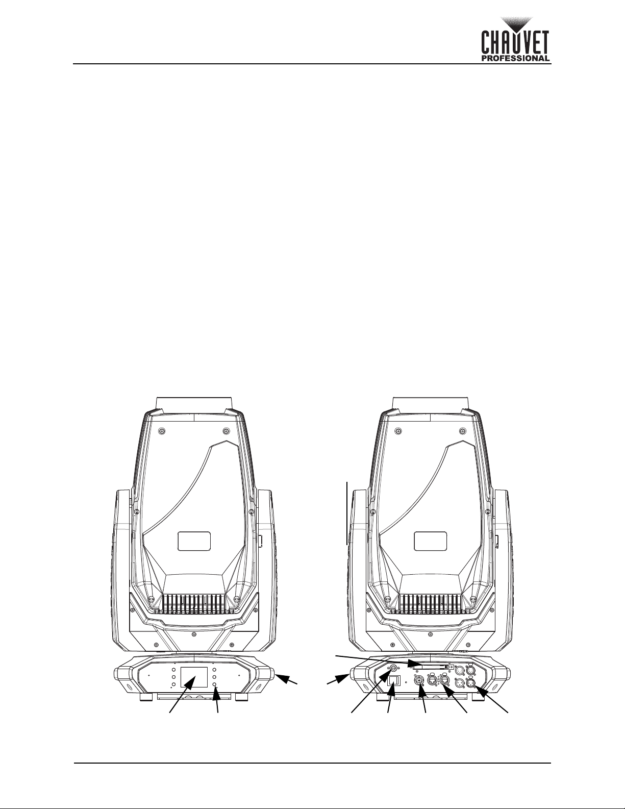
Menu
Buttons
LCD
Display
DMX
In/Out
Power
Switch
Carry
Handle
Power
In
Fuse
Holder
Ethernet
Ports
WDMX
Antenna
2. Introduction
Description
The Maverick MK3 Profile features an output of over 51,000 source lumens and an advanced, 4-blade
shutter frame system with the ability to fully black out and a 120° rotation. Its precision LED optics feature
CMY + CTO color mixing and a fast 9:1 zoom ratio that maintains a flat field of focus even when fully wide.
It also has an adjustable CRI from 73 to 93 CRI for use as a key light for broadcasted events. The
Maverick MK3 Profile offers static, rotating, and animation effects from its 2 gobo wheels (1 rotating, 1
static), animation wheel, 2 independent and overlapping prisms and 2 frost options: super-light and
medium. Controllable with DMX, sACN, Art-Net or W-DMX.
Features
• Full featured 820 W LED yoke profile fixture including CMY+CTO color mixin g, a fou r blade framing
shutter system with rotation, a color wheel, a CRI filter, animation wheel, a 9:1 zoom, two
independently layerable prisms, two frosts, a static and a rotating gobo wheel
• 16-bit dimming of master dimmer for smooth control of fades
• Variable CMY + CTO color mixing system to create a wide pallet of colors
• Independently layerable five facet linear and five facet round prisms for increased prism options
• One rotating and one static gobo wheel for dynamic texture possibilities
• Independent light and medium frosts for beam control
• + or – 60 degree rotation framing shutter system to allow for better framing positioning.
• Animation wheel for enhanced visual effects
• Iris for total beam control
• RDM control over DMX for fixture reporting
• 6° to 54° zoom angle for variable beam sizes
• Three menu presets and preset cross load for decreased shop setup time
• True 1 compatible power input
• Battery backup display with auto-rotate depending on fixture orientation
Product Overview
Maverick MK3 Profile User Manual Rev. 1
Page 3 of 33
Page 8
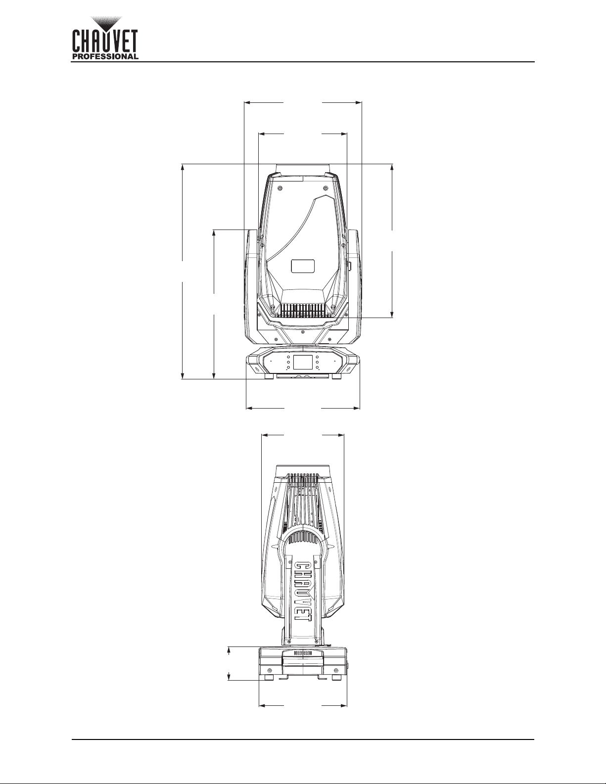
Product Dimensions
21.26 in
540 mm
12.13 in
308 mm
16.10 in
409 mm
29.43 in
748 mm
20.55 in
522 mm
15.55 in
395 mm
11.46 in
291 mm
12.20 in
310 mm
4.61 in
117 mm
Introduction
Page 4 of 33
Maverick MK3 Profile User Manual Rev. 1
Page 9
Setup
3. Setup
AC Power
The Maverick MK3 Profile has an auto-ranging power supply and it can work with an input voltage range of
100 to 240 VAC, 50/60 Hz.
To determine the product’s power requirements (circuit breaker, power outlet, and wiring), use the current
value listed on the label affixed to the product’s back panel, or refer to the product’s specifications chart.
The listed current rating indicates the product’s average current draw under normal conditions.
• Always connect the product to a protected circuit (a circuit breaker or fuse). Make sure
the product has an appropriate electrical ground to avoid the risk of electrocution or
fire.
• To eliminate unnecessary wear and improve its lifespan, during periods of non-use
completely disconnect the product from power via breaker or by unplugging it.
Never connect the product to a rheostat (variable resistor) or dimmer circuit, even if the
rheostat or dimmer channel serves only as a 0 to 100% switch.
AC Plug
The Maverick MK3 Profile comes with a power input cord terminated with a Seetronic Powerkon A
connector on one end and an Edison plug on the other end (U.S. market). If the power input cord that
came with your product has no plug, or if you need the change the plug, use the table below to wire the
new plug.
Connection Wire (U.S.) Wire (Europe) Screw Color
AC Live Black Brown Yellow or Brass
AC Neutral White Blue Silver
AC Ground Green/Yellow Green/Yellow Green
Fuse Replacement
1. Disconnect this product from the power outlet.
2. Using a flat-head screwdriver, unscrew the fuse holder cap from the housing.
3. Remove the blown fuse and replace with another fuse of the same type and rating (F 20 A, 250 V).
4. Screw the fuse holder cap back in place and reconnect power.
Remote Device Management (RDM)
Remote Device Management, or RDM, is a standard for allowing DMX-enabled devices to communicate
bi-directionally along existing DMX cabling. Check the DMX controller’s User Manual or with the
manufacturer as not all DMX controllers have this capability. The Maverick MK3 Profile supports RDM
protocol that allows feedback to make changes to menu map options.
Maverick MK3 Profile User Manual Rev. 1
Page 5 of 33
Page 10
Setup
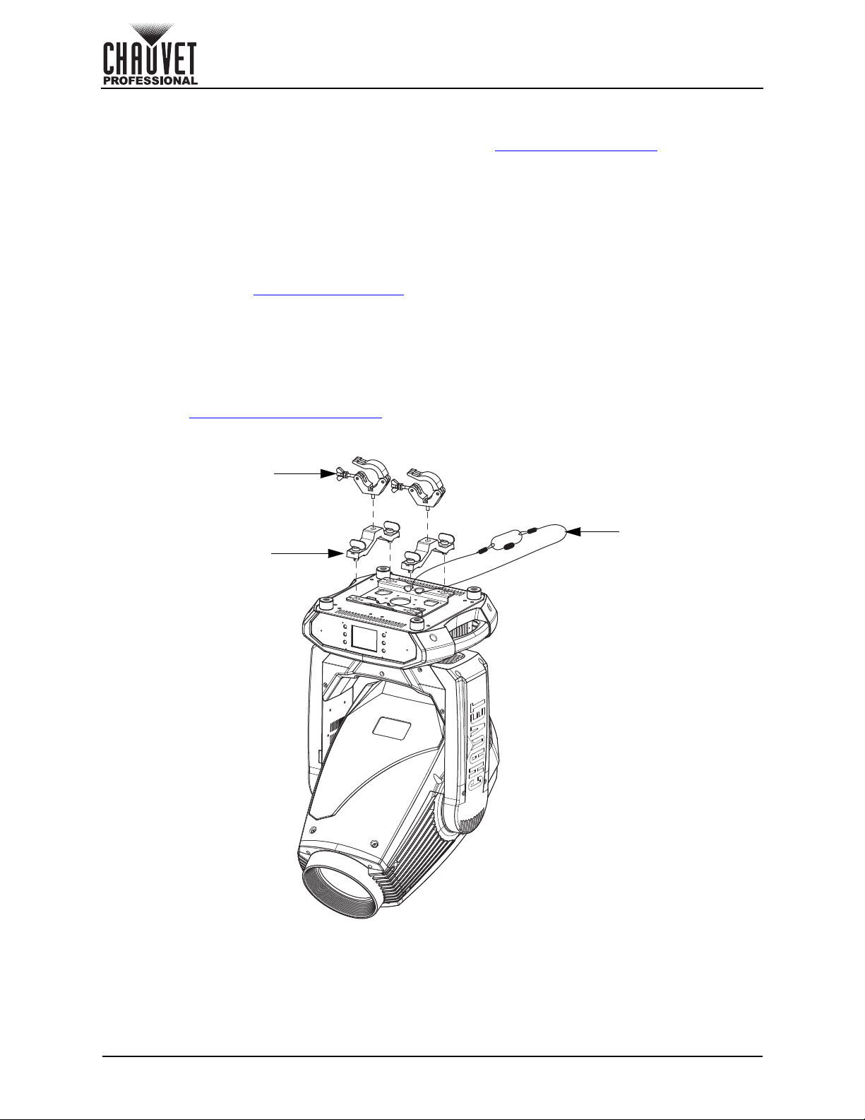
Safety Cable
Mounting Clamp (x2)
Omega Bracket (x2)
Mounting
Before mounting the product, read and follow the safety recommendations indicated in the Safety Notes.
For our CHAUVET Professional line of mounting clamps, go to http://trusst.com/products/
Orientation
Always mount this product in a safe position, making sure there is adequate room for ventilation,
configuration, and maintenance.
Rigging
Chauvet recommends using the following general guidelines when mounting this product.
• Before deciding on a location for the product, make sure there is easy access to the product for
maintenance and programming purposes.
• Make sure that the structure onto which you are mounting the product can support the product’s
weight. See the Technical Specifications
• When mounting the product overhead, always use a safety cable. Mount the product securely to a
rigging point, whether an elevated platform or a truss.
• When rigging the product onto a truss, use a mounting clamp of appropriate weight capacity.
for weight information.
Procedure
The Maverick MK3 Profile comes with a bracket to which you can attach a mounting clamp directly.
Mounting clamps are sold separately. Make sure the clamps are capable of supporting the weight of this
product. Use at least two mounting points per product. For the CHAUVET Professional line of mounting
clamps, go to http://www.trusst.com/products
Mounting Diagram
.
.
Page 6 of 33
Maverick MK3 Profile User Manual Rev. 1
Page 11
Setup
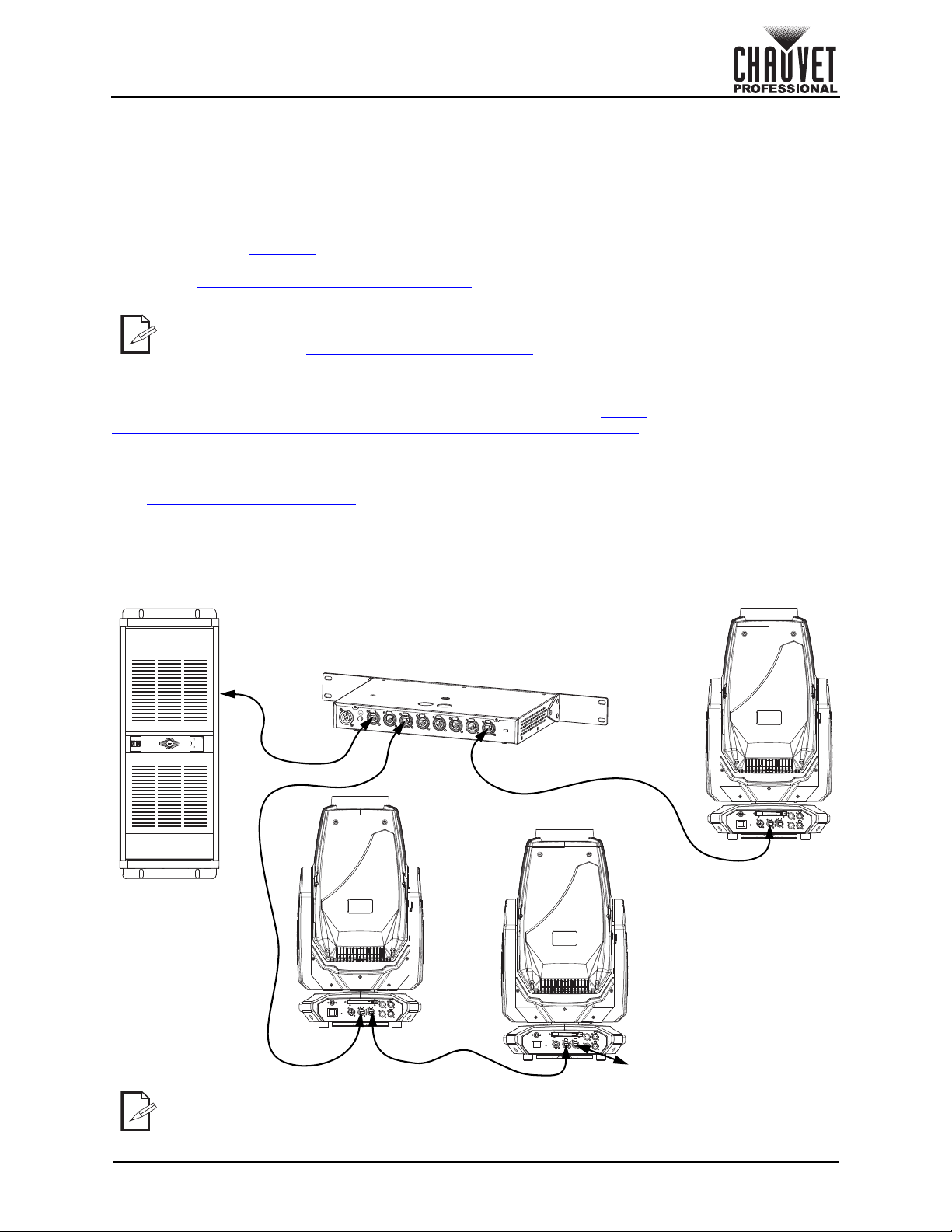
Computer/
Controller
(running Art-Net™
or sACN protocol)
Switch or Router
Maverick MK3 Profile
To other Art-Net™ or sACN devices
Signal Connections
The Maverick MK3 Profile can receive a DMX, Art-Net™, or sACN, signal. The Maverick MK3 Profile has 2
Amphenol XLRnet through ports, and 3- and 5-pin DMX in and out ports. If using other compatible
products with this product, you can control each individually with a single controller.
Control Personalities
The Maverick MK3 Profile uses a 3 or 5-pin DMX data connection, WDMX, Art-Net™, or sACN for its 2
control personalities: Dmx Mode 38 CH and Dmx Mode 54 CH.
• Refer to the Operation chapter to learn how to configure the Maverick MK3 Profile to work in these
personalities.
• The Control Channel Assignments and Values
control personalities.
If you are not familiar with or need more information about DMX standards or the DMX
cables needed to link this product to a DMX controller, download the DMX Primer from the
Chauvet website: www.
chauvetprofessional.com.
DMX Linking
You can link the Maverick MK3 Profile to a DMX controller using a 3 or 5-pin DMX connection or a WDMX
connection. For more information about DMX, read the DMX primer at: https://
www.chauvetprofessional.com/wp-content/uploads/2016/06/DMX_Primer.pdf.
Art-Net™ Connection
Art-Net™ is an Ethernet protocol that uses TCP/IP which transfers a large amount of DMX512 data using
an Amphenol XLRnet RJ45 connection over a large network. An Art-Net™ protocol document is available
from www.chauvetprofessional.com
Art-Net™ designed by and copyright Artistic Licence Holdings Ltd.
.
sACN Connection
Also known as ANSI E1.31, streaming ACN is an Ethernet protocol that uses the layering and formatting of
Architecture for Control Networks to transport DMX512 data over IP or any other ACN compatible network.
Connection Diagram
section provides detailed information regarding the
The three LED indicators in between the ethernet through ports indicate a connection to a
network and activity on that network. They do not indicate whether or not the
Maverick MK3 Profile is receiving a signal from a controller.
Maverick MK3 Profile User Manual Rev. 1
Page 7 of 33
Page 12
Operation
4. Operation
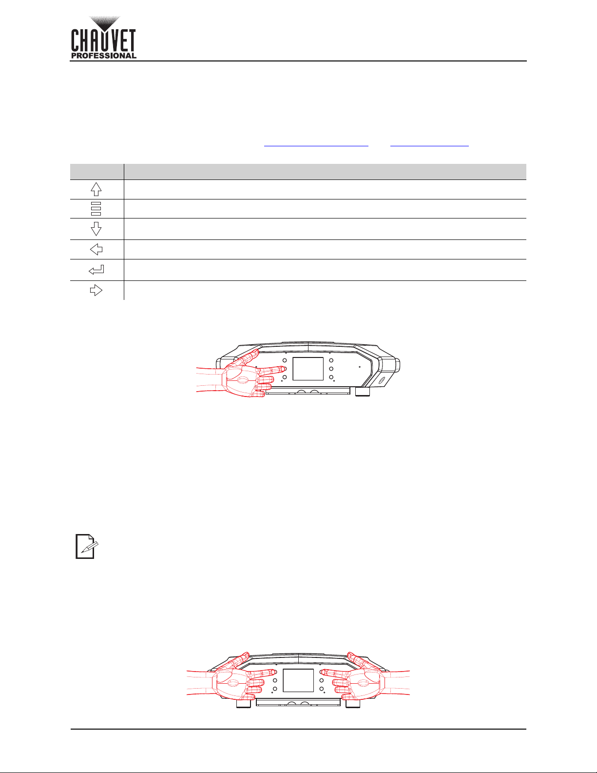
Touchscreen Control Panel
The Maverick MK3 Profile has a touchscreen display as well as 6 control buttons. Navigate the menu
structure by pressing the buttons, touching the images of the buttons on the sides of the display, or
touching the desired menu option on the display directly. The touchscreen can be locked and calibrated
through the Setup options in the menu. (See Touchscreen Calibration
Control Panel Description
Button Function
Navigates upwards through the menu list or increases the numeric value when in a function
Exits from the current menu or function
Navigates downwards through the menu list or decreases the numeric value when in a
function
Navigates leftwards through the menu list
Enables the currently displayed menu or sets the currently selected value into the selected
function
Navigates rightwards through the menu list
Battery Powered Display
The Maverick MK3 Profile has a battery powered display which enables access to the menu when the
product is powered off. Press and hold <MENU> until the display activates (approximately 15 seconds).
and Touchscreen Lock.)
Home Screen
The Maverick MK3 Profile has a home screen that shows the current control protocols, personalities,
starting addresses, IP addresses, and universes. To see the home screen, press <MENU> repeatedly until
it shows on the display. From the home screen, touch any of the displayed control settings to immediately
jump to that part of the menu, such as the personality, starting address, or universe, or press <ENTER> to
reach the main menu.
Control Panel Lock
The setting locks or unlocks the control panel.
1. Go to the Settings main level.
2. Select the Lock Screen option.
3. Select NO (control panel stays unlocked) or YES (locks control panel).
When the control panel lock is activated, the product will prompt for the passcode in order
to access the menu. Enter the passcode as described below.
Passcode
After being prompted to enter the passcode, press <UP>, <DOWN>, <UP>, <DOWN>, <ENTER>.
Followspot Mode
The followspot mode disables the pan and tilt motors, allowing the output of the product to be aimed by
hand. To enable the followspot mode of the Maverick MK3 Profile, hold <UP> and <LEFT> while the
product is powering on. When the product is turned off and back on, the pan and tilt will return to normal
function.
Page 8 of 33
Maverick MK3 Profile User Manual Rev. 1
Page 13

Operation
Menu Map
Main Level Programming Levels Description
Address 001–475 Sets the starting address
Manual Manually set IP address
Network
Setup
Personality
Settings
IP Mode
Universe
Ip _ _ _._ _ _._ _ _._ _ _
SubMask _ _ _._ _ _._ _ _._ _ _
Dmx Mode 38 CH
Dmx Mode 54 CH
Control Mode
Pan Reverse
Tilt Reverse
Screen Reverse
Pan Angle
Tilt Angle
BL. O. P/T Move
BL. O. Color Move
BL. O. Gobo Move
Calibration
Touchscreen Lock
000–255 (Art-Net™)
DHCP Network sets IP address
Static Product sets IP address
001–256 (sACN)
YES
NO
YES
NO
DMX
WDMX
ArtNet
sACN
NO Normal pan
YES Reversed pan
NO Normal tilt
YES Reversed tilt
NO Normal display
YES Inverted display
AUTO Automatic display orientation
540 540° pan range
360 360° pan range
180 180° pan range
270 270° tilt range
180 180° tilt range
90 90° tilt range
NO
YES Blackout while panning/tilting
NO
YES
NO
YES
NO Calibration disabled
YES Calibration enabled
NO Touch screen enabled
YES Touch screen disabled
Sets the universe
Sets the IP address in
Manual mode
Sets the Subnet Mask in
Manual mode
Selects the 38-channel mode
Selects the 54-channel mode
Sets the control protocol
Do not black out while
panning/tilting
Do not black out while color
wheel moving
Blackout while color wheel
moving
Do not black out while gobo
wheels moving
Blackout while gobo wheels
moving
Maverick MK3 Profile User Manual Rev. 1
Page 9 of 33
Page 14

Main Level Programming Levels Description
Settings
(cont.)
Lock Screen
Swap XY
WDMX Reset
Backlight Timer
Loss of Data
Fans
Dimmer Curve
PWM Option
Preset Select
Preset Sync
Reset
Function
Factory Settings
Pan/Tilt
Iris/Prism
Color/CMY/Blade
Gobo/Gobo Rotate
Frost/Animation
All
NO
YES
NO Do not swap pan and tilt
YES
NO Do not reset WDMX
YES Reset WDMX
30S
1M
5M
ON Display stays on
Hold Holds last signal received
Close Blacks out fixture
Auto
Full Fan speed set on high
ECO Quiet mode
Linear
Square
I Squa
SCurve
600Hz
1200Hz
4000Hz
6000Hz
15000Hz
PRESET A
PRESET B
PRESET C
NO Allows recorded preset menu
YES
NO/YES
NO
YES
Lock the buttons and touch
screen. Passcode: 0920
Pan controls tilt, tilt controls
pan
Display turns off after 30
seconds
Display turns off after 1
minute
Display turns off after 5
minutes
Fan speed according to
product temperature
Set the dimmer curve
Sets the Pulse Width
Modulation frequency
Recorded preset menu
options
options to be transferred to
other Maverick MK3 Profile
fixtures in the DMX daisy
chain
Reset individual functions or
all functions from start-up
Reset to factory default
settings
Operation
Page 10 of 33
Maverick MK3 Profile User Manual Rev. 1
Page 15

Operation
Main Level Programming Levels Description
Auto Test Auto test all functions
Pan
Pan Fine
Tilt
Tilt Fine
P/T Speed
Dimmer
Dimmer Fine
Shutter
Virtual Shaking
Cyan
Magenta
Yellow
CTO
Color
Gobo
Gobo Rotate
Gobo Index
Gobo2
Animation
Animation Rotate
Blade1- 1
Test
Manual Test
Blade1- 1 Fine
Blade1- 2
Blade1- 2 Fine
Blade2- 1
Blade2- 1 Fine
Blade2- 2
Blade2- 2 Fine
Blade3- 1
Blade3- 1 Fine
Blade3- 2
Blade3- 2 Fine
Blade4- 1
Blade4- 1 Fine
Blade4- 2
Blade4- 2 Fine
Blade Rotate
Blade. Rota Fine
Focus
Focus Fine
Focus Auto
Zoom
Zoom Fine
Prism
Prism Rotate
000–255
Manually control and test all
settings through the control
panel
Maverick MK3 Profile User Manual Rev. 1
Page 11 of 33
Page 16

Main Level Programming Levels Description
Prism2
Prism2 Rotate
Iris
Test (cont.)
Information
Manual Test
(cont.)
CMY Macro Speed
Fixture
Information
Fan
Information
Error Information _ _ _ _ _
Channel
Information
Frost
Frost2
CRI Filter
CMY Macro
Special Function
Ver V_ Shows firmware version
Running Mode _ _ _ Shows current running mode
DMX Address _ _ _
Tem perature _ _ _
Fixture Hours _ _ _ _ _
Ip _ _ _ _ _ _ _ _ Shows current IP address
SubMask _ _ _ _ _ _ _ _ Shows current Subnet Mask
MAC _ _ _ _ _ _ _ _ Shows current MAC address
head Fan1 Speed _ _ _ _
head Fan2 Speed _ _ _ _
head Fan3 Speed _ _ _ _
head Fan4 Speed _ _ _ _
head Fan5 Speed _ _ _ _
head Fan6 Speed _ _ _ _
Frequency
Pan
Pan Fine
Tilt
Tilt Fine
P/T Speed
Dimmer
Dimmer Fine
Shutter
Virtual Shaking
Cyan
Magenta
Yellow
CTO
Color
Gobo
Gobo Rotate
Gobo Index
Gobo2
000–255
_ _ _
Manually control and test all
settings through the control
panel
Shows current starting
address
Shows current product
temperature in °C
Shows number of hours
product has been powered
on
Shows speed of head fans in
rpm
Shows any errors, or No
Error!
Shows all current values from
input signals, 000–255
Operation
Page 12 of 33
Maverick MK3 Profile User Manual Rev. 1
Page 17

Operation
Main Level Programming Levels Description
Animation
Animation Rotate
Blade1- 1
Blade1- 1 Fine
Blade1- 2
Blade1- 2 Fine
Blade2- 1
Blade2- 1 Fine
Blade2- 2
Blade2- 2 Fine
Blade3- 1
Blade3- 1 Fine
Blade3- 2
Blade3- 2 Fine
Blade4- 1
Blade4- 1 Fine
Blade4- 2
Information
(cont.)
Channel
Information
(cont.)
Blade4- 2 Fine
Blade Rotate
Blade. Rota Fine
Focus
Focus Fine
Focus Auto
Zoom
Zoom Fine
Prism
Prism Rotate
Prism2
Prism2 Rotate
Iris
Frost
Frost2
CRI Filter
CMY Macro
CMY Macro Speed
Special Function
_ _ _
Shows all current values from
input signals, 000–255
Maverick MK3 Profile User Manual Rev. 1
Page 13 of 33
Page 18

Operation
Configuration (DMX, Art-Net™, sACN)
Use control configurations to operate the product with a DMX, Art-Net™, or sACN controller.
Control Mode
The Maverick MK3 Profile works with wired DMX, WDMX, Art-Net™, and sACN control signals. To select
which protocol to use:
1. Go to the Settings main level.
2. Select the Control Mode option.
3. Select the desired protocol, from DMX, WDMX, ArtNet, or sACN.
• See the WDMX Reset
• See the Network Setup
Control Personalities
To set the control personality:
1. Go to the Personality main level.
2. Select the desired personality, from Dmx Mode 38 CH or Dmx Mode 54 CH.
• See the Starting Address
personality.
• Make sure that the starting addresses on the various products do not overlap due to the new
personality setting.
Starting Address
Each product will respond to a unique starting address from the controller. All products with the same
starting address will respond in unison. To set the starting address:
1. Go to the Address main level.
2. Select the starting address (001–475).
• The highest recommended starting address for Dmx Mode 38 CH is 475.
• The highest recommended starting address for Dmx Mode 54 CH is 459.
Network Setup
The Network Setup settings control the IP address, subnet mask, and universe of the product.
IP Mode
To choose how the IP address is set:
1. Go to the Network Setup main level.
2. Select the IP Mode option.
3. Select the desired IP mode, from Manual (to set a custom IP address), DHCP (the IP address is
assigned by the connected network), or Static (the product uses a default, preset IP address).
Universe
To assign an Art-Net™ or sACN universe to the Maverick MK3 Profile:
1. Go to the Network Setup main level.
2. Select the Universe option.
3. Set the universe, from 000–255 (for Art-Net™) or from 001–256 (for sACN).
Manual IP Address
To set the IP address when the IP Mode is set to Manual:
1. Go to the Network Setup main level.
2. Select the Ip option.
3. Set the 4 values of the IP address from 000–255.
Subnet Mask
To set the subnet mask:
1. Go to the Network Setup main level.
2. Select the SubMask option.
3. Set the 4 values of the subnet mask from 000–255.
section for further setup of WDMX.
section for further setup of ethernet protocols (Art-Net™ or sACN).
section for the highest starting address you can select for each
Page 14 of 33
Maverick MK3 Profile User Manual Rev. 1
Page 19

Operation
Control Channel Assignments and Values
Dmx Mode 54 CH
Channel Function Value Percent/Setting
1Pan 000 255 0–100%
2Fine Pan 000 255 Fine control (16-bit)
3Tilt 000 255 0–100%
4 Fine Tilt 000 255 Fine control (16-bit)
5 Pan/Tilt Speed 000 255 Fast to slow
6 Dimmer 000 255 0–100%
7 Fine Dimmer 000 255 Fine control (16-bit)
000 003 Closed
004 007 Open
8Shutter
9 Virtual Strobe
10 Cyan 000 255 0–100%
11 Magenta 000 255 0–100%
12 Yellow 000 255 0–100%
13 CTO 000 255 0–100%
14 Color Wheel
15 Gobo Wheel 1
008 076 Strobe, slow to fast
077 145 Pulse strobe, slow to fast
146 215 Random strobe, slow to fast
216 255 Open
000 001 No function
002 128 Shaking strobe, slow to fast
129 255 Fading shake, slow to fast
000 007 Open
008 015 Red
016 023 Orange
024 031 Green
032 039 Yellow
040 047 Dark blue
048 059 8000K CTB
060 187 Color wheel indexing
188
219 Color scroll, fast to slow
220 223 Stop
224 255 Reverse color scroll, slow to fast
000 007 Open
008 015 Gobo 1 (Sail Boats)
016 023 Gobo 2 (Radial Dot)
024 031 Gobo 3 (Mower Blade)
032 039 Gobo 4 (Bolts)
040 047 Gobo 5 (Shower Glass)
048 055 Gobo 6 (Ballistic Clouds)
056 063 Gobo 7 (Four Eyes)
064 071 Gobo 7 shaking
072 079 Gobo 6 shaking
080 087 Gobo 5 shaking
088 095 Gobo 4 shaking
096 103 Gobo 3 shaking
104 111 Gobo 2 shaking
112 119 Gobo 1 shaking
120 127 Open
128 191 Gobo scroll, slow to fast
192 255 Reverse gobo scroll, slow to fast
Maverick MK3 Profile User Manual Rev. 1
Page 15 of 33
Page 20

Channel Function Value Percent/Setting
000 063 Rotating gobo index
064 145 Gobo rotation, fast to slow
16 Gobo 1 Rotate
17 Gobo Wheel 1 Indexing 000 255 Fine control (16-bit)
18 Gobo Wheel 2
19 Animation Wheel 000 255 Animation effect, 0–100%
20 Animation Wheel Rotate
21 Blade 1-1 000 255 0–100%
22 Blade 1-1 Fine 000 255 Fine control (16-bit)
23 Blade 1-2 000 255 0–100%
24 Blade 1-2 Fine 000 255 Fine control (16-bit)
25 Blade 2-1 000 255 0–100%
26 Blade 2-1 Fine 000 255 Fine control (16-bit)
27 Blade 2-2 000 255 0–100%
28 Blade 2-2 Fine 000 255 Fine control (16-bit)
29 Blade 3-1 000 255 0–100%
30 Blade 3-1 Fine 000 255 Fine control (16-bit)
31 Blade 3-2 000 255 0–100%
32 Blade 3-2 Fine 000 255 Fine control (16-bit)
33 Blade 4-1 000 255 0–100%
34 Blade 4-1 Fine 000 255 Fine control (16-bit)
35 Blade 4-2 000 255 0–100%
36 Blade 4-2 Fine 000 255 Fine control (16-bit)
37 Frame Rotate 000 255 0–100%
38 Frame Fine Rotate 000 255 Fine control (16-bit)
39 Focus 000 255 0–100%
40 Fine Focus 000 255 Fine control (16-bit)
146 149 Stop
150 231 Reverse gobo rotation, slow to fast
232 255 Bounce effect, short to long
000 005 Open
006 011 Gobo 1 (Beam)
012 017 Gobo 2 (Bars)
018 023 Gobo 3 (Circles)
024 029 Gobo 4 (Breakup)
030 035 Gobo 5 (Dots)
036 041 Gobo 6 (Circuits)
042 047 Gobo 7 (Triangles)
048 053 Gobo 8 (Forest)
054 063 Gobo 9 (Rainbows)
064 069 Gobo 9 shaking
070 075 Gobo 8 shaking
076 081 Gobo 7 shaking
082 087 Gobo 6 shaking
088 093 Gobo 5 shaking
094 099 Gobo 4 shaking
100 105 Gobo 3 shaking
106 111 Gobo 2 shaking
112 117 Gobo 1 shaking
118 127 Open
128 191 Gobo scroll, slow to fast
192 255 Reverse gobo scroll, slow to fast
000 124 Animation wheel rotation, fast to slow
125
130 Stop
131 255 Reverse animation wheel, slow to fast
Operation
Page 16 of 33
Maverick MK3 Profile User Manual Rev. 1
Page 21

Operation
Channel Function Value Percent/Setting
000 010 No function
011 030 0–5 m
031 050 6 m
051 070 7 m
071 090 8 m
41 Auto Focus
42 Zoom 000 255 0–100%
43 Fine Zoom 000 255 Fine control (16-bit)
44 Prism 1
45 Prism 1 Rotate
46 Prism 2
47 Prism 2 Rotate
48 Iris
49 Frost 1 000
50 Frost 2 000 255 0–100%
51 CRI Filter
52 CMY Macro
53 CMY Macro Speed 000 255 CMY macro speed, fast to slow
091 110 9 m
111 130 10 m
131 150 12.5 m
151 170 15 m
171 190 17.5 m
191 210 20–60 m
211 255 Auto-detect distance
000 004 No function
005 255 Prism effect 1
000 127 Rotating prism 1 index
128 189 Prism 1 rotation, fast to slow
190 193 Stop
194 255 Reverse prism 1 rotation, slow to fast
000 004 No function
005 255 Prism effect 2
000 127 Rotating prism 2 index
128 189 Prism 2 rotation, fast to slow
190 193 Stop
194 255 Reverse prism 2 rotation, slow to fast
000 063 Big to small
064 127 Auto change, slow to fast
128 191 Slow expand, fast shrink (slow to fast)
192 255 Slow shrink, fast expand (slow to fast)
255 0–100%
000 004 No function
005 255 CRI filter
000 009 No function
010 255 CMY macro
Maverick MK3 Profile User Manual Rev. 1
Page 17 of 33
Page 22

Channel Function Value Percent/Setting
000 007 No function
008 015 XY blackout
016 023 C blackout
024 031 G blackout
032 039 XY/C blackout
040 047 XY/G blackout
048 055 XY/C/G blackout
056 095 No function
096 103 X reset
104 111 Y reset
112 119 Color reset
120 127 Gobo wheels and rotation reset
128 135 No function
136 143 Prisms reset
144 151 Framing shutter reset
54 Control
152 159 All reset
160 167 Iris reset
168 175 Frost reset
176 183 Zoom reset
184 191 CMY reset
192 199 Fan ECO mode
200 207 Fan full speed
208 215 Fan auto
216 220 No function
221 225 Iris fast mode
226 230 Iris smooth mode
231 235 XY swap on
236 240 XY swap off
241 245 No function
246 250 XY smooth mode
251 255 XY fast mode
Operation
Dmx Mode 38 CH
Channel Function Value Percent/Setting
1Pan 000 255 0–100%
2Fine Pan 000 255 Fine control (16-bit)
3Tilt 000 255 0–100%
4 Fine Tilt 000 255 Fine control (16-bit)
5 Pan/Tilt Speed 000 255 Fast to slow
6 Dimmer 000 255 0–100%
000 003 Closed
004 007 Open
7Shutter
8 Virtual Strobe
9Cyan 000 255 0–100%
10 Magenta 000 255 0–100%
11 Yellow 000 255 0–100%
12 CTO 000 255 0–100%
Page 18 of 33
008 076 Strobe, slow to fast
077 145 Pulse strobe, slow to fast
146 215 Random strobe, slow to fast
216 255 Open
000 001 No function
002 128 Shaking strobe, slow to fast
129 255 Fade in/out, slow to fast
Maverick MK3 Profile User Manual Rev. 1
Page 23

Operation
Channel Function Value Percent/Setting
000 007 Open
008 015 Red
016 023 Orange
024 031 Green
032 039 Yellow
13 Color Wheel
14 Gobo Wheel 1
15 Gobo 1 Rotate
040 047 Dark blue
048 059 8000K CTB
060 187 Split colors
188 219 Color scroll, fast to slow
220 223 Stop
224 255 Reverse color scroll, slow to fast
000 007 Open
008 015 Gobo 1 (Sail Boats)
016 023 Gobo 2 (Radial Dot)
024 031 Gobo 3 (Mower Blade)
032 039 Gobo 4 (Bolts)
040 047 Gobo 5 (Shower Glass)
048 055 Gobo 6 (Ballistic Clouds)
056 063 Gobo 7 (Four Eyes)
064 071 Gobo 7 shaking
072 079 Gobo 6 shaking
080 087 Gobo 5 shaking
088 095 Gobo 4 shaking
096 103 Gobo 3 shaking
104 111 Gobo 2 shaking
112 119 Gobo 1 shaking
120 127 Open
128 191 Gobo scroll, slow to fast
192 255 Reverse gobo scroll, slow to fast
000 063 Rotating gobo index
064 145 Gobo rotation, fast to slow
146 149 Stop
150 231 Reverse gobo rotation, slow to fast
232 255 Bounce effect
Maverick MK3 Profile User Manual Rev. 1
Page 19 of 33
Page 24

Channel Function Value Percent/Setting
000 005 Open
006 011 Gobo 1 (Beam)
012 017 Gobo 2 (Bars)
018 023 Gobo 3 (Circles)
024 029 Gobo 4 (Breakup)
030 035 Gobo 5 (Dots)
036 041 Gobo 6 (Circuits)
042 047 Gobo 7 (Triangles)
048 053 Gobo 8 (Forest)
054 063 Gobo 9 (Rainbows)
16 Gobo Wheel 2
17 Animation Wheel 000 255 Animation effect
18 Animation Wheel Rotate
19 Blade 1-1 000 255 0–100%
20 Blade 1-2 000 255 0–100%
21 Blade 2-1 000 255 0–100%
22 Blade 2-2 000
23 Blade 3-1 000 255 0–100%
24 Blade 3-2 000 255 0–100%
25 Blade 4-1 000 255 0–100%
26 Blade 4-2 000 255 0–100%
27 Frame Rotate 000 255 0–100%
28 Focus 000 255 0–100%
29 Zoom 000 255 0–100%
30 Prism 1
31 Prism 1 Rotate
32 Prism 2
33 Prism 2 Rotate
34 Iris
35 Frost 1 000 255 0–100%
064 069 Gobo 9 shaking
070 075 Gobo 8 shaking
076 081 Gobo 7 shaking
082 087 Gobo 6 shaking
088 093 Gobo 5 shaking
094 099 Gobo 4 shaking
100 105 Gobo 3 shaking
106 111 Gobo 2 shaking
112 117 Gobo 1 shaking
118 127 Open
128 191 Gobo scroll, slow to fast
192 255 Reverse gobo scroll, slow to fast
000 255 Animation wheel rotation, fast to slow
000 255 Stop
000 255 Reverse animation wheel, slow to fast
255 0–100%
000 004 No function
005 255 Prism effect 1
000 127 Rotating prism 1 index
128 189 Prism 1 rotation, fast to slow
190 193 Stop
194 255 Reverse prism 1 rotation, slow to fast
000 004 No function
005 255 Prism effect 2
000 127 Rotating prism 2 index
128 189 Prism 2 rotation, fast to slow
190 193 Stop
194 255 Reverse prism 2 rotation, slow to fast
000 063 Big to small
064 127 Auto change, slow to fast
128 191 Slow zoom out, fast zoom in (slow to fast)
192 255 Slow zoom in, fast zoom out (slow to fast)
Operation
Page 20 of 33
Maverick MK3 Profile User Manual Rev. 1
Page 25

Operation
Channel Function Value Percent/Setting
36 Frost 2 000 255 0–100%
37 CRI Filter
38 Control
000 004 No function
005 255 CRI filter
000 007 No function
008 015 XY blackout
016 023 C blackout
024 031 G blackout
032 039 XY/C blackout
040 047 XY/G blackout
048 055 XY/C/G blackout
056 095 No function
096 103 X reset
104 111 Y reset
112 119 Color reset
120 127 Gobo wheels and rotation reset
128 135 No function
136 143 Prisms reset
144 151 Framing shutter reset
152 159 All reset
160 167 Iris reset
168 175 Frost reset
176 183 Zoom reset
184 191 CMY reset
192 199 Fan low speed
200 207 Fan full speed
208 215 Fan auto
216 220 No function
221 225 Iris fast mode
226 230 Iris smooth mode
231 235 XY swap on
236 240 XY swap off
241 245 No function
246
250 XY smooth mode
251 255 XY fast mode
Maverick MK3 Profile User Manual Rev. 1
Page 21 of 33
Page 26

Operation
Configuration (Settings)
Pan Reverse
To set the orientation of the pan:
1. Go to the Settings main level.
2. Select the Pan Reverse option.
3. Select from NO (normal pan motion), or YES (reversed pan motion).
Tilt Reverse
To set the orientation of the tilt:
1. Go to the Settings main level.
2. Select the Tilt Reverse option.
3. Select from NO (normal tilt motion), or YES (reversed tilt motion).
Screen Reverse
To set the orientation of the display:
1. Go to the Settings main level.
2. Select the Screen Reverse option.
3. Select from NO (right-side up), YES (upside-down), or AUTO (changes depending on the
orientation of the product).
Pan Angle
To set the maximum angle of the pan:
1. Go to the Settings main level.
2. Select the Pan Angle option.
3. Select from 540 (540°), 360 (360°), or 180 (180°).
Tilt Angle
To set the maximum angle of the tilt:
1. Go to the Settings main level.
2. Select the Tilt Angle option.
3. Select from 270 (270°), 180 (180°), or 90 (90°).
Blackout on Movement
To set the Maverick MK3 Profile to black out on pan or tilt movement, color wheel movement, or gobo
wheel movement:
1. Go to the Settings main level.
2. Select the BL. O. P/T Move (blackout on pan or tilt movement), BL. O. Color Move (blackout on
color wheel movement), or BL. O. Gobo Move (blackout on gobo wheel movement) option.
3. Select from NO (no blackout on selected movement), or YES (blackout during the selected
movement).
Touchscreen Calibration
To calibrate the touchscreen:
1. Go to the Settings main level.
2. Select the Calibration option.
3. Select from NO (do not calibrate), or YES (calibrate).
4. Follow the instructions on the display.
Touchscreen Lock
To lock the touchscreen and limit the display to operation by the menu buttons:
1. Go to the Settings main level.
2. Select the Touchscreen Lock option.
3. Select from NO (do not lock the touchscreen), or YES (lock the touchscreen).
Swap Pan and Tilt
To swap the pan and tilt controls for each other:
1. Go to the Settings main level.
2. Select the Swap XY option.
3. Select from NO (do not swap), or YES (swap so pan controls tilt and tilt controls pan).
Page 22 of 33
Maverick MK3 Profile User Manual Rev. 1
Page 27

Operation
WDMX Reset
To reset the WDMX connection and allow the Maverick MK3 Profile to connect to a WDMX transmitter:
1. Go to the Settings main level.
2. Select the WDMX Reset option.
3. Select from NO (do not reset), or YES (reset the WDMX connection).
Follow instructions in the manual or guide for the WDMX controller being used to connect
it to the receiver in the Maverick MK3 Profile.
Display Backlight Timer
To set the length of time before an inactive display will turn off:
1. Go to the Settings main level.
2. Select the Backlight Timer option.
3. Select the length of the backlight timer, from 30S (30 seconds), 1M (1 minute), 5M (5 minutes), or
ON (always on).
Loss of Data
To set how the product reacts to a loss in control signal data:
1. Go to the Settings main level.
2. Select the Los of Data option.
3. Select from Hold (holds the last values received before signal loss), or Close (blacks out the
product).
Fan Mode
To set the fan speed mode:
1. Go to the Settings main level.
2. Select the Fans option.
3. Select the fan mode, from Auto (fan speed adjusts to product temperature), Full (fan speed at
maximum), or ECO (quiet mode).
Dimmer Curve
To set the dimmer curve:
1. Go to the Settings main level.
2. Select the Dimmer Curve option.
3. Select the dimmer curve, from Linear, Square, I Squa, or SCurve.
Pulse Width Modulation
To adjust the frequency of the pulse width modulation:
1. Go to the Settings main level.
2. Select the PWM Option option.
3. Select the frequency, from 600Hz, 1200Hz, 2000Hz, 4000Hz, 6000Hz, or 15000Hz.
Preset Selection
To select a preset configuration of menu options:
1. Go to the Settings main level.
2. Select the Preset Select option.
3. Select from PRESET A (default), PRESET B, or PRESET C.
• Changes to settings automatically save to the currently selected Preset.
• If no Preset has been selected, changes to settings save to PRESET A.
• After selecting a Preset, the product will restart.
Preset Synchronization
To transfer saved Presets from one Maverick MK3 Profile to another:
1. Connect the Maverick MK3 Profile products to receive the Presets by a DMX daisy chain.
2. Make the Maverick MK3 Profile with the Presets to transfer the first in the DMX daisy chain.
3. Power on all of the products.
4. Set all of the products to a Control Mode
5. On the Maverick MK3 Profile with the Presets, go to the Settings main level.
6. Select the Preset Sync option.
7. Select NO (to cancel) or YES (to transfer the Presets to the connected products).
• All menu configurations are transferred except for the IP address.
• ONLY connect Maverick MK3 Profile products for this function!
Maverick MK3 Profile User Manual Rev. 1
other than WDMX. (DMX, ArtNet, or sACN)
Page 23 of 33
Page 28

Operation
Reset Function
To reset specific functions or the entire product:
1. Go to the Settings main level.
2. Select the Reset Function option.
3. Select the functions to reset, from:
• Pan/Tilt
•Iris/Prism
• Color/CMY/Blade
• Gobo/Gobo Rotate
• Frost/Animation
or
•All
4. Select NO (to cancel) or YES (to reset the selected functions).
Factory Reset
To reset the product to factory settings:
1. Go to the Settings main level.
2. Select the Factory Reset option.
3. Select NO (to cancel) or YES (to reset the product configuration).
Test Mode
Auto Test
To have the Maverick MK3 Profile automatically test all functions one after the other:
1. Go to the Tes t main level.
2. Select the Auto Test option.
Manual Test
To manually test an individual function of the Maverick MK3 Profile:
1. Go to the Tes t main level.
2. Select the Manual Test option.
3. Select a function to test, from Pan, Pan Fine, Tilt, Tilt Fine, P/T Speed, Dimmer, Dimmer Fine,
Shutter, Virtual Shaking, Cyan, Magenta, Yellow, CTO, Color, Gobo, Gobo Rotate, Gobo
Index, Gobo2, Animation, Animation Rotate, Blade1- 1, Blade1- 1 Fine, Blade1- 2, Blade1- 2
Fine, Blade2- 1, Blade2- 1 Fine, Blade2- 2, Blade2- 2 Fine, Blade3- 1, Blade3- 1 Fine, Blade32, Blade3- 2 Fine, Blade4- 1, Blade4- 1 Fine, Blade4- 2, Blade4- 2 Fine, Blade Rotate, Blade.
Rota Fine, Focus, Focus Fine, Focus Auto, Zoom, Zoom Fine,
Prism2 Rotate, Iris, Frost, Frost2, CRI Filter, CMY Macro, CMY Macro Speed, or Special
Function.
4. Increase or decrease the value of the selected function from 000–255 to test it.
Prism, Prism Rotate, Prism2,
System Information
The information section of the menu displays statistics and the current status of the product’s various
functions. To view these information sections:
1. Go to the Information main level.
2. Select which information to view, from Fixture Information (shows the firmware version, running
mode, addresses, temperature, and running time), Fan Information (shows the speed of the fans
in rotations per minute (rpm)), Error Information (shows any error or No Error!), or Channel
Information (shows the current values of all signal input channels).
3. If necessary, scroll up and down to view all information available in the selected option.
Offset Mode (Zero Adjust)
The Offset mode provides fine adjustments for the home position of every moving part in the optical path
as well as the pan and tilt movements. To adjust these options and prevent borders showing or reduction of
the light output:
1. From the main level screen, press and hold <MENU> until the passcode screen appears.
2. Enter the passcode: 2323 and press <ENTER>.
3. Select the “zero” position to adjust, from PA N , TILT, COLOR, GOBO, GOBO ROTATE, GOBO2,
ANIMATION, FOCUS-GOBO, FOCUS-GOBO2, ZOOM, PRISM, PRISM2, PRISM ROT, IRIS,
FROST, FROST2, CRI Filter, CYAN, MAGENTA, YELLOW, CTO, BLADE1- 1, BLADE1- 2,
BLADE2- 1, BLADE2- 2, BLADE3- 1, BLADE3- 2, BLADE4- 1, BLADE4- 2, BLADE ROTATE,
DIMMER1, DIMMER2, DIMMER3, MAC4, MAC5, or MAC6.
4. Adjust the “zero” position for the selected function from 000–255.
Page 24 of 33
Maverick MK3 Profile User Manual Rev. 1
Page 29

Operation
Web Server
The Maverick MK3 Profile Web Server can be accessed by any computer on the same network as the
product. It allows network access to system information, settings such as control setup, manual testing of
all functions, firmware updates, and the ability to change the Web Server password.
1. Connect the product to power, and set the Control Mode
2. Connect the product to a Windows computer with a network cable.
3. On the computer, set the first value of the IP address of the new network to match the first value of
the IP address of the product. The IP address of the product is displayed on the Home Screen
4. Enter the IP address of the product into the URL bar of a web browser on the computer.
5. Enter both the User Name and Password as admin to log in.
Information
The Information page on the Web Server displays the current settings and the system information of the
Maverick MK3 Profile.
Setup
The Setup page on the Web Server provides options for control, similar to the Setup menu on the product.
Click Save Settings to send the new configuration to the product.
Manual Test
The Manual Test page on the Web Server allows all output functions of the product to be controlled through
the browser. To set all functions back to default, click Reset.
Firmware Update
The Upgrade page on the Web Server allows the product to be updated with the latest firmware. Go to
https://www.chauvetprofessional.com
Security
The Security page on the Web Server gives the option to change the password to the connected product’s
web server. Enter the old password (admin, by default) and the new password twice, then click Save
Settings to change the password.
to download firmware updates.
to ArtNet and the IP Mode to Static.
.
Maverick MK3 Profile User Manual Rev. 1
Page 25 of 33
Page 30

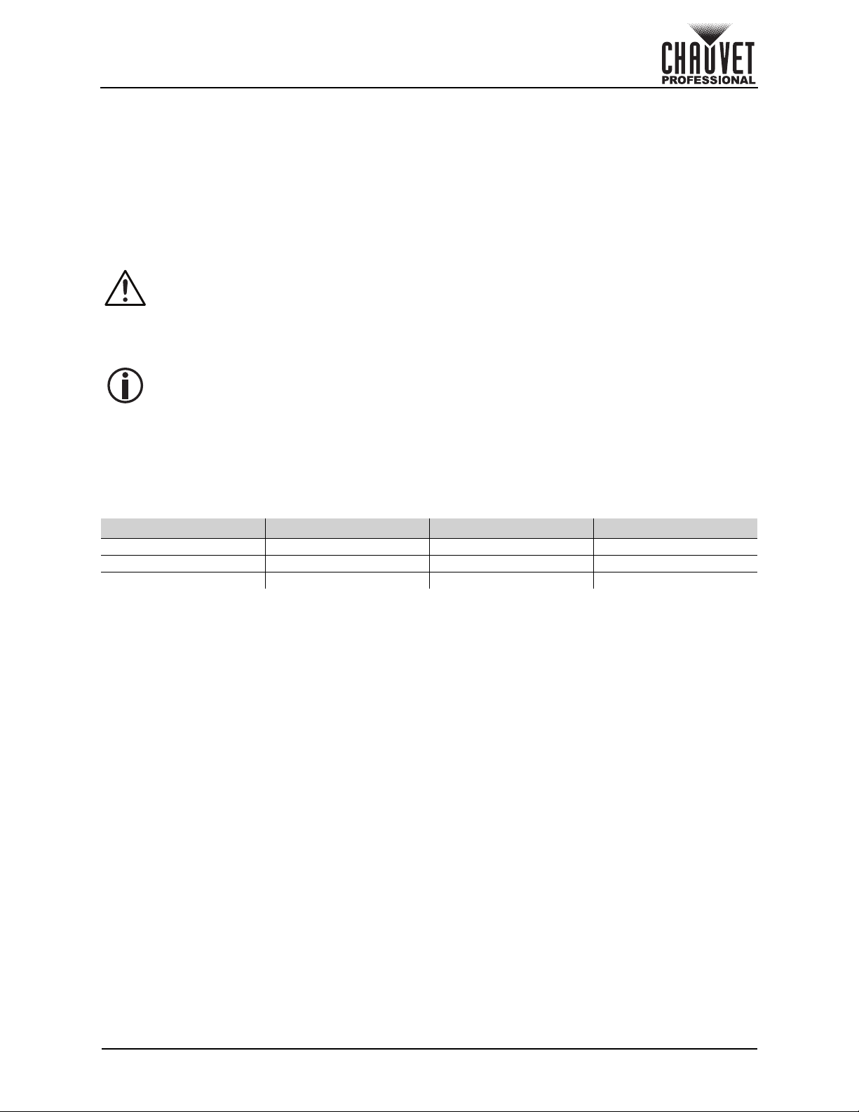
Gobo Wheels
1
6
3
7
5
2
4
Gobo Wheel 1
Rotating Gobo Wheel
Gobo Wheel 2
Static Gobo Wheel
IMAGE
32 mm
28 mm
Gobo Wheel Gobo # Description Gobo Wheel Gobo # Description
1
Operation
1 Sail Boats
2 Radial Dot 2 Bars
3 Mower Blade 3 Circles
4 Bolts 4 Breakup
5 Shower Glass 5 Dots
6 Ballistic Glass 6 Circuits
7 Four Eyes 7 Triangles
2
1 Beam
8 Forest
9 Rainbows
Gobo Dimensions
Page 26 of 33
Maverick MK3 Profile User Manual Rev. 1
Page 31

Operation
Gobo Holder
Gobo
Retaining Ring
Locate Pull Back Remove
Gobo Replacement
The gobos in gobo wheel 1 and 2 are removable from their gobo holders. This operation is quite simple,
although it requires the technician to carefully follow the recommended procedure.
• Make sure to disconnect the product’s power cord before replacing a gobo.
• Always replace a gobo with a gobo of the same dimensions.
• When inserting a glass gobo, always make sure that the shiny side of the gobo (glass base)
faces the lamp. This provides a layer of protection against the high temperature from the
lamp.
Procedure
1. Turn the product off and disconnect it from the power outlet.
2. Open the head cover by loosening the screws on the top cover.
3. Separate the gobo holder away from the gobo wheel by pushing it toward the front of the moving
head (direction 1 in the diagram). Be careful not to push the gobo out of the gobo holder.
4. Extract the gobo holder by pulling it outward (direction 2 in the diagram).
5. On a flat surface, remove the expansion ring that holds the gobo in place and remove the gobo
from the gobo holder.
6. Insert a new gobo and hold it in place with the expansion ring.
7. Slide the tip of the gobo holder under the pressure plate near the center of the gobo wheel.
8. Push the gobo holder inwards. DO NOT force the gobo holder into the gobo wheel slot. If correctly
installed, the gobo holder should easily slide into the gobo wheel slot.
Diagram
Maverick MK3 Profile User Manual Rev. 1
Page 27 of 33
Page 32

Maintenance
5. Maintenance
Product Maintenance
Dust build-up reduces light output performance and can cause overheating. This can lead to reduction of
the light source’s life and/or mechanical wear. To maintain optimum performance and minimize wear, clean
your lighting products at least twice a month. However, be aware that usage and environmental conditions
could be contributing factors to increase the cleaning frequency.
To clean the product, follow the instructions below:
1. Unplug the product from power.
2. Wait until the product is at room temperature.
3. Use a vacuum (or dry compressed air) and a soft brush to remove dust collected on the external
surface/vents.
4. Clean all transparent surfaces with a mild soap solution, ammonia-free glass cleaner, or isopropyl
alcohol.
5. Apply the solution directly to a soft, lint free cotton cloth or a lens cleaning tissue.
6. Softly drag any dirt or grime to the outside of the transparent surface.
7. Gently polish the transparent surfaces until they are free of haze and lint.
Always dry the transparent surfaces carefully after cleaning them.
Do not spin the cooling fans with compressed air. Damage may result.
Page 28 of 33
Maverick MK3 Profile User Manual Rev. 1
Page 33

Technical Specifications
UL 1573
CSA C22.2 No. 166
E113093
R
6. Technical Specifications
Dimensions and Weight
Length Width Height Weight
16.10 in (409 mm) 12.20 in (310 mm) 29.43 in (748 mm) 76.4 lb (34.7 kg)
Note: Dimensions in inches are rounded.
Power
Power Supply Type Range Voltage Selection
Switching (internal) 100 to 240 VAC, 50/60 Hz Auto-ranging
Parameter 120 V, 60 Hz 208 V, 60 Hz 230 V, 50 Hz
Consumption 1,070 W 1,050W 1,050 W
Operating Current 9.04 A 5.13 A 4.56 A
Fuse/Breaker F 20 A, 250 V F 20 A, 250 V F 20 A, 250 V
Power I/O U.S./Worldwide UK/Europe
Power Input Connector Seetronic Powerkon A Seetronic Powerkon A
Power Cord plug Edison (U.S.) Local Plug
Light Source
Type Color Quantity Power Current Lifespan
LED Cool white 1 820 W 24 A 30,000 hours
Photometrics
Beam Angle Field Angle Zoom Angle
6° to 45° 6° to 55° 6° to 55°
Illuminance @ 5 m (6°)
(without CRI filter)
Illuminance @ 5 m (55°)
(without CRI filter)
Illuminance @ 5 m (6°)
(with CRI filter)
Illuminance @ 5 m (55°)
(with CRI filter)
58,869 lux 1,860 lux 38,926 lux 1,222 lux
Thermal
Maximum External Temperature Cooling System
113 °F (45 °C) Fan-assisted Convection
DMX
I/O Connector Channel Range
3 and 5-pin XLR 38 or 54
Art-Net™/sACN
I/O Connector Channel Range
Amphenol XLR Net RJ45 in/out 38 or 54
Ordering
Product Name Item Name Item Code UPC Number
Maverick MK3 Profile
MAVERICKMK3PROFILE
08011553 781462219017
Maverick MK3 Profile User Manual Rev. 1
Page 29 of 33
Page 34

Technical Specifications
Beam FieldField
Beam FieldField
Maverick MK3 Profile Photometrics Charts
Narrow, Without CRI Filter Imperial Wide, Without CRI Filter
Beam
Distance
15 ft 1.57 ft 1.57 ft 6,541 207 12.43 ft 15.62 ft
20 ft 2.10 ft 2.10 ft 3,679 116 16.57 ft 20.82 ft
30 ft 3.14 ft 3.14 ft 1,635 52 24.85 ft 31.23 ft
40 ft 4.19 ft 4.19 ft 920 29 33.14 ft 41.65 ft
50 ft 5.24 ft 5.24 ft 589 19 41.42 ft 52.06 ft
75 ft 7.86 ft 7.86 ft 262 8 62.13 ft 78.09 ft
100 ft 10.48 ft 10.48 ft 147 5 82.84 ft 104.11 ft
125 ft 13.10 ft 13.10 ft 94 3 103.55 ft 130.14 ft
Diameter
Field
Diameter Footcandle Footcandle
Beam
Diameter
Field
Diameter
150 ft 15.72 ft 15.72 ft 65 2 124.26 156.17
Narrow, Without CRI Filter Metric Wide, Without CRI Filter
Beam
Distance
1 m 0.10 m 0.10 m 1,471,725 46,500 0.83 m 1.04 m
2 m 0.21 m 0.21 m 367,931 11,625 1.66 m 2.08 m
5 m 0.52 m 0.52 m 58,869 1,860 4.14 m 5.21 m
8 m 0.84 m 0.84 m 22,996 727 6.63 m 8.33 m
10 m 1.05 m 1.05 m 14,717 465 8.28 m 10.41 m
15 m 1.57 m 1.57 m 6,541 207 12.43 m 15.62 m
20 m 2.10 m 2.10 m 3,679 116 16.57 m 20.82 m
Diameter
Field
Diameter Lux Lux
Beam
Diameter
Field
Diameter
25 m 2.62 m 2.62 m 2,355 74 20.71 m 26.03 m
30 m 3.14 m 3.14 m 1,635 52 24.85 m 31.23 m
Page 30 of 33
Maverick MK3 Profile User Manual Rev. 1
Page 35

Technical Specifications
Beam FieldField
Beam FieldField
Narrow, With CRI Filter Imperial Wide, With CRI Filter
Beam
Distance
15 ft 1.57 ft 1.57 ft 4,325 136 12.43 ft 15.62 ft
20 ft 2.10 ft 2.10 ft 2,433 76 16.57 ft 20.82 ft
30 ft 3.14 ft 3.14 ft 1,081 34 24.85 ft 31.23 ft
40 ft 4.19 ft 4.19 ft 608 19 33.14 ft 41.65 ft
50 ft 5.24 ft 5.24 ft 389 12 41.42 ft 52.06 ft
75 ft 7.86 ft 7.86 ft 173 5 62.13 ft 78.09 ft
100 ft 10.48 ft 10.48 ft 97 3 82.84 ft 104.11 ft
125 ft 13.10 ft 13.10 ft 62 2 103.55 ft 130.14 ft
150 ft 15.72 ft 15.72 ft 43 1 124.26 156.17
Diameter
Field
Diameter Footcandle Footcandle
Beam
Diameter
Field
Diameter
Narrow, With CRI Filter Metric Wide, With CRI Filter
Beam
Distance
1 m 0.10 m 0.10 m 973,150 30,550 0.83 m 1.04 m
2 m 0.21 m 0.21 m 243,288 7,638 1.66 m 2.08 m
5 m 0.52 m 0.52 m 38,926 1,222 4.14 m 5.21 m
8 m 0.84 m 0.84 m 15,205 477 6.63 m 8.33 m
10 m 1.05 m 1.05 m 9,732 306 8.28 m 10.41 m
15 m 1.57 m 1.57 m 4,325 136 12.43 m 15.62 m
20 m 2.10 m 2.10 m 2,433 76 16.57 m 20.82 m
25 m 2.62 m 2.62 m 1,557 49 20.71 m 26.03 m
30 m 3.14 m 3.14 m 1,081 34 24.85 m 31.23 m
Diameter
Field
Diameter Lux Lux
Beam
Diameter
Field
Diameter
Maverick MK3 Profile User Manual Rev. 1
Page 31 of 33
Page 36

Returns
Returns
Send the product prepaid, in the original box, and with the original packing and accessories. Chauvet will
not issue call tags.
Call Chauvet and request a Return Merchandise Authorization (RMA) number before shipping the product.
Be prepared to provide the model number, serial number, and a brief description of the cause(s) for the
return.
To submit a service request online, go to www.chauvetprofessional.com/service-request
Clearly label the package with an RMA number. Chauvet will refuse any product returned without an RMA
number.
Write the RMA number on a properly affixed label. DO NOT write the RMA number directly
on the box.
Before sending the product, clearly write the following information on a piece of paper and place it inside
the box:
• Your name
• Your address
• Your phone number
•RMA number
• A brief description of the problem
Be sure to pack the product properly. Any shipping damage resulting from inadequate packaging will be
your responsibility. FedEx packing or double-boxing are recommended.
Chauvet reserves the right to use its own discretion to repair or replace returned
product(s).
.
Page 32 of 33
Maverick MK3 Profile User Manual Rev. 1
Page 37

Contact Us
Contact Us
Chauvet World Headquarters
Chauvet Europe Ltd
Chauvet Europe BVBA
Chauvet France
Chauvet Germany
Chauvet Mexico
Address: Av. de las Partidas 34 - 3B
Lerma, Edo. de México, CP 52000
General Information Technical Support
Address: 5200 NW 108th Ave. Voice: (844) 393-7575
Sunrise, FL 33351 Fax: (954) 756-8015
Voice: (954) 577-4455 Email: chauvetcs@chauvetlighting.com
Fax: (954) 929-5560
Toll Free: (800) 762-1084 Website: www.chauvetprofessional.com
Address: Unit 1C Email: UKtech@chauvetlighting.eu
Brookhill Road Industrial Estate
Pinxton, Nottingham, UK Website: www.chauvetprofessional.eu
NG16 6NT
Voice: +44 (0) 1773 511115
Fax: + 44 (0) 1773 511110
Address: Stokstraat 18 Email: BNLtech@chauvetlighting.eu
9770 Kruishoutem
Belgium Website: www.chauvetprofessional.eu
Voice: +32 9 388 93 97
Address: 3, Rue Ampère
91380 Chilly-Mazarin
France Website: www.chauvetprofessional.eu
Voice: +33 1 78 85 33 59
Address: Bruno-Bürgel-Str. 11
28759 Bremen
Germany Website: www.chauvetprofessional.eu
Voice: +49 421 62 60 20
(Entrance by Calle 2)
Zona Industrial Lerma Website: www.chauvetprofessional.mx
Voice: +52 (728) 690-2010
Email: FRtech@chauvetlighting.fr
Email: DEtech@chauvetlighting.de
Email: servicio@chauvet.com.mx
Visit the applicable website above to verify our contact information and instructions to request support.
Outside the U.S., U.K., Ireland, Benelux, France, Germany, or Mexico, contact the dealer of record.
Maverick MK3 Profile User Manual Rev. 1
Page 33 of 33
 Loading...