

Page 1
User Manual
Firmware V1.3
Page 2

Edition
Notes
The ÉPIX Drive 900 User Manual Rev. 4 c overs the desc ription, s afet y precau tions, ins tal lation,
released this edition
Trademarks
CHAUVET, the Chauv et logo and ÉPIX Drive 900 ar e registered trademark s or trademarks of
Chauvet & Sons Inc. (d/b/a Chauvet and Chauvet Lighting) in the United States and other
their respective companies.
Copyright Notice
The works of authorship contained in this manual, including, but not limited to, all design, text and
Electronically published by Chauvet in the United States of America.
Manual Use
Chauvet authorizes it s c us tomers to download and pri nt th is manual for professional inf or mation
purposes only. Chauv et expressly pr ohibits the usa ge, copy, storage, distribution , modification,
content for any other purpose without written consent from
Chauvet.
Document
Printing
For better results, pr int this docum ent in c olor, on lett er size pap er (8.5 x 11 i n), d ouble-sided. If
Intended
Any person in charge of ins talling, operatin g, and/or m aintaining this product s hould com pletely
read through the guide tha t shipped with the product, as well as this manual, before install ing,
operating, or maintaining this product.
Disclaimer
Chauvet believes that the information contained in this manual is accurate in all respects.
commit to make, any such revisions.
Document
The ÉPIX Drive 900 User Manual Rev. 4 supersedes all previous versions of this manual. Discard
any older versions of this manual and replace with this version. Go to
www.chauvetprofessional.com for the latest version.
Edition Notes
programming, operat ion, and maintenance of the ÉPIX Drive 900. Chauvet
of the ÉPIX Drive 900 User Manual in 2018.
countries. Other company and product names and logos referred to herein may be trademarks of
images are owned by Chauvet.
© Copyright 2018 Chauvet & Sons, Inc. All rights reserved.
or printing of this manual or its
using A4 paper (210 x 297 mm), configure your printer to scale the content accordingly.
Audience
However, Chauvet assumes no responsibility and specifically disclaims any and all liability to any
party for any loss, dam age or disruption caused by any errors or om issions in this document,
whether such errors or om issions result f rom negligen ce, ac cident or an y other c ause. Ch auvet
reserves the right to revise the content of this docum ent without any obligation to notify any
person or company of such revision, however, Chauvet has no obligation to make, and does not
Revision
ÉPIX Drive 900 User Manual Rev. 4
Page 3

Table of Contents
Table of Contents
1. Before You Begin ................................................................................................................................................... 1
What Is Included ....................................................................................................................................................................1
Claims .................................................................................................................................................................................................... 1
Manual Conventions .............................................................................................................................................................................. 1
Symbols ................................................................................................................................................................................................. 1
Product At A Glance ..............................................................................................................................................................2
Safety Notes ..........................................................................................................................................................................2
Personal Safety...................................................................................................................................................................................... 2
Mounting And Riggi ng ............................................................................................................................................................................ 2
Power And Wiring .................................................................................................................................................................................. 2
Operation ............................................................................................................................................................................................... 2
Expected LED Lifespan .........................................................................................................................................................2
2. Introduction ............................................................................................................................................................ 3
Description .............................................................................................................................................................................3
Features .................................................................................................................................................................................3
Overview ................................................................................................................................................................................3
Dimensions ............................................................................................................................................................................4
3. Setup ....................................................................................................................................................................... 5
AC Power ...............................................................................................................................................................................5
AC Plug.................................................................................................................................................................................................. 5
Power Linking ........................................................................................................................................................................5
Fuse Replacement ................................................................................................................................................................................. 5
Mounting ................................................................................................................................................................................6
Orientation ............................................................................................................................................................................................. 6
Rigging................................................................................................................................................................................................... 6
Procedure .............................................................................................................................................................................................. 6
Signal Connections ................................................................................................................................................................7
Art-Net™ Connection ............................................................................................................................................................................. 7
sACN Connection .................................................................................................................................................................................. 7
Kling-Net Connection ............................................................................................................................................................................. 7
Connecting ÉPIX Products ....................................................................................................................................................8
Connection Diagram .............................................................................................................................................................................. 9
4. Operation .............................................................................................................................................................. 10
Control Panel Description ....................................................................................................................................................10
Menu Map ............................................................................................................................................................................10
Ethernet Configuration .........................................................................................................................................................11
Protocol................................................................................................................................................................................................ 11
Start Universe ...................................................................................................................................................................................... 11
IP Addresses ....................................................................................................................................................................................... 11
Auto Addressing ...................................................................................................................................................................11
View Linked Fixtures ............................................................................................................................................................................ 11
Home Screen .......................................................................................................................................................................12
Display Orientation ...............................................................................................................................................................12
Device ID .............................................................................................................................................................................12
LED Output Test ..................................................................................................................................................................12
Factory Reset .......................................................................................................................................................................12
5. Firmware Update .................................................................................................................................................. 13
Instructions ...........................................................................................................................................................................13
Force Upload Instructions .................................................................................................................................................................... 14
6. Technical Information .......................................................................................................................................... 15
Product Maintenance ...........................................................................................................................................................15
7. Technical Specificat i ons ..................................................................................................................................... 16
Ordering ...............................................................................................................................................................................17
Returns ...................................................................................................................................................................... 18
Contact Us ................................................................................................................................................................ 19
ÉPIX Drive 900 User Manual Rev. 4 -i-
Page 4

Page 5
1. BEFORE YOU BEGIN
What Is
• ÉPIX Drive 900
• Rack ears (2) w/ screws
• Rubber feet (4)
• Quick Reference Guide
Claims
Carefully unpack the product immediately and check the box to make sure all the parts are in the
If the box or the contents (the product and included accessories) appear damaged from shipping
. Failure to report
tion, keep the box and
For other issues, such as missing components or parts, damage not related to shipping, or
concealed damage, file a claim with Chauvet within 7 days of delivery.
Manual
Convention
Meaning
1–512
A range of values in the text
50/60
A set of mutually exclusive values in the text
<SET>
A button on the product’s control panel
Settings
A product function or a menu option
MENU>Settings
A sequence of menu options
1–10
A range of menu values from which to choose in a menu
Yes/No
A set of two mutually exclusive menu options in a menu
ON
A unique value to be entered or selected in a menu
Symbols
Symbols
Meaning
Critical installation, configuration, or operation information. Failure to
damage third-party equipment, or cause harm to the operator.
The term “DMX” used throughout this manual refers to the USITT DMX512-A digital data
transmission protocol.
Before You Begin
Included
Conventions
• Neutrik® powerCON® power cord
• Warranty Card
package and are in good condition.
or show signs of mishandling, notify the carrier immediately, not Chauvet
damage to the carrier immediately may invalidate your claim. In addi
contents for inspection.
comply with this information may cause the product not to work,
Important installation or configuration information. Failure to comply
with this information may keep the product from working.
Useful information.
ÉPIX Drive 900 User Manual Rev. 4 -1-
Page 6
Product At A
x
P
x
P
x
P
P
x
Safety Notes
Read all the following Safety Notes before working with this product. These notes include
important information about the installation, usage, and maintenance of this product.
This product contains no user-serviceable parts. Any referen ce to serv icing in thi s User
housing or attempt any repairs.
Personal Safety
• Avoid direct eye exposure to the light source while the product is on.
• Do not touch this product’s housing during operation because it may be very hot.
Mounting And
• This product is for indoor use only! To prevent risk of fire or shock, do not expose this
• When hanging this product, always secure to a fastening device using a safety cable.
Power And
• Always make sure you are connecting this product to the proper voltage in accordance
• Never disconnect this product by pulling or tugging on the power cable.
Operation
• Do not operate this product if you see damage on the housing, lenses, or cables. Have the
• In case of a serious operating problem, stop using this product immediately!
Expected LED
LEDs gradually decline in brightness over time, due to heat. Packaged in clusters, LEDs exhibit
For this reason, using
intensity may help to extend the LEDs’ lifespan.
Before You Begin
Use on Dimmer
Glance
Rigging
Outdoor Use
Master/Slave
DMX
Manual will only apply to properly trained Chauvet certified technicians. Do not open the
All applicable local codes and regulations apply to proper installation of this product.
• Always disconnect this product from its power source before servicing.
• Always connect this product to a grounded circuit to avoid the risk of electrocution.
product to rain or moisture. (IP20)
• CAUTION: When transferring product from extreme temperature environments, (e.g. cold
truck to warm humid ballroom) condensation may form on the internal electronics of the
product. To avoid causing a failure, allow product to fully acclimate to the surrounding
environment before connecting it to power.
• Mount this product in a location with adequate ventilation, at least 20 in (50 cm) from
adjacent surfaces.
• Make sure there are no flammable materials close to this product while it is operating.
Auto Programs
Auto-Ranging Power Supply
Replaceable Fuse
User-Serviceable
Wiring
Lifespan
with the specifications in this manual or on the product’s specification label.
• To eliminate unnecessary wear and improve its lifespan, during periods of non-use
completely disconnect the product from power via breaker or by unplugging it.
• Never connect this product to a dimmer pack or rheostat.
damaged parts replaced by an authorized technician at once.
• Do not cover the ventilation slots when operating to avoid internal overheating.
• The maximum ambient temperature is 113 °F (45 °C). Do not operate this product at a
higher temperature.
If your Chauvet product requires service, contact Chauvet Technical Support.
higher operating temperatures than in ideal, single-LED conditions.
clustered LEDs at their fullest intensit y significantly reduces the LEDs’ lifespan. Under normal
conditions, this lif espan c an be 4 0,000 to 5 0,000 hour s. If extending th is lif espan is vita l, lower
the operating temperature by improving the ventilation around the product and reducing the
ambient temperature to an optimal operating r ange. In addition, lim iting the overall projec tion
-2- ÉPIX Drive 900 User Manual Rev. 4
Page 7
2. INTRODUCTION
Description
ÉPIX Drive 900 hosts the pr ocessing and power supply for the ÉPIX T our product line in one
based remote web server.
Features
• Ethernet, processing, and power hub for ÉPIX Tour product line.
• Neutrik® powerCON® power input/output connections
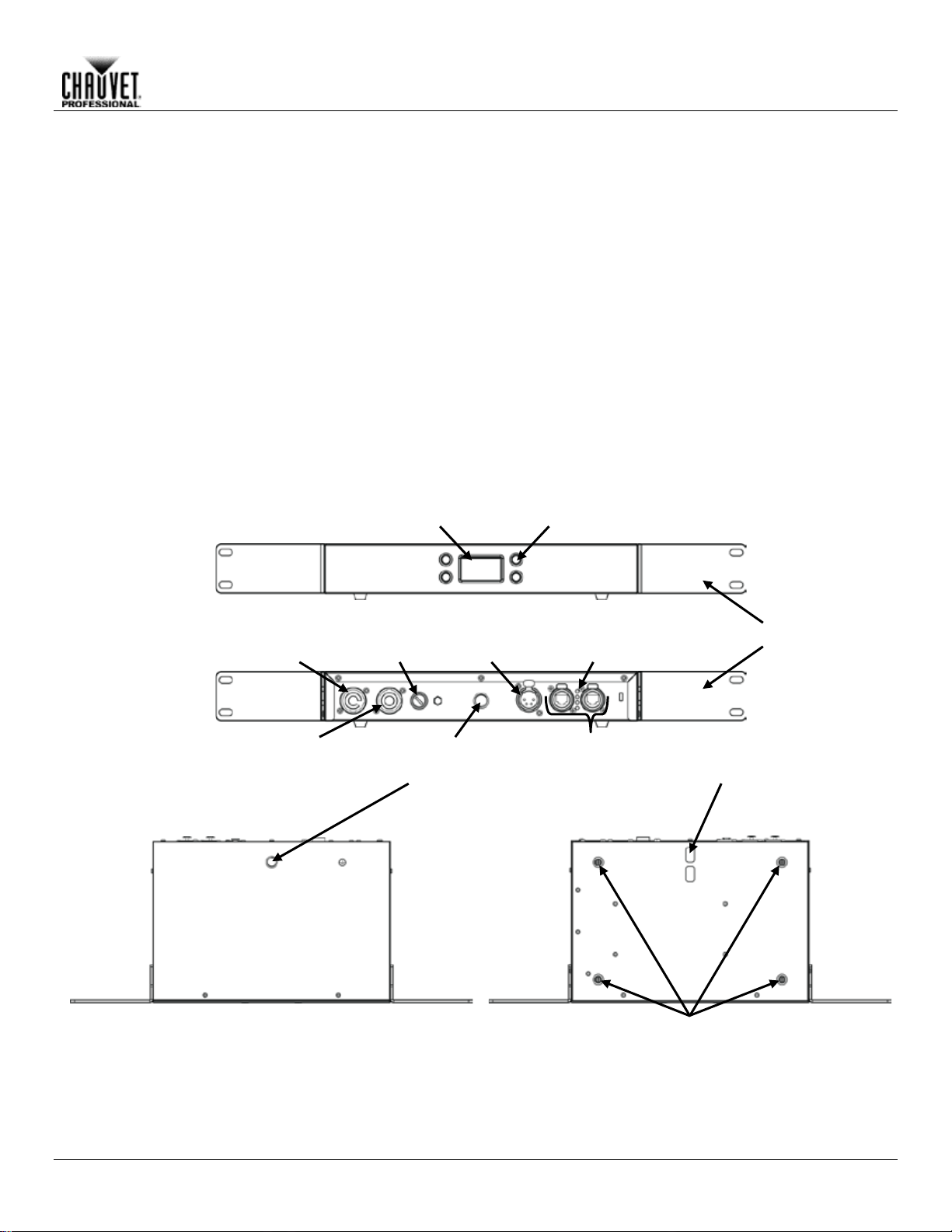
Front View
Top View
Rear View
Signal In/Out
(Through)
Fuse
Holder
Neutrik®
powerCON® In
Neutrik®
powerCON® Out
M12
Mounting
Points
ÉPIX Product
(4-pin XLR)
OLED
Display
Menu
Buttons
Rubber
Feet
Removable Rack Ears
Indicator
LEDs
Bottom View
convenient device. It controls up to 18 ÉPIX Strip Tour, 36 ÉPIX Strip Tour 50, or 6 ÉPIX Bar Tour
products easily using Art-Net™, sACN, or ArKaos Kling-Net. Co nfiguration and s etup is fast and
easy with its bu ilt-in OLED display. Additi onally, configuration can be managed w ith a network-
• Operating modes:
o Art-Net™
o sACN
o ArKaos Kling-Net
• Auto-address function
• Single 4-pin XLR output
• 2700 Art-Net™ channels
• Steel housing
Overview
Introduction
Output
Safety Cable
Pass-Through
ÉPIX Drive 900 User Manual Rev. 4 -3-
Page 8

7.6 in
193 mm
19.02 in
483 mm
18.31 in
465 mm
1.18 in
1.7 in
1.97 in
1.7 in
11.14 in
283 mm
Introduction
Dimensions
44 mm
50 mm
30 mm
44 mm
-4- ÉPIX Drive 900 User Manual Rev. 4
Page 9

3. SETUP
AC Power
Each ÉPIX Drive 900 has an auto-ranging power suppl y that works with an input voltage rang e
,
chart
The listed current r ati ng in d icat es t he maximum current dr a w dur i ng normal operation. For more
:
www.chauvetprofessional.com.
• Always connect this product to a protected circuit with an appropriate electrical
completely disconnect the product from power via breaker or by unplugging it.
Never connect this product to a rheostat (variable resistor) or dimmer circuit, even if the rheostat
or dimmer channel serves only as a 0 to 100% switch.
AC Plug
The ÉPIX Drive 900 comes with a pow er input cord term inated with a Neutrik ® powerCON® A
connector on one end and an Edison plug on the other end (U.S. market). If the power input cord
table
below to wire the new plug.
Connection
Wire (U.S.)
Wire (Europe)
Screw Color
AC Live
Black
Brown
Yellow or Brass
AC Neutral
White
Blue
Silver
AC Ground
Green/Yellow
Green/Yellow
Green
Power Linking
The ÉPIX Drive 900 supports power linking. You can power link up to 6 products at
for
purchase.
Fuse
Disconnect this product from the power outlet.
Screw the fuse holder cap back in place and reconnect power.
Make sure to disconnect the product’s power cord before replacing a blown fuse. Always
replace the blown fuse with another of the sa me type an d ra ting.
Setup
of 100 to 240 VAC, 50/60 Hz. To det ermine the po wer requirements f or each ÉPIX Drive 900
refer to the label affixed to the pr oduct. You can also r efer to the T echnical Specif ications
in this manual.
information, you may download Sizing Circuit Breakers from the Chauvet website
ground to avoid the risk of electrocution or fire.
• To eliminate unnecessary wear and improve its lifespan, during periods of non-use
that came with your product has no plug, or if you need to change the Edison plug, use the
120 V; up to 11 at 208 V; or up to 12 at 230 V.
This product comes with a power input cord. Power linking cables are available from Chauvet
Replacement
Using a flat-head screwdriver, unscrew the fuse holder cap from the housing.
Remove the blown fuse and replace with another fuse of the same type and rating
(T 5 A, 250 V).
ÉPIX Drive 900 User Manual Rev. 4 -5-
Page 10

Mounting
Before mounting this product, read and follow the Safety Notes. For our CHAUVET
Professional line of mounting clamps, go to http://trusst.com/products/.
Orientation
Always mount this product in a safe position and make sure there is adequate room for ventilation,
configuration, and maintenance.
Rigging
Chauvet recommends using the following general guidelines when mounting this product.
from people and vehic les.
Procedure
The ÉPIX Drive 900 fits nicely in a standard 19” rack using the included removable rack ears. You
may also choose to attach a M12 m ounting clam p for hanging or simpl y place it on its f eet on a
ware and
Professional line of mounting clamps, go to http://trusst.com/products/.
Rack Mounting
Overhead Mounting
Surface Mounting
Removable Rack Ear (x2)
Screw (x4)
Rubber Feet (x4)
Mounting Clamp
(Only one needed)
Setup
• When selecting an installation location, consider easy access to this product for operation,
programming adjustments, and routine maintenance.
• The product is not intended for permanent installation.
• Make sure to mount this product away from any flammable material as indicated in the
Safety Notes.
• Never mount in places where rain, high humidity, extreme temperature changes, or
restricted ventilation may affect the product.
• Before deciding on a location, always make sure there is easy access to the product for
maintenance and programming.
• If hanging this product, make sure that the mounting location can support the product’s
weight. See the T echnic al Specif icat io ns for the weight-bearing requirements of this
product.
• When hanging this product, always secure to a fastening device using a safety cable. For
our CHAUVET Professional line of safety cables, go to http://trusst.com/products/.
• When mounting the product on the floor, make sure that the product and cables are away
flat level surfac e. You must suppl y your own mounting h ardware. Make sure a ll hard
mounting surfaces are capable of supporting the weight of this product. For our CHAUVET
Mounting Diagram
Safety Cable
-6- ÉPIX Drive 900 User Manual Rev. 4
Page 11

Setup
Signal Connections
You can link the ÉPIX Drive 900 to c ontroller software using an Eth ernet connection. If using
control each individually on a single network.
Art-Net™
Art-Net™ is an Ethern et protocol t hat uses T CP/IP which transfers a large amoun t of DMX512
Art-Net™ designed by and copyright Artistic Licence Holdings Ltd.
sACN
Also known as ANSI E1.3 1, Stream ing-ACN is an Ethernet pr otocol that us es the layering an d
ACN compatible network. ACN is maintained by the Professional Lighting and Sound
Association (PLASA).
Kling-Net
Kling-Net is a network protocol that allows auto configuration of display devices using a Neutrik®
etherCON® RJ45 Ethernet connection. Refer to the ArKaos software manual for detailed
instructions on programming this product.
For smooth-running operation, ArKaos Kl ing-Net requires a gi gabit (1000 Mbps) Ethe rnet
from CHAUVET Professional)
ÉPIX Drive 900
Net™,
Net™,
other Art-Net™, sACN or Kling-Net-compatible products with the ÉPIX Drive 900, you can
Connection
Connection
data using an Neutrik® etherCON® RJ45 connection over a large network. An Art-Net™ protocol
document is available from www.chauvetprofessional.com.
formatting of Architectur e for Control Net works to tr ansport DMX512 data over IP or any other
Connection
card and network router.
Connection
Diagram
Computer/Controller
(running Kling-Net, Art-
or sACN protocol)
Switch or Router
(such as the NET-Switch
To other Kling-Net, Art-
or sACN Devices
Never connect an ÉPIX product to the WAN port of a router.
ÉPIX Drive 900 User Manual Rev. 4 -7-
Page 12

Connecting
The ÉPIX Drive 900 uses a 4-pin XLR connection to link all ÉPIX Tour products. Each ÉPIX
product connected to one ÉPIX Drive 900.
Strip Tour
Strip Tour 50
Bar Tour
Strip Tour
Strip Tour 50
Bar Tour
18 0 0 5 26 0 17 2 0 5 20 1 16 4 0 5 14 2 15 6 0 5 8 3 15 0 1 5 2 4 14 8 0 4 28 0 14 2 1 4 22 1 13
10 0 4
16 2 13 4 1 4 10 3 12
12 0 4 4 4
12 6 1 3 30 0 12 0 2 3 24
18
11
14 0 3
18 2 11 8 1 3 12 3 11 2 2 3 6 4 10
16 0 3 0 5
10
10 1 2
32 0 10 4 2 2 26 1 9
18 0 2
20 2 9
12 1 2
14 3 9 6 2 2 8 4 9 0 3 2 2 5 8
20 0 1
34 0 8
14 1 1
28 1 8 8 2 1 22 2 8 2 3 1 16 3 7
22 0 1
10 4 7
16 1 1 4 5 7 10 2 0
36 0 7 4 3 0 30 1 6
24 0 0
24 2 6
18 1 0
18 3 6
12 2 0
12 4 6 6 3 0 6 5 6 0 4 0 0
6
Setup
ÉPIX Products
Tour product must be daisy-chained together in series. Each ÉPIX Drive 900 can support up to
900 LEDs in 70 possible configurations that max out the capability of the product. The table
below gives the maximum number of each product for the maximum given of each other
-8- ÉPIX Drive 900 User Manual Rev. 4
Page 13

Connection Diagram
• The ÉPIX Drive 900 can support up to 18 ÉPIX Strip Tour products, 6 ÉPIX Bar Tour
cable length to 300 feet (91 meters).
Length of cables between products must
not exceed 60 ft (18 m) when shielded,
or 100 ft (30 m) when unshielded
Length of cables between ÉPIX Drive 900 and 1st product must not
exceed 65 ft (20 m) when shielded, or 150 ft (45 m) when unshielded
Total length of cables cannot exceed 210 ft (64 m) when shielded,
4-pin XLR Cable Diagram
1 = Power +
2 = Data +
3 = Data
4 = Power
(16 AWG or larger)
(18
(18
(16 AWG or larger)
Setup
or 300 ft (91 m) when unshielded
–24 AWG)
-
-
–24 AWG)
products, or 36 ÉPIX Strip Tour 50 products, or any combination up to 900 LEDs.
• Make sure the total length of the connecti ng shielded 4-pin XLR cables does not
exceed 210 feet (64 meters). Using unshielded cables will increase the maximum
Most standard 4-pin XLR “Scroller” cables are shielded .
ÉPIX Drive 900 User Manual Rev. 4 -9-
Page 14

Control Panel
Button
Function
Exits from the current menu or function or cycles through the main level
of the menu
Navigates upward through the menu list or increases the numeric value
when in a function
Navigates downward through the menu list or decreases the numeric
value when in a function
Enables the currently displayed menu or sets the currently selected
value in to the current function
Menu Map
Main Level
Programming Levels
Description
Art-Net
Kling-Net
sACN
Yes
No
Yes
No
0–250
(Art-Net™)
1-250
(sACN)
IP Address #1 to
(Art-Net™ or sACN only)
Device ID
xxxxxxxxxx
Shows device ID
View Linked Fixture
1. X** – 36. X**
Shows the connected products in order
Off
Turn off all LED output
Red
Red LEDs at full
Green
Green LEDs at full
Blue
Blue LEDs at full
White
White LEDs at full
Fade
Color roll fade at full
Scroll
Rainbow roll at full
Yes
No
* - In Art-Net™ mode, the beginnings of the IP addresses can be set to 2 or 10, and
** - The display will show either ÉPIX Strip tour, ÉPIX Bar Tour, or nothing.
Firmware V1.3
Operation
4. OPERATION
Description
<MENU/ESC>
<UP>
<DOWN>
<ENTER>
Protocol
Auto Address
Display Inverse
Start Universe
(Art-Net™ or sACN only)
Selects the Ethernet protocol and determines
what other Menu options are available
Automatically find and address the products
Turn display 180 degrees
Sets the lowest of the 6 consecutive Art-Net™
or sACN universes the product is assigned to
IP Address #6
LED Output
Factory Reset
-10- ÉPIX Drive 900 User Manual Rev. 4
in sACN mode they can also be set to 239.
x*.xxx.xxx.xxx
Sets the IP addresses for the ÉPIX Drive 900
Note: The addresses cannot be the same
Resets products to factory defaults
Page 15

Operation
Ethernet
The ÉPIX Drive 900 opera tes by routing one of t hree Ethernet protocols (Art-Net™, sACN, or
must
for more
information on menu options.
Protocol
To configure the protocol for the ÉPIX Drive 900, follow the instructions below:
Press <ENTER>.
Start Universe
Each ÉPIX Drive 9 00 uses 6 consecutiv e universes in Art-Net™ mode and sACN mode, whic h
Press <ENTER>.
Each universe can support up to 3 ÉPIX Strip Tour products or 1 ÉPIX Bar Tour product.
grouped together, 3 to a universe.
IP Addresses
In Art-Net™ and s ACN mode, the ÉPIX Drive 900 d edicates a separate IP address f or each
Repeat steps 3-4 until the IP address is set as desired.
• The beginnings of the IP addresses can be set to 2 or 10 in Art-Net™ mode. In sACN
• The IP addresses cannot be identical.
Auto
The ÉPIX Drive 900 addre sses c onnected pro ducts with the A uto Addres s funct ion. To p erform
Press <ENTER>.
Perform an Auto Address every time products are connected, disconnected, or
reconfigured, as soon as all changes have been made.
Each LED in each ÉPIX product requires 3 control channels. F or each type of ÉPIX
When multiple types of ÉPIX products are used, products will be addressed in order of
connection.
View Linked
To view all of the fixtur es discovered by the Auto Addressing f unction, follow the instructions
Use <UP> or <DOWN> to scroll through the list of dis c overed prod ucts , 1–36.
Configuration
Kling-Net) to the ÉPIX Tour products linked to the output of the Drive. The Ethernet protocol
be set for the products to respond correctly to the controller. See the Menu Map
Press <MENU> repeat ed ly until Protoc o l shows on the dis pl a y.
Press <ENTER>.
Use <UP> or <DOWN> to select Art-Net, Kling-Net, or sACN.
are assigned by setting the starting (lowest-numbered) universe address.
To set the address of the starting universe, do the following:
Press <MENU> repeat ed ly until Start Universe shows on the display.
Press <ENTER>.
Use <UP> or <DOWN> to select a starting universe address, 0–250 (for Art-Net™),
or 1–250 (for sACN).
Regardless of the order in which they are connected, ÉPIX S trip Tour products will be
universe. To set any of the 6 IP addresses in the ÉPIX Drive 900, follow the instructions below:
Press <MENU> repeatedly until IP Address #X shows on the display.
Press <ENTER>.
Use <UP>or <DOWN> to set the highlighted number.
Press <ENTER>.
mode, they can also be set to 239. The beginnings of each IP address will always
match.
Addressing
Fixtures
ÉPIX Drive 900 User Manual Rev. 4 -11-
an Auto Address, do the following:
Press <MENU> repeatedly until Auto Address shows on the display.
Press <ENTER>.
Use <UP> or <DOWN> to select Yes.
product, channel assignments will be as follows:
• ÉPIX Strip Tour (150 channels each): 1, 151, 301, 451 (4 per universe)
• ÉPIX Strip Tour 50 (75 channels each) : 1, 76, 151, 226, 301, 376, 451 (7 per universe)
• ÉPIX Bar Tour (450 channels each): 1 (1 per universe)
below:
Press <MENU> repeatedly until View Linked Fixture shows on the display.
Press <ENTER>.
Page 16

Home Screen
The ÉPIX Drive 900 has a home screen that displays the current protocol mode and
The home screen can also be viewed by pressing and ho lding <MENU> for 2 seconds.
Display
To re-orient the display for easier reading in different mounting applications, do the following:
Press <ENTER>.
Device ID
To view the Device ID of the ÉPIX Drive 900:
Press <ENTER>.
LED Output
Output Test mode allows t he user to test each output of the ÉPIX Drive 900, as well as the
Press <ENTER>.
The ÉPIX Drive 900 will remain in Output Test mode until it receives a signal from a
the color output without sending a signal to the product, set the LED
Output to Off.
Factory Reset
To reset the product to factory defaults:
Press <ENTER>.
Operation
IP addresses, or the Output Test mode. This screen shows at start-up, and after 15 seconds with
no menu activity.
Orientation
Test
Press <MENU> repeatedly until Display Inverse shows on the display.
Press <ENTER>.
Use <UP> or <DOWN> to select Yes (for inverted) or No (for normal).
Press <MENU> repeat ed ly until Device ID shows on the display.
functionality of their ÉPIX Tour products. To run an output test:
Press <MENU> re peat ed l y until LED Output shows on the display.
Press <ENTER>. The current test mode will begin to output.
Use <UP> and <DOWN> to select one of seven output test modes: Red, Green, Blue,
White, Fade, Scroll, or Off.
controller. To stop
Press <MENU> repeat ed ly until Factory Reset shows on the display.
Press <ENTER>.
Use <UP> or <DOWN> to select Yes.
After a Factory Reset, the ÉPIX Drive 900 will be set to A rt-Net™ mode.
-12- ÉPIX Drive 900 User Manual Rev. 4
Page 17

5. FIRMWARE UPDATE
On occasion, updates to t he firm ware for the ÉPIX Drive 900 are available . The following is the procedure f or obtaining
and installing these updates on a Windows PC.
Instructions
Download the CHAUVET Professional Uploader from
Click Next.
Click Find Compatible Devices.
Select the checkbox next to Epix Tour 900.
http://www.chauvetprofessional.com/products/epixdrive-900 and install it.
Download the latest firmware update from
http://www.chauvetprofessional.com/products/epixdrive-900.
• After downloading the software and update file, disable
or disconnect any networks the PC is connected to. Do
NOT disable the network created when the ÉPIX Drive
900 is connected in the next step.
Power on the ÉPIX Drive 900 and connect it to the
computer using an ethernet cable.
Open the ÉPIX Drive 900 upload software.
Use the Browse option to select the latest firmware
update to upload.
Technical Information
Click Next when the software indicates a device has
been found.
• If the software cannot find the ÉPIX Drive 900 on the
network, see Force Upload Instructions.
Click Upload Firmware.
Wait for the upload to complete. Do NOT disconnect or
power off the product during this process.
When the status field says Done, exit out of the upload
software.
Disc onnect the É PIX Drive 900 from the computer. The
firmware update is complete.
ÉPIX Drive 900 User Manual Rev. 4 -13-
Page 18

Force Upload Instructions
In the event that the upload software cannot find the ÉPIX Drive 900 on the network, follow the instructions below:
Turn off the ÉPIX Drive 900. Press and hold <MENU>
Click Upload Firmware.
Firmware Update
and <ENTER>, then turn it back on. The display menu
will flash, indicating the product is in Force Upload
mode.
After selecting the firmware update file and continuing
to the Find Compatible Devices page, check off the
Force Upload option.
Click Next.
Wait for the upload to complete. Do NOT disconnect or
power off the product during this process.
When the upload is complete, exit out of the upload
software.
Disconnect the ÉPIX Drive 900 from the computer. The
firmware update is complete.
-14- ÉPIX Drive 900 User Manual Rev. 4
Page 19

6. TECHNICAL INFORMATION
Product
To maintain optim um performance and m inimize wear, you should c lean this product f requently.
up reduces light output
Gently polish the lens surfaces until they are free of haze and lint.
Technical Information
Maintenance
Usage and environment are contributing factors in determining the cleaning frequency.
As a rule, clean this product at least twice a month. Dust buildperformance and can cause overheating. This can lead to reduced light source life and increased
mechanical wear.
To clean your product:
Unplug the product from power.
Wait until the product is at room temperature.
Use a vacuum (or dry compressed air) and a soft brush to remove dust collected on the
external vents.
Clean all external surfaces with a mild solution of non-ammonia glass cleaner or isopropyl
alcohol.
Apply the solution directly to a soft, lint-free cotton cloth or a lens cleaning tissue.
Wipe any dirt or grime to the outside edges of the lens surface.
Always dry the external surfaces thoroughly and carefully after cleaning them.
Do not spin the cooling fans by blowing compressed air into them.
ÉPIX Drive 900 User Manual Rev. 4 -15-
Page 20

Dimensions and
Length
Width
Height
Weight
19 in (483 mm)
7.6 in (193 mm)
2 in (50 mm)
5.4 lb (2.5 kg)
Note: Dimensions in inches rounded to the nearest decimal digit.
Power
Power Supply Type
Range
Voltage Selection
Switching (internal)
100–240 VAC, 50/60 Hz
Auto-ranging
Parameter
120 VAC, 60 Hz
208 VAC, 60 Hz
230 VAC, 50 Hz
Consumption
299 W
299 W
299 W
Current
2.53 A
1.44 A
1.31 A
Power linking curren t (product s)
13.6 A (6 products)
13.6 A (11 products)
13.6 A (12 products)
Fuse/Breaker
T 5 A, 250 V
T 5 A, 250 V
T 5 A, 250 V
Power I/O
U.S./Canada
Worldwide
Power input connector
Neutrik® powerCON® A
Neutrik® powerCON® A
Power output connector
Neutrik® powerCON® B
Neutrik® powerCON® B
Power cord plug
Edison (U.S.)
Local plug
ÉPIX Product Output
Output Connector
Output Voltage
4-pin XLR
48 VDC
ÉPIX Product
Maximum Load Per Drive
LEDs Per Product
ÉPIX Strip Tour
18 products
50
ÉPIX Strip Tour 50
36 products
25
ÉPIX Bar Tour
6 products
150
any combination up to 900 LEDs
Maximum Cable
Shielded
Unshielded
From Drive to 1st ÉPIX product
65 ft (20 m)
150 ft (45 m)
Between ÉPIX products
60 ft (18 m)
100 ft (30 m)
Total from Drive through all
ÉPIX products
Art-Net™ and sACN
I/O Connector
Channel Range
Amphenol XLRnet
2700
ArKaos Kling-Net
I/O Connector
Channel Range
Determined per ArKaos
MediaMaster software
Thermal
Max. External Temperature
Cooling System
113 °F (45 °C)
Fan-Assisted Convection
Technical Specifications
7. TECHNICAL SPECIFICATIONS
Weight
Lengths
Amphenol XLRnet
-16- ÉPIX Drive 900 User Manual Rev. 4
210 ft (64 m) 300 ft (91 m)
Page 21

Ordering
Product Name
Item Name
Item Code
UPC Number
ÉPIX Products
ÉPIX Drive 900
EPIXDRIVE900
03091141
781462214890
ÉPIX Strip Tour
EPIXSTRIPTOUR
03091139
781462214876
ÉPIX Strip Tour 50
EPIXSTRIPTOUR50
09031436
781462217846
ÉPIX Bar Tour
EPIXBARTOUR
03091140
781462214883
Accessories
ÉPIX Strip Tour Dome
Accessory (4 pieces)
4-pin XLR Cables
4-pin XLR Extension
Cable, 16 in
4-pin XLR Extension
Cable, 5 ft
4-pin XLR Extension
Cable, 50 ft
etherCON Cables
Neutrik® etherCON®
Extension Cable, 18 in
Neutrik® etherCON®
Extension Cable, 5 ft
Neutrik® etherCON®
Extension Cable, 10 ft
Neutrik® etherCON®
Extension Cable, 25 ft
Neutrik® etherCON®
Extension Cable, 50 ft
powerCON Cables
Neutrik® powerCON®
Extension Cable, 18 in
Neutrik® powerCON®
Extension Cable, 5 ft
Neutrik® powerCON®
Extension Cable, 10 ft
Neutrik® powerCON®
Extension Cable, 25 ft
Neutrik® powerCON®
Extension Cable, 50 ft
For the most current list of related products and accessories available from CHAUVET
Professional, visit our webs ite at www.chauvetprofessional.com.
Technical Specifications
EPIXSTRIPDOME 03091142 781462214906
4PINEXT16IN 19111143 781462214913
4PINEXT5FT 19111144 781462214920
4PINEXT50FT 19111147 781462214951
ETHERCONEXT18IN 19090363 781462207151
ETHERCONEXT5FT 19090364 781462207168
ETHERCONEXT10FT 19090365 781462207175
ETHERCONEXT25FT 19090366 781462207182
ETHERCONEXT50FT 19090367 781462207199
POWERCONEXT18IN 19110372 781462207243
POWERCONEXT5FT 19110373 781462207250
POWERCONEXT10FT 19110374 781462207267
POWERCONEXT25FT 19110375 781462207274
POWERCONEXT50FT 19110376 781462207281
ÉPIX Drive 900 User Manual Rev. 4 -17-
Page 22

R
To get support or return a product:
If you are located in an y other country, DO NOT contact Chauvet. Instead, cont act your local
, UK, Ireland,
Benelux, France, Germany, or Mexico.
If you are located outside the U.S., UK, Ireland, Benelux, France, Germany, or Mexico,
contact your distributor of record and follow their instructions on how to return Chauvet
products to them. Visit our website www.chauvetprofessional.com for c o ntact details.
Call the corresponding Chauvet Technical Support office and request a Return Merchandise
Authorization (RMA) number before shipping the product. Be prepared to provide the model
Send the merchandise pr epai d, in its or iginal b ox, an d with i ts orig inal pack ing a nd ac cess ories.
an RMA number.
Write the RMA number on a properly affixed label. DO NOT write the RMA number dire ctly
on the box.
Before sending the produc t , c learly write the following i nf ormation on a piece of paper and place
Be sure to pack the product properly. Any shipping damage resulting from inadequate packaging
will be your responsibility. FedEx packing or double-boxing are recommended.
Chauvet reserves the right to use its own discretion to repair or replace returned
product(s).
User Manual
ETURNS
• If you are located in the U.S., contact Chauvet World Headquarters.
• If you are located in the UK or Ireland, contact Chauvet Europe Ltd.
• If you are located in Benelux, contact Chauvet Europe BVBA.
• If you are located in France, contact Chauvet France.
• If you are located in Germany, contact Chauvet Germany.
• If you are located in Mexico, contact Chauvet Mexico.
distributor. See www.chauvetprofessional.com for distributors outside the U.S.
number, serial number, and a brief description of the cause for the return.
To submit a service request online, go to www.chauvetprofessional.com/service-request.
Chauvet will not issue call tags.
Clearly label the package with the RMA number. Chauvet will refuse any product returned without
it inside the box:
• Your name
• Your address
• Your phone number
• RMA number
• A brief description of the problem
-18- ÉPIX Drive 900 User Manual Rev. 4
Page 23

World Headquarters
Address: 5200 NW 108th Avenue
Toll free: (800) 762-1084
Voice: (844) 393-7575
Website www.chauvetprofessional.com
UK
Address: Unit 1C
Email: UKtech@chauvetlighting.eu
Benelux
Address: Stokstraat 18
Email: BNLtech@chauvetlighting.eu
France
Address: 3, Rue Ampère
Voice: +33 1 78 85 33 59
Email: FRtech@chauvetlighting.fr
Germany
Address: Bruno-Bürgel-Str. 11
Voice: +49 421 62 60 20
Email: DEtech@chauvetlighting.de
Mexico
Address: Av. de las Partidas 34-3B
Voice: +52 (728) 690-2010
Email: servicio@chauvet.com.mx
Outside the U.S., U.K., Ireland, Benelux, France, Germany, or Mexico, contact the dealer of
contact details
CONTACT
User Manual
General Information Technical Support
US
Sunrise, FL 33351
Voice: (954) 577-4455
Fax: (954) 929-5560
Brookhill Road Industrial Estate
Pinxton, Nottingham, UK
NG16 6NT
Voice: +44 (0)1773 511115
Fax: +44 (0)1773 511110
9770 Kruishoutem
Belgium
Voice: +32 9 388 93 97
91380 Chilly-Mazarin
France
Fax: (954) 756-8015
Email: chauvetcs@chauvetlighting.com
Website: www.chauvetprofessional.eu
Website: www.chauvetprofessional.eu
Website: www.chauvetprofessional.eu
28759 Bremen
Germany
Website: www.chauvetprofessional.eu
(Entrance by Calle 2)
Zona Industrial Lerm a
Website: www.chauvetprofessional.mx
Lerma, Mexico C.P. 52000
record. Follow the instructions to request support or to return a product. Visit our website for
ÉPIX Drive 900 User Manual Rev. 4
 Loading...