

Page 1

User Manual
Page 2

Edition
Notes
The WELL™ Flex User Manual Rev. 1 covers the des cription, safety precautions, instal lation,
Trademarks
CHAUVET® is a registered trademark of CHAUVET & Sons Inc. (d/b/a CHAUVET® or
. Any other
within this document are the property of their respective trademark holders.
Copyright Notice
Chauvet owns the content of this User Manual in its entirety, including but not limited to
Electronically published by Chauvet in the United States of America.
Manual Use
Chauvet authorizes it s c us tomers to download and print this manual for professional information
without written consent from
Chauvet.
Document
Printing
For better results, pr int this docum ent in c olor, on lett er size pap er (8.5 x 11 in) , doub le-sided. If
Intended
Any person in charge of ins talling, operating, an d/or m aintaining this product sh ould com pletely
operating, or maintaining this product.
Disclaimer
Chauvet believes that the information contained in this manual is accurate in all respects.
a revision of this manual or a new edition to incorporate such changes.
Document
Revision
The WELL™ Flex User Manual Rev. 1 is the first edition of this manual. Go to
Author
Date
Editor
Date
D. Couppe
2/5/15
A. Leon
2/6/15
Edition Notes
programming, operatio n, a nd maintenance of the W ELL™ Flex . Chauvet released this edit io n of
the WELL™ Flex User Man ual in February 2015.
Chauvet). The CHAUVET® log o in its entirety including the CHAUVET ® name and the dotted
triangle, and all other trade marks in this manual pertaining to s ervices, products, or marketing
statements (example: It’s Green Thinking™) are owned or licensed by Chauvet
product names, logos, bra nds, company names, and other trademark s featured or referred to
pictures, logos, trademarks, and resources.
© Copyright 2015 Chauvet. All rights reserved.
purposes only. Chauvet expressly proh ibits the usage , copy, storage, distribution, m odification,
or printing of this manual or its content for any other purpose
using A4 paper (210 x 297 mm), configure your printer to scale the content accordingly.
Audience
read through the guide tha t shipped with the product, as well as this manual, before installing,
However, Chauvet assumes no responsibility for any errors or omissions in this document.
Chauvet reser ves the r ight to revise a nd m ak e change s to the co nte nt of this doc um ent without
obligation that Chauvet n otify any person or compan y of such revision or changes. This does
not in any way constitute a commitment by Chauvet to mak e such c hanges . Chauvet may issue
www.chauvetprofessional.com for the latest version.
WELL™ Flex User Manual Rev. 1
Page 3

Table of Contents
Table of Contents
1. Before You Begin ...................................................................................................................................... 1
What Is Included ........................................................................................................................................................... 1
Claims .......................................................................................................................................................................................... 1
Manual Conventions .................................................................................................................................................................... 1
Symbols ....................................................................................................................................................................................... 1
Product At A Glance ..................................................................................................................................................... 2
Safety Notes ................................................................................................................................................................. 2
Personal Safety ............................................................................................................................................................................ 2
Mounting And Rigging .................................................................................................................................................................. 2
Power And Wiring ........................................................................................................................................................................ 2
Operation ..................................................................................................................................................................................... 2
Expected LED Lifespan ................................................................................................................................................ 2
2. Introduction ............................................................................................................................................... 3
Description .................................................................................................................................................................... 3
Features ........................................................................................................................................................................ 3
Overview ....................................................................................................................................................................... 4
Dimensions ................................................................................................................................................................... 5
3. Setup .......................................................................................................................................................... 6
AC Power ...................................................................................................................................................................... 6
AC Plug ........................................................................................................................................................................................ 6
Battery Charge Notes ................................................................................................................................................................... 6
Replacing the Fuse ...................................................................................................................................................................... 6
DMX Linking.................................................................................................................................................................. 7
DMX Personalities ........................................................................................................................................................................ 7
Master/Slave Connectivity ............................................................................................................................................................ 7
Wireless Operation ....................................................................................................................................................... 8
Initial Setup .................................................................................................................................................................................. 8
Configuration ................................................................................................................................................................................ 8
Product Pairing............................................................................................................................................................................. 8
Storage Notes .............................................................................................................................................................................. 8
WDMX™ Setup ............................................................................................................................................................................ 8
Mounting ....................................................................................................................................................................... 9
Orientation ................................................................................................................................................................................... 9
Rigging ......................................................................................................................................................................................... 9
Procedure .................................................................................................................................................................................... 9
4. Operation ................................................................................................................................................. 10
Control Panel Description ........................................................................................................................................... 10
Control Options ........................................................................................................................................................... 10
Programming .............................................................................................................................................................. 10
Zoom Adjustment ....................................................................................................................................................................... 10
Tilt Adjustment ........................................................................................................................................................................... 10
Menu Map ................................................................................................................................................................... 11
Menu Map (Cont.) ....................................................................................................................................................... 12
Configuration (Standalone) ......................................................................................................................................... 13
Automatic Programs ................................................................................................................................................................... 13
Fixed Static Color ....................................................................................................................................................................... 13
Manual Static Color .................................................................................................................................................................... 13
Master/Slave .............................................................................................................................................................................. 13
Dimmer Profiles .......................................................................................................................................................................... 14
White Calibration ........................................................................................................................................................................ 14
Backlight .................................................................................................................................................................................... 14
Software Information .................................................................................................................................................................. 14
Fixture Hours.............................................................................................................................................................................. 14
WELL™ Flex User Manual Rev. 1 -i-
Page 4

Table of Contents
LED Test .................................................................................................................................................................................... 14
Configuration (DMX) ................................................................................................................................................... 15
DMX Personalities ...................................................................................................................................................................... 15
DMX Control............................................................................................................................................................................... 15
Wireless Settings ....................................................................................................................................................................... 15
DMX Values ................................................................................................................................................................ 16
DMX Values (Cont.) .................................................................................................................................................... 17
5. Technical Information ............................................................................................................................. 18
Product Maintenance .................................................................................................................................................. 18
6. Technical Specifications ......................................................................................................................... 19
Returns ....................................................................................................................................................................... 20
Contact Us ................................................................................................................................................... 21
-ii- WELL™ Flex User Manual Rev. 1
Page 5
1. BEFORE YOU BEGIN
What Is
• WELL™ Flex (Six-pack charging case or single product)
• Quick Reference Guide
Claims
Carefully unpack the pr oduct immediately and check the box to m ake sure all the parts are in
If the box or the contents (the product and included accessories) appear damaged from
. Failure to
addition, keep the b ox
concealed damage, file a claim with Chauvet within 7 days of delivery.
Manual
1–512
A range of values in the text
50/60
A set of mutually exclusive values in the text
<SET>
A button on the product’s control panel
Settings
A product function or a menu option
MENU>Settings
A sequence of menu options
1–10
A range of menu values from which to choose in a menu
Yes/No
A set of two mutually exclusive menu options in a menu
ON
A unique value to be entered or selected in a menu
Symbols
Critical installation, configuration, or operation information. Failure to
damage third-party equipment, or cause harm to the operator.
Important installation or configuration information. Failure to comply
The term “DMX” used throughout this manual refers to the USITT DMX512-A digital data
transmission protocol.
Before You Begin
Included
Conventions
• Neutrik® powerCON® power cord
• Rubber plug (for each product)
• Omega bracket with mounting hardware (for each prod uc t)
• Warranty Card
the package and are in good condition.
shipping or show signs of mishandling, notif y t he carrier immediately, not Chauvet
report damage to the c arrier immediately may inval idate your claim. In
and contents for inspection.
For other issues, such as missing components or parts, damage not related to shipping, or
Convention Meaning
Symbols Meaning
comply with this information may cause the product not to work,
with this information may keep the product from working.
Useful information.
WELL™ Flex User Manual Rev. 1 -1-
Page 6
Product At A
x
P
P
Auto-Ranging Power
Supply
P
P
Replaceable
Fuse/Breaker
P
P
x
Safety Notes
Read all the following Safety Notes before working with this product. These notes include
important information about the installation, usage, and maintenance of this product.
This product contains no user-serviceable parts. Any referen ce to serv icing in this User
housing or attempt any repairs.
Personal Safety
• Avoid direct eye exposure to the light source while the product is on.
• Do not touch this product’s housing during operation because it may be very hot.
Mounting And
• The product is not intended for permanent outdoor installation.
• When hanging this product, always secure to a fastening device using a safety cable.
Power And
• Always make sure you are connecting this product to the proper voltage in accordance with
• Never disconnect this product by pulling or tugging on the power cable.
Operation
• Do not operate this product if you see damage on the housing, lenses, or cables. Have the
• In case of a serious operating problem, stop using this product immediately!
In the unlikely event that your Chauvet product may require service, contact Chauvet
Technical Support.
Expected LED
LEDs gradually decline in brightnes s over time, mostly because of heat. Packaged in clusters ,
LED conditions. For this
projection intensity may also help to extend the LEDs’ lifespan.
Before You Begin
Use on Dimmer
Glance
Rigging
Temporary Outdoor Use
Master/Slave
DMX
Manual will only apply to properly trained Chauvet certified technicians. Do not open the
All applicable local codes and regulations apply to proper installation of this product.
• Always disconnect this product from its power source before servicing.
• Always connect this product to a grounded circuit to avoid the risk of electrocution.
• The product is rated IP44 and should only be used in environments meeting that criteria.
• CAUTION: When transferring product from extreme temperature environments, (e.g. cold
truck to warm humid ballroom) condensation may form on the internal electronics of the
product. To avoid causing a failure, allow product to fully acclimate to the surrounding
environment before connecting it to power.
• Mount this product in a location with adequate ventilation, at least 20 in (50 cm) from
adjacent surfaces.
• Make sure there are no flammable materials close to this product while it is operating.
• Only use the hanging/mounting bracket or the handle to carry this product. Do not carry by
the moving head.
Auto Programs
User-Serviceable
Wiring
Lifespan
the specifications in this manual or on the product’s specification label.
• To eliminate unnecessary wear and improve its lifespan, during periods of non-use
completely disconnect the product from power via breaker or by unplugging it.
• Never connect this product to a dimmer pack or rheostat.
damaged parts replaced by an authorized technician at once.
• Do not cover the ventilation slots when operating to avoid internal overheating.
• The maximum ambient temperature is 113 °F (45 °C). Do not operate this product at a
higher temperature.
LEDs exhibit higher operating temperatures than in ideal, singlereason, using clustered LEDs at their fullest intens ity significantly reduces the LEDs’ lifespan.
Under normal conditions , this lifes pan can be 40,0 00 to 50, 000 hours . If ex tendin g this lif espan
is vital, lower the o perating temperature by impr oving the ventilation around th e product and
reducing the ambient temperature to an optimal operating ra nge. I n ad dit ion , limiting the overall
-2- WELL™ Flex User Manual Rev. 1
Page 7

2. INTRODUCTION
Description
The WELL™ Flex is a 4- LED (quad-color RG BW) battery-powered wash pr oduct. It includes a
pin DMX in and
DMX™ receiver.
charging
base.
Features
• 3-, 4-, 6- or 10-channel quad-color LED wash product
• Built-in auto programs recalled via DMX and Master/Slave
lightweight body, tough f rame, quick charging time, and endurance batter y. The W ELL™ Flex
runs on a 12 V battery capable of runn ing for over 12 consecutive hours . The 5out ports come standard, as well as a pre-installed Wireless Solutions WWELL™ Flex is also available in a 6-pack road cas e that dou bles as the WELL™ F lex
• Operating modes:
• 3-channel: HSI control
• 3-channel: HSV control
• 4-channel: RGBW
• 6-channel: RGBW, dimmer, strobe
• 10-channel: RGBW, dimmer, strobe, color macro/white balance, auto programs,
dimmer speed, auto speed
• Simple and complex DMX channel profiles for programming versatility
• Four (4) dimming modes for versatility
• Quick 8-hour charging time for frequent use
• 5-pin DMX input/output connections
• Neutrik® powerCON® power input connector
• RGBW color mixing via DMX, W-DMX™, or manually
Introduction
WELL™ Flex User Manual Rev. 1 -3-
Page 8
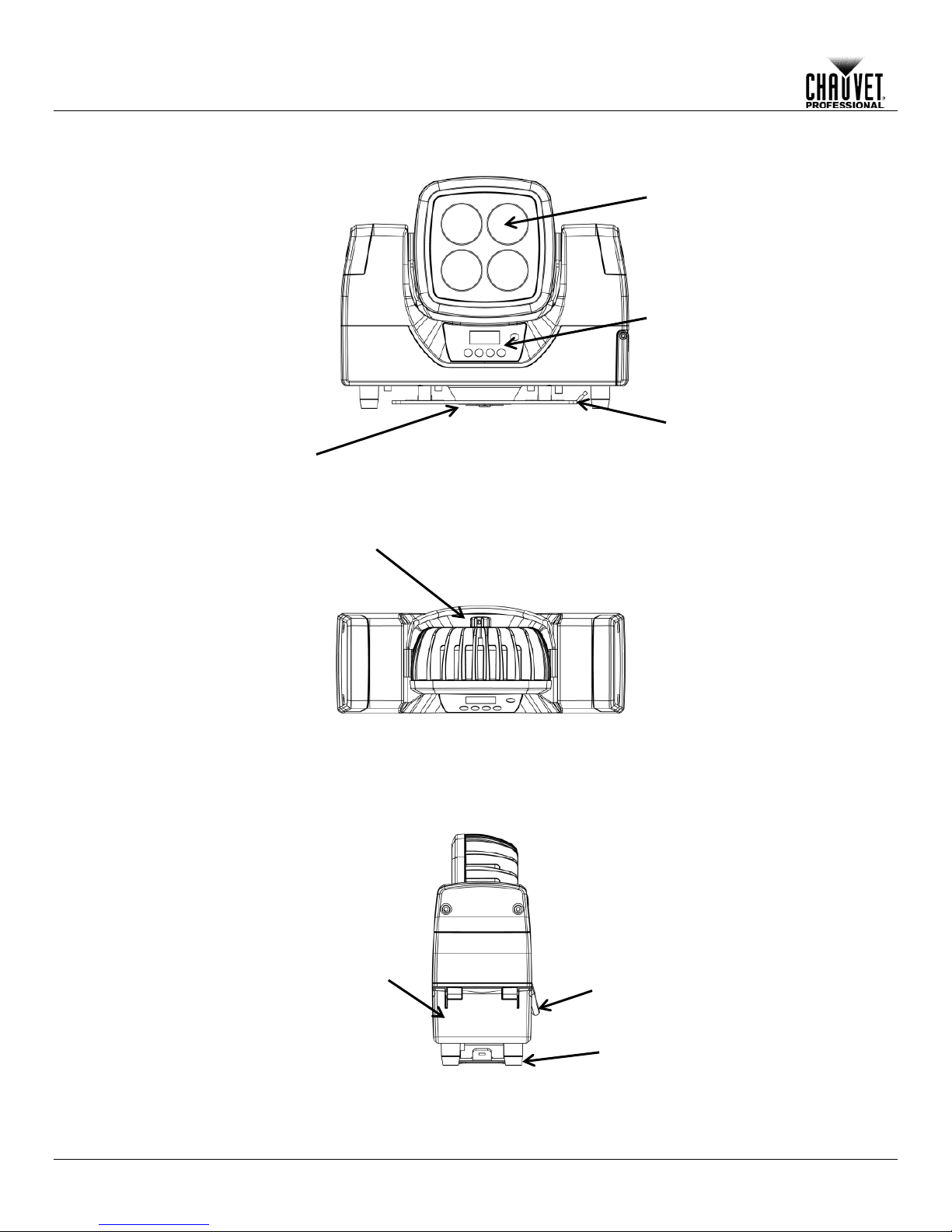
Front View
Rear View
Side View
LED
Zoom Adjustment
Control Panel
Power/Data
Access
Panel
Handle
Mounting
Plate
Case Charger Input
Rubber feet
Introduction
Overview
-4- WELL™ Flex User Manual Rev. 1
Page 9

Dimensions
12.28 in
312 mm
4.25 in
108 mm
9.85 in
250 mm
7.84 in
199 mm
Introduction
WELL™ Flex User Manual Rev. 1 -5-
Page 10

AC Power
Each WELL™ Flex has an auto-ranging batter y charg er, w het her s tan d -alo ne or i nside t he f li ght
50/60 Hz. To determ ine the
:
http://www.chauvetlighting.com/download/.
Always connect this product to a protected circuit with an appropriate electrical ground
to avoid the risk of electrocution or fire.
Never connect this product to a rheostat (variable resistor) or dimmer circuit, even if the
rheostat or dimmer channel serves only as a 0 to 100% switch.
AC Plug
The WELL™ Flex com es with a power input cord terminated with a Neutrik® powerCON® A
table below to wire the new plug.
AC Live
Black
Brown
Yellow or Brass
AC Neutral
White
Blue
Silver
AC Ground
Green/Yellow
Green/Yellow
Green
Battery Charge
• Recharge the battery within three days from last use.
• Perform a full discharge/recharge cycle every three months.
Be sure to remove rubber plug from the bottom of the product before charging in the
road case.
Replacing the
Fuse
The WELL™ Flex has no external fuse. However, the road case charger comes with a
4. Screw the fuse holder cap back in place and reconnect power.
Setup
3. SETUP
case that works with an in put voltage range of 100 to 240 VAC,
power requirements f or each WELL™ Flex, refer to the l abel affixed to the product. You can
also refer to the
The listed current r ati ng in d icates t he maximum current draw duri ng nor mal operation. For m ore
information, you may download Sizing Circuit Breakers from the Chauvet website
connector on one end and an Edison plug on the other end (U.S. mark et). If the power input
cord that came with your product has no plug, or if you nee d to c h ang e th e Ediso n plug, use the
Connection Wire (U.S.) Wire (Europe) Screw Color
Technical Specificat io ns chart in this manual.
Notes
• Recharge the battery to full capacity before storing this product.
• For best results, charge the battery in a temperature between 32 ºF (0 ºC) and
95 ºF (35 ºC).
• When charging the battery, keep the product at no less than 1 m from any open flame or
hot plate.
• When charging the battery inside the road case charger, keep the road case’s cover open.
• Always charge the battery with the product in an upright position.
• Do not charge the battery for more than 24 hours.
replaceable fuse.
1. Disconnect this product from power.
2. Using a flat-head screwdriver, unscrew the fuse holder cap from the housing.
3. Remove blown fuse and replace with a good fuse of the same type and rating.
-6- WELL™ Flex User Manual Rev. 1
Page 11

Setup
DMX Linking
You can link the W ELL™ Flex to a DMX controller using a 5-pi n DMX con nect ion. If using o ther
DMX controller.
DMX
The W ELL™ Flex uses a 5-pin DMX data connection for the 3-, 4-, 6- and 10-channel DMX
personalities.
If you are not familiar with or need more information about DMX standards, Master/Slave
connectivity, or the DMX cables needed to link this product to a DMX controller,
http://www.chauvetlighting.com/download/.
Master/Slave
The Master/Slave mode allows a WELL™ Flex (the master) to control one or more WELL™
n
operation, the slaves will operate in unison with the master.
Master/Slave mode not available in wireless operation.
configure the master and slaves.
DMX-compatible prod ucts with the W ELL™ F lex, you c an control each indi vidually with a single
Personalities
Connectivity
personalities.
• Refer to the Introduction chapter for a brief description of each DMX personality.
• Refer to the Operation chapter to learn how to configure the WELL™ Flex to work in these
personalities.
• The DMX Values section provides you with detailed information regarding the DMX
download the DMX Primer from the Chauvet website:
Flex’s (the slaves) without a DMX controller. One WELL™ Flex becomes the master whe
running an auto program, or by being in a Static mode.
You must configure each s lave’s control panel to op erate in Slave mode. During Master/Slave
DO NOT connect a DMX controller to products operating in Master/Slave m ode. T he DM X
controller signals may interfere with the signals from the master.
•
• The Operation section of this manual provides detailed instructions on how to
WELL™ Flex User Manual Rev. 1 -7-
Page 12

Wireless
Operation
The WELL™ Flex can operate in W-DMX™ mode up to 50 m (164 ft) from the
be paired with the
W-DMX™ transmitter for wireless operation.
Initial Setup
1. Turn the W-DMX™ transmitter on.
5. Turn the WELL™ Flex on.
Configuration
1. From the WELL™ Flex’s control panel, go to DM X Address.
established.)
Product Pairing
If the WELL™ Flex has a lread y been paired with the W-DMX™ transmitter, the Signal Stre ngth
show the strength of the signal.
Storage Notes
• Recharge the battery to full capacity before storing the product.
• Store charged product(s) in a dry environment, away from direct sunlight.
W-DMX™ operation can be interrupted or inhibited by liquid masses between the
between the transmitter and receiver clear of any liquid mass.
Control Panel
W-DMX™ Transmitter
Setup
W-DMX™ transmitter. The W-DMX™ receiver in the WELL™ Flex must
2. Connect the W-DMX™ transmitter to a DMX controller.
3. Place the WELL™ Flex within 50 m from the W-DMX™ transmitter.
4. Disconnect any DMX cable from the WELL™ Flex.
2. Select the start address, as with any other DMX compatible product.
3. Go to Wireless Setting > Receive.
4. Select On. (The Signal Strength Indicator w ill show a ? in front of the bars)
5. Press the reset button on the W-DMX™ transmitter. (The Signal Strength Indicator on the
WELL™ Flex will show a ϟ in front of the bars for 3 seconds while a connection is
Indicator in the middle of the LCD screen will show t he strength of the signa l. In this case, the
WELL™ Flex is ready to work in Wireless mode.
Pairing the WELL™ Flex and a new W-DMX™ transmitter:
1. From the WELL™ Flex’s control panel, go to Wireles s Sett ing .
2. Select Reset. The Signal Strength Indicator on the WELL™ Flex will show a ? in front of the
bars.
3. From the W-DMX™ transmitter, press <RESET> (the Signal Indicator on the transmitter will
flash).
4. Once the transmitter has found the WELL™ Flex, the Signal indicator on the W-DMX™
transmitter will illuminate solid.
5. The Signal Strength Indicator in the middle of the LCD screen on the WELL™ Flex will
transmitter and receiv er such as water, snow , or people. For best result s, keep the area
W-DMX™ Setup
-8- WELL™ Flex User Manual Rev. 1
Page 13

Setup
Mounting
Before mounting this product, read and follow the Safety Notes. For our CHAUVET®
Professional line of mounting clamps, go to http://trusst.com/products/.
Orientation
Always mount this product in a safe position and make sure there is adequate room for
Rigging
Chauvet recommends using the following general guidelines when mounting this product.
• When selecting an installation location, consider easy access to this product for operation,
our CHAUVET® Professional line of safety cables, go to http://trusst.com/products/.
Procedure
The WELL™ Flex comes with preinstalled mounting to which you will be able to attach the
You may
the product
When using only one mounting clamp, be sure to use a clamp with a captive bolt to
prevent accidental loosening.
Floor Mounting
Overhead Mounting
Clamp
Omega
Bracket
ventilation, configuration, and maintenance.
programming adjustments, and routine maintenance.
• The product is not intended for permanent outdoor installation.
• Make sure to mount this product away from any flammable material as indicated in the
Safety Notes
• Never mount in places where rain, high humidity, extreme temperature changes, or
restricted ventilation may affect the product. (IP44)
• If hanging this product, make sure that the mounting location can support the product’s
weight. See the Tec hnic al Specif icat io ns
product.
• When hanging this product, always secure to a fastening device using a safety cable. For
included om ega brack et. Use one m ounting poin t per produc t. In addit ion, use a s afety cable to
link the product to the stru cture. You must supply your own mounting cl amps. Make sure the
clamps are capable of supporting the weight of this product. Use at least one mounting point per
product. For our Chauvet line of mounting c lamps, go to
also choose to simpl y set the WELL™ Flex on the floor using the rubber feet on the bot tom of
.
for the weight-bearing requirements of this
http://trusst.com/products/.
Mounting Diagram
WELL™ Flex User Manual Rev. 1 -9-
Page 14

Control Panel
Button
Function
<ON/OFF>
Press and hold to turn product on or off
<MENU>
Exits from the current menu or function
<ENTER>
Enables the currently displayed menu or sets the currently selected
value in to the current function
<UP>
Navigates upward through the menu list or increases the numeric
value when in a function
<DOWN>
Navigates downward through the menu list or decreases the numeric
value when in a function
Control
Options
Programming
Refer to the Menu Map to understand th e menu options. The menu m ap shows the main level
• Press <MENU> repeatedly to exit to the previous main level.
Zoom
Adjustment
You can manually adjust the zoom angle of the WELL™ Flex by adjusting the knob on the back
clockwise will widen the beam.
Tilt Adjustment
The head of the WELL™ Flex can be manually adjusted up to 220°.
220°
Zoom
22° to 31°
Operation
4. OPERATION
Description
You can set the WELL™ Flex starting address in the 001–512 DMX range. This e nab les c on tr ol
of up to 51 products in the 10-channel 10Ch personality.
and a variable number of programming levels for each option.
• To go to the desired main level, press <MENU> repeatedly until the option shows on the
• To select an option or value within the current programming level, press <UP> or <DOWN>
display. Press <ENTER> to select. This will take you to the first programming level for that
option.
until the option shows on the display. Press <ENTER> to select. In this case, if there is
another programming level, you will see that first option, or you will see the selected value.
of the head. Tur ning the knob clockwise will narro w the beam while turning the k nob counter
Procedure
Adjustment
-10- WELL™ Flex User Manual Rev. 1
Page 15

Menu Map
Auto Show
Auto 0–4
Speed
0–100
Automatic programs and speed
R
Red
G
Green
B
Blue
W
White
GB
Green/Blue
RB
Red/Blue
RG
Red/Green
RGB
Red/Green/Blue
RW
Red/White
GW
Green/White
BW
Blue/White
RGW
Red/Green/White
RBW
Red/Blue/White
GBW
Green/Blue/White
RGBW
Red/Green/Blue/White
R
G B W
Off
No dimmer
Dimming curves Dimmer 1 (fast) to Dimmer 3
(slow)
Turns off display backlight after 10 sec of
inactivity
Turns off display backlight after 20 sec of
inactivity
Turns off display backlight after 30 sec of
inactivity
On
Display backlight alwa ys on
Test
Turns on all LEDs in sequence for testing
Fixture Hours
Shows total product hours
Version
Shows installed software ver sion
Main Level Programming Levels Description
Static
Operation
Fixed Color
Manual
Color
Dimmer Mode
Back Light
Information
Value 0–255
Dimmer 1–3
10S
20S
30S
Combines red, green, blue, and white to make
a custom color (0–100%)
WELL™ Flex User Manual Rev. 1 -11-
Page 16

Selects DMX address (highest channel
restricted to personality chosen)
4 Ch
4-channel: RGBW control
6 Ch
6-channel: RGBW control, dimmer, and strobe
10-channel: RGBW control, dimmer, strobe,
auto speed, dimmer speed
HSV
3-channel: HSV control
HSI
3-channel: HSI control
Master
DMX mode (Master)
Slave
Slave mode
On
Off
Reset
Resets the wireless setting
R
Sets red LED maximum value
G
Sets green LED maximum value
B
Sets blue LED maximum value
Operation
Menu Map (Cont.)
Main Level Programming Levels Description
DMX Address 001–512
DMX Channel
Master/Slave Mode
Wireless Setting
White Balance Balance
Receive
10Ch
Value 125–255
color macro/white balance, auto progr ams,
Turns wireless DMX function on/off
-12- WELL™ Flex User Manual Rev. 1
Page 17

Configuration
(Standalone)
Use standalone configuration to operate the product without a DMX controller.
Automatic
Automatic programs allow for dynamic RGBW color mixing without a DMX controller.
4. Select the desired speed 0–100.
Fixed Static
The fixed static color mode allows for preset RGBW color mixing without a DMX controller.
3. Select the desired color combination. See Menu Map.
Manual Static
The manual static color mode allo ws for manually customizable RGBW color mixing without a
6. Repeat for the other colors.
Master/Slave
The Master/Slave mode allows a group of WELL™ Flex’s (the slaves) to simultaneously
colors as explained in Fixed Static Color or Manual Static Color.
• The master is the one that runs a program whether in automatic programs, fixed
• The master should be the first product in the daisy chain.
Operation
Programs
Color
Color
1. Go to the Auto Show main level.
2. Select the desired automatic (Auto 0–4) program.
3. Go to the Speed program m ing leve l.
You cannot edit any of the automati c programs (Auto 0–4).
1. Go to the Static main level.
2. Select the Fixed Color programming level.
DMX controller.
1. Go to the Static main level.
2. Select the Manual Color programming level.
3. Select the desired color R, G, B or W.
4. Go to the Value programming option.
5. Select the desired color value 0–255 (0–100%).
duplicate the output of another WELL™ Flex (the master) without a DMX controller.
1. Set each of the slaves:
a. Go to the Master/Slave Mode main level.
b. Select Slave.
2. Set the master:
a. Go to the Master/Slave Mode main level.
b. Select Master.
c. Select an automatic program as explained in Automatic Programs
, or a static mix of
static color or manual static color modes.
• Do not connect a DMX controller to the products configured for Master/Slave
operation. The DMX controller may interfere with signals from the master.
WELL™ Flex User Manual Rev. 1 -13-
Page 18

Dimmer Profiles
This setting determines how fas t the output of the WELL™ Flex changes when you m odify the
2. Select a dimmer profile (Off, Dimmer 1, Dimmer 2, or Dimmer 3).
OFF:
The output is proportional (linear) to the dimmer and RGBW channel values.
Dimmer 1–3:
The output follows the dimmer and RGBW channel values based on the
slowest.
White Calibration
This setting allows you to select the white color shown by the WELL™ Flex when the DMX
6. Repeat for the other colors.
When selecting White Balance, you will only be able to define the values of red (R),
green (G), and blue (B).
The values of red (R), green (G), and blue (B) configured from White Balance will define
the color temperature shown when the RGB faders are set to 255.
Backlight
This setting allows you to set the amount of time the backlight on the
2. Select On (remains on), 10S (10 seconds), 20S (20 seconds), or 30S (seconds).
Software
This option shows what version of software the WELL™ Flex is running.
2. Select Version and the version number will show on the display.
Fixture Hours
This option shows the total amount of hours the WELL™ Flex has been turned on.
2. Select Fixture Hours and the total number of hours will show on the display.
LED Test
This option runs a check of the LEDs on the WELL™ Flex by turning on all the LEDs in
2. Select Test programming level.
Operation
values of the red, green, blue, white , and dimmer faders. This setting provides three different
options to simulate the dimming curve of an incandescent lighting product.
1. Go to the Dimmer Mode main level.
Information
corresponding dimmer curve, Dimmer 1 being the fastest and Dimmer 3 the
controller’s red, green, and blue faders are set to 255.
1. Go to the White Balance main level.
2. Go to Balance.
3. Select a color (R, G, or B).
4. Go to Value.
5. Select a color value (125–255).
WELL™ Flex’s display stays on after the last button is pressed on the control panel.
1. Go to the BackLite main level.
1. Go to the Information main level.
1. Go to the Information main level.
sequence.
1. Go to the Information main level.
-14- WELL™ Flex User Manual Rev. 1
Page 19

Configuration
(DMX)
Use DMX configurations to operate the product with a DMX controller.
DMX
This setting allows you to choose a particular DMX personality.
2. Select the desired personality (4 Ch, 6 Ch, 10Ch, HSI, or HSV).
• See the DMX Values section for the highest starting address you can select for each
the new personality setting.
DMX Control
In this mode, each product will respond to a unique starting address from the DMX controller. All
b. Select the starting address (001–512).
The highest recommended starting address for each DMX mode is as follows:
4 Ch
509
6 Ch
507
10Ch
503
HSI
510
HSV
510
Wireless Settings
This mode allows you to co ntrol DMX wir elessl y. For detailed s etup of this f eature see Wireless
2. Select Off.
Operation
Personalities
1. Go to the DMX Channel main level.
personality.
• Make sure that the starting addresses on the various products do not overlap due to
products with the same starting address will respond in unison.
1. Select a DMX personality as shown in DMX Personalities.
2. Set the starting address:
a. Go to DMX Address main level.
DMX Personality DMX Address
Operation. To disable this feature:
1. Go to Wireless Setting > Receive.
WELL™ Flex User Manual Rev. 1 -15-
Page 20

10Ch
1
Dimmer
000 ó 255
0–100%
2
Red
000 ó 255
0–100%
3
Green
000 ó 255
0–100%
4
Blue
000 ó 255
0–100%
5
White
000 ó 255
0–100%
000 ó 010
011 ó 255
No function
Slow to fast
000 ó 010
251 ó 255
No function
White 11
000 ó 051
255
No function
Auto 5
9
Auto Speed
000 ó 255
Slow to fast
000 ó 051
204 ó 255
Preset dimmer speed from display menu
Nonlinear dimming curve 3 (slowest)
Operation
DMX Values
Channel Function Value Percent/Setting
6 Strobe
011 ó 030
031 ó 050
051 ó 070
071 ó 090
091 ó 110
111 ó 130
131 ó 150
151 ó 170
171 ó 200
201 ó 205
206 ó 210
7
Color Macro + White
Balance
211 ó 215
216 ó 220
221 ó 225
226 ó 230
231 ó 235
236 ó 240
241 ó 245
246 ó 250
052 ó 101
8 Auto Programs
102 ó 152
153 ó 203
204 ó 254
R: 100% G: 0–100% B: 0
R: 100%–0 G: 100% B: 0
R: 0 G: 100% B: 0–100%
R: 0 G: 100%–0 B: 100%
R: 0–100% G: 0 B: 100%
R: 100% G: 0 B: 100%–0
R: 100% G: 0–100% B: 0–100%
R: 100%–0 G: 100%–0 B: 100%
R: 100% G: 100% B: 100% W: 100%
White 1
White 2
White 3
White 4
White 5
White 6
White 7
White 8
White 9
White 10
Auto 1
Auto 2
Auto 3
Auto 4
10 Dimmer Speed
-16- WELL™ Flex User Manual Rev. 1
052 ó 101
102 ó 152
153 ó 203
Linear dimmer
Nonlinear dimming curve 1 (fastest)
Nonlinear dimming curve 2
Page 21

DMX Values (Cont.)
6 Ch
1
Dimmer
000 ó 255
0–100%
2
Red
000 ó 255
0–100%
3
Green
000 ó 255
0–100%
4
Blue
000 ó 255
0–100%
5
White
000 ó 255
0–100%
000 ó 010
011 ó 255
No function
Slow to fast
4 Ch
1
Red
000 ó 255
0–100%
2
Green
000 ó 255
0–100%
3
Blue
000 ó 255
0–100%
4
White
000 ó 255
0–100%
HSV
Channel
Function
Value
Percent/Setting
1
Hue
000 ó 255
0–100%
2
Saturation
000 ó 255
0–100%
3
Value
000 ó 255
0–100%
HSI
1
Hue
000 ó 255
0–100%
2
Saturation
000 ó 255
0–100%
3
Intensity
000 ó 255
0–100%
Channel Function Value Percent/Setting
6 Strobe
Channel Function Value Percent/Setting
Operation
Channel Function Value Percent/Setting
WELL™ Flex User Manual Rev. 1 -17-
Page 22

Product
To maintain optim um performance and minim ize wear , you s ho uld c le an this product frequently.
light output
performance and can cause overheating. This can lead to reduced light source life and
7. Gently polish the lens surfaces until they are free of haze and lint.
Technical Information
5. TECHNICAL INFORMATION
Maintenance
Usage and environment are contributing factors in determining the cleaning frequency.
As a rule, clean this product at least twice a month. Dust build-up reduces
increased mechanical wear.
To clean your product:
1. Unplug the product from power.
2. Wait until the product is at room temperature.
3. Use a vacuum (or dry compressed air) and a soft brush to remove dust collected on the
external vents.
4. Clean all external surfaces with a mild solution of non-ammonia glass cleaner or isopropyl
alcohol.
5. Apply the solution directly to a soft, lint-free cotton cloth or a lens cleaning tissue.
6. Wipe any dirt or grime to the outside edges of the lens surface.
Always dry the external surfaces thoroughly and carefully after cleaning them.
-18- WELL™ Flex User Manual Rev. 1
Page 23

6. TECHNICAL SPECIFICATIONS
Dimensions and
4.25 in (108 mm)
12.28 in (312 mm)
9.85 in (250 mm)
12 lb (5.4 kg)
Note: Dimensions in inches rounded to the nearest decimal digit.
Power
Switching (internal)
100–240 VAC, 50/60 Hz
Auto-ranging
Consumption
(Single Product)
68 W
82 W
Consumption
(Flight Case)
364 W
487 W
Operating(Single Product)
0.57 A
0.35 A
Operating (Flight Case)
2.9 A
1.3 A
Fuse (Flight Case)
T 5 A, 250 V
T 5 A, 250 V
Power I/O
U.S./Canada
Worldwide
Power input connector
(Single product)
Neutrik® powerCON® A
Neutrik® powerCON® A
Power input connector
(Flight case)
Neutrik® powerCON® A
Neutrik® powerCON® A
Power cord plug
Edison (U.S.)
Local plug
Light Source
LED
10 W
50,000 hours
Quad-color RGBW
4
750 mA
Photometrics
Parameter
Narrow
Wide
Illuminance @ 5 m
533 lux
510 lux
Beam angle
12°
18°
Field angle
22°
31°
Thermal
113 °F (45 °C)
Convection
DMX
5-pin XLR
Sockets
3, 4, 6 or 10
Ordering
WELL™ Flex
03030873
781462212216
WELL™ Flex x6
03030874
781462212223
Technical Specifications
Weight
Length Width Height Weight
Power Supply Type Range Voltage Selection
Parameter 120 VAC, 60 Hz 230 VAC, 50 Hz
Type Power Lifespan
Max. External Temperature Cooling System
Color Quantity Current
I/O Connectors Connector Type Channel Range
Product Name Item Code UPC Number
-19-
Page 24

Returns
You must send the product prepaid, in the original box, and with the original packing and
will refuse any product returned
without an RMA number.
DO NOT write the RMA number directly on the box. Instead, write it on a properly affixed
label.
Once you have rec ei ved t he RMA number, include t he f ollo wing information on a piec e of pa per
Be sure to pack the product properly. Any shipping damage resulting from inadequate
recommended.
Chauvet reserves the right to use its own discretion to repair or replace returned
product(s).
Technical Specifications
accessories. Chauvet will not issue call tags.
Call Chauvet and reques t a Return Merchandise Authorizat ion (RMA) number before shippin g
the product. Be prepared to provide th e m odel num ber, s erial num ber, and a br ief desc ription of
the cause(s) for the return.
Clearly label the package with an RMA number. Chauvet
inside the box:
• Your name
• Your address
• Your phone number
• The RMA number
• A brief description of the problem(s)
packaging will be the customer’s responsibility. FedEx packing or double-boxing is
-20-
Page 25

C
WORLD HEADQUARTERS - Chauvet
General Information
Toll free:(800) 762-1084
Technical Support
World Wide Web www.chauvetlighting.com
UNITED KINGDOM AND IRELAND - Chauvet Europe Ltd.
General Information
Fax: +44 (0)1773 511110
Technical Support
MEXICO - Chauvet Mexico
General Information
Voice: +52 (728) 285-5000
Technical Support
Outside the U.S., United Ki ngdom, Ireland, or Mexico, contact the deal er of record. Follo w their
instructions to request support or to return a product. Visit our website for contact details.
User Manual
ONTACT
US
Address:5200 NW 108th Avenue
Sunrise, FL 33351
Voice: (954) 577-4455
Fax: (954) 929-5560
Address:Unit 1C
Brookhill Road Industrial Estate
Pinxton, Nottingham, UK
NG16 6NT
Voice: +44 (0)1773 511115
Address:Av. Santa Ana 30
Parque Industrial Lerma
Lerma, Mexico C.P. 52000
Voice: (954) 577-4455 (Press 4)
Fax: (954) 756-8015
Email: tech@chauvetlighting.com
Email: uktech@chauvetlighting.com
World Wide Web www.chauvetlighting.co.uk
Email: servicio@chauvet.com.mx
World Wide Web www.chauvet.com.mx
 Loading...