

Page 1
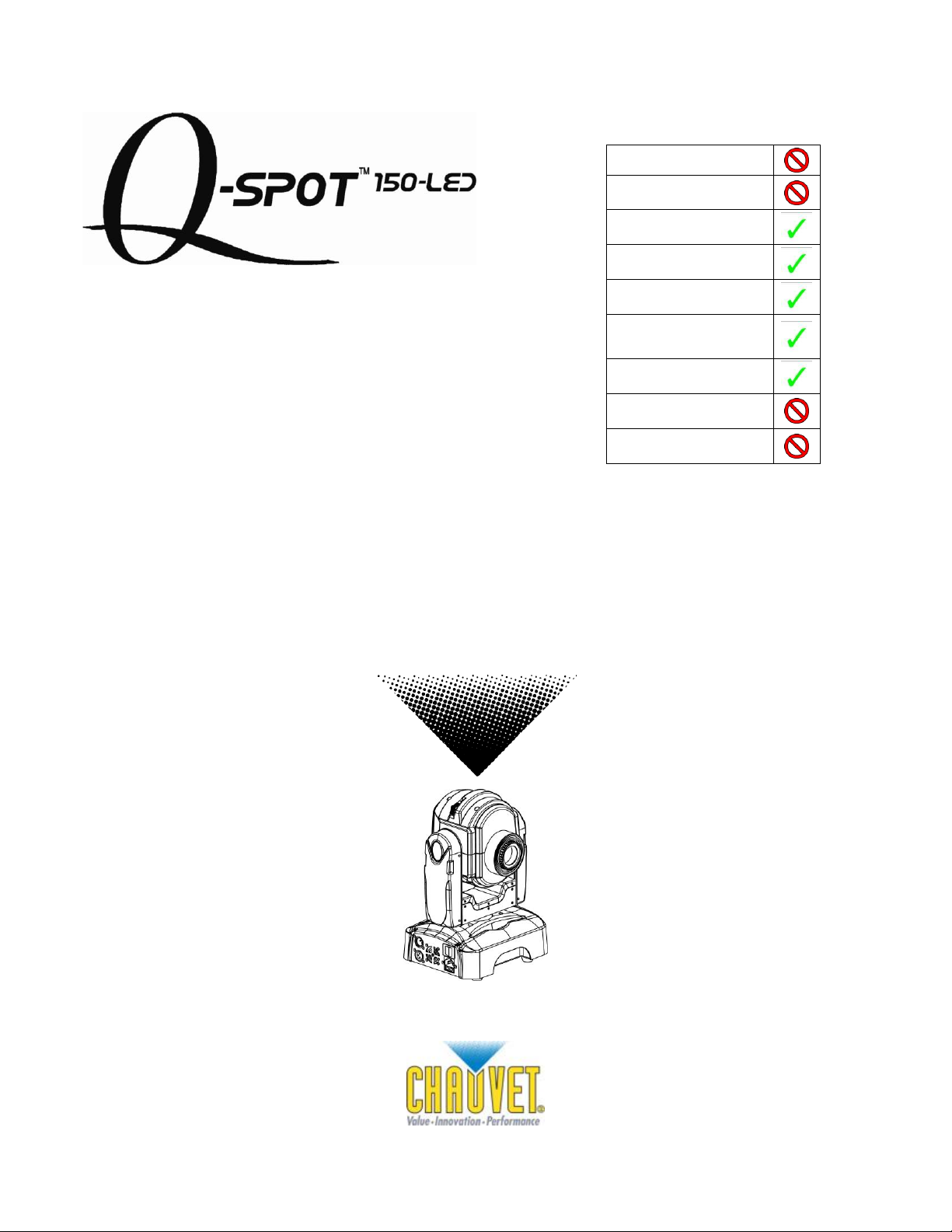
Snapshot
OK on Dimmer
Outdoor OK
Sound Activated
DMX512
Master/Slave
Autoswitching
transformer
Replaceable Fuse
User Serviceable
Duty Cycle
USER MANUAL
3000 N 29th Ct, Hollywood, FL 33020 U.S.A.
(800) 762-1084 – (954) 929-1115
FAX (954) 929-5560
www.chauvetlighting.com
Page 2

TABLE OF CONTENTS
1. BEFORE YOU BEGIN ................................................................................................................................................... 3
WHAT IS INCLUDED ................................................................................................................................................................................ 3
UNPACKING INSTRUCTIONS .................................................................................................................................................................... 3
AC POWER........................................................................................................................................................................................... 3
CONTACT US ........................................................................................................................................................................................ 3
SAFETY INSTRUCTIONS .......................................................................................................................................................................... 4
2. INTRODUCTION ........................................................................................................................................................... 5
FEATURES ............................................................................................................................................................................................ 5
DMX CHANNEL SUMMARY ..................................................................................................................................................................... 5
PRODUCT OVERVIEW............................................................................................................................................................................. 6
PRODUCT DIMENSIONS .......................................................................................................................................................................... 7
3. SETUP .......................................................................................................................................................................... 8
Fuse Replacement .................................................................................................................................................... 8
REPLACING GOBOS ............................................................................................................................................................................... 8
GOBO AND COLOR WHEEL DIAGRAMS .................................................................................................................................................... 9
FIXTURE LINKING................................................................................................................................................................................. 10
Data Cabling ........................................................................................................................................................... 10
DMX Data Cable ..................................................................................................................................................... 10
Cable Connectors ................................................................................................................................................... 10
3-Pin to 5-Pin Conversion Chart .............................................................................................................................. 11
SETTING UP A DMX SERIAL DATA LINK ................................................................................................................................................. 11
MASTER/SLAVE FIXTURE LINKING ......................................................................................................................................................... 11
MOUNTING.......................................................................................................................................................................................... 12
Orientation .............................................................................................................................................................. 12
Rigging ................................................................................................................................................................... 12
4. OPERATING INSTRUCTIONS .................................................................................................................................... 13
NAVIGATING THE CONTROL PANEL........................................................................................................................................................ 13
MENU MAP ......................................................................................................................................................................................... 14
MENU MAP ......................................................................................................................................................................................... 14
MENU FUNCTIONS ............................................................................................................................................................................... 15
Service Functions ................................................................................................................................................... 15
To test the fixture: ................................................................................................................................................... 15
To reset the fixture: ................................................................................................................................................. 15
To restore all settings to their factory defaults: ........................................................................................................ 15
OPERATION ........................................................................................................................................................................................ 15
Master/Slave Mode (Master Sound, Master Auto): .................................................................................................. 15
DMX Mode .............................................................................................................................................................. 15
DMX CHANNEL VALUES ...................................................................................................................................................................... 15
Setting the DMX Starting Address ........................................................................................................................... 18
5. APPENDIX .................................................................................................................................................................. 18
DMX PRIMER ..................................................................................................................................................................................... 18
GENERAL MAINTENANCE...................................................................................................................................................................... 19
RETURNS PROCEDURE ........................................................................................................................................................................ 19
CLAIMS .............................................................................................................................................................................................. 19
Q-SPOT™ 150-LED TROUBLESHOOTING ............................................................................................................................................. 20
TECHNICAL SUPPORT .......................................................................................................................................................................... 20
EXPLODED VIEW ........................................................................................................................................................... 21
PHOTOMETRICS .................................................................................................................................................................................. 22
TECHNICAL SPECIFICATIONS ................................................................................................................................................................ 22
Q-Spot™ 150-LED User Manual 2 9/22/2009 3:57 PM
Page 3

1. BEFORE YOU BEGIN
What is included
1 x Q-Spot™ 150-LED
1 x Set of 3 extra gobos
1 x Bracket set
1 x Power Cord
1 x Warranty Card
1 x User Manual
Unpacking Instructions
Immediately upon receiving a fixture, carefully unpack the carton, check the contents to ensure that
all parts are present, and have been received in good condition. Notify the shipper immediately and
retain packing material for inspection if any parts appear damaged from shipping or the carton itself
shows signs of mishandling. Save the carton and all packing materials. In the event that a fixture
must be returned to the factory, it is important that the fixture be returned in the original factory box
and packing.
AC Power
This fixture has an auto-switching power supply that can accommodate a wide range of input
voltages. The only thing necessary to do before powering on the unit is to make sure the line voltage
you are applying is within the range of accepted voltages. This fixture will accommodate between 100
V and 240 VAC, 50/60 Hz. All fixtures must be powered directly off a switched circuit and cannot be
run off a rheostat (variable resistor) or dimmer circuit, even if the rheostat or dimmer channel is used
solely for a 0% to 100% switch.
Warning! All fixtures must be connected to circuits with a suitable Earth Ground.
Contact Us
World Wide
General Information CHAUVET
Technical Support CHAUVET
World Wide Web www.chauvetlighting.com
3000 North 29th Court
Hollywood, FL 33020
voice: 954.929.1115
fax: 954.929.5560
toll free: 800.762.1084
3000 North 29th Court
Hollywood, FL 33020
voice: 954.929.1115 (Press 4)
fax: 954.929.5560 (Attention: Service)
Q-Spot™ 150-LED User Manual 3 9/22/2009 3:57 PM
Page 4
Safety Instructions
Please read these instructions carefully, which includes important
information about the installation, usage and maintenance of this
product.
Please keep this User Guide for future consultation. If you sell the unit to another user, be sure that
they also receive this instruction booklet.
Always make sure that you are connecting to the proper voltage, and that the line voltage you are
connecting to is not higher than that stated on the decal or rear panel of the fixture.
This product is intended for indoor use only! To prevent risk of fire or shock, do not expose fixture to
rain or moisture.
Make sure there are no flammable materials close to the unit while operating.
The unit must be installed in a location with adequate ventilation, at least 20 in (50 cm) from adjacent
surfaces. Be sure that no ventilation slots are blocked.
Always disconnect from power source before servicing or replacing parts or fuse and be sure to
replace with same parts.
Secure fixture to fastening device using a safety chain. Never carry the fixture solely by its head. Use
its carrying handles.
Maximum ambient temperature (Ta) is 104° F (40° C). Do not operate fixture at temperatures higher
than this.
In the event of a serious operating problem, stop using the unit immediately. Never try to repair the
unit by yourself. Repairs carried out by unskilled people can lead to damage or malfunction. Please
contact the nearest authorized technical assistance center.
Never connect the device to a dimmer pack.
Make sure the power cord is never crimped or damaged.
Never disconnect the power cord by pulling or tugging on the cord.
Avoid direct eye exposure to the light source while it is on.
Caution! There are no user serviceable parts inside the unit. Do not open the housing or
attempt any repairs yourself. In the unlikely event your unit may require service,
please contact CHAUVET at: 954-929-1115.
Q-Spot™ 150-LED User Manual 4 9/22/2009 3:57 PM
Page 5
2. INTRODUCTION
CHANNEL
FUNCTION (ADVANCED MODE)
CHANNEL
FUNCTION (BASIC MODE)
1
Pan
1
Pan 2 Pan fine
2
Tilt 3 Tilt
3
Color
4
Tilt fine
4
Gobo
5
Pan/Tilt Speed
5
Gobo rotate
6
Color
6
Prism
7
Gobo
7
Dimmer
8
Gobo rotate
8
Strobe
9
Prism
9
Control
10
Dimmer
11
Strobe
12
Control
Features
9 or 12-channel DMX LED moving yoke
Pan: 530º / Tilt: 270º
Color wheel
Rotating gobo wheel with gobo shake
3-facet prism
Variable electronic strobe
Variable electronic dimmer (0 – 100%)
Remote fixture reset
255 user-programmable steps without DMX controller
Move-in-black for pan/tilt
Built-in automated programs
Built-in sound activated programs
1 High-powered, 20 W (1000 mA) LED
User-selectable pan/tilt ranges
Automatic pan/tilt correction
Reset to factory settings option
User-selectable basic or advanced operating modes
9 colors + white
Rainbow color spin at variable speeds
7 interchangeable, slot-n-lock gobos + open
Gobo wheel spin at variable speeds
Additional Features
DMX Channel Summary
Q-Spot™ 150-LED User Manual 5 9/22/2009 3:57 PM
Page 6
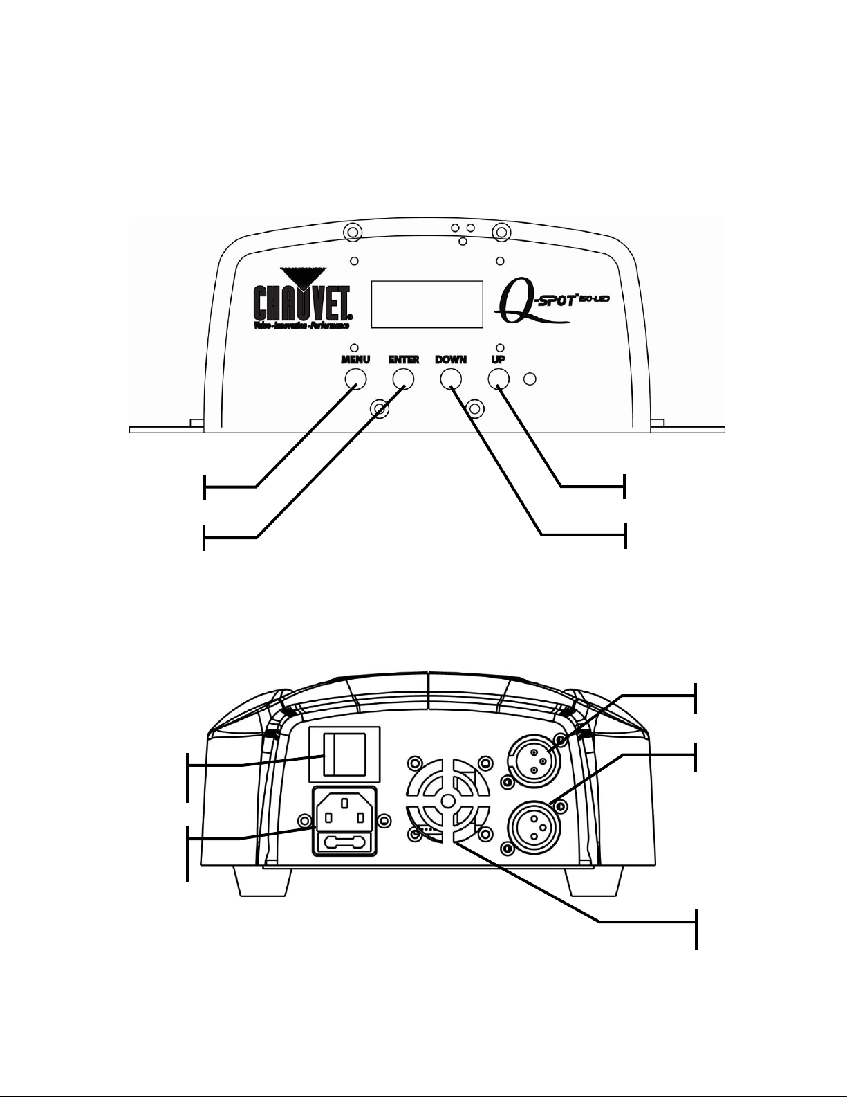
Product Overview
DMX in
Up
Enter
Menu
Down
Power
on/off
switch
Power
input/fuse
holder
Cooling fan
vent
DMX out
Q-Spot™ 150-LED User Manual 6 9/22/2009 3:57 PM
Page 7
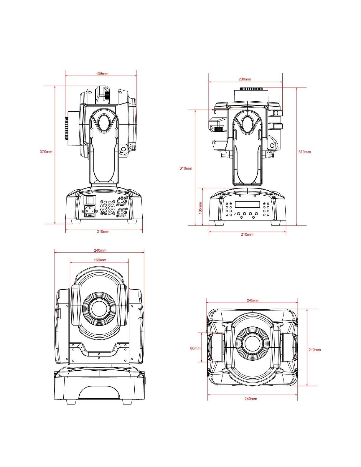
Product Dimensions
Q-Spot™ 150-LED User Manual 7 9/22/2009 3:57 PM
Page 8

3. SETUP
Disconnect the power cord before replacing a fuse and always
replace with the same type fuse.
Fuse Replacement
1) With a flat head screwdriver wedge the fuse holder
out of its housing.
2) Remove the damaged fuse from its holder and
replace with exact same type and rating fuse.
3) Insert the fuse holder back in its place.
4) Reconnect power.
Replacing Gobos
1) Remove the gobo cover.
2) Remove the slot-n-lock gobo from the gobo wheel.
3) Using a small tool, pry the tension ring from the gobo holder.
4) Remove the old gobo.
5) Insert the new gobo, and replace in the
reverse steps of removal.
Q-Spot™ 150-LED User Manual 8 9/22/2009 3:57 PM
Page 9

Gobo and Color Wheel Diagrams
Q-Spot™ 150-LED User Manual 9 9/22/2009 3:57 PM
Page 10

Fixture Linking
COMMON
DMX +
DMX -
INPUT
OUTPUT
1 3 2
1
3
2
1
3
2
Resistance 120
ohm 1/4w between
pin 2 (DMX -) and
pin 3 (DMX +) of
the last fixture.
Termination reduces signal errors. To
avoid signal transmission problems
and interference, it is always
advisable to connect a DMX signal
terminator.
DMX connector configuration
You will need a serial data link to run light shows of one or more fixtures using a DMX controller or to
run synchronized shows on two or more fixtures set to a master/slave operating mode. The combined
number of channels required by all the fixtures on a serial data link determines the number of fixtures
the data link can support.
Important: Fixtures on a serial data link must be daisy chained in one single line. To comply with the EIA-
485 standard no more than 32 devices should be connected on one data link. Connecting more
than 32 fixtures on one serial data link without the use of a DMX optically-isolated splitter may
result in deterioration of the digital DMX signal.
Maximum recommended serial data link distance: 500 meters (1640 ft.)
Maximum recommended number of fixtures on a serial data link: 32 fixtures
Data Cabling
To link fixtures together you must obtain data cables. You can purchase CHAUVET certified DMX
cables directly from a dealer/distributor or construct your own cable. If you choose to create your own
cable please use data-grade cables that can carry a high quality signal and are less prone to
electromagnetic interference.
DMX Data Cable
Use a Belden© 9841 or equivalent cable which meets the specifications for EIA RS-485 applications.
Standard microphone cables cannot transmit DMX data reliably over long distances. The cable must
have the following characteristics:
2-conductor twisted pair plus a shield
Maximum capacitance between conductors – 30 pF/ft.
Maximum capacitance between conductor and shield – 55 pF/ft.
Maximum resistance of 20 ohms / 1000 ft.
Nominal impedance 100 – 140 ohms
Cable Connectors
Cabling must have a male XLR connector on one end and a female XLR connector on the other end.
CAUTION Do not allow contact between the common and the fixture’s chassis ground. Grounding the
common can cause a ground loop, and your fixture may perform erratically. Test cables with an
ohm meter to verify correct polarity and to make sure the pins are not grounded or shorted to
the shield or each other.
Q-Spot™ 150-LED User Manual 10 9/22/2009 3:57 PM
Page 11

This drawing provides a
general illustration of the
DMX Input/Output panel of
a lighting fixture.
Universal DMX Controller
Continue the link
Often, the setup for Master-Slave
and Standalone operation requires
that the first fixture in the chain be
initialized for this purpose via either
settings in the control panel or DIPswitches. Secondarily, the fixtures
that follow may also require a slave
setting. Please consult the
“Operating Instructions” section in
this manual for complete instructions
for this type of setup and
configuration.
Master
Slave
Slave
3-Pin to 5-Pin Conversion Chart
3 PIN TO 5 PIN CONVERSION CHART
Conductor
3 Pin Female (output)
5 Pin Male (Input)
Ground/Shield
Pin 1
Pin 1
Data ( - ) signal
Pin 2
Pin 2
Data ( + ) signal
Pin 3
Pin 3
Do not use
Pin 4
Do not use
Pin 5
Note! If you use a controller with a 5 pin DMX output connector, you will need to use a 5 pin to 3 pin
adapter.
The chart below details a proper cable conversion:
Setting up a DMX Serial Data
Link
1. Connect the (male) 3 pin connector side of
the DMX cable to the output (female) 3 pin
connector of the controller.
2. Connect the end of the cable coming from
the controller which will have a (female) 3
pin connector to the input connector of the
next fixture consisting of a (male) 3 pin
connector.
3. Then, proceed to connect from the output
as stated above to the input of the following
fixture and so on.
Q-Spot™ 150-LED User Manual 11 9/22/2009 3:57 PM
Master/Slave Fixture Linking
1. Connect the (male) 3 pin connector side of the DMX cable to the output (female) 3 pin connector
of the first fixture.
2. Connect the end of the cable coming from the first fixture which will have a (female) 3 pin
connector to the input connector of the next fixture consisting of a (male) 3 pin connector. Then,
proceed to connect from the output as stated above to the input of the following fixture and so on.
Page 12

Note!
Safety cable is sold separately.
Hanging Clamp
Safety cable
Mounting
Note!
Clamp is sold separately
Orientation
This fixture may be mounted in a vertical hanging or floor mounted position, provided there is
adequate room for ventilation.
Rigging
It is important never to obstruct the fan or vents pathway. Mount the fixture, using a suitable “C” or “O”
type clamp. Adjust the angle of the fixture by loosening both knobs and tilting the fixture. After finding
the desired position, retighten both knobs.
When selecting installation location, take into consideration access and routine maintenance.
Safety cables must always be used.
Never mount in places where the fixture will be exposed to rain, high humidity, extreme temperature
changes or restricted ventilation.
Q-Spot™ 150-LED User Manual 12 9/22/2009 3:57 PM
Page 13

4. OPERATING INSTRUCTIONS
Button
Function
<MENU>
Used to access the menu or to return to a
previous menu option
<ENTER>
Used to select and store the current menu
or option within a menu
<DOWN>
Scrolls through menu options in descending
order
<UP>
Scrolls through menu options in ascending
order
Navigating the Control Panel
Access control panel functions using the four panel buttons located directly underneath the LCD
Display.
The Control Panel LCD Display shows the menu items you select from the menu map. When a menu
function is selected, the display will show immediately the first available option for the selected menu
function. To select a menu item, press <ENTER>.
Use the <UP> and <DOWN> buttons to navigate the menu map and menu options. Press the
<ENTER> button to access the menu function currently displayed or to enable a menu option. To
return to the previous option or menu without changing the value, press the <MODE> button.
Q-Spot™ 150-LED User Manual 13 9/22/2009 3:57 PM
Page 14

Menu Map
MAIN FUNCTION
SUB-FUNCTION
SELECTION
INSTRUCTION
1-Intro
1.1 Address
000 ~ 255
Sets the DMX starting address
1.2 Reset
Yes ~ No
Resets the fixture to the “home” position
1.3 Operation
DMX-512
Sets the fixture to DMX mode
Auto_1
Sets the fixture to hanging auto mode (for
placing on speaker)
Auto_2
Sets the fixture to floor standing auto mode
(pointing down)
Sound_1
Sets the fixture to hanging sound mode (for
placing on speaker)
Sound_2
Sets the fixture to floor standing sound mode
(pointing down)
Custom
Sets the fixture to run the user program
Test
Sets the fixture to run a standard test
program
Slave
Sets the fixture to respond to other “Master”
units
1.4 Channels
Advanced
8-bit pan/tilt operation
Basic
16-bit pan/tilt operation
1.5 Display
60 close
Turns the display backlight off after 60
seconds of being idle
Bright
Sets the display backlight to remain on
indefinitely
1.6 Info
Edition
Shows the software version
2-Invert
2.1 Pan
Normal
Sets the Pan operation: 0º ~ 530º
Reverse
Sets the Pan operation: 530º ~ 0º
2.2 Tilt
Normal
Sets the Pan operation: 0º ~ 270º
Reverse
Sets the Pan operation: 270º ~ 0º
2.3 Color
Step
Sets the COLOR wheel channel to locking
colors
Linear
Allows split color operation on the color wheel
channel
2.4 Use
No ~ Yes
Enables / disables all of the Invert functions:
<2.1>~<2.3>
3-Range
3.1 P/start
000 ~ 255
Sets the Pan starting range
3.2 P/Finish
000 ~ 255
Sets the Pan end range
3.3 T/start
000 ~ 255
Sets the Tilt starting range
3.4 T/Finish
000 ~ 255
Sets the Tilt end range
3.5 Use
No ~ Yes
Enables / disables all of the Range functions:
<3.1>~<3.4>
4-Special
4.1 Black
No ~ Yes
Allows the move-in-black function to save via
DMX
4.2 Reset
DMX
Allows the DMX remote address command to
be received
System
Prevents a remote reset commend from
being received
5-Edit
5.1 Step
0 ~ 255
Select which step to edit
5.2 Pan
000 ~ 255
Use the 9 different attributes of the fixture to
create a custom program
5.3 Tilt
5.4 X/Y_Speed
5.5 Color
5.6 Gobo
5.7 Gobo_Rot
5.8 Prism
5.9 Dimmer
5.10 Strobe
5.11 Time
000 ~ 255
Selects the duration of the step
5.12 Use
No ~ Yes
Enables / disables the custom program
6-Default
6.1 Default
No ~ Yes
Sets the fixture back to the factory defaults
(erases the custom programs)
Q-Spot™ 150-LED User Manual 14 9/22/2009 3:57 PM
Page 15

Menu Functions
Service Functions
To test the fixture:
1) Use the “Test” function under the “1.3 Operation” menu (see page 14).
To reset the fixture:
1) Use the “4.2 Reset” function under the “4-Special” menu (see page 14).
To restore all settings to their factory defaults:
1) Use the “6.1 Default” function under the “6-Default” menu (see page 14).
Operation
Master/Slave Mode (Master Sound, Master Auto):
This mode will allow you to link up to 32 units together without a controller.
1) Use standard DMX cables to daisy chain your units together via the DMX connector on the rear of the
units. For longer cable runs we suggest a terminator at the last fixture.
2) Choose a unit to function as the Master. Turn dipswitches to the Master position on the unit. The unit
must be the first unit in line. Then simply chain the units together using DMX cable.
Note: The master unit must be in one of the Auto or Sound modes. See the Menu Map for
setting the options in the menu and navigating the Control Board.
3) Adjust the “Operation” to “Slave” on the slave units, and they will react the same as the Master unit.
Note: if you would like to have the fixtures invert, then you can set this in the Control board.
DMX Mode
This mode allows the unit to be controlled by any universal DMX controller. If you are unfamiliar with
DMX, please read the DMX Primer section.
1) Set the “Operation” to “DMX512”.
2) Set your DMX starting address.
DMX Channel Values
The Q-Spot™ 150-LED has 2 DMX channel profiles (operation modes). These can be accessed in the Control
Board.
Q-Spot™ 150-LED User Manual 15 9/22/2009 3:57 PM
Page 16

Advanced (16-bit)
CHANNEL
VALUE
FUNCTION
1
000 255
Pan
0°~530°
2
000 255
Pan fine
Fine pan adjustment
3
000 255
Tilt
0°~270°
4
000 255
Tilt fine
Fine tilt adjustment
5
000 255
Pan/tilt Speed
Normal > Slow
6
000 014
015 029
030 044
045 059
060 074
075 089
090 104
105 119
120 134
135 149
150 255
Color
Open
Red
Yellow
Green
Pink
Blue
Orange
Magenta
Light blue
Light green
Color scroll (slowfast)
7
000 009
010 019
020 029
030 039
040 049
050 059
060 069
070 079
080 099
100 119
120 139
140 159
160 179
180 199
200 219
220 255
Gobo
Open
Gobo 1
Gobo 2
Gobo 3
Gobo 4
Gobo 5
Gobo 6
Gobo 7
Gobo shake 7
Gobo shake 6
Gobo shake 5
Gobo shake 4
Gobo shake 3
Gobo shake 2
Gobo shake 1
Gobo scroll (slowfast)
8
000 002
003 006
007 128
129 132
133 136
137 255
Gobo rotation
No function
Clockwise (slowest)
Clockwise (slowfast)
No function
Counter-clockwise (slowest)
Counter-clockwise (slowfast)
9
000 127
128 255
Prism
No function
Prism
10
000 255
Dimmer
Closed Open
11
000 031
032 063
064 095
096 127
128 159
160 191
192 223
224 255
Strobe
Closed
Open
Strobe (slowfast)
Open
Pulse Strobe (slowfast)
Open
Random Strobe (slowfast)
Open
12
000 019
020 039
040 059
060 079
080 099
100 119
120 139
140 159
160 179
180 199
200 219
220 255
Control (hold each of these for 5sec to trigger function)
No function
Pan/tilt move-in-black (activate)
Pan/tilt move-in-black (deactivate)
Auto 1
Auto 2
Sound 1
Sound 2
Custom
Test
No function
Reset
No function
Q-Spot™ 150-LED User Manual 16 9/22/2009 3:57 PM
Page 17

Basic (8-bit)
CHANNEL
VALUE
FUNCTION
1
000 255
Pan
0°~530°
2
000 255
Tilt
0°~270°
3
000 014
015 029
030 044
045 059
060 074
075 089
090 104
105 119
120 134
135 149
150 255
Color
Open
Red
Yellow
Green
Pink
Blue
Orange
Magenta
Light blue
Light green
Color scroll (slowfast)
4
000 009
010 019
020 029
030 039
040 049
050 059
060 069
070 079
080 099
100 119
120 139
140 159
160 179
180 199
200 219
220 255
Gobo
Open
Gobo 1
Gobo 2
Gobo 3
Gobo 4
Gobo 5
Gobo 6
Gobo 7
Gobo shake 7
Gobo shake 6
Gobo shake 5
Gobo shake 4
Gobo shake 3
Gobo shake 2
Gobo shake 1
Gobo scroll (slowfast)
5
000 002
003 006
007 128
129 132
133 136
137 255
Gobo rotation
No function
Clockwise (slowest)
Clockwise (slowfast)
No function
Counter-clockwise (slowest)
Counter-clockwise (slowfast)
6
000 127
128 255
Prism
No function
Prism
7
000 255
Dimmer
Closed Open
8
000 031
032 063
064 095
096 127
128 159
160 191
192 223
224 255
Strobe
Closed
Open
Strobe (slowfast)
Open
Pulse Strobe (slowfast)
Open
Random Strobe (slowfast)
Open
9
000 019
020 039
040 059
060 079
080 099
100 119
120 139
140 159
160 179
180 199
200 219
220 255
Control (hold each of these for 5sec to trigger function)
No function
Pan/tilt move-in-black (activate)
Pan/tilt move-in-black (deactivate)
Auto 1
Auto 2
Sound 1
Sound 2
Custom
Test
No function
Reset
No function
Q-Spot™ 150-LED User Manual 17 9/22/2009 3:57 PM
Page 18

Setting the DMX Starting Address
This DMX mode enables the use of a universal DMX controller device. Each fixture requires a "start
address" from 1 to 512. A fixture requiring one or more channels for control begins to read the data
on the channel indicated by the start address. For example, a fixture that uses 6 DMX channels and
was addressed to start on DMX channel 100, would read data from channels: 100, 101, 102, 103,
104, and 105. Choose start addresses so that the channels used do not overlap, and note the start
address selected for future reference.
If this is your first time addressing a fixture using the DMX control protocol, we suggest jumping to the
Appendix Section and reading the heading “DMX Primer”. It contains very useful information that will
help you understand its use.
5. APPENDIX
DMX Primer
There are 512 channels in a DMX-512 connection. Channels may be assigned in any manner. A
fixture capable of receiving DMX 512 will require one or a number of sequential channels. The user
must assign a starting address on the fixture that indicates the first channel reserved in the controller.
There are many different types of DMX controllable fixtures and they all may vary in the total number
of channels required. Choosing a start address should be planned in advance. Channels should
never overlap. If they do, this will result in erratic operation of the fixtures whose starting address is
set incorrectly. You can however, control multiple fixtures of the same type using the same starting
address as long as the intended result is that of unison movement or operation. In other words, the
fixtures will be slaved together and all respond exactly the same.
DMX fixtures are designed to receive data through a serial Daisy Chain. A Daisy Chain connection is
where the DATA OUT of one fixture connects to the DATA IN of the next fixture. The order in which
the fixtures are connected is not important and has no effect on how a controller communicates to
each fixture. Use an order that provides for the easiest and most direct cabling. Connect fixtures
using shielded two conductor twisted pair cable with three pin XLR male to female connectors. The
shield connection is pin 1, while pin 2 is Data Negative (S-) and pin 3 is Data positive (S+).
Q-Spot™ 150-LED User Manual 18 9/22/2009 3:57 PM
Page 19

General Maintenance
To maintain optimum performance and minimize wear fixtures should be cleaned frequently. Usage
and environment are contributing factors in determining frequency. As a general rule, fixtures should
be cleaned at least twice a month. Dust build up reduces light output performance and can cause
overheating. This can lead to reduced LED life and increased mechanical wear. Be sure to power off
fixture before conducting maintenance.
Unplug fixture from power. Use a vacuum or air compressor and a soft brush to remove dust
collected on external vents and internal components. Clean all glass when the fixture is cold with a
mild solution of glass cleaner or Isopropyl Alcohol and a soft lint free cotton cloth or lens tissue. Apply
solution to the cloth or tissue and drag dirt and grime to the outside of the lens. Gently polish optical
surfaces until they are free of haze and lint.
The cleaning of internal and external optical lenses and/or dichroics must be carried out periodically
to optimize light output. Cleaning frequency depends on the environment in which the fixture
operates: damp, smoky or particularly dirty surrounding can cause greater accumulation of dirt on the
unit’s optics. Clean with soft cloth using normal glass cleaning fluid. - Always dry the parts carefully. Clean the external optics at least every 20 days. Clean the internal optics at least every 30/60 days.
Returns Procedure
Returned merchandise must be sent prepaid and in the original packing, call tags will not be issued.
Package must be clearly labeled with a Return Merchandise Authorization Number (RMA #).
Products returned without an RMA # will be refused. Call CHAUVET and request RMA # prior to
shipping the fixture. Be prepared to provide the model number, serial number and a brief description
of the cause for the return. Be sure to properly pack fixture, any shipping damage resulting from
inadequate packaging is the customer’s responsibility. CHAUVET reserves the right to use its own
discretion to repair or replace product(s). As a suggestion, proper UPS packing or double-boxing is
always a safe method to use.
Note: If you are given an RMA #, please include the following information on a piece of
paper inside the box:
1) Your name
2) Your address
3) Your phone number
4) The RMA #
5) A brief description of the symptoms
Claims
Damage incurred in shipping is the responsibility of the shipper; therefore the damage must be
reported to the carrier upon receipt of merchandise. It is the customer's responsibility to notify and
submit claims with the shipper in the event that a fixture is damaged due to shipping. Any other claim
for items such as missing component/part, damage not related to shipping, and concealed damage,
must be made within seven (7) days of receiving merchandise.
Q-Spot™ 150-LED User Manual 19 9/22/2009 3:57 PM
Page 20

Q-Spot™ 150-LED Troubleshooting
Symptom
Solution(s)
Beam is very dim or not
bright
Clean optical SYSTEM
Breaker/Fuse keeps
blowing
Check total load placed on device
Device has no power
Check for power on Mains.
Check device’s fuse. (internal and/or external)
Fixture is not responding
Check DMX Dip switch settings for correct
addressing
Check DMX cables
Check polarity switch settings
Fixture is on but there is
no movement to the audio
Make sure you have the correct audio mode on the
control switches.
Loss of signal
Use only DMX cables
Install terminator
Note: Keep DMX cables separated from power
cables or black lights.
Moves slow
Check 220/110v switch for proper setting
No light output
Call service technician
Stand alone mode
This fixture contains standalone programs. Please
see the appropriate section(s) for the details of
operation
If you still have a problem after trying the above solutions, please contact CHAUVET Technical
Support at the location on the next page.
Technical Support
Address: Service Dept.
3000 N 29th Ct, Hollywood, FL 33020 (U.S.A.)
Support (Email): tech@chauvetlighting.com
Telephone: (954) 929-1115 - (Press 4)
Fax: (954) 929-5560 - (Attention: Service)
Website: http://www.chauvetlighting.com
Q-Spot™ 150-LED User Manual 20 9/22/2009 3:57 PM
Page 21

Description
Part Number
Description
Part Number
1
Display PCB
P170-QS1DIS
16
Color Wheel
P150-QS1COW
2
Driver PCB (in side arm)
P255-QS1DRA
17
Gobo wheel
P115-QS1GOW
3
Driver PCB (in head)
P255-QS1DRH
18
Color motor
P110-QS1COM
4
Electronic Transformer
P140-QS1ELTR
19
Gobo motor
P110-QS1GOM
5
20W LED (white)
P222-QS1LED
20
Gobo Rot. motor
P100-QS1GRM
6
Tilt belt
P110-QS1TBT
21
Pan motor
P110-QS1PAM
7
Pan belt
P110-QS1PBT
22
Tilt motor
P110-QS1TILT
8
Pan optical sensor
P170-QS1POS
23
Prism motor
P111-QS1PMT
9
Pan magnetic sensor (NOT SHOWN)
P170-QS1PMS
24
Power switch
P100-SA00013
10
Tilt optical sensor
P170-QS1TOS
25
Front lens assembly
P152-QS1FLA
11
Tilt magnetic sensor (NOT SHOWN)
P170-QS1TMS
26
Gobo cover assembly
P100-QS1GRSA
12
Color wheel sensor (NOT SHOWN)
P170-QS1CWS
27
Side Arm cover
P100-QS1SAC
13
Gobo wheel sensor (NOT SHOWN)
P170-QS1GWS
28
Head cover set
P100-QS1HCS
14
Fan 40mm 24V (NOT SHOWN)
P130-QS1F4M
29
Power input
P170-IECFUSE
15
Fan 60mm 24V (NOT SHOWN)
P130-24V60M
30
Bracket set (NOT SHOWN)
P111-QS1BSS
1 2 3
4
5
6
7 8 10
16
17
18
19
20
21
20
23
24
25
26
27
28
29
Exploded View
Q-Spot™ 150-LED User Manual 21 9/22/2009 3:57 PM
Page 22

Photometrics
Technical Specifications
WEIGHT & DIMENSIONS
Length .......................................................................................................................... 9.5 in (242 mm)
Width.......................................................................................................................... 9.47 in (240 mm)
Height ........................................................................................................................ 14.3 in (364 mm)
Weight......................................................................................................................... 13.5 lbs (6.1 kg)
POWER
Autoswitching ................................................................................................... 100-240 VAC 50/60 Hz
Fuse ................................................................................................................... 1.5A 250 V (fast-blow)
Power Consumption ....................................................................................75 W (0.6 A) max @ 120 V
Inrush Power .................................................................................................................. 0.8 A @ 120 V
Power Consumption ....................................................................................75 W (0.3 A) max @ 230 V
Inrush Power .................................................................................................................. 0.8 A @ 230 V
LIGHT SOURCE
LED .................................................................................... 1 x 20 W 1,000 mA (white) LED 50,000 hrs
PHOTO OPTIC
Luminance @ 1 m .................................................................................................................. 4,180 lux
Beam Angle .................................................................................................................................... 16°
RANGE
Pan ............................................................................................................................................... 530°
Tilt ................................................................................................................................................. 270°
GOBOS
Outside diameter ................................................................................................................... 25.75 mm
Image diameter (maximum) ..................................................................................................... 18.2 mm
Max thickness ........................................................................................................................... 1.2 mm
THERMAL
Maximum ambient temperature ...................................................................................... 104° F (40° C)
CONTROL & PROGRAMMING
Data input ............................................................................................. locking 3-pin XLR male socket
Data output ........................................................................................ locking 3-pin XLR female socket
Data pin configuration ............................................................................ pin 1 shield, pin 2 (-), pin 3 (+)
Protocols ..................................................................................................................... DMX-512 USITT
DMX Channels ............................................................................................................................... 9,12
ORDERING INFORMATION
Q-Spot™ 150-LED ....................................................................................................... QSPOT150LED
WARRANTY INFORMATION
Warranty ........................................................................................................... 2-year limited warranty
Q-Spot™ 150-LED User Manual 22 9/22/2009 3:57 PM
 Loading...