

Page 1
Quick Reference Guide
Page 2

MVP™ Driver QRG
Page 2 of 12
About This
Guide
The MVP™ Driver Quick Reference Guide (QRG) contains the
product’s connection, mounting, and installation information.
Disclaimer
• This Quick Reference Guide DOES NOT r eplace the product’s
User Manual, which you can download from the CHAUVET®
website (www.chauvetlighting.com).
• You must read ALL the disclaimers and Safety Notes in t hi s
Guide, as well as those in the product’s User Manual before
installing, operating, and maintaining this product.
• This product contains no user serviceable parts . Any reference to
servicing in this Guide will only apply to properly trained
CHAUVET® certified technicians. Do not open the housing or
attempt any repairs.
• Please refer to all applicable local codes and regulat i ons for the
proper installation of the pr oduct.
Safety
Notes
• Always connect this product to
a grounded circuit to avoi d the risk
of electrocution.
• For indoor use only.
• The maximum ambient temperature is 122° F (50° C). Do not
operate this product at higher temperatures.
• Do not operate this product if you see damage on the housing or
cables. In any of these cases, have the damaged parts replaced
by an authorized technici an.
• Do not open or modify the product.
• Make sure this product is connected to the proper voltag e
provided in this manual’s specifications and/o r the specification
sticker on the product.
• Do not run this product near magnets, TV, or transformers.
• Never try to repair this produ ct. Repairs carried out by unskilled
people can lead to damage or malfunction. Please contac t
CHAUVET® Technical Support.
• Any damages caused by manual modifications are not subject to
warranty. CHAUVET® will not accept liability for any resulting
damages caused by unauthorized modifications or not observing
the safety warnings and instructions in this manual.
Page 3

MVP™ Driver QRG
Page 3 of 12
What Is
Included
• One MVP™ Driver
• One IEC Power Cable
• Four Rubber Feet
• One Warranty Card
• One Quick Reference Guid e
Features
• Required to operate the CHAUVET® MVP™ Video Wall System
• Provides MVP™ Video Wall System complete signal backup or
increased screen resolution
• Enables MVP™ panel addres sing, and media playback an d
configuration
• Manually control video wall brightness from the front panel
• Rack mountable, construct ed of aluminum alloy and steel
• Link up to 4 MVP™ Drivers to support a large or complex MVP ™
Video Wall System.
Page 4

MVP™ Driver QRG
Page 4 of 12
Product
Description
The MVP™ Driver is required to operate the CHAUVE T® MVP™
Video Wall System. This Driver provides the interface between any
DVI video source and all MVP™ video system components via the
LED Studio software application.
Note: LED Studio is provided free with the MVP™ Driver.
The MVP™ Driver enables medi a pl ayback, configuratio n,
addressing, and remote power control from a rack mounted MVP™
Media System. The Driver ha s two etherCON® signal outputs that
connect to any type of MVP™ panel configuration.
The second signal output is pre-configured as a backup. The backup
provides complete signal reproduction of the main output at 1024 X
512 pixels.
The outputs can be alternately configured to run s eparately providing
a resolution of up to 2048 x 640 pixels .
The front panel enables manual control of the video wall brightness
providing three levels of brightness variations.
Page 5
MVP™ Driver QRG
Page 5 of 12
Product
Overview
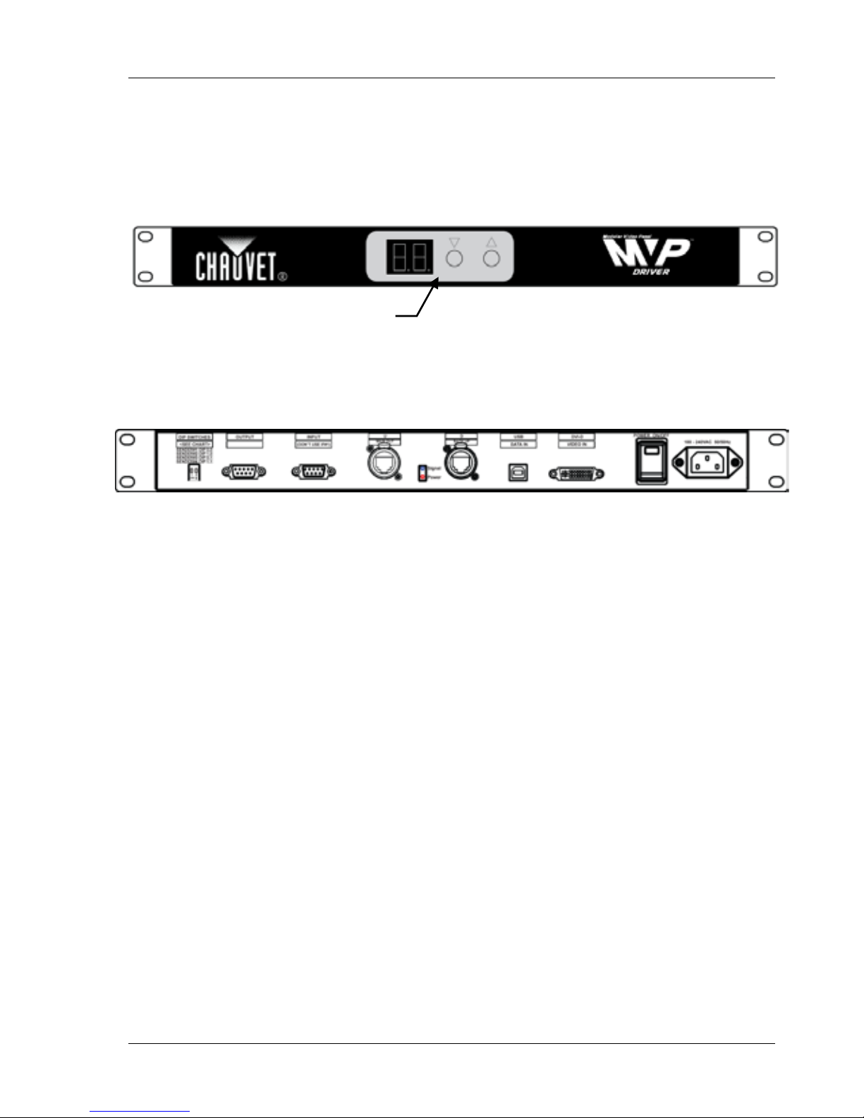
Not shown here are the rubber feet that can be attached t o the
MVP™ Driver to ensure proper rack mounting and space. These feet
are included with the Driver in separate packaging.
Front Panel
Back Panel
(refer to the Back Panel Connections section of this Guide for detailed information)
Brightness control
Page 6
MVP™ Driver QRG
Page 6 of 12
Product
Dimensions
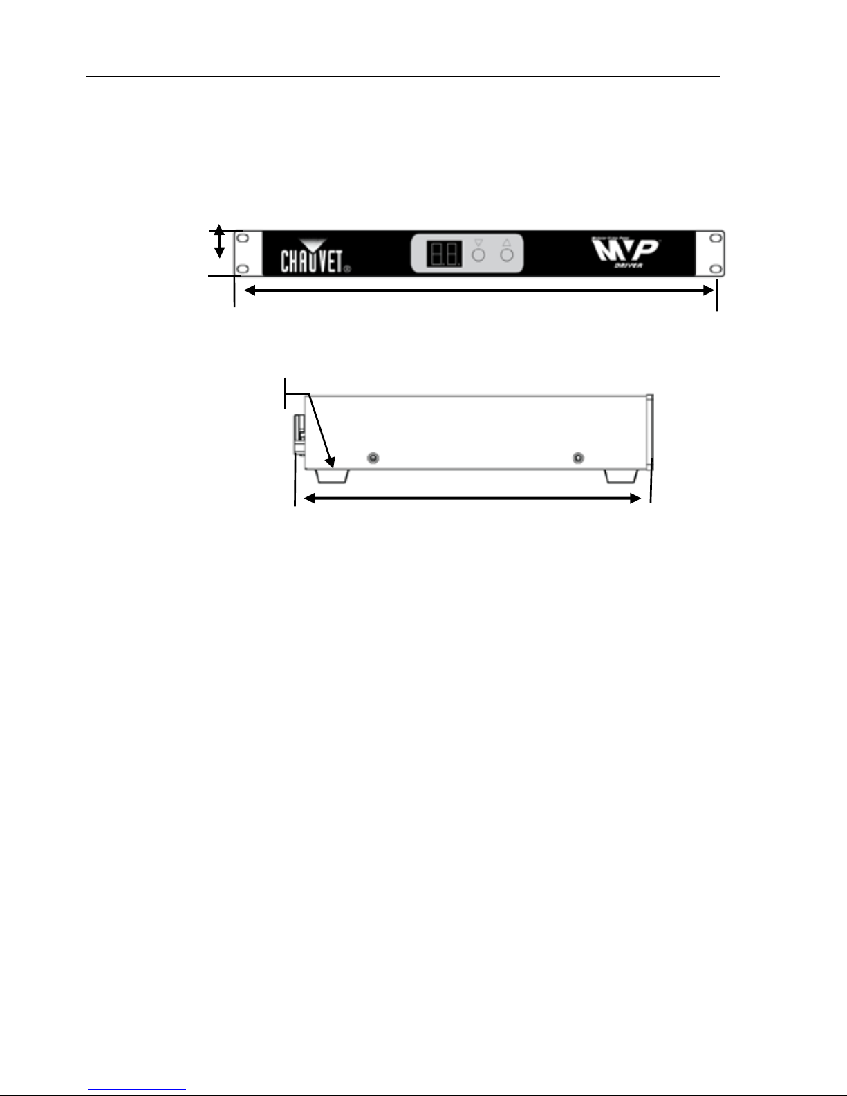
Dimensions: 9.06x 18.98 x 1.73 in (230 x 4 82 x 44 mm)
Front Panel
1.73 in
(44 mm)
18.98 in
(482 mm)
Side View
9.06 in
(230 mm)
Rubber feet attached
Page 7
MVP™ Driver QRG
Page 7 of 12
AC Power
This product has an auto-ran gi ng power supply that works with an
input voltage range of 100~2 40 VAC, 50/60 Hz.
Video
Input/Output
Video Source (Input): DVI-D
Video Output: etherCON® (2)
Display Refresh Rate: 2,000 Hz (flicker free)
Video Refresh Rate: 60 Hz
Mounting
Before mounting this produc t, read the Safety Notes at the beginning
of this Guide.
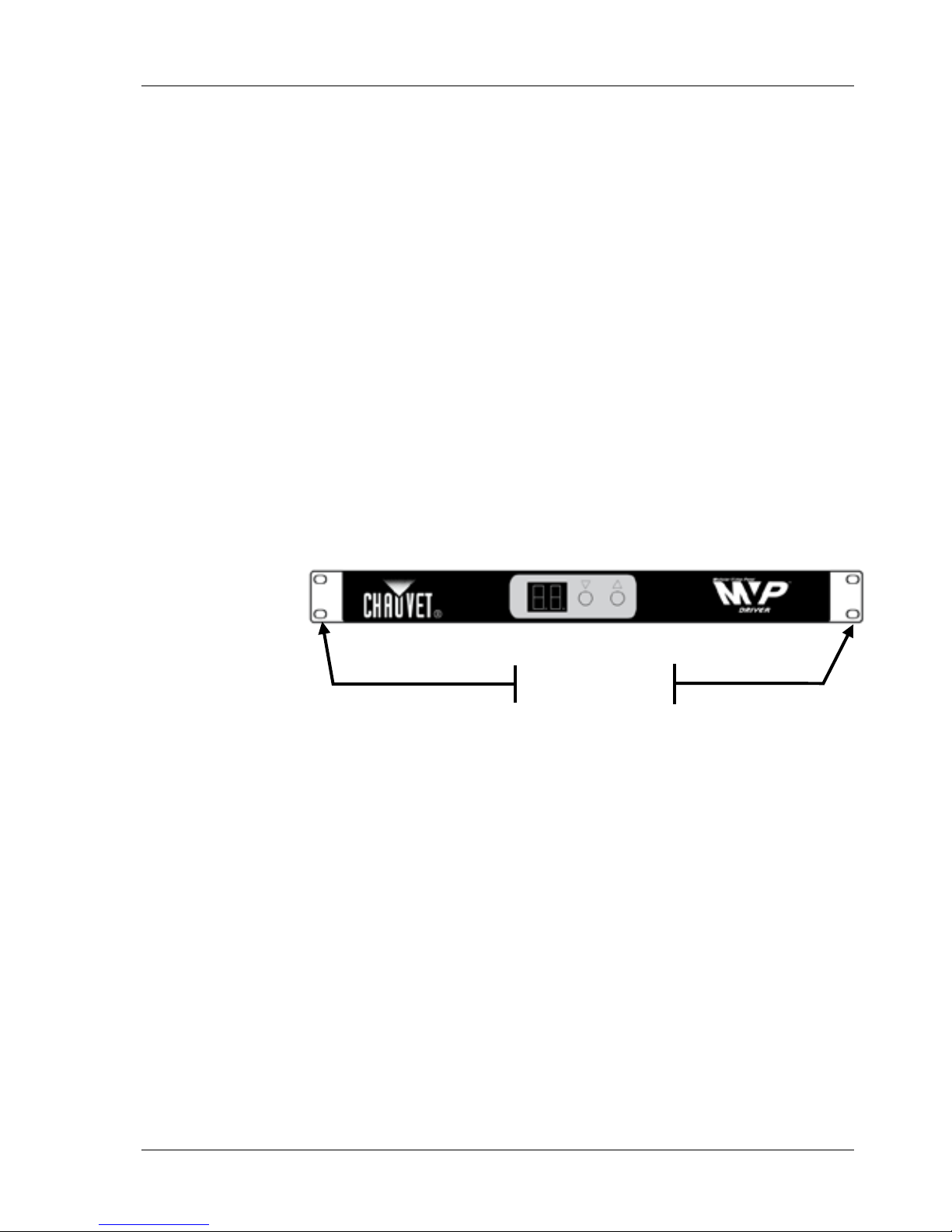
The MVP™ Driver can be rack mounted (2U) using t he mounting
ears on either side of the front panel. You can easily rack mount the
MVP™ Driver with the other MVP™ hardware components you are
using, if applicable, (i. e., MVP™ 526P Signal Processor, PC) for easy
setup and connection.
Product
Mounting
Diagram
Mounting Ears
Page 8
MVP™ Driver QRG
Page 8 of 12
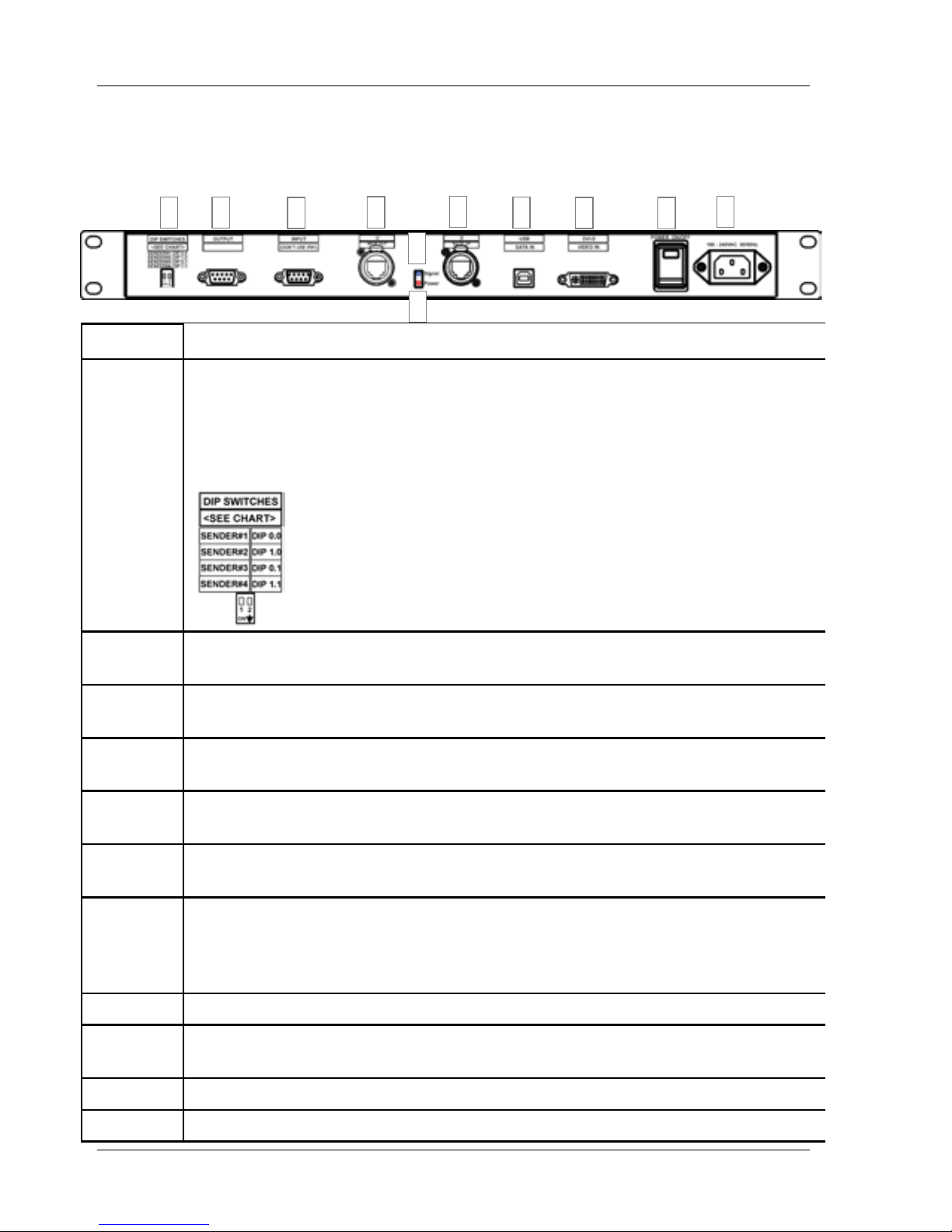
Back Panel
Connections
Disconnect power before connecting other equipment to the
MVP™ Driver.
Number Description
1
DIP SWITCHES addresser that can address up to 4 Drivers.
Up = Off; Down = On.
You will identify each Driver’s Sender address within the LED Studio
software application.
Note: The MVP™ Driver is the Sender, and the panels are the Receiver(s).
2
OUTPUT can be used to connect to the next MVP™ Driver. Use a 9-pin DSub serial cable for connection (not included).
3
INPUT (don’t use if #1) conn ection from the previous MVP™ Driver. Use
a 9-pin D-Sub serial cable for c onnection (not included).
4
U - MAIN OUT is the primary etherCON® signal output that connects to
the first MVP™ in a series.
5
Signal LED indicator flashes Green when the video connection s i gnal is
being received by the MVP™ Driver.
6
Power LED indicator display s R ed when power is being received by the
MVP™ Driver.
7
D - BACKUP is the secondary signal output and is pre-configured as a
backup that provides c om plete signal reproduction at 1024 X 512 pixels.
You can also configure both outputs to run separately providing a
resolution of up to 2048 x 640. This configuration eliminates the backup.
8
USB – DATA IN
connects to the content soft wa r e for addressing.
9
DVI-D – VIDEO IN connects to a video source. T he DVI signal must be a
direct digital signal in. You cannot use an analog to dig i tal adaptor.
10
Power On/Off
11 Plug 100 – 240 VAC 50/60 Hz
1
2
4
3
7
11
10
9
8
5
6
Page 9
MVP™ Driver QRG
Page 9 of 12
Calculating
the
Number
of Panels
per MVP™
Driver
The MVP™ Driver provides two signal output connections: U (Main)
and D (Backup). The number of panels will differ based on whether
you are using the U output as the Main and the D output as a backup,
or alternately using both outputs separately to incr ease the screen
resolution.
The default resolution for the MVP™ Video Wall is 1024 x 512. The
following provides the calculation and diagram f or determining the
number of panels that can be supported by one MVP™ Driver for
each scenario.
The MVP™ 18 will be used fo r each scenario. That panel has a pixel
ratio of 32 x 32.
Refer to the MVP™ Series (12, 18, 37.5) Getting Started for pixel and
other panel information.
Using U as
Main and
D as Backup
Using the pixel ratio of t he panel(s), calculate the num ber of panels
as follows.
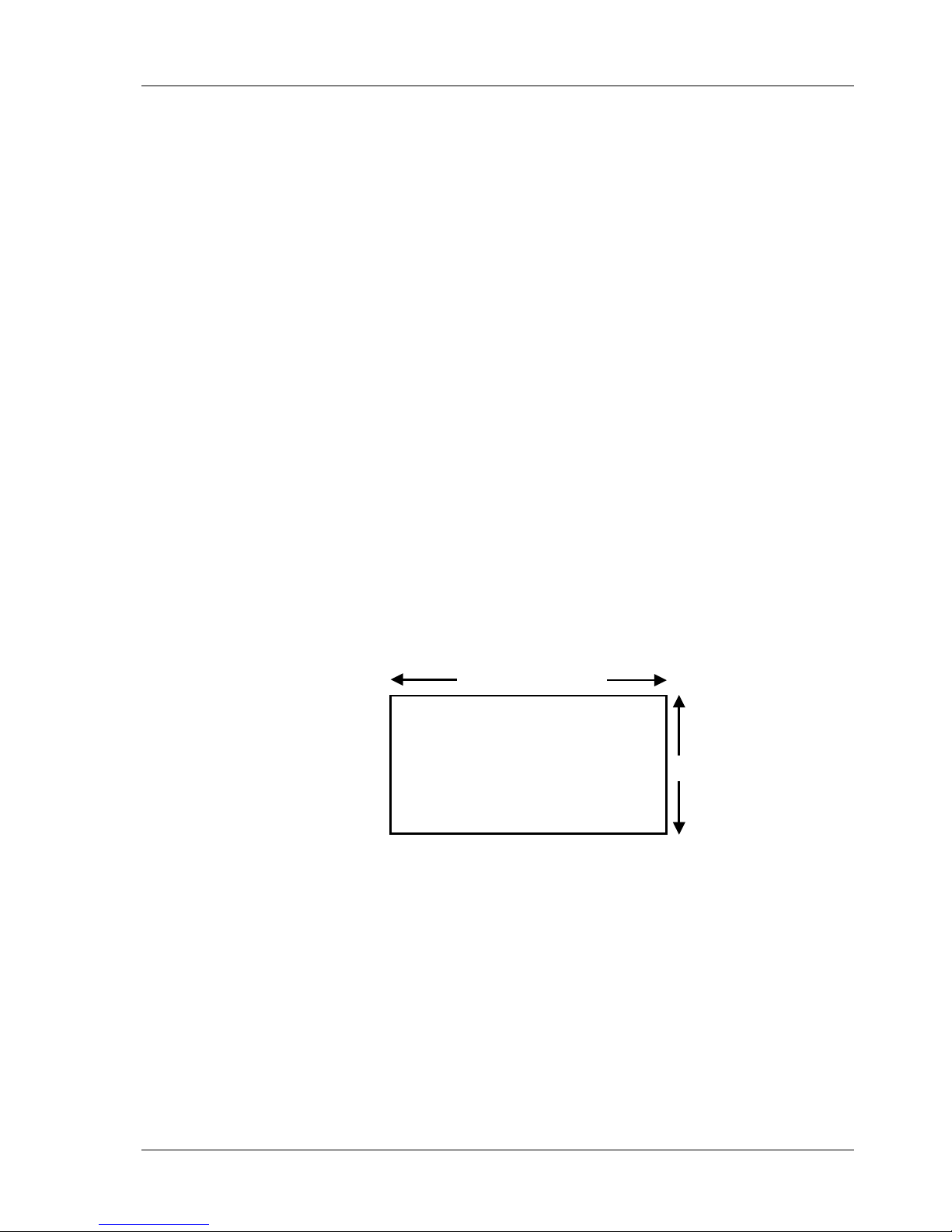
MVP 18 (32 x 32): 1024 / 32 = 32 panels
512 / 32 = 16 panels
The MVP™ Driver can support a video wall that is 32 x 16 panels, or
512 panels in total. Refer to the following example.
Video Wall using
MVP™ 18 panels
1024 = 32 panels
512 = 16 panels
Page 10
MVP™ Driver QRG
Page 10 of 12
Using Both
Signal
Outputs
to Increase
Screen
Resolution
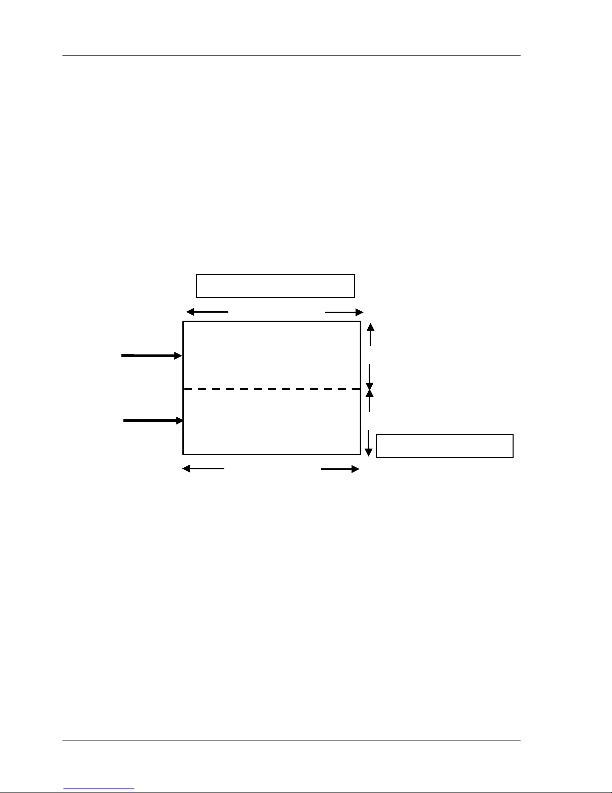
For a resolution of 2048 x 64 0 max. (doubling the 1024 and
increasing the 512 to 640) , using the pixel ratio of the panel,
calculate the number of pane ls as follows.
MPV™ 18 (32 x 32): 2048 / 32 = 64
640 / 32 = 20
Because you are using both out puts, one output will connect to
one half of your video wall and the other will connect t o the other
half. The result is two sections that are 32 panels x 10 panels
each, or 320 panels in total in each section. Refer to the
following example.
1024 = 32 panels
320 = 10 panels
1024 = 32 panels
32 (1/2) + 32 (1/2) = 64
320 = 10 panels
10 (1/2) + 10 (1/2) = 20
U (MAIN)
D
Page 11
MVP™ Driver QRG
Page 11 of 12
Manually
Adjusting
Brightness
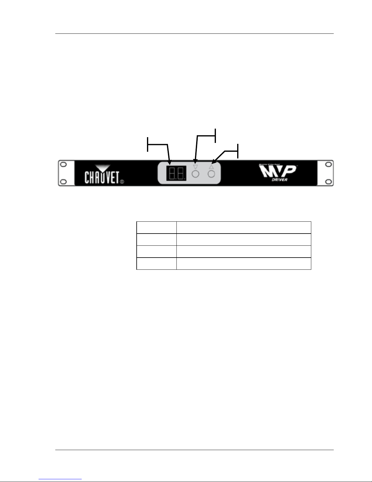
The front panel enables yo u to adjust the brightness of your video
panels. Initially, bri ghtness is defined in LED Studio. The
brightness default value range is 1 – 16. You can chang e the
brightness range in LED Studio, and manually adjust.
Use the Up and Down buttons on the front panel to manually
override the brightness sett ing defined in LED Studio. The
brightness value will display o n the LED table.
Refer to the LED Studio User Manaul for more information and
instructions.
The range of brightness vari ations that can be defined are:
Range
Description
1 – 16
Provides 16 brightness vari ations
1 - 32
Provides 32 brightness vari ations
1 – 64
Provides 64 brightness vari ations
Powering Up
the MVP™
Driver
This product supports AC from 100 to 240 VAC, 50-60 Hz. Once
plugged in, push the Power Switch on the bac k panel to ON.
Note: Make sure the power is turned off when connecting
equipment to the MVP™ Driver.
Down (less brightness)
Up (more brightness)
LED table
Page 12

MVP™ Driver QRG
Page 12 of 12
Contact Us
World Headquarters
CHAUVET®
General Information
Address: 5200 NW 108th Avenue
Sunrise, FL 33351
Voice: (954) 929-1115
Fax: (954) 929-5560
Toll free: (800) 762-1084
United Kingdom and Ireland
CHAUVET® Europe Ltd.
General Information
Address:
Unit 1C
Brookhill Road Industrial Estate
Pinxton, Nottingham, UK
NG16 6NT
Voice:
+44 (0)1773 511115
Fax: +44 (0)1773 511110
Technical Support
Technical Support
World Wide Web
www.chauvetlighting.com
World Wide Web
www.chauvetlighting.co.uk
Outside the US, United Kingdom, or Ireland, contact your distributor
of record. Follow their instr uc tions to request support or to return a
product. Visit our Web site for contact details.
MVP™ Driver QRG – Rev. 07
© Copyright 2011 CHAUVET®
All rights reserved
Printed in the P. R. C.
 Loading...