

Page 1

User Manual
Page 2

Edition
Notes
The Legend™ 41 2Z User Manual Rev. 1 covers the d escr iption, saf ety preca utio ns, insta llatio n,
released this
Trademarks
CHAUVET® is a registered trademark of CHAUVET & Sons Inc. (d/b/a CHAUVET® or
within this document are the property of their respective trademark holders.
Copyright Notice
CHAUVET® owns the content of this User Manual in its entirety, including but not limited to
Electronically published by CHAUVET® in the United States of America.
Manual Use
CHAUVET® authorizes its customers to download and print this manual for professional
sage, copy, storage,
ther purpose without
written consent from CHAUVET®.
Document
Printing
For better results, pr int this docum ent in c olor, on lett er size pap er (8.5 x 11 in) , doub le-sided. If
Intended
Any person in charge of ins talling, operating, an d/or m aintaining this product sh ould com pletely
operating, or maintaining this product.
Disclaimer
CHAUVET® bel ieves that the inform ation contained in this m anual is accurate in al l respects.
CHAUVET® may issue a revision of this manual or a new edition to incorporate such changes.
Document
Revision
The Legend™ 412Z User Manual Rev. 1 is the first edition of this manual. Go to
Author
Date
Editor
Date
D. Couppe
2/5/14
A. Leon
2/5/14
Edition Notes
programming, operation, and maintenance of the Legend™ 412Z. CHAUVET®
edition of the Legend™ 412Z User Manual in February 2014.
Chauvet). The CHAUVET® log o in its entirety including the CHAUVET ® name and the dotted
triangle, and all other trade marks in this manual pertaining to s ervices, products, or marketing
statements (exam ple: It’s Green Think ing™) are owned or l icensed by CHAUV ET®. Any other
product names, logos, bra nds, company names, and other trademark s featured or referred to
pictures, logos, trademarks, and resources.
© Copyright 2014 CHAUVET®. All rights reserved.
information purposes only. CHAUVET® expressly prohibits the u
distribution, modific ation, or printing of this manual or its c ontent for any o
using A4 paper (210 x 297 mm), configure your printer to scale the content accordingly.
Audience
read through the guide tha t shipped with the product, as well as this manual, before installing,
However, CHAU VET® assum es no responsibilit y for any errors or omissions in this document.
CHAUVET® reserves the right to revise and make chang es to the content of this document
without obligation th at CHAUVET ® notify any person or com pany of such rev ision or ch anges.
This does not in any way constitute a commitment by CHAUVET® to make such changes.
www.chauvetprofessional.com for the latest version.
Legend™ 412Z User Manual Rev. 1
Page 3

Table of Contents
Table of Contents
1. Before You Begin ...................................................................................................................................... 1
What Is Included ........................................................................................................................................................... 1
Claims .......................................................................................................................................................................................... 1
Manual Conventions .................................................................................................................................................................... 1
Symbols ....................................................................................................................................................................................... 1
Product At A Glance ..................................................................................................................................................... 2
Safety Notes ................................................................................................................................................................. 2
Personal Safety ............................................................................................................................................................................ 2
Mounting And Rigging .................................................................................................................................................................. 2
Power And Wiring ........................................................................................................................................................................ 2
Operation ..................................................................................................................................................................................... 2
Expected LED Lifespan ................................................................................................................................................ 2
2. Introduction ............................................................................................................................................... 3
Description .................................................................................................................................................................... 3
Features ........................................................................................................................................................................ 3
Overview ....................................................................................................................................................................... 4
Dimensions ................................................................................................................................................................... 5
3. Setup .......................................................................................................................................................... 6
AC Power ...................................................................................................................................................................... 6
AC Plug ........................................................................................................................................................................................ 6
Fuse Replacement ....................................................................................................................................................................... 6
Power Linking ............................................................................................................................................................... 6
DMX Linking.................................................................................................................................................................. 6
DMX Modes ................................................................................................................................................................................. 6
Mounting ....................................................................................................................................................................... 7
Orientation ................................................................................................................................................................................... 7
Rigging ......................................................................................................................................................................................... 7
Procedure .................................................................................................................................................................................... 7
4. Operation ................................................................................................................................................... 8
Control Panel Description ............................................................................................................................................. 8
Control Options ............................................................................................................................................................. 8
Programming ................................................................................................................................................................ 8
Menu Map ..................................................................................................................................................................... 8
Menu Map (Cont.) ......................................................................................................................................................... 9
Pan Inverse ................................................................................................................................................................................ 10
Tilt Inverse ................................................................................................................................................................................. 10
Back Light .................................................................................................................................................................................. 10
Fixture Time ............................................................................................................................................................................... 10
Software Version ........................................................................................................................................................................ 10
Temperature............................................................................................................................................................................... 10
Static Color (Manual Test) ........................................................................................................................................................ 10
Reset .......................................................................................................................................................................................... 10
White Calibration ........................................................................................................................................................................ 10
Auto Test .................................................................................................................................................................................... 11
Fan Mode ................................................................................................................................................................................... 11
DMX Personality ........................................................................................................................................................................ 11
DMX Control............................................................................................................................................................................... 11
DMX Values ................................................................................................................................................................ 12
DMX Values (cont.) ..................................................................................................................................................... 13
DMX Values (cont.) ..................................................................................................................................................... 14
Legend™ 412Z Quadrants for DMX Control .............................................................................................................................. 14
DMX Values (cont.) ..................................................................................................................................................... 15
Legend™ 412Z User Manual Rev. 1 -i-
Page 4

Table of Contents
DMX Values (cont.) ..................................................................................................................................................... 16
DMX Values (cont.) ..................................................................................................................................................... 17
DMX Values (cont.) ..................................................................................................................................................... 18
DMX Values (cont.) ..................................................................................................................................................... 19
5. Technical Information ............................................................................................................................. 20
Product Maintenance .................................................................................................................................................. 20
6. Technical Specifications ......................................................................................................................... 21
Returns ....................................................................................................................................................................... 22
Contact Us .................................................................................................................................................. 22
-ii- Legend™ 412Z User Manual Rev. 1
Page 5
1. BEFORE YOU BEGIN
What Is
• Legend™ 412Z
• Quick Reference Guide
Claims
Carefully unpack the pr oduct immediately and check the box to m ake sure all the parts are in
If the box or the contents (the product and included accessories) appear damaged from
ot related to shipping, or
concealed damage, file a claim with CHAUVET® within 7 days of delivery.
Manual
1–512
A range of values in the text
50/60
A set of mutually exclusive values in the text
<SET>
A button on the product’s control panel
Settings
A product function or a menu option
MENU>Settings
A sequence of menu options
1–10
A range of menu values from which to choose in a menu
Yes/No
A set of two mutually exclusive menu options in a menu
ON
A unique value to be entered or selected in a menu
Symbols
Symbols
Meaning
Critical installation, configuration, or operation information. Failure to
damage third-party equipment, or cause harm to the operator.
The term “DMX” used throughout this manual refers to the USITT DMX512-A digital data
transmission protocol.
Before You Begin
Included
Conventions
• Neutrik® powerCON® power cord
• Omega Bracket with mounting hardware
• Warranty Card
the package and are in good condition.
shipping or show signs of mishandling, notify the carr ier immediately, not CHAU VET®. Failure
to report damage to the c arrier im m ediatel y ma y inval idate your cl aim . In add ition , k eep the b ox
and contents for inspection.
For other issues, such as missing components or parts, damage n
Convention Meaning
comply with this information may cause the product not to work,
Important installation or configuration information. Failure to comply
with this information may keep the product from working.
Useful information.
Legend™ 412Z User Manual Rev. 1 -1-
Page 6
Product At A
x
x
x
Auto-Ranging Power
Supply
P
x
P
P
x
P
Safety Notes
Read all the following Safety Notes before working with this product. These notes include
important information about the installation, usage, and maintenance of this product.
This product contains no user-serviceable parts. Any reference to servicing in this
User Manual will only apply to properly trained CHAUVET® certified technicians. Do
not open the housing or attempt any repairs.
Personal Safety
• Avoid direct eye exposure to the light source while the product is on.
• Do not touch this product’s housing during operation because it may be very hot.
Mounting And
• This product is for indoor use only! To prevent risk of fire or shock, do not expose this
• When hanging this product, always secure to a fastening device using a safety cable.
Power And
• Always make sure you are connecting this product to the proper voltage in accordance
• Never disconnect this product by pulling or tugging on the power cable.
Operation
• Do not operate this product if you see damage on the housing, lenses, or cables. Have
• In case of a serious operating problem, stop using this product immediately!
In the unlikely event that your CHAUVET® product may require service, contact
CHAUVET® Technical Support.
Expected LED
LEDs gradually decline in br ightn ess over time, mostly because of heat. Packaged in clusters,
limiting the overall projection intensity may also help to extend the LEDs’ lifespan.
Before You Begin
Use on Dimmer
Glance
Rigging
Outdoor Use
Sound-Activated
DMX
Master/Slave
All applicable local codes and regulations apply to pro p er installation of this product.
• Always disconnect this product from its power source before servicing.
• Always connect this product to a grounded circuit to avoid the risk of electrocution.
product to rain or moisture.
• Mount this product in a location with adequate ventilation, at least 20 in (50 cm) from
adjacent surfaces.
• Make sure there are no flammable materials close to this product while it is operating.
• Do not carry this product from the head. Always use the base.
Auto Programs
Replaceable Fuse
User-Serviceable
Wiring
Lifespan
with the specifications in this manual or on the product’s specification label.
• Never connect this product to a dimmer pack or rheostat.
the damaged parts replaced by an authorized technician at once.
• Do not cover the ventilation slots when operating to avoid internal overheating.
• The maximum ambient temperature is 113 °F (45 °C). Do not operate this product at a
higher temperature.
LEDs exhibit higher operating temperatures than in ideal, single-LED conditions. For this
reason, using clustered L EDs at their fullest int ensity s ignificantl y reduces the LE Ds’ lifespan .
Under normal conditions, this lifespan can be 40,000 to 50,000 hours. If extending this
lifespan is vital, lower the operating temperature by improving the ventilation around the
product and reducing the ambient temperature to an optimal operating range. In addition,
-2- Legend™ 412Z User Manual Rev. 1
Page 7

2. INTRODUCTION
Description
Legend™ 412Z is a powerful and vers atile LED wash fixture with an outs tanding zoom range of
8° to 33°, making it perfect for a wide array of applications, from touring to broadcast. The
color RGBW emitters with four zones of
independent pixel mapping control, providing ultimate versatility in programming and use.
Features
• 15-, 27-, 31-, or 34-channel quad-color LED wash product
• Flicker-free operation for wide market application including broadcast and film
Legend™ 412Z features twelve 10-watt quad-
• Operating modes:
• 15-channel: 16-bit P/T control, P/T speed, RGBW, dimmer, strobe, color macro, macro
speed, zoom, reset
• 27-channel: 16-bit P/T control, P/T speed, RGBW quadrant control, dimmer, strobe,
color macro, macro speed, zoom, reset
• 31-channel: 16-bit P/T control, P/T speed, RGBW and dimmer quadrant control; strobe,
color macro, macro speed, zoom, reset
• 34-channel: 16-bit P/T control, P/T speed, RGBW, dimmer, and strobe quadrant control;
color macro, macro speed, zoom, reset
• 4 zones of LED control
• Fast and precise pan/tilt movement
• Versatile 8° to 33° zoom range
• 12 powerful 10-watt long-life quad-color RGBW LEDs
• Strobe macros with quadrant control
• Neutrik® powerCON® power input/output connections
• 3-pin and 5-pin DMX input/output connections
Introduction
Legend™ 412Z User Manual Rev. 1 -3-
Page 8
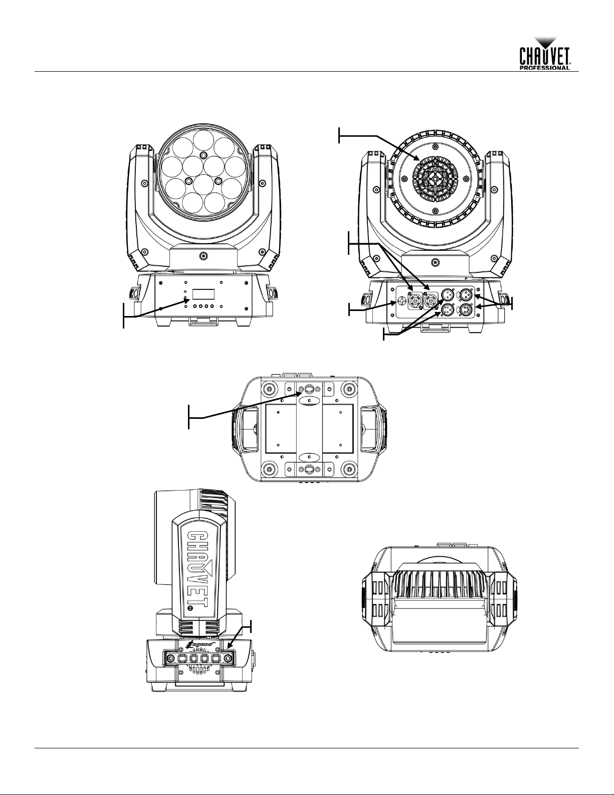
Power
In/Out
DMX Out
Front View
Rear View
Side View
Handle
Fan
Bottom View
Top View
Power
In/Out
DMX Out
DMX In DMX In
Control
Panel
Mounting
Bracket
Fuse
Introduction
Overview
-4- Legend™ 412Z User Manual Rev. 1
Page 9

Dimensions
13.98 in
355 mm
5.59 in
142 mm
6.37 in
171 mm
5.51 in
140 mm
7.21 in
183 mm
10.67 in
271 mm
12.5 in
318 mm
13.66 in
347 mm
10.2 in
259 mm
10.67 in
271 mm
Introduction
Legend™ 412Z User Manual Rev. 1 -5-
Page 10

AC Powe r
Each Lege nd™ 412Z has an auto-rang ing power sup ply that work s with an input voltag e range
,
chart
:
www.chauvetlighting.com/download/pro.
Always connect this product to a protected circuit with an appropriate electrical ground
to avoid the risk of electrocution or fire.
Never connect this product to a rheostat (variable resistor) or dimmer circuit, even if the
rheostat or dimmer channel serves onl y as a 0 to 100% switch.
AC Plug
The Legend™ 412Z comes with a Neutr ik® powerC ON A conn ector on one e nd and a n Edison
no plug or you need to change the Edison plug, use the table below to wire the new plug..
Connection
Wire (U.S.)
Wire (Europe)
Screw Color
AC Live
Black
Brown
Yellow or Brass
AC Neutral
White
Blue
Silver
AC Ground
Green/Yellow
Green/Yellow
Green
Fuse
1. Disconnect this product from the power outlet.
4. Screw the fuse holder cap back in place and reconnect power.
Make sure to disconnect the product’s power cord before replacing a blown fuse. Always
replace the blown fuse with another of the same type and rating.
Power Linking
The Legend™ 412Z suppor ts power linking. You can power link up to 9 pr oducts a t 120 V; u p to
Power linking cables are available from
CHAUVET® for purchase.
DMX Linking
You can link the Legend™ 412Z to a D MX contr oller using a stand ard DMX seria l connectio n. If
using other DMX compatible products with the Legend™ 412Z, you can control each
individually with a single DMX controller.
DMX Modes
The Legend™ 412Z uses the standard DMX data connection for the 15-, 27-, 31-, and
• The DMX Values section provides you with detailed information regarding the DMX modes.
Setup
3. SETUP
of 100 to 240 VAC, 50/60 H z. To determine the power requirements for each Legend™ 412Z
refer to the label affixed to the prod uct. You can also r efer to the T echnical Specif ications
in this manual.
The listed current r ati ng in d icates t he maximum current dr a w dur ing normal operation . For more
information, you may download Sizing Circuit Breakers from the CHAUVET® website
plug on the other end (U S market). If the po wer cord adapter th at came with your pr oduct has
Replacement
2. Using a Phillips #2 head screwdriver, unscrew the fuse holder cap from the housing.
3. Remove the blown fuse and replace with another fuse of the same type and rating
(T 6.3 A, 250 V).
15 at 208 V; or up to 17 at 230 V.
This product comes with a power input cord.
34-channel DMX modes.
• Refer to the Introduction chapter for a brief description of these modes.
• Refer to the Operation chapter to learn how to configure the Legend™ 412Z to work in
these modes.
-6- Legend™ 412Z User Manual Rev. 1
Page 11

Mounting
Before mounting this product, read and follow the Safety Notes. For our CHAUVET® line of
mounting clamps, go to http://trusst.com/productcategory/base-plates-accessories-clamps/.
Orientation
Always mount this product in a safe position and make sure there is adequate room for
Rigging
CHAUVET® recommends using the following general guidelines when mounting this product.
• When selecting an installation location, consider easy access to this product for operation,
as CH-05 from CHAUVET®).
Procedure
The Legend™ 41 2Z comes with a double-yoke bracket to which you can either a ttac h m ounting
of this product. Use at least one mounting point per product.
When using only one mounting clamp with this fixture, you must use a clamp with a
captive bolt to prevent accidental loosening.
Floor Mounting
Overhead Mounting
Mounting Clamps
Safety Cable
Omega Brackets
Setup
ventilation, configuration, and maintenance.
programming adjustments, and routine maintenance.
• Make sure to mount this product away from any flammable material as indicated in the
Safety Notes
• Never mount in places where rain, high humidity, extreme temperature changes, or
restricted ventilation may affect the product.
• If hanging this product, make sure that the mounting location can support the product’s
weight. See the T ec hnical Specif ic at io ns
product.
• When hanging this product, always secure to a fastening device using a safety cable (such
clamps for hanging or s impl y use as a f loor stan d. You m ust suppl y your o wn mountin g clam ps.
Make sure the clamps (such as CLP-15 from CHAUVET®) are c apable of supporting the weight
.
for the weight-bearing requirements of this
Mounting Diagram
Legend™ 412Z User Manual Rev. 1 -7-
Page 12

Control Panel
Button
Function
<MENU>
Exits from the current menu or function
<ENTER>
Enables the currently displayed menu or sets the currently
selected value in to the current function
<UP>
Navigates upward through the menu list and increases the
numeric value when in a function
<DOWN>
Navigates downward through the menu list and decreases the
numeric value when in a function
Control Options
You can set the Legend™ 412Z starting address in the 001–512 DMX range. This
enables control of up to 15 products in the 34-channel 34chan personality.
Programming
Refer to the Menu Map to understand the menu opt ions. The menu m ap shows the m ain
Press <MENU> repeatedly to exit to the previous main level.
Main Level
Programming Levels
Description
DMX Address
001–512
Selects the DMX starting address
15chan
Selects 15–channel DMX personality
27chan
Selects 27–channel DMX personality
31chan
Selects 31–channel DMX personality
34chan
Selects 34–channel DMX personality
Yes
No
Yes
No
On
Display backlight alwa ys on
Off
Display backlight turns off after 1 min.
Red
Green
Blue
Operation
4. OPERATION
Description
level and a variable number of programming levels for each option.
• To go to the desired main level, press <MENU> repeatedly until the option shows on
the display. Press <ENTER> to select. This will take you to the first programming
level for that option.
• To select an option or value within the current programming level, press <UP> or
<DOWN> until the option shows on the display. Press <ENTER> to select. In this
case, if there is another programming level, you will see that first option, or you will
see the selected value.
•
Menu Map
Channel Mode
Pan Inverse
Tilt Inverse
Back Light
White Balance
125–255
Defines the direction of the pan function
Defines the direction of the tilt function
Defines the color temperature when the red,
green, and blue faders are set at 100%
-8- Legend™ 412Z User Manual Rev. 1
Page 13

Menu Map (Cont.)
Pan
Sets Pan 0–540°
Tilt
Sets Tilt 0–270°
Red1
Sets Quadrant 1 red LED intensity
Green1
Sets Quadrant 1 green LED intensity
Blue1
Sets Quadrant 1 blue LED intensity
White1
Sets Quadrant 1 white LED intensity
Red2
Sets Quadrant 2 red LED intensity
Green2
Sets Quadrant 2 green LED intensity
Blue2
Sets Quadrant 2 blue LED intensity
White2
Sets Quadrant 2 white LED intensity
Red3
Sets Quadrant 3 red LED intensity
Green3
Sets Quadrant 3 green LED intensity
Blue3
Sets Quadrant 3 blue LED intensity
White3
Sets Quadrant 3 white LED intensity
Red4
Sets Quadrant 4 red LED intensity
Green4
Sets Quadrant 4 green LED intensity
Blue4
Sets Quadrant 4 blue LED intensity
White4
Sets Quadrant 4 white LED intensity
Zoom
Sets zoom position
Dimmer
Sets dimmer value
Strobe
Selects the strobe frequency (0–20 Hz)
Auto Test
Starts the product’s test sequence
Temp.
Shows the product’s current temperature (°C)
Low
High
Auto
Shows the total amount of time the product has
been used (hours)
Shows the version of the software that has been
installed
Reset
Resets product to its home setting
Main Level Programming Levels Description
Operation
Manual Test
Fan Mode
000–255
Selects the fan’s op erati on mode.
Fixture Time
Firmware Version
Legend™ 412Z User Manual Rev. 1 -9-
Page 14

Pan Inverse
This setting allows the user to invert the direction of the pan control.
2. Select Yes or No.
Tilt Inverse
This setting allows the user to invert the direction of the pan control.
2. Select Yes or No.
Back Light
This setting determines whether the c ontro l pan el d is p lay backlight sta ys on in def i nite ly or turns
2. Select Yes or No.
Fixture Time
This option shows the amount of hours the Legend™ 412Z has been in use throughout its
• Go to the Fixture Time main level.
Software Version
This option shows the user the software version currently installed in the Legend™ 412Z.
• Go to the Firmware Version main level.
Temperature
This setting allows the user to view the internal temperature (C°) of the Legend™ 412Z.
• Go to the Temp. main level.
Static Color
The Static Color mode al lows for permanent positioning, str obing, dimming, and RGBW color
• Select the strobe value (000–255).
Reset
This setting allows you to reset the L egend™ 412Z to the default values , including th e custom
2. Wait for the reset process to finish.
White Calibration
This setting allows you to select the white c olor shown by the Leg end™ 412Z when the DMX
4. Repeat for the other colors.
When selecting White B alance, you w ill only be able to define the values of Red, Green,
or Blue.
will define the color
temperature shown when the RGB faders are set to 255.
Operation
1. Go to the Pan Inverse main level.
1. Go to the Tilt Inverse main level.
off after 1 minutes of inactivity.
1. Go to the Back Light main level.
lifetime.
(Manual Test)
mixing without a DMX controller.
1. Go to the Manual Test main level.
2. Select the desired position (Pan or Tilt).
a. Select the position value (000–255).
b. Repeat for the other position.
3. Select the desired color (Red 1–4, Green 1–4, Blue 1–4, or White 1–4).
a. Select the color value (000–255).
b. Repeat for the other colors.
4. Select the beam angle (Zoom).
• Select the angle value (000–255).
5. Select the intensity (Dimmer).
• Select the intensity value (000–255).
6. Select the strobe frequency from 0–20 Hz (Strobe).
programs.
1. Go to the Reset main level.
controller’s red, green, and blue faders are set to 255.
1. Go to the White Balance main level.
2. Select a color (Red, Green, or Blue).
3. Select a color value (125–255).
-10- Legend™ 412Z User Manual Rev. 1
The values of Red, Green, or Blue configured from White B alance
Page 15

Operation
Auto Test
This setting starts the products test sequence.
Go to the Auto Test main level.
Fan Mode
This setting allows you to control the fan speed.
2. Select the desired speed (Low, High, or Auto).
• When in AUTO, the fan speed automatically changes so the product’s temperature
rises above a certain level.
DMX Personality
This setting allows you to choose a particular DMX personality.
2. Select the desired personality (15chan, 27chan, 31chan, or 34chan).
• See the DMX Values section for the highest starting address you can select for each
the new personality setting.
DMX Control
In this mode, each product will respond to a unique starting address from the DMX controller. All
b. Select the starting address (001–512).
The highest recommended starting address for each DMX mode is as follows:
15chan
498
31chan
482
27chan
486
34chan
479
•
1. Go to the Fan Mode main level.
does not exceed the maximum allowed value.
• When in the other settings, the fan speed follows the predefined values.
• The internal controller will over ride any manual setting if the internal temperature
1. Go to the Channel Mode main level.
personality.
• Make sure that the starting addresses on the various products do not overlap due to
products with the same starting address will respond in unison.
1. Select a DMX personality as shown in DMX Personality.
2. Set the starting address:
a. Go to the DMX Address main level.
DMX Personality DMX Address DMX Personality DM X Addres s
Legend™ 412Z User Manual Rev. 1 -11-
Page 16

15chan
1
Pan
000 ó 255
0–540°
2
Fine Pan
000 ó 255
Fine control of panning
3
Tilt
000 ó 255
0–270°
4
Fine Tilt
000 ó 255
Fine control of tilting
5
P/T Speed
000 ó 255
Pan/Tilt speed (fast to slow)
6
Dimmer
000 ó 255
0–100%
000 ó 019
220 ó 255
No function
No function
8
Red
000 ó 255
0–100%
9
Green
000 ó 255
0–100%
10
Blue
000 ó 255
0–100%
11
White
000 ó 255
0–100%
Operation
DMX Values
Channel Function Value Percent/Setting
7 Strobe
020 ó 039
040 ó 059
060 ó 079
080 ó 099
100 ó 119
120 ó 139
140 ó 159
160 ó 179
180 ó 199
200 ó 219
0–20 Hz
Strobe Macro 1
Strobe Macro 2
Strobe Macro 3
Strobe Macro 4
Strobe Macro 5
Strobe Macro 6
Strobe Macro 7
Strobe Macro 8
Strobe Macro 9
-12- Legend™ 412Z User Manual Rev. 1
Page 17

DMX Values (cont.)
15chan
000 ó 019
240 ó 255
No function
Macro 23
13
Macro Speed
000 ó 255
0–100%
14
Zoom
000 ó 255
0–100%
000 ó 007
206 ó 255
No function
No function
Channel Function Value Percent/Setting
(cont.)
12 Color Macro
020 ó 029
030 ó 039
040 ó 049
050 ó 059
060 ó 069
070 ó 079
080 ó 089
090 ó 099
100 ó 109
110 ó 119
120 ó 129
130 ó 139
140 ó 149
150 ó 159
160 ó 169
170 ó 179
180 ó 189
190 ó 199
200 ó 209
210 ó 219
220 ó 229
230 ó 239
Operation
Macro 1
Macro 2
Macro 3
Macro 4
Macro 5
Macro 6
Macro 7
Macro 8
Macro 9
Macro 10
Macro 11
Macro 12
Macro 13
Macro 14
Macro 15
Macro 16
Macro 17
Macro 18
Macro 19
Macro 20
Macro 21
Macro 22
Legend™ 412Z User Manual Rev. 1 -13-
15 Reset
008 ó 069
070 ó 129
130 ó 190
191 ó 205
Reset pan/tilt
Reset all
Pan/tilt movement blackout
Zoom presets
Page 18

27chan
1
Pan
000 ó 255
0–540°
2
Fine Pan
000 ó 255
Fine control of panning
3
Tilt
000 ó 255
0–270°
4
Fine Tilt
000 ó 255
Fine control of tilting
5
P/T Speed
000 ó 255
Pan/Tilt speed (fast to slow)
6
Dimmer
000 ó 255
0–100%
000 ó 019
220 ó 255
No function
No function
8
Red Quadrant 1
000 ó 255
0–100%
9
Green Quadrant 1
000 ó 255
0–100%
10
Blue Quadrant 1
000 ó 255
0–100%
11
White Quadrant 1
000 ó 255
0–100%
12
Red Quadrant 2
000 ó 255
0–100%
13
Green Quadrant 2
000 ó 255
0–100%
14
Blue Quadrant 2
000 ó 255
0–100%
15
White Quadrant 2
000 ó 255
0–100%
16
Red Quadrant 3
000 ó 255
0–100%
17
Green Quadrant 3
000 ó 255
0–100%
18
Blue Quadrant 3
000 ó 255
0–100%
19
White Quadrant 3
000 ó 255
0–100%
20
Red Quadrant 4
000 ó 255
0–100%
21
Green Quadrant 4
000 ó 255
0–100%
22
Blue Quadrant 4
000 ó 255
0–100%
23
White Quadrant 4
000 ó 255
0–100%
Legend™ 412Z
Quadrants for
Operation
DMX Values (cont.)
Channel Function Value Percent/Setting
7 Strobe
020 ó 039
040 ó 059
060 ó 079
080 ó 099
100 ó 119
120 ó 139
140 ó 159
160 ó 179
180 ó 199
200 ó 219
0–20 Hz
Strobe Macro 1
Strobe Macro 2
Strobe Macro 3
Strobe Macro 4
Strobe Macro 5
Strobe Macro 6
Strobe Macro 7
Strobe Macro 8
Strobe Macro 9
DMX Control
-14- Legend™ 412Z User Manual Rev. 1
Page 19

DMX Values (cont.)
27chan
000 ó 019
240 ó 255
No function
Macro 23
25
Macro Speed
000 ó 255
0–100%
26
Zoom
000 ó 255
0–100%
000 ó 007
206 ó 255
No function
No function
Channel Function Value Percent/Setting
(cont.)
24 Color Macro
020 ó 029
030 ó 039
040 ó 049
050 ó 059
060 ó 069
070 ó 079
080 ó 089
090 ó 099
100 ó 109
110 ó 119
120 ó 129
130 ó 139
140 ó 149
150 ó 159
160 ó 169
170 ó 179
180 ó 189
190 ó 199
200 ó 209
210 ó 219
220 ó 229
230 ó 239
Operation
Macro 1
Macro 2
Macro 3
Macro 4
Macro 5
Macro 6
Macro 7
Macro 8
Macro 9
Macro 10
Macro 11
Macro 12
Macro 13
Macro 14
Macro 15
Macro 16
Macro 17
Macro 18
Macro 19
Macro 20
Macro 21
Macro 22
Legend™ 412Z User Manual Rev. 1 -15-
27 Reset
008 ó 069
070 ó 129
130 ó 190
191 ó 205
Reset pan/tilt
Reset all
Pan/tilt movement blackout
Zoom presets
Page 20

31chan
1
Pan
000 ó 255
0–540°
2
Fine Pan
000 ó 255
Fine control of panning
3
Tilt
000 ó 255
0–270°
4
Fine Tilt
000 ó 255
Fine control of tilting
5
P/T Speed
000 ó 255
Pan/Tilt speed (fast to slow)
6
Dimmer
000 ó 255
0–100%
000 ó 019
220 ó 255
No function
No function
8
Red Quadrant 1
000 ó 255
0–100%
9
Green Quadrant 1
000 ó 255
0–100%
10
Blue Quadrant 1
000 ó 255
0–100%
11
White Quadrant 1
000 ó 255
0–100%
12
Dimmer Quadrant 1
000 ó 255
0–100%
13
Red Quadrant 2
000 ó 255
0–100%
14
Green Quadrant 2
000 ó 255
0–100%
15
Blue Quadrant 2
000 ó 255
0–100%
16
White Quadrant 2
000 ó 255
0–100%
17
Dimmer Quadrant 2
000 ó 255
0–100%
18
Red Quadrant 3
000 ó 255
0–100%
19
Green Quadrant 3
000 ó 255
0–100%
20
Blue Quadrant 3
000 ó 255
0–100%
21
White Quadrant 3
000 ó 255
0–100%
22
Dimmer Quadrant 3
000 ó 255
0–100%
23
Red Quadrant 4
000 ó 255
0–100%
24
Green Quadrant 4
000 ó 255
0–100%
25
Blue Quadrant 4
000 ó 255
0–100%
26
White Quadrant 4
000 ó 255
0–100%
27
Dimmer Quadrant 4
000 ó 255
0–100%
Operation
DMX Values (cont.)
Channel Function Value Percent/Setting
7 Strobe
020 ó 039
040 ó 059
060 ó 079
080 ó 099
100 ó 119
120 ó 139
140 ó 159
160 ó 179
180 ó 199
200 ó 219
0–20 Hz
Strobe Macro 1
Strobe Macro 2
Strobe Macro 3
Strobe Macro 4
Strobe Macro 5
Strobe Macro 6
Strobe Macro 7
Strobe Macro 8
Strobe Macro 9
-16- Legend™ 412Z User Manual Rev. 1
Page 21

DMX Values (cont.)
31chan
000 ó 019
240 ó 255
No function
Macro 23
29
Macro Speed
000 ó 255
0–100%
30
Zoom
000 ó 255
0–100%
000 ó 007
206 ó 255
No function
No function
Channel Function Value Percent/Setting
(cont.)
28 Color Macro
020 ó 029
030 ó 039
040 ó 049
050 ó 059
060 ó 069
070 ó 079
080 ó 089
090 ó 099
100 ó 109
110 ó 119
120 ó 129
130 ó 139
140 ó 149
150 ó 159
160 ó 169
170 ó 179
180 ó 189
190 ó 199
200 ó 209
210 ó 219
220 ó 229
230 ó 239
Operation
Macro 1
Macro 2
Macro 3
Macro 4
Macro 5
Macro 6
Macro 7
Macro 8
Macro 9
Macro 10
Macro 11
Macro 12
Macro 13
Macro 14
Macro 15
Macro 16
Macro 17
Macro 18
Macro 19
Macro 20
Macro 21
Macro 22
Legend™ 412Z User Manual Rev. 1 -17-
31 Reset
008 ó 069
070 ó 129
130 ó 190
191 ó 205
Reset pan/tilt
Reset all
Pan/tilt movement blackout
Zoom presets
Page 22

34chan
1
Pan
000 ó 255
0–540°
2
Fine Pan
000 ó 255
Fine control of panning
3
Tilt
000 ó 255
0–270°
4
Fine Tilt
000 ó 255
Fine control of tilting
5
P/T Speed
000 ó 255
Pan/Tilt speed (fast to slow)
6
Dimmer
000 ó 255
0–100%
7
Red Quadrant 1
000 ó 255
0–100%
8
Green Quadrant 1
000 ó 255
0–100%
9
Blue Quadrant 1
000 ó 255
0–100%
10
White Quadrant 1
000 ó 255
0–100%
11
Dimmer Quadrant 1
000 ó 255
0–100%
000 ó 019
250 ó 255
No function
No function
13
Red Quadrant 2
000 ó 255
0–100%
14
Green Quadrant 2
000 ó 255
0–100%
15
Blue Quadrant 2
000 ó 255
0–100%
16
White Quadrant 2
000 ó 255
0–100%
17
Dimmer Quadrant 2
000 ó 255
0–100%
000 ó 019
250 ó 255
No function
No function
19
Red Quadrant 3
000 ó 255
0–100%
20
Green Quadrant 3
000 ó 255
0–100%
21
Blue Quadrant 3
000 ó 255
0–100%
22
White Quadrant 3
000 ó 255
0–100%
23
Dimmer Quadrant 3
000 ó 255
0–100%
000 ó 019
250 ó 255
No function
No function
25
Red Quadrant 4
000 ó 255
0–100%
26
Green Quadrant 4
000 ó 255
0–100%
27
Blue Quadrant 4
000 ó 255
0–100%
28
White Quadrant 4
000 ó 255
0–100%
29
Dimmer Quadrant 4
000 ó 255
0–100%
000 ó 019
250 ó 255
No function
No function
Operation
DMX Values (cont.)
Channel Function Value Percent/Setting
12 Strobe Quadrant 1
18 Strobe Quadrant 2
24 Strobe Quadrant 3
020 ó 249
020 ó 249
020 ó 249
0–20 Hz
0–20 Hz
0–20 Hz
-18- Legend™ 412Z User Manual Rev. 1
30 Strobe Quadrant 4
020 ó 249
0–20 Hz
Page 23

DMX Values (cont.)
34chan
000 ó 019
240 ó 255
No function
Macro 23
32
Macro Speed
000 ó 255
0–100%
33
Zoom
000 ó 255
0–100%
000 ó 007
206 ó 255
No function
No function
Channel Function Value Percent/Setting
(cont.)
31 Color Macro
020 ó 029
030 ó 039
040 ó 049
050 ó 059
060 ó 069
070 ó 079
080 ó 089
090 ó 099
100 ó 109
110 ó 119
120 ó 129
130 ó 139
140 ó 149
150 ó 159
160 ó 169
170 ó 179
180 ó 189
190 ó 199
200 ó 209
210 ó 219
220 ó 229
230 ó 239
Operation
Macro 1
Macro 2
Macro 3
Macro 4
Macro 5
Macro 6
Macro 7
Macro 8
Macro 9
Macro 10
Macro 11
Macro 12
Macro 13
Macro 14
Macro 15
Macro 16
Macro 17
Macro 18
Macro 19
Macro 20
Macro 21
Macro 22
Legend™ 412Z User Manual Rev. 1 -19-
34 Reset
008 ó 069
070 ó 129
130 ó 190
191 ó 205
Reset pan/tilt
Reset all
Pan/tilt movement blackout
Zoom presets
Page 24

Product
To maintain optimum performance and minimize wear, you should clean this product
up reduces light out put
• Gently polish the lens surfaces until they are free of haze and lint.
Technical Information
5. TECHNICAL INFORMATION
Maintenance
frequently. Usage an d environment are contributing fac tors in determining the cleaning
frequency.
As a rule, clean this product at least twice a month. Dust buildperformance and can c ause overheating. This c an lead to reduced light s ource life and
increased mechanical wear.
To clean your product:
• Unplug the product from power.
• Wait until the product is at room temperature.
• Use a vacuum (or dry compressed air) and a soft brush to remove dust collected on
the external vents.
• Clean all external surfaces with a mild solution of non-ammonia glass cleaner or
isopropyl alcohol.
• Apply the solution directly to a soft, lint-free cotton cloth or a lens cleaning tissue.
• Wipe any dirt or grime to the outside edges of the lens surface.
Always dry the external surfaces thoroughly and carefully after cleaning them.
Do not spin the cooling fans while blowing compressed air into them.
-20- Legend™ 412Z User Manual Rev. 1
Page 25

6. TECHNICAL SPECIFICATIONS
Dimensions and
7.21 in (183 mm)
10.67 in (271 mm)
13.98 in (355 mm)
16.6 lb (7.5 kg)
Note: Dimensions in inches rounded to the nearest decimal digit.
Power
Switching (internal)
100–240 VAC, 50/60 Hz
Auto-ranging
Consumption
185 W
188 W
Current
1.5 A
0.8 A
Power linking current
(products)
13.6 A (9 products)
13.6 A (17 products)
Fuse/Breaker
T 6.3 A, 250 V
T 6.3 A, 250 V
Power I/O
U.S./Canada
Worldwide
Power input connector
Neutrik® powerCON® A
Neutrik® powerCON® A
Power output connector
Neutrik® powerCON® B
Neutrik® powerCON® B
Power cord plug
Bare-wired
Bare-wired
Light Source
LED
10 W
50,000 hours
Quad-color (RGBW)
12
2.9 A
Photo Optic
Parameter
Standard Optics
Illuminance (8°) @ 5 m
3,880 lux
Illuminance (33°) @ 5 m
330 lux
Beam angle
8° to 33°
Field angle
11° to 53°
Strobe rate
0–20 Hz
Thermal
113 °F (45 °C)
Fan-Assisted Convection
DMX
3- and 5-pin XLR
Sockets
15, 27, 31 or 34
Ordering
Product Name
Item Code
UPC Number
Legend™ 412Z
06010780
781462211288
Technical Information
Weight
Length Width Height Weight
Power Supply Type Range Voltage Selection
Parameter 120 VAC, 60 Hz 230 VAC, 50 Hz
Type Power Lifespan
Color Quantity Current
Max. External Temperature Cooling System
I/O Connectors Connector Type Channel Range
Legend™ 412Z User Manual Rev. 1 -21-
Page 26

Returns
You must send the product prepaid, in the or iginal box , and with the origi nal pack ing and
and a
will refuse any product
returned without an RMA number.
DO NOT write the RMA number directly on the box. Instead, write it on a p roperly
affixed label.
Once you have received the RMA number, include the following information on a piece of
are
recommended.
CHAUVET® reserves the right to use its own discretion to repair or replace
returned product(s).
WORLD HEADQUARTERS - CHAUVET®
General Information
Technical Support
www.chauvetlighting.com
UNITED KINGDOM AND IRELAND - CHAUVET® Europe Ltd.
General Information
Fax: +44 (0)1773 511110
Technical Support
MEXICO - CHAUVET® Mexico
General Information
Voice: +52 (728) 285-5000
Technical Support
www.chauvet.com.mx
Outside the U.S., United Kingdom, Ireland, or Mexico, contact your dealer. Follow their instructions to
request support or to return a product. Visit our website for contact details.
accessories. CHAUVET® will not issue call tags.
Call CHAUVET ® and request a Retur n M erchand ise Authori zation ( RMA) num ber befor e
shipping the product. Be prepared to provide the model number, serial number,
brief description of the cause(s) for the return.
Clearly label the package with an RMA number. CHAUVET®
paper inside the box:
• Your name
• Your address
• Your phone number
• The RMA number
• A brief description of the problem(s)
Be sure to pack the product properly. Any shipping damage resulting from inadequate
packaging will be the customer’s responsibility. FedEx packing or double-boxing
CONTACT
S
U
Address:5200 NW 108th Avenue
Sunrise, FL 33351
Voice: (954) 577-4455
Fax: (954) 929-5560
Toll free: (800) 762-1084
Address:Unit 1C
Brookhill Road Industrial Estate
Pinxton, Nottingham, UK
NG16 6NT
Voice: +44 (0)1773 511115
Voice: (954) 577-4455 (Press 4)
Fax: (954) 756-8015
Email: tech@chauvetlighting.com
World Wide Web
Email: uktech@chauvetlighting.com
World Wide Web
www.chauvetlighting.co.uk
Address:Av. Santa Ana 30
Parque Industrial Lerma
Lerma, Mexico C.P. 52000
Email: servicio@chauvet.com.mx
World Wide Web
 Loading...