

Page 1

User Manual
Page 2
Edition Notes
Edition Notes
Trademarks
Copyright Notice
Manual Usage
Document Printing
Intended Audience
CHAUVET®
Document
Product at
The Legend™ 1200E Spot User Manual Rev. 03c covers the description, safety
precautions, installation, programming, operation, and maintenance of the Legend™
1200E Sp ot product. CHAUVET® released this edition of the Legend™ 1200E Spot
User Manual Rev. 03c in October 2010.
CHAUVET® is a regist ered tr adem ark of CHAUVET & Sons Inc. (d/b/a CHAUVET ® or
Chauvet). The CHAUVET® logo in its entirety including the Chauvet name and the
dotted triang le, and all other tradem ar ks on this manual p ert ainin g t o servic es, pr oducts
or marketing statements (example: It’s Green Thinking™) are owned or licensed by
CHAUVET®. Any other product names, logos, brands, company names, and other
trademarks featured or referred to within this document are the property of their
respective trademark holders.
CHAUVET® owns th e c ont ent of th is us er man u al in it s ent irety, inclu di n g bu t not li mi t ed
to p i ctur es, log os, trademarks, and resources.
© Copyright 2010 CHAUVET®
All rights reserved
Elec tronically publi s hed by CHAUV ET® in the Un it ed S t at es of Am erica
CHAUVET® authorizes its customers to download and print this manual for professional
inform ation pur poses only. CHAUVET® express ly prohibits th e usage, copy, st orage,
distribution, modification, or print ing of t his man ual or its content for an y oth er purp ose
without its written consent.
For bett er r esults, pri nt this docum ent in c olor, on letter s ize p aper (8.5 x 1 1 inches),
doubl e sided. If using A4 paper (210 x 29 7 mm), configure your printer to scale the
content of th is doc u m ent to A4 paper.
Disclaimer
Publications Hot
Line
Revision
a Glance
Any pers on in ch arge of i nstalling , oper ating, an d/or m aintaining the Legen d™ 1200E
Spot s hould read th e guide th at shipped wit h it as wel l as this man ual in their entirety
before installing, operating, or maint ain in g t his pr oduc t.
CHAUVET® believes that the inf ormation contained in this manu al is accurate in all
respects. However, CHAUVET® assumes no r esponsibilit y for any error or omissi ons
in this d ocum ent. CHAU VET® r eserves the ri ght to r evise th is doc ument and to m ake
chang es f rom time to ti me in the c ontent hereof without obli gation of CH AUVET® to
notif y any pers on or com pany of s uch revis ion or ch ang es. This d oes not c onstitut e in
any w ay a c o m mi t m en t b y C H AU VET® to make s uc h c h anges. CHAUVET ® m ay iss ue
a revisi on of this manual or a new edition of it to incorpor ate such changes.
If you hav e an y com ments ab out th e accur ac y of th is d ocum ent or gen eral sug gest ions
regard ing h ow we c an impr ove it, pleas e call us at ( 800) 76 2-1084 (US callers) or +1954-929-1115 (international callers). You can download the latest versions of all
CHAUVET® products’ manuals from www.chauvetlighting.com.
The Legen d™ 1 200E S pot Us er Manu al Rev. 03c s upersed es all previous versions of
this manu al. Pleas e disc ard an y older versi ons of this man ual you may have, w heth er in
printed or el ect ronic for m at, and replace them wit h this v ers ion.
Author Editor Manager PD Manager
O. Desmonteix D. Couppe M. Graham F. Sellers
Use on Dimmer
Outdoor Use
Auto Programs
Auto-ranging Power Supply
Sound Activated
DMX
Master/Slave
Legend ™ 1200E Spot Us er M anu al Rev. 03c
Replaceable Fuse
User Serviceable
CMY Co lor Mixing
Page 3

Table of Contents
Table of Contents
1. Before You Begin ............................................................................................................1
What is Included ............................................................................................................................. 1
Unpacking Instruc tions ................................................................................................................... 1
Typographic Conv entions ............................................................................................................... 1
Icon Meaning .................................................................................................................................. 1
Safety Notes ................................................................................................................................... 2
2. Introduction .....................................................................................................................3
Product Description ........................................................................................................................ 3
Features ......................................................................................................................................... 3
Additional Features .................................................................................................................................... 3
Options ...................................................................................................................................................... 3
DMX Channel Summary ................................................................................................................. 4
31-Channel Mode ...................................................................................................................................... 4
23-Channel Mode ...................................................................................................................................... 4
Product Overview ........................................................................................................................... 5
Product Dimensions ....................................................................................................................... 6
3. Setup ................................................................................................................................7
AC Power ....................................................................................................................................... 7
AC Plug ..................................................................................................................................................... 7
Fuse Replacement ..................................................................................................................................... 7
DMX Linking ................................................................................................................................... 7
DMX Modes ............................................................................................................................................... 7
Mounting ........................................................................................................................................ 8
Orientation ................................................................................................................................................. 8
Rigging ...................................................................................................................................................... 8
Bracket Installation ..................................................................................................................................... 9
Optics ............................................................................................................................................. 9
Color Wheel ............................................................................................................................................... 9
Gobo Wheels ........................................................................................................................................... 10
Replacing Gobos ..................................................................................................................................... 11
Lamp Replacement ...................................................................................................................... 12
Increasing the Lamp’s Life ........................................................................................................................ 12
4. Operation .......................................................................................................................13
Control Panel Description ............................................................................................................. 13
Home Screen ........................................................................................................................................... 13
Control Options ............................................................................................................................ 13
Menu Map .................................................................................................................................... 14
Programming ................................................................................................................................ 15
Navigation Control ................................................................................................................................... 15
DMX Operation ........................................................................................................................................ 15
Fixture Settings ........................................................................................................................................ 15
Lamp Settings .......................................................................................................................................... 16
Display Settings ....................................................................................................................................... 17
Fixture Tests ............................................................................................................................................ 18
Fixture Information ................................................................................................................................... 18
Fixture Reset ........................................................................................................................................... 18
Special Functions..................................................................................................................................... 19
Offset Mode .................................................................................................................................. 20
Entering Offset Mode ............................................................................................................................... 20
DMX Values ................................................................................................................................. 22
Mode 1 (Basic)......................................................................................................................................... 22
Mode 2 (Advanced) .................................................................................................................................. 24
Legend ™ 1200E Spot Us er M anu al Rev. 03c -a-
Page 4

Table of Contents
5. Technical Information ................................................................................................... 27
General Maintenance .................................................................................................................... 27
Dust Screen Cleaning .............................................................................................................................. 27
Error Messages ............................................................................................................................ 28
Troubleshooti ng Guide .................................................................................................................. 29
Returns Procedure ........................................................................................................................ 30
Claims .......................................................................................................................................... 30
Contact Us .................................................................................................................................... 30
Technical Specifications................................................................................................................ 31
-b- Leg end ™ 120 0E S p ot User Manu al R ev. 03c
Page 5
1. Before You Begin
What is
equipment, or c ause harm to the user.
• One Legend™ 1200E Spot
Included
• Two omega brackets
• Two hanging trigger clamps
• One flight case
• Warr ant y Card
• Quick Reference Guide
Before You Begi n
Unpacking
Instructions
Typographic
Conventions
Icon Meaning
This pr oduct ships in a flight c ase. Imm ediately up on receivi ng this pr oduct, car efully
unpack it and check the contain er in which you rec eived it. Make sure that you have
received all the p arts indicat ed above and that they are all in good c onditi on. If the
material inside the container (this product and any other accessory included with it)
appears damag ed fr om ship ping, or i f the c ontain er sh ows signs of mish andlin g, n otify
the ship p er i mm ed i ately. In ad di t i on, retain t h e c ontainer and all th e packing m at eri al for
inspection.
See the Claims section in t h e Tec h nical Infor m at ion chapter.
Convention Meaning
1~512 A range of val u es in the text
50/60 A set of mutually exclusive values in the text
[10] A DIP switch to be configured
Claims
“COLORado™ UM” The name of an other publication or m anual
<SET> A button on the fixture ’s contro l panel
Settings A fixtur e f unc ti on or a menu opti on
MENU > Settings A sequence of menu opt i ons
1~10 A range of m enu val u es from which to choose in a menu
Yes/No A set of two mutual l y exc l us ive menu opti ons in a menu
ON A unique value to entered or select in a menu
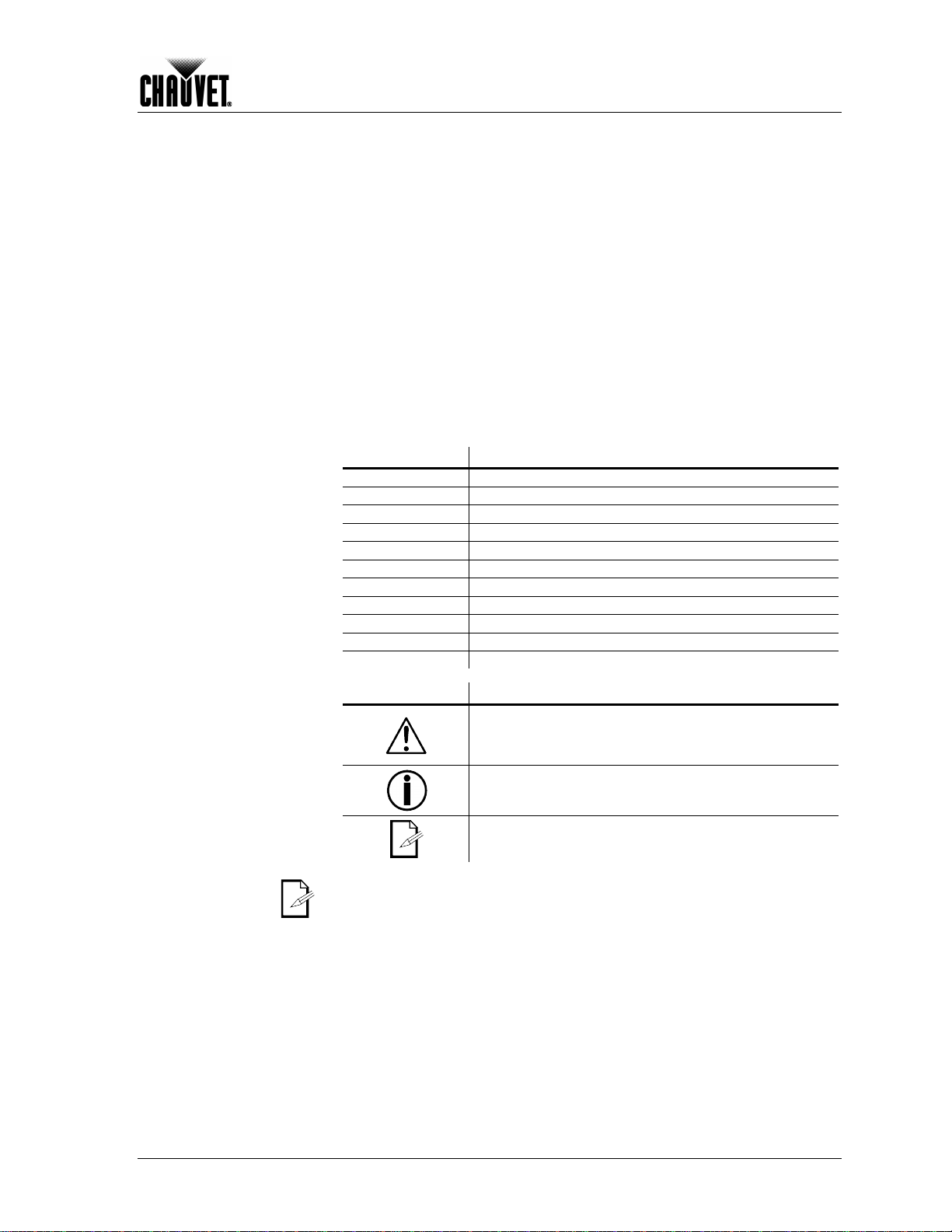
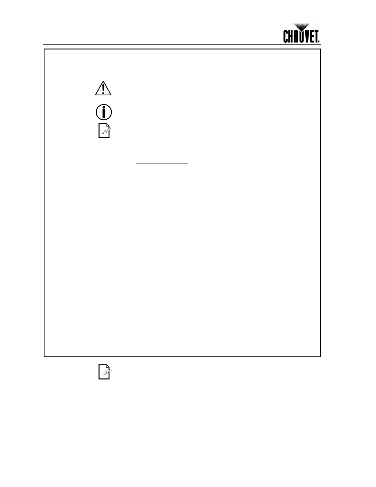
Icon Meaning
A new term, or a section or chapter in this document
This icon indicates crit ical installation, configuration, or op eration
information. Failure to comply with this information may render
the fixture partially or completely inoperative , damage third-party
This icon indicates important installation or configuration
information. Failure to comply with this information may pr ev en t
the fixture from functioning correctly.
Legend ™ 1200E Spot Us er M anu al Rev. 03c -1-
This icon indicates useful, although n on-c ritical inf orm at i on .
The term “ DMX” used throughout th is docum ent refers t o the USITT DMX512-A
transmission protocol.
Page 6
Before You Begi n
carefully because they include important safety
Safety Notes
Personal Safety
Mounting and Rigging
Please read the following notes
inform at i on ab ou t th e inst allation, usage, and maintenance of this product.
It is important to read all these notes before starting to work with this product.
There are no user serviceable parts inside this product. Any reference to
servicing it you may find from now on in this User Manual will only apply to
properly CHAUVET® certif ied technicians. Do not open the ho using or attempt
any repairs unless you are one of them.
Please refer to all applicable local codes and regulations for the proper
installation of this prod uct .
Keep this m anu al for future con sult ation. If yo u s el l this product to anot her user,
make sure that they also receive this manual.
• Avoid direct eye exp os ure to the ligh t s ource while th e fixture is on.
• Always disconnect this product from its power source before servicing.
• Lamp explosion hazard! Do not open the lamp cover within five minutes of having
turned off the fixture.
• The bulb remains hot for a long time after turn off. Never touch the bulb
barehanded and always handle it by its metallic contacts.
• Always connect this product to a grounded circuit to avoid the risk of electrocution.
• Do not touc h this product’s housing when operatin g b ec ause it may be ver y h ot.
• This product is for indoor use only! To prevent risk of fire or shock, do not expose
this produc t to rain or mois tu re.
• Make sure there are no flammable materials close to this product while operating.
• When hang in g t his pr oduct, alw ays s ec ur e it t o a fastening device using a safety
chain/cable (not provided).
• Do not carry this fixture from the head; use the handles instead.
Power and Wiring
• Always m ak e sure that you are connecting this product to the proper voltage, as
per the spec ifications in th is man u al or on th e product’s stic k er .
• Never connect this prod uc t to a dimmer pack or rheost at.
• Make sure the product’s housing or power cable are not cracked, crimped, or
damaged.
• Never disconnect this product by pulling or tugging on the power cable.
Operation
• Do not operate this fixture if you see damage on the housing, lenses, ultraviolet
filter, or c ab les; have th e dam aged parts r ep l ac ed by an authoriz ed technic i an at
once.
• Do not cover the ventilation slots when the fixture is operating to avoid internal
overheating.
• Do not aim this fixture toward the Sun. Otherwise, the lenses could concentrate the
solar energy and c aus e int er n al ov erheating .
• The maximum ambient temperature (Ta) is 104° F (40° C). Do not operate this
product at a higher temperatur e.
• In case of a serious operating problem, stop using this product immediately!
In the un likely event that your CHAUVET® product may requir e servic e, plea se
contact CHAUVET® Technical Support.
-2- Leg end ™ 120 0E S p ot User Manu al R ev. 03c
Page 7

2. Introduction
ich eliminates the need for a
voltage selection switch. The ballast and igniter in the lamp circuit are both of the
Introduction
Product
Description
Features
The Legen d™ 1 200E Sp ot is a movi ng yok e fi xt ure w ith a 1 200 W short ar c dis ch arge
lamp. It c ontai ns an LCD c ontrol panel ( disp lay), through whic h all of t he s ettings can
be set or modif ied.
This f ixture can operat e at 20 0~240 VAC , 50/60 Hz, wh
electronic type.
• 23 or 31-channel DMX moving yoke
• Pan 540⁰ in 2.8 sec
• Tilt 270⁰ in 1.6 sec
• Color wh eel:
Seven colors + white (red, blue, pink, green , m ag en ta, orang e, and UV)
Split/linear colors
Rainbow color spin at variable speeds
• Gobo wheel 1:
Indexed, rotating gobo wheel with gobo shake:
Six glass, slot-n-lock gobos + open (two multicolor, four B/W)
Gobo wheel spin at variable speeds
16-bit gobo r otation
• Gobo wheel 2:
Indexed, rotating gobo wheel with gobo shake:
Six glass, slot-n-lock gobos + open (one multicolor, five B/W)
Gobo wh eel sp i n at var iab l e spe eds
16-bit gobo r otation
• Variable frost
• Variable CTC filter (3,200~6,000 K)
• CMY color mi xi ng s ys t em w ith vec tor speed adj us tments
• 3-facet, 5-facet, 3D, and infinite prism with macros
• Variable shutter
• Variable iris
• Variable focus
• Variable 16-bit dimming (0~100%)
• Linear zoom (15~30⁰)
• Individual reset of pan/tilt, color, gobo, shutter, prism, focus
• Move-in-black for pan/tilt, color, gobo
• Remote fixture reset, lamp on/off, vector speed adjustments
• Built-in m ov em ent macros wit h r an g e adj ustments
• Built-in color macros
Additional Features
Options
Legend ™ 1200E Spot Us er M anu al Rev. 03c -3-
• 3-pin and 5-pin DMX connections
• Two additional free glass gobos
• User-configurable lamp ignition delay
• User-c onf igurable maintenance remi nd er
• Electronic ballast with power factor correction
• Electronic power supply
• Automatic pan & tilt correction
• Pan & tilt locks
• Lamp and fixture usage timer
• Power saver mode
• W-DMX (wireless DMX) receiver
• W-DMX (wireless DMX) transmitter
Page 8

Introduction
31-Channel Mode
23-Channel Mode
1
Pan 1
Pan
2
2
3
Tilt 3
Tilt 4 Tilt fine 4
Tilt fine
5
Pan/tilt speed
5 Pan/tilt speed
6
Dimmer 6
Dimmer
7
Dimmer fine
7 Shutter
8
Shutter 8
Color
9
Color 9
Cyan
10
10
11
Magenta
11
Yellow
12
12
13
3,200 K (CTO)
13
Gobo 1
14
14
15
Gobo 1 15
Gobo 2
16
Gobo 1 rotation
16
Gobo 2 rotation
17
Gobo 1 rotation fine
17
Focus
18
Gobo 2 18
Zoom
19
Gobo 2 rotation
19
Effect/prism
20
Gobo 2 rotation fine
20
Effect/prism rotation
21
Focus 21
Iris
22
22
23
Effect/prism
23
Function
24
25
Iris
26
27
Pan/tilt Movem en t macr o
28
Pan/ti lt M ov em en t m acro rang e
29
Preset Color
30
Color macro (CMY)
31
Function
DMX Channel Summary
Channel Function Channel Function
Pan fine
Cyan
Yellow
CMY/CTO Filter Speed
Pan fine
Magenta
3,200 K (CTO) Filter
Gobo 1 rotation
Zoom
Effect/prism rotation
Frost
-4- Leg end ™ 120 0E S p ot User Manu al R ev. 03c
Frost
Page 9
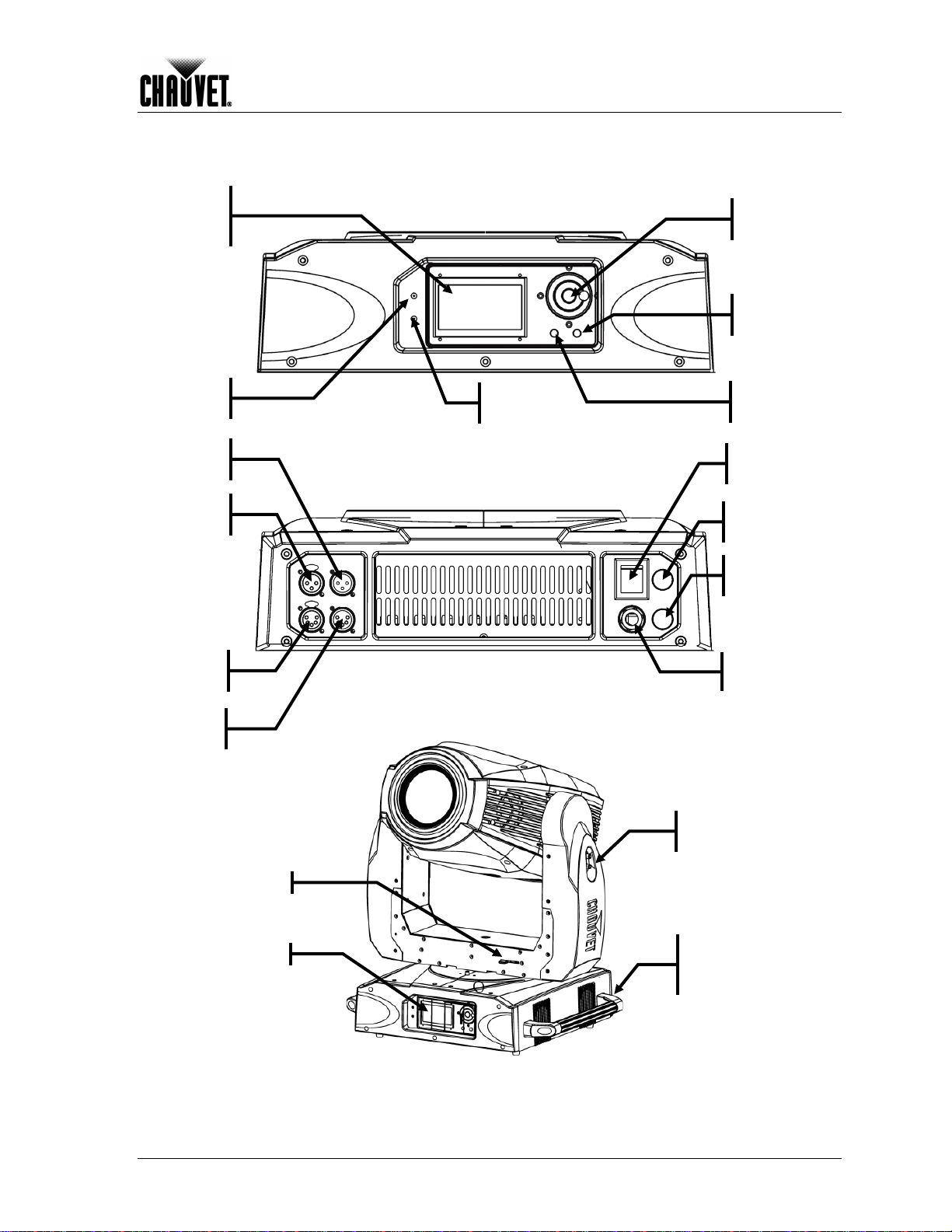
Product Overview
Power
input
ENTER
Liquid
Crystal
DMX out
Power LED
indicator
lock
Display
DMX in
(3-pin)
DMX out
(3-pin)
(5-pin)
DMX in
(5-pin)
Pan lock
Control panel
DMX LED
indicator
Introduction
Jog
Wheel
button
MENU
button
POWER
button
Fuse holder
(Main)
Fuse holder
(Lamp)
Tilt
Carrying
handle
(1 of 2)
Legend ™ 1200E Spot Us er M anu al Rev. 03c -5-
Page 10
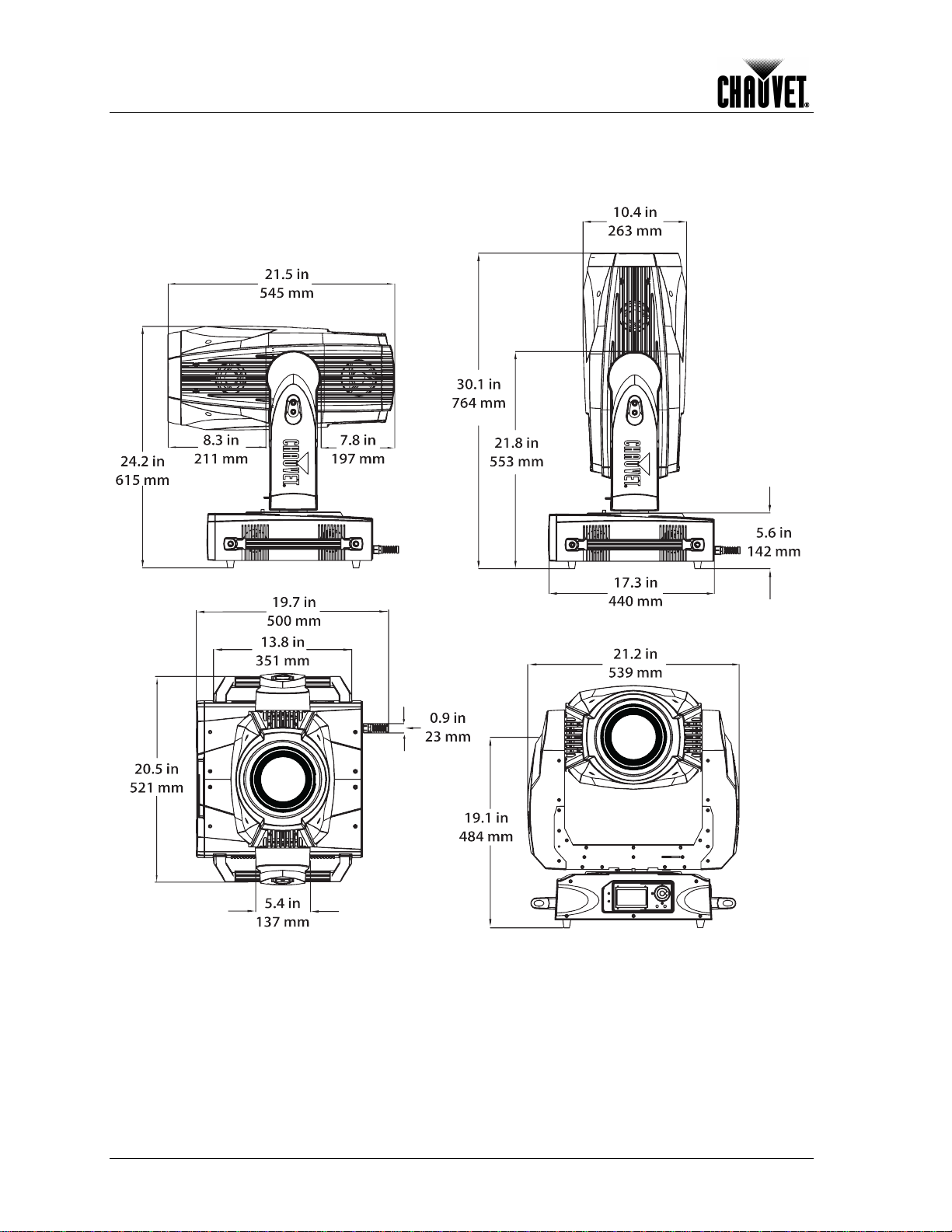
Introduction
Product Dimensions
-6- Leg end ™ 120 0E S p ot User Manu al R ev. 03c
Page 11
3. Setup
to a protected circuit with an
y download the “Sizing the Circuit Breakers” document
channel DMX modes. You will find
chapter (brief description), the
AC Power
AC Plug
The Legend™ 1200E Spot has an auto-ranging power s upply that c an work with an
input voltage range of 200~240 VAC, 50/60 Hz.
Make sure that you are connecting this product to the proper voltage, as per the
specifications in this guide, the product’s user manual, or on the product’s sticker.
Always connect the Legend™ 1200E Spot
appropriate elec tric al ground to avoid the risk of electr o cuti on o r fire.
To determine the power requirements for the Legend™ 1200E Spot see the label affixed
to the bottom of the fixture. Alternatively, you may refer to the corresponding
specifications chart in the Technical Informa t ion chapter of this manual.
The list ed curren t rating i ndicates t he maxim um curr ent draw dur ing norm al operat ion.
For more information, you ma
from the CHAUVET® Web site.
Never connect the Legend™ 1200E Spot to a rheostat (variable resistor) or
dimmer circuit, ev en i f th e r heostat or d immer c han n e l s er v es only as a 0 to 100%
switch.
The Leg end™ 12 00E Spot has a bare-ended power i nput c ord that is hard-wired to the
base of the fixture. Use the table below to wir e a plug for the power cord.
Connection
AC Live
AC Neutral
AC Ground
Make sure t o discon nect the fi xture’s po wer cord b efore repl acing a blo wn fuse,
and always replace it with a fuse of the same type and rating.
Wire (US) Wire (Euro pe)
Black Brown Yellow or Brass
White Blue
Green/Yellow Green/Yellow Green
Screw Color
Silver
Setup
Fuse Replacement
1) With a Phillips #2 screwdriver, unscrew the fuse holder from its housing.
2) Remo ve th e blown fuse from its h older and repl ace it with a good fuse of the exact
3) Screw the fuse holder back in its place and reconnect power.
DMX Linking
You may l ink any Leg end™ 1200E Sp ot fixture t o a DMX contr oller using a standard
DMX ser ial c onnecti on. If using other D MX com patib le fixtu res with a Leg end™ 1200E
Spot, it is possible to control them individually with a single DMX controller.
If you are n ot f amili ar with t h e DMX st and ard, or if you n eed inf or ma tion about the DM X
cables need ed to link th e Legend™ 12 00E Spot fi xture to a DMX c ontroller, you may
download the “DMX Primer” document from the CHAUVET® Web site.
DMX Modes
The Leg en d™ 1200E Spot can op erate in 23 and 31inform ation ab out these D MX modes in t he Introduction
Operation Instructions chapter (configuration details), and the DMX Values section
(individual channel values).
same type and rating.
Legend ™ 1200E Spot Us er M anu al Rev. 03c -7-
Page 12

Setup
Safety Cable Installation
Standing
Hanging
Safety
Omega
brackets
s
Mounting
Orientation
Rigging
Product Mounting
Diagram
Befor e m ounting this f ixture, read an d follow the saf ety recommen dations in dicated in
the Safety Notes section (pag e 2 of this manual).
Always m ount th is fixtur e in an y saf e position while m aking s ure that there is adequ ate
room around it for vent il ation, configurat i on, an d m aintenance.
Make sur e to mou nt this f ixture aw ay from any fl ammable m aterial as indicat ed in th e
Safety Notes section.
The Leg end™ 1 200E Spot comes with two omega br ackets and tw o clamps. You wil l
have to us e two m ounting points per fixtur e. You c an als o mount the Legend 1200E
Spot on the floor or any other firm, horizontal surface. CHAUVET® recommends
following the general guidelines below when mounting the Legend™ 1200E Spot.
• When sel ect in g an install at i on l oc ation, consi d er ease of access to the f i xture for
operation, progr am m in g adjustm ents , and routine maintenance.
• Never mount the fixture in places where rain, high humidity, extreme temperature
changes, or restricted ventilation may affect it.
• If hanging this fixture, make sure that the location where you are mounting the
fixture can support its weight. Please see the Technical Specifications section of this
manual for the weight requirement of this fixture.
Only mount this fi xture wher e the b ase is in a horiz ontal po sition, either h anging
or standing, as indicated in the diagram below. Doing otherwise may cause
damage to the fixture and void its warrant y .
position
Standing
position
position
-8- Leg end ™ 120 0E S p ot User Manu al R ev. 03c
Diagram
cable
with clamp
Page 13

Setup
Bracket Installation
Bracket Mounting
Diagram
Optics
You c an mount the includ ed brac kets on eit her si de of t he m ountin g plat e. This allow s
for pos itioning the fixtur e’s base in th e best poss ible orient ation to access the c ontrol
panel and the fuses.
Control Panel
Location 1
The Legen d 1200E Spot has one c olor wheel with sev en colors and two gob o wheels
that support six r otating, slot-n-lock gob os each. The colors in the col or wheel are not
replac eab le, but the g ob os ar e.
Location 2
Color Wheel
The di agram bel ow sh ows the color wh eel and th e names of each of the seven col or
filters on it.
Legend ™ 1200E Spot Us er M anu al Rev. 03c -9-
Page 14

Setup
Rotating Gobo Wheel 1
3
6 7 8
9 10
12
Gobo Wheels
The di agram bel ow s h ows both gobo wheels and th e numb er ass ign ed t o each gob o on
each wheel .
5
4
1
2
Rotating Gobo Wheel 2
11
-10- Leg end ™ 120 0E S p ot User Manu al R ev. 03c
Page 15

Setup
although it requires the technician to be careful
Removed
Replacing Gobos
The gob os in the Legend 12 00E Spot’s g obo wheels are removabl e from their g obo
plates. T his operati on is quite sim ple,
and to follow the recommended procedure.
• Make sure to disconnect the fixture’s power cord before replacing a gobo.
• Always replace a gobo with a gobo of the same dimensions.
• When inserting a glass gobo, a lways m ake sure t hat the shi nny sid e of the
gobo (glas s base) face s the lamp. T his provide s a layer of protection against
the high temperature from the lamp.
1) Turn the fixture off and disconnect it from the power outlet.
2) Open the head cover by loosening the four fastening screws at the sides of the top
cover.
3) Separate the gobo plate away from the gobo wheel by pushing it toward the front of
the moving head. Be careful not to push the gobo out of the gobo plate.
4) Once released from its slot, extract the gobo plate by pulling it outward.
5) On a flat surface, remove the expansion ring that holds the gobo in plac e and
remove the gobo fr om th e g ob o pl at e.
6) Insert a new gobo and hold it in pl ace with the exp ansion ring.
7) Slide the tip of the g ob o plat e under the pr ess ure plate near the center of the gobo
wheel.
8) Push the gobo plate inwards. DO NOT force the gobo plate into the gobo wheel slot.
If co rrectly installed, the gobo plate sho uld accommodate itself in the gobo wheel
slot.
Screws
Screws
Cover Screws Location
Gobo
Gobo Removal Sequence
Legend ™ 1200E Spot Us er M anu al Rev. 03c -11-
Page 16

Setup
Replacement
Lamp
Lamp
Procedure
Lamp Replacement
Diagram
The Legen d 1200E Sp ot is equip ped with a P hilli ps M SR1 200SA /S E F astFit lamp. T his
lamp us es a socket t hat all ows for f ast and eas y lamp chan ges. F ollow the pr ocedur e
below to safely c hange the Legend 1200E Spot’s lamp.
Never touch th e la mp ’s env e lop e (g la ss bul b) wit h y our b are ha nds . F ast Fit l am ps
do not require to uching t he lam p’s envel ope duri ng re moval or inst allati on. If you
touched the lamp’s envelope, clean it with isopropyl alcohol and wip e it with a
lint-free cl oth before installin g it.
1) Turn the fixture off and disconnect it from the power outlet.
2) Wait at least 15 minutes for the lamp to cool down.
3) Loosen the two screws on the lamp cover (marked “A” in the diagram).
4) Lift and rotate the lamp cover as per the diagram to expose the base of the lamp.
5) Rotate the ceramic base of the lamp 90º counterclockwise.
6) Pull the lamp out by holding it from its base only.
7) Insert the new lamp and turn it 90º clockwise.
8) Reverse steps 3 an d 4 .
9) Use the adjustment screws (marked “B” in the diagram) to position the lamp in the
center of the reflector to obtain the best output.
Lamp cover
FastFit Socket Positions
Increasing the
Lamp’s Life
• NEVER turn the fixture’s power off while the lamp is striking, as this can damage the
lamp perm an en t l y.
• ALWAYS turn the lamp off by using the DMX controller or the fixture’s control panel.
Locked Unlocked
Then wait at least five minutes before switching off the fixture. This will keep the
fans running to extract any remaining heat from the fixture’s head.
• ALWAYS wait 15 minutes to turn the lamp back on.
• DO NOT touch the lamp without wearing gloves to av oi d l eavi n g grease on the bulb
or on the contacts that could reduce the lamp’s life.
• ALWAYS change the lamp when it has reached its recommended lifespan to avoid
the risk of lamp explosion.
-12- Leg end ™ 120 0E S p ot User Manu al R ev. 03c
Page 17

4. Operation
DMX Mode
Error Indicator
ENTER button
Operation
Control Panel
Description
Control Panel Diagram
Home Screen
Button Function
<MENU> Exits from the current menu or function
<ENTER>
<JOG WHEEL>
Upon pow er up, t he LCD wi ll sh ow the L eg end log o and t he fi xtur e’s id entific at ion. Af t er
complet ing the pow er up tests, th e LCD will show th e DMX addr ess, the DMX mod e,
and the fixture’s temp eratur e, along with the warning s ign if the test s have d etect ed an
error.
DMX Address
• When the warning sign shows, press <ENTER> to read the corresponding
error message (see Error Messages in the Tech nic al Inf orm atio n chapter).
• Press <ENTER> while looking at an error messages to clear it.
Enables the currently displayed menu or sets the currently
selected value in to the current function
Navigates upwards through the menu list and increases the
numeric val u e wh en in a function
Jog wheel
MENU button
Fixture’s temperature
Control Options
Legend ™ 1200E Spot Us er M anu al Rev. 03c -13-
You can s et the L egen d™ 1200E Spot’s start addr ess in the 0 01~5 12 D MX r ang e. This
allows f or th e contr ol of u p to 22 f ixtur es in th e 23-c hann el DMX M ode 1 an d up to 16
fixtures in the 31-channel DMX Mode 2.
Page 18

Operation
DMX Address
1~512
Mode 1 (23)
Mode 2 (31)
View DMX Value
N/A
Active
Retransmit
Reset Memory
Pan Inver se
Tilt Inverse
Bl.o. P/T Moving
Bl.o. Color Change
Bl.o. Gobo Change
Auto Focus
On/Off
State/Power On
Off Via DMX
On if DMX On
Off if DMX Off
Cooling Mode
High/Auto
Ignition Delay
Low Power Delay
Display Inverse
Back Light Auto Off
Back Light Intensity
1~10
Temperature Unit
°C/°F
Auto Test
N/A
Manual Test
000~255
Fixture use time
N/A
Lamp On Time
Exit/ Reset Time
Firmwar e Version
N/A
Pan & Tilt
Color
Gobo & Iris
Shutter & Dimmer
Focus & Zoom
Prism & Frost
All
Fixture Maintenance
Interval/Remain Time
Factory Settin gs
Yes/No
Menu Map
Main Menu Level 2
DMX Functions
nd
Level 3rd Level 4th Level
WDMX Setting
(Requir es optional
W-DMX card)
N/A DMX Channel Mode
No/Yes
Fixture Setting s
Lamp Setting s
Display Settin gs
Fixture Test
Fixture Inform atio n
No/Yes N/A
On/Off
No/Yes
0~255
No/Yes
N/A
N/A
N/A
N/A
-14- Leg end ™ 120 0E S p ot User Manu al R ev. 03c
Reset Function
Special Functions
No/Yes N/A
N/A
Page 19

Operation
1 channels), do
Programming
Navigation Control
DMX Operation
DMX Address
DMX Modes
Carry out all th e pr ogr ammin g pr oced ur es ind ic ated bel ow f rom th e cont rol p anel . R ef er
to the Menu Map page to learn how the menu options relate to each other.
The Control Panel’s liquid crystal displa y (LCD) shows the menu items you select. When
you s el ec t a men u function, th e display will sh ow the availab le options f or the s elect ed
function with the f irs t one already highligh ted.
If not at the h om e sc r een, press <MENU> rep e atedly until th e h om e s c reen shows.
To enter programming mode from the home screen, press <MENU>. This is the first
menu level.
To highlight functions or options from a scr een, rotate the jog wheel and stop at th e
desired func t i on or op ti on .
To accept the highlight ed option, press <ENTER>. T his may open an other screen , as
per the Menu Map.
To activat e or en ab l e a sel ected option , pr ess <ENTER>.
To return to the previous screen without changing the current option’s value, press
<MENU>.
The Leg en d 1200E S p ot operat es al w ays i n s t an dard DM X m ode (no “ S lave,” “A uto,” or
“ID addr ess i ng” m od es). Th e opt i ons in the DM X O p er at i on section set the starting DMX
address and t h e DMX mod e as well as show t h e f i xt ur e’s DMX configur ati on . To access
this section, do the following:
1) Press <MENU>.
2) Select DMX Functions.
3) Select the corresponding function as indicated below.
4 Press <MENU> to exit once you are don e with this secti on.
To select the starting DMX address, do the following:
1) Select DMX Address.
2) Select a DMX address (001~512).
3) Press <ENTER>.
To s e lec t t h e D MX m od e, wh et he r B as ic (23 c hannels ) or Ad vanc ed (3
the following:
1) Select DMX Channel Mode.
2) Select Mode 1 (23) (Basic) or Mode 2 (31) (Advanced).
3) Press <ENTER>.
View DMX Values
This opt ion shows t he valu es for all t he fixtur e’s DMX fu nctions , from th e first ch annel
(starting address) to the last channel (23 for Basic and 31 for Advanced).
1) Select View DMX Value.
2) Press <ENTER> (the values will show on the s c reen).
3) Scroll with the jog wheel to see all values.
4) Press <MENU> to exit.
Fixture Settings
The opt ions in th e Fixture S ettings s ection s et the pan and tilt m odes as w ell as the
blackout options. To access this section, do the following:
1) Press <MENU>.
2) Select Fixtur e Setting s.
3) Select the corresponding function as indicated bel ow.
4) Press <MENU> to exit once you are done w it h t his s ecti on .
Pan Reversal
This opti on rev ers es th e pan angle ass ig nmen ts f rom 00 0 = 0º and 255 = 54 0º to 000 =
540º and 255 = 0º.
1) Select Pan Inverse.
2) Select Yes (reversed assignments) or No (nor mal assign m ents ) .
3) Press <ENTER>.
Continues on the ne xt pag e
Legend ™ 1200E Spot Us er M anu al Rev. 03c -15-
Page 20

Operation
Blackout During Head
Blackout During Color
Lamp On When DMX is
Continued from previous page
Tilt Reversal
This opt ion r everses t he tilt angle assign ments f rom 000 = 0 º and 2 55 = 270º to 000 =
270º and 255 = 0º.
1) Select Tilt Inverse.
2) Select Yes (reversed assignments ) or No (norm al assignments ) .
3) Press <ENTER>.
This option enables the black out feature while the f ixture head is moving ( panning or
Motion
tilting).
1) Select Bl. o. P/T Moving.
2) Select Yes (blac k ou t en abled) or No (b l ack ou t disabled).
3) Press <ENTER>.
This opti on en ables the bl ac k out f eature whil e the fixture is ch anging col ors.
Change
1) Select Bl.o. Color Change.
2) Select Yes (blac k ou t en abled) or No (b l ack ou t disabled).
3) Press <ENTER>.
Auto Focus
This opt ion enabl es the aut o focus f eature whi le the fi xture is z ooming f rom narr ow to
wide and vice versa.
1) Select Auto Focus.
2) Select Yes (auto focus enabled) or No (autofocus dis abl ed).
3) Press <ENTER>.
Lamp Settings
The Lam p Settings s ection c omprises all t he paramet ers that aff ect the fixt ure’s lamp
and its operation. To access this section, do the following:
1) Press <MENU>.
2) Select Lam p Setting s.
3) Select the corresponding function as indicated below.
4) Press <MENU> to exit once you are done w it h t his s ecti on .
-16- Leg end ™ 120 0E S p ot User Manu al R ev. 03c
Lamp On/Off
Immediate or Delayed
Lamp Strike
Lamp On/Off Remote
Control
Present
This opt ion allows turning t he lamp off and bac k on with out having to power c ycle th e
fixture.
1) Select On/Off.
2) Select Yes or No.
3) Press <ENTER>.
The lamp will turn on or off after pressing <ENTER>.
This option allow s the l amp to str ike immed iatel y (Yes) or in del ayed m ode (No) aft er
powering on the fixture. Delaying the lamp strike reduces the inrush current.
1) Select State/Power On.
2) Select Yes (immediate) or No (delayed).
3) Press <ENTER>.
The “Ignitio n D elay” o ption o n pag e 17 cont rols the delay bet ween power on an d
the lamp striking.
This opti on al lows the lam p t o tur n th e lam p off and back on from the DM X controller .
1) Select Off Via DMX.
2) Select Yes or No
3) Press <ENTER>.
When enabled (Yes), this op t i on turns the lam p on w h en DMX signal is present.
1) Select On if DMX On.
2) Select Yes or No
3) Press <ENTER>.
Continues on the ne xt pag e
Page 21

Operation
This option determines the speed of the cooling fans, whether always high or
Lamp Off When DMX is
Absent
Cooling Mode
Ignition Delay
Lamp Dousing
Display Settings
Display Reversal
Back Light Automatic Off
Continued from previous page
When enabled (Yes), this option turns the lamp off when DMX signal is absent.
1) Select Off if DMX Off.
2) Select Yes or No
3) Press <ENTER>.
automatic.
1) Select Cooling Mode.
2) Select High or Auto.
3) Press <ENTER>.
When the State/Power On option is act ive, t his setti ng c onfigur es the d elay b ef ore the
lamp stri k es after power on.
1) Select I gniti on Del ay .
2) Select the ignition delay in seconds (000 to 255).
3) Press <ENTER>.
This opti on decreases th e l am p p ow er aft er t he shutt er s /di m m er s h a ve been cl os ed for
a configurable time to reduce the internal heat accumulation.
1) Select Low Power Delay.
3) Select the time delay in seconds (000~255).
4) Press <ENTER>.
The opti ons in the D isplay S ettings s ection c ontrol th e operation of the fi xture’s LCD .
To access this section, do the following:
1) Press <MENU>.
2) Select Display Settings.
3) Select the corresponding function as indicated below.
4) Press <MENU> to exit once you are don e w it h t his s ecti on .
This opt ion revers es the LCD or ientation ( 180º) to r ead it uprig ht when the f ixture is
hanging from a truss.
1) Select On/Off.
2) Select Yes or No.
3) Press <ENTER>.
This opti on deter mines whether the LCD backlig ht will turn off autom atically after 30
seconds of control panel inactivity.
1) Select Back Light Automatic Off.
2) Select Yes or No.
3) Press <ENTER>.
Back Light Intensity
Th i s op ti on s elects the int ens ity of the LCD bac k li gh t.
1) Select Back Light Intensity.
2) Select 1~10.
3) Press <ENTER>.
Temperature Unit
When enabled (Yes), this op t i on turns the lam p on w h en D M X sig n al i s pres ent.
1) Select On if DMX On.
2) Select ºC ( Celsius) or ºF (Fahrenheit).
3) Press <ENTER>.
Continues on the ne xt pag e
Legend ™ 1200E Spot Us er M anu al Rev. 03c -17-
Page 22

Operation
Fixture Tests
Auto Test
Manual Test
Fixture Information
Fixture Operation Timer
Lamp Operation Timer
Firmware Version
Continued from previous page
The options in the Lamp Settings s ection c ontrol what tests the fixture will run. To
access this section, do the following:
1) Press <MENU>.
2) Select F ixtu re Tests .
3) Select the corresponding function as indicated below.
4) Press <MENU> to exit once you are done w it h t his s ecti on .
This option sets the fixture to run the automatic test.
1) Select Auto Test.
2) Press <ENTER>.
The fixture will run a single sequence of tests to verify all its functions.
This option allows the operator to select which tests to run.
1) Select Manual Test.
2) Select a function from the list (1~21).
3) Set th e val u e (000~255) for the selected function (the fixture will assume the new
functi on val u e, as if you had used a DMX controller) .
4) Press <ENTER>.
5) Repeat steps 2 through 4 for the other functions.
6) W hen d on e wit h th e tes t , press <MENU> ( the fixtur e will go back to DMX mode
and all the m anu al ly entered values will become 000).
The opti ons in the Fixture Inf orm at i on section control t h e fi xture usag e t i m ers and s how
the firmware version. To access this section, do the following:
1) Press <MENU>.
2) Select F ixtur e Information.
3) Select the corresponding function as indicated below.
4) Press <MENU> to exit once you are done w it h t his s ecti on .
This option shows the time the fixture has been in operation.
1) Select Fixture use time.
2) Press <ENTER>.
The fixture will show the accum ul at ed time of oper ati on .
The Fixture Use Time is not resettable.
This opt ion all ows th e oper ator see t he fi xture and lamp us age t imers as well t o reset
the lamp usage timer after changing the lamp.
1) Select Lamp On Time (the accumulated lamp usage time will show).
2) Select Exit or Reset Time (do this only after changing the lamp).
3) Press <ENTER>.
This option shows the installed firmware version for each of its various microcontrollers.
1) Select F ir mware Versi o n.
2) Press <ENTER>.
Fixture Reset
The options in the Fixture Res et section c ont r ol the r es ett ing of the various functi ons of
this fixture. To access this section, do the following:
1) Press <MENU>.
2) Select Reset Function.
3) Select the corresponding function as indicated below.
4) Press <MENU> to exit once you are done w it h t his s ecti on .
Continues on the ne xt pag e
-18- Leg end ™ 120 0E S p ot User Manu al R ev. 03c
Page 23

Operation
Continued from previous page
Pan & Tilt
This opti on resets the pan and tilt of the fixtur e’s head to their c orrespondin g home
positions.
1) Select Pan & Tilt.
2) Select Yes (reset) or No (exit without resetting).
2) Press <ENTER>.
The fixture’s will move to the pan and tilt home positions.
Color
This opti on r esets the color w h eel to its corresponding home position.
1) Select Color.
2) Select Yes (reset) or No (exit without resetting).
2) Press <ENTER>.
The c olor w h eel will move to its hom e position.
Shutter & Dimmer
This opti on r esets the shutter and dimmer to their corresponding home positions.
1) Select Shutter & Dimmer.
2) Select Yes (reset) or No (exit without resetting).
2) Press <ENTER>.
The shu tt er and dim m er will move to their corres p ond in g home positi ons .
Zoom
This opti on r esets the zoom to its home position.
1) Select Zoom.
2) Select Yes (reset) or No (exit without resetting).
2) Press <ENTER>.
The zoom wil l m ove to its home p osition.
All
This opti on r esets all th e mot ors to their corresponding home positions.
1) Select All.
2) Select Yes (reset) or No (exit without resetting).
2) Press <ENTER>.
All motors will move t o t h eir corresponding home positions.
Special Functions
Fixture Maintenance
Timers
The Special Functions section comprises the maintenance timer options and the
factory default option. To access this section, do the following:
1) Press <MENU>.
2) Select Special Functions.
3) Select the corresponding function as indicated below.
4) Press <MENU> to exit once you are done w it h t his s ecti on .
This f ixture has a built-in timer to remind the op erator that it is t ime f or th e fixtur e’s
routine maint enance. W hen the p reset time elapses, t he warni ng icon sh ows on th e
LCD.
1) Select Fixture Maintenance.
2) To change the main tenance interva l timer,
a) Select Interval.
b) Select the new in terval (in hours).
c) Press <MENU>.
3) To reset the remaining time counter,
a) Select Remain Time.
b) Select Reset Time (r es et t h e tim er ) or Exit (exit without resetting).
c) Press <MENU>.
Continues on the ne xt pag e
Legend ™ 1200E Spot Us er M anu al Rev. 03c -19-
Page 24

Operation
tilt movements. The home position is where
they do, use the
Factory Default
Offset Mode
Entering Offset
Mode
Pan Motor
Tilt Motor
Shutter Motor
Continued from previous page
If you want to default the fixture to its factory configuration, follow the following steps:
1) Select F act o ry Setting s.
3) Select Yes (default fixture) or No (exit without defaulting).
4) Press <ENTER>.
• The abov e operatio n will def ault all the f ixture’ s paramet ers to th eir original
factory configuration values.
• Defaulting the fixture does not affect the home position settings.
The Of f s et Mod e provides fine adj us t m en ts for the h om e position of all th e moving p art s
in the optic al path as w ell as the pan and
the moving parts go when you reset th em. In their correspond ing home posit ion, the
moving p arts sh ould not s how any b or der or r educ e t he li ght out put. If
Offset Mode to fine adjust them.
1) Press <MENU> to enter the regular Menu Mode.
2) Press <ENTER> for more than three seconds to enter the Offset Mode (the Offset
Mode menu will show).
4) Press <MENU> to exit once you are done w it h of f s et adjustmen ts .
1) Select Pan and pr ess <ENTER> ( a pop up w in d ow wil l op en).
a) Select the new value (-128~127).
b) Accept the new value.
1) Select Tilt and press <ENTER> (a pop up window will open).
a) Select the new value (-128~127).
b) Accept the new value.
1) Select Shutter and press <ENTER> ( a pop up wi nd ow w ill op en) .
a) Select the new value (0~255).
b) Accept the new value.
Color Motor
Cyan Dichroic Flag Motor
Magenta Dichroic Flag
Motor
Yellow Dichroic Flag
Motor
3200 K Filter Dichroic Flag
Motor
Gobo 1 Motor
1) Select Co lor 1 and press <ENTER> (a pop u p window will op en) .
a) Select the new value (-128~127).
b) Accept the new value.
1) Select Cyan and press <ENTER> (a pop up wind ow wi ll op en ) .
a) Select the new value (0~255).
b) Accept the new value.
1) Select Magenta and press <ENTER> ( a p op up w in dow will open).
a) Select the new value (0~255).
b) Accept the new value.
1) Select Yellow and press <ENTER> (a pop up wind ow will open).
a) Select the new value (0~255).
b) Accept the new value.
1) Select 3200 K Filter an d pr ess <ENTER> ( a p op up w in d ow wil l op e n) .
a) Select the new value (0~255).
b) Accept the new value.
1) Select Go bo 1 and press <ENTER>.
a) Select the new value (-128~127).
b) Accept the new value.
Continues on the ne xt pag e
-20- Leg end ™ 120 0E S p ot User Manu al R ev. 03c
Page 25

Operation
R-Gobo 1 Motor
Gobo 2 Motor
R-Gobo 2 Motor
Iris Motor
Prism Motor
R-Prism Motor
Frost Motor
Continued from previous page
1) Select R-Go bo 1 and press <ENTER>.
a) Select the new value (-128~127).
b) Accept the new value.
1) Select Go bo 2 and press <ENTER>.
a) Select the new value (-128~127).
b) Accept the new value.
1) Select R-Gobo 2 and press <ENTER>.
a) Select the new value (-128~127).
b) Accept the new value.
1) Select Iris and press <ENTER>.
a) Select the new value (0~255).
b) Accept the new value.
1) Select Prism and press <ENTER>.
a) Select the new value (0~255).
b) Accept the new value.
1) Select R-Prism and press <ENTER>.
a) Select the new value (-128~127).
b) Accept the new value.
1) Select Frost and pr ess <ENTER>.
a) Select the new value (0~255).
b) Accept the new value.
Focus Motor
Zoom Motor
1) Select Focus and press <ENTER>.
1) Select Zoom and press <ENTER>.
a) Select the new value (0~255).
b) Accept the new value.
a) Select the new value (0~255).
b) Accept the new value.
Legend ™ 1200E Spot Us er M anu al Rev. 03c -21-
Page 26

Operation
1
Pan
000 255
0~540º
2
Pan Fine
000 255
0~100%
3
Tilt
000 255
0~270º
4
Tilt Fine
000 255
0~100%
5
Pan/Tilt Speed
000 255
Fast~slow
6
Dimmer
240 255
Open
000 007
194 255
Open (white)
CW rotation (slow~fast)
9
Cyan
000 255
0~100%
10
Magenta
000 255
0~100%
11
Yellow
000 255
0~100%
12
3200 K Filter
000 255
0~100%
194 255
CW rotation (slow~fast)
194 255
CW rotation (slow~fast))
098 107
Gobo 10 shake
DMX Values
Mode 1 (Basic)
Channel Function Value Percent/Setting
7 Shutter
8 Color
13 Gobo 1
000 255 0~100%
000 007
008 015
016 131
132 167
168 203
204 239
008 015
016 023
024 031
032 039
040 047
048 055
056 063
064 127
128 189
190 193
000 009
010 019
020 028
029 038
039 047
048 057
058 067
068 077
078 087
088 097
098 107
108 117
118 127
128 189
190 193
Closed
Open
Macro 1 (open~closed) (slow~fast)
Macro 2 (open~closed) (fast~slow)
Macro 3 (open~closed) (slow~fast~slow)
Random Strobe
Red
Dark Blue
Pink
Green
Yellow
Orange
UV
Split Colors
CCW rotation (fast~slow)
Stop
Open (white)
Gobo 1
Gobo 2
Gobo 3
Gobo 4
Gobo 5
Gobo 6
Gobo 1 shake
Gobo 2 shake
Gobo 3 shake
Gobo 4 shake
Gobo 5 shake
Gobo 6 shake
CCW rotation (fast~slow)
Stop
-22- Leg end ™ 120 0E S p ot User Manu al R ev. 03c
14 R-Gobo 1
15 Gobo 2
000 127
128 189
190 193
000 009
010 019
020 028
029 038
039 047
048 057
058 067
068 077
078 087
088 097
Continues on the ne xt pag e
Gobo indexing
CCW rotation (fast~slow)
Stop
Open (white)
Gobo 7
Gobo 8
Gobo 9
Gobo 10
Gobo 11
Gobo 12
Gobo 7 shake
Gobo 8 shake
Gobo 9 shake
Page 27

Operation
Mode 1 (Cont.)
108 117
194 255
Gobo 11 shake
CW rotation (slow~ fast)
000 127
Gobo indexing
17
Focus
18
Zoom
000 255
15~30°
000 025
128 255
Open
Effect Macro 1~24
000 127
Gobo indexing
21
Iris
000 179
0~100%
000 009
240 255
No function
No function
Continued from previous page
Channel Function Value Percent/Setting
Gobo 2
15
(Cont.)
16 R-Gobo 2
19 Effect/prism
20 R-Effect/Prism
22 Frost
118 127
128 189
190 193
128 189
190 193
194 255
000 255 Narrow~wide
026 050
051 076
077 101
102 127
128 189
190 193
194 255
000 255 100~0%
180 201
202 223
224 245
246 255
Gobo 12 shake
CCW rotation (fast~slow)
Stop
CCW rotation (fast~slow)
Stop
CW rotation (slow~fast)
Effect 1
Effect 2
Effect 3
Effect 4
CCW rotation (fast~slow)
Stop
CW rotation (slow~fast)
Open closed (fast~slow)
Closed open (fast~slow)
Frost
Fr ost effect
23 Function
010 019
020 029
030 039
040 049
050 069
070 079
080 089
090 099
100 109
110 119
120 129
130 139
140 149
150 159
160 169
170 179
180 189
190 199
200 209
210 219
220 229
230 239
End of Mode 1
Auto focus (enable)
Auto focus (disable)
Fan speed (auto)
Fan speed (high )
No function
Pan/tilt move-in-black (enable)
Pan/tilt move-in-black (disable)
Color m ove-in-black (enable)
Color m ove-in-black (disable)
Gobo move-in-blac k ( en able)
Gobo move-in-black (disable)
Lamp On
Pan/tilt reset
Color reset
Gobo1/Gobo2/Iris reset
Shutter reset
Focus/zoom reset
Frost/effect reset
Reset a ll
Pan/tilt/color/gobo move-in-black (enable)
Pan/tilt/c ol or/g obo m ov e-in-black (disable)
Lamp off
Legend ™ 1200E Spot Us er M anu al Rev. 03c -23-
Page 28

Operation
1
Pan
000 255
0~540
2
Pan fine
000 255
0~100%
3
Tilt
000 255
0~270
4
Tilt fine
000 255
0~100%
5
Pan/tilt Speed
000 255
Fast~slow
6
Dimmer
000 255
0~100%
7
Dimmer fine
000 255
0~100%
000 007
194 255
Open (white)
CW rotation (slow~fast)
10
Cyan
000 255
0~100%
11
Magenta
000 255
0~100%
12
Yellow
000 255
0~100%
13
3200 K Filter
000 255
0~100%
14
Filters Speed
000 255
Fast~slow
194 255
CW rotation (slow~fast)
194 255
CW rotation (slow~fast))
17
R-Gobo 1 Fine
000 255
0~100%
088 097
Gobo 9 shake
Mode 2
(Advanced)
Channel Function Value Percent/Setting
8 Shutter
9 Color
15 Gobo 1
000 007
008 015
016 131
132 167
168 203
204 239
240 255
008 015
016 023
024 031
032 039
040 047
048 055
056 063
064 127
128 189
190 193
000 009
010 019
020 028
029 038
039 047
048 057
058 067
068 077
078 087
088 097
098 107
108 117
118 127
128 189
190 193
Closed
Open
Macro 1 (open~closed) (slow~fast)
Macro 2 (open~closed) (fast~slow)
Macro 3 (open~closed) (slow~fast~slow)
Random Strobe
Open
Red
Dark Blue
Pink
Green
Yellow
Orange
UV
Split Colors
CCW rotation (fast~slow)
Stop
Open (white)
Gobo 1
Gobo 2
Gobo 3
Gobo 4
Gobo 5
Gobo 6
Gobo 1 shake
Gobo 2 shake
Gobo 3 shake
Gobo 4 shake
Gobo 5 shake
Gobo 6 shake
CCW rotation (fast~slow)
Stop
-24- Leg end ™ 120 0E S p ot User Manu al R ev. 03c
16 R-Gobo 1
18 Gobo 2
000 127
128 189
190 193
000 009
010 019
020 028
029 038
039 047
048 057
058 067
068 077
078 087
Continues on the ne xt page
Gobo indexing
CCW rotation (fast~slow)
Stop
Open (white)
Gobo 7
Gobo 8
Gobo 9
Gobo 10
Gobo 11
Gobo 12
Gobo 7 shake
Gobo 8 shake
Page 29

Operation
Mode 2 (Cont.)
098 107
194 255
Gobo 10 shake
CW rotation (slow~fast)
194 255
CW rotation (slow~fast))
20
R-Gobo 2 Fine
000 255
100~0%
21
Focus
000 255
Narrow~wide
22
Zoom
000 255
15~30°
128 255
Effect Macro 1~24
000 127
194 255
Gobo indexing
CW rotation (slow~fast))
25
Iris
000 255
100~0%
000 179
246 255
0~100%
Fr ost effect
000 007
248 255
Off
Macro 27
28
Macro Range
000 255
0~100% (works with Channel 27)
Continued from previous page
Channel Function Value Percent/Setting
Gobo 2
18
(Cont.)
19 R-Gobo 2
23 Effect/prism
24 R-Effect/prism
26 Frost
108 117
118 127
128 189
190 193
000 127
128 189
190 193
000 025
026 050
051 076
077 101
102 127
128 189
190 193
180 201
202 223
224 245
Gobo 11 shake
Gobo 12 shake
CCW rotation (fast~slow)
Stop
Gobo indexing
CCW rotation (fast~slow)
Stop
Open
Effect 1
Effect 2
Effect 3
Effect 4
CCW rotation (fast~slow)
Stop
Open~closed (fast~slow)
Closed~open (fast~slow)
Frost
Pan/tilt Macro
27
(works with Channel
28)
008 015
016 023
024 031
032 039
040 047
048 055
056 063
064 071
072 079
080 087
088 095
096 103
104 120
121 127
128 135
136 143
144 151
152 159
160 167
168 175
176 183
184 191
192 207
208 223
224 231
232 247
Macro 1
Macro 2
Macro 3
Macro 4
Macro 5
Macro 6
Macro 7
Macro 8
Macro 9
Macro 10
Macro 11
Macro 12
Macro 13
Macro 14
Macro 15
Macro 16
Macro 17
Macro 18
Macro 19
Macro 20
Macro 21
Macro 22
Macro 23
Macro 24
Macro 25
Macro 26
Continues on the ne xt pag e
Legend ™ 1200E Spot Us er M anu al Rev. 03c -25-
Page 30

Operation
Mode 2 (Cont.)
000 021
234 255
White
Color 11
000 009
No function
Continued from previous page
Channel Function Value Percent/Setting
29 Preset Color
30 Color Macro
31 Function
022 042
043 063
064 085
086 106
107 127
128 148
149 170
171 191
192 212
213 233
000 007
008 028
029 049
050 069
070 090
091 110
111 131
132 152
153 173
174 194
195 215
216 235
236 255
010 019
020 029
030 039
040 049
050 069
070 079
080 089
090 099
100 109
110 119
120 129
130 139
140 149
150 159
160 169
170 179
180 189
190 199
200 209
210 219
220 229
230 239
240 255
End of Mode 2
Color 1
Color 2
Color 3
Color 4
Color 5
Color 6
Color 7
Color 8
Color 9
Color 10
Open
Macro 1
Macro 2
Macro 3
Macro 4
Macro 5
Macro 6
Macro 7
Macro 8
Macro 9
Macro 10
Macro 11
Macro 12
Auto focus (enable)
Auto focus (disable)
Fan speed (auto)
Fan speed (high )
No function
Pan/tilt move-in-black (enable)
Pan/tilt move-in-black (disable)
Color m ove-in-black (enable)
Color m ove-in-black (disable)
Gobo move-in-blac k ( en able)
Gobo move-in-black (disable)
Lamp On
Pan/tilt reset
Color reset
Gobo1/Gobo2/Iris reset
Shutter reset
Focus/zoom reset
Frost/effect reset
Reset a ll
Pan/tilt/c ol or/g obo m ov e-in-black (enable)
Pan/tilt/c ol or/g obo m ov e-in-black (disable)
Lamp off
No function
-26- Leg end ™ 120 0E S p ot User Manu al R ev. 03c
Page 31

5. Technical Information
General
Maintenance
To maintai n optimum per formanc e and minimi ze wear, the us er should cl ean the light
fixtures fr equentl y. Us age and envir onm ent are c ontr ibutin g f actors in det erminin g th e
cleani ng f requenc y. A s a rule, the user sh oul d c lean the fixtures at l e ast twice a m onth.
Dust buil d up red uces ligh t output perform ance and c an cause overheati ng. This can
lead to reduced light s ource life and inc reased m ec h anical wear .
CHAUVET® rec ommends cleaning t he fixtur e’s exter nal optic s with a s oft cloth usi ng
normal glass cleaning fluid.
To clean a fixture, follow the recommendations below:
• Unplug the fixture from power.
• Wait until the fixture is cold.
• Use a vacuu m (or dr y c ompress ed air) an d a s oft brus h to remove du s t coll ec t ed
on the external vents and r eac h abl e internal c omp on en ts .
• Clean all external optics and gl ass surfaces with a mild solut i on of gl a s s clean er or
isoprop yl alcohol, and a soft, lint free cotton cloth or a lens cleaning tissue.
• Apply the solution directly to the cloth or tissue and drag any dirt and grime to the
outsid e of the lens.
• Gentl y polish the exter n al gl ass s ur f ac es unt i l th ey are free of haz e a nd li nt .
• When cleaning units w it h a mo vab l e mir r or , y ou s h ould keep the c ontact with th e
mirror surface to a minimum to avoid scratching or damaging it.
Technical Information
Dust Screen
Cleaning
Always dry the external optics and glass surfaces carefully after cleaning them.
If the fixture ha s on e or m or e f an s, refr ain fr o m s pin nin g the m using co mpressed
air.
The Legend 1200E Spot fixture uses multiple fans. To prevent dust buildup on the
componen ts of t he optic path, eac h of th e fans on the for ward s ection of t he movin g
head have a dust screen as shown in the diagram below.
To acc ess th e dus t sc reens, r em ove the b ott om an d top h ous ings of t he m ovin g head ,
at which point you will have be able to remove the housing sides. Once you have
cleaned the dust screens, reverse the process to replace them.
Despite havi ng dus t scre ens, t he f ixt ure stil l nee ds r egu lar cl e aning of i ts len ses,
color wheels, and the other components in the optical path.
Legend ™ 1200E Spot Us er M anu al Rev. 03c -27-
Page 32

Technical Information
Check ballast and igniter
Check control board
Clean v ents
Clean v ents
Maintenance Fixture
Proc eed w it h m aintenanc e an d r es et ti m er
Lamp On Over 700 Hour
Lamp ch ang e is over due.
Change lamp
Memory Initial Fail
Change main board
Fan 1 Error
Fan 6 Error
The indicated fan is not working.
CPU H Error
There is no communication with the
The moving head failed going to home
Error Messages
Message Cause(s) Action(s)
Lamp Startup Fail The lamp has not started after being
Temperature Sense Fail There is no communication with
Lamp Hot Protection Fixture temperature is hi gh er th an 105º C;
Lamp Hot Power Off Fixture temperature is 110º C or higher;
Fan 2 Error
Fan 3 Error
Fan 4 Error
Fan 5 Error
CPU-B Error
CPU-C Error
CPU-D Error
CPU-E Error
CPU F Error
CPU G Error
struck.
temperature sensor.
lamp was switched to low power for safety.
lamp was switched to off for safety.
Fixture M aintenance timer exp ired.
Memory chip error found.
indicated auxiliary CPU.
• Check lamp
• Check lamp socket and wiring
•
• Check sensor wiring
• Check sensor integrity
•
• Check fans
• Check fan wiring
•
• Check fans
• Check fan wiring
•
•
•
•
• Check fan
• Check fan wiring
• Check sensors’ wiring and p osi t i on
• Check stepper motor, belt, and driver board
• Check control boards
Pan Home Sensor Error
Pan Encode Error
Tilt Home Sensor Error
Tilt Encode Error
Color 1 Reset Fail
Cyan Reset Fail
Magenta R e set Fa il
Yellow Reset Fail
3200 K Filter Reset Fail
Gobo 1 Reset Fail
R-Gobo 1 Res et Fail
Gobo 2 Reset Fail
R-Gobo Reset Fail
Iris Reset Fail
Effect Reset Fail
R-Effect Reset Fail
Frost Reset Fail
Focus Reset Fail
Zoom Reset Fail
positi on after power up or fi xtu re reset.
The ind icated movi n g p art f ailed g oi ng t o
home position after power up or fixture
reset.
• Check moving head’s free movement
• Ch eck s ens ors ’ w iring and posi ti on
• Check stepper motor, belt ,and driver board
• Check the corresponding control board
• Check main control board
• Check part’s free movement and integrity
• Ch eck s ens ors ’ w iring and posi ti on
• Check stepper motor, belt, and driver board
• Check the corresponding control board
• Check main control board
-28- Leg end ™ 120 0E S p ot User Manu al R ev. 03c
Page 33

Troubl es h oo ti n g Guide
Symptom
Cause(s)
Action(s)
• No power on ou t l et • Repair ou tl et problem or us e an oth er out let
• Blown fuse • Replace blown fuse with same type and rating
Fixture does not pow er up
Fixture powers up but
lamp does not ignit e
Lamp ignited but has low
intensity/color
temperature
Lamp fli ckers or t u rns of f
by itself
Circuit breaker/fuse keeps
tripping/blowing
Fixture does not respond
to DMX when n earby
fixtures on the same
universe do
DMX signal problems
• Bad power cord/plug • Repair or replace power cord/plug
• Bad power switch • Replace power switch
• Bad power supply • Replace power supply
• Bad main controller • Replace main controller
• State/Power On parameter set to NO • Change p ar am et er to Y ES
• Lamp temperature problems • Ch eck err or m essages and follow instructions
• Lamp problems • Check err or m essages and follow ins truc tions
• Dimmer not at full output • Adjus t dimmer v alue
• Lamp still cold • Wait for lamp to come up with full output
• CTC or CMY filter interfering • Set color wheel or filter to home position
• Defect i ve or ol d lam p • Replace lamp
• Misaligned lamp • Realign lamp
• Defec ti v e lam p wires or socket • Repair/c h ange wiring or s oc k et
• Defec ti v e bal las t • Replace balla s t
• Defect i ve or ol d lam p • Replace lamp
• Temper at ur e problems • Check err or m essages and follow ins truc tions
• Defec ti v e lam p wires or socket • Repair/c h ange wiring or s oc k et
• Defec ti v e bal las t • Replace balla s t
• Excessive circuit load • Check total load placed on the electrical circuit
• Short circuit along the power wires • Check fo r a short in the electrical wi ring
• Wrong D M X addressin g • Check DMX mod e and st art in g D M X address
• Damaged DMX cables • Check DMX cables
• Wrong polarity on th e c ontroller • Check polarity switch settings on the controller
• Loose DMX cables • Check cable connectio ns
• Faulty DMX interface • Replace t he Main board
• Faulty Display/Main board • Replace the Main board
• Non DMX cables • Use only DMX compatible cables
• Bouncing signals • Ins tall termi n at or as su gg es t ed
• Long cable / low level signal • Install an optically coupled DMX splitter right
• Too many fixtures • Install an optically coupled DMX splitter after
• Interference from AC wires • Keep DMX cables separated from power
Technical Information
fuse
temperature
after the fixture with the strong signal
unit #32 or before
ca b les or fluorescent/black lights
If you still experience technical problems after trying the above solutions, contact
CHAUVET® Technical Support.
Legend ™ 1200E Spot Us er M anu al Rev. 03c -29-
Page 34

Technical Information
with its original
to have
manner may
Returns
Procedure
Claims
Contact Us
The us er must s end the mer chandis e prepaid, in the origin al box, and
packi ng a nd ac cess ori es. CHA UVE T® will not issue call tags.
Call CHAUVET® and request a Return Merchandise Authorization Number (RMA #)
before s hipping th e fixture. B e prepared t o provide t he model nu mber, seri al number,
and a brief description of the cause for the return.
The user must clearly label the package with a Return Merchandise Authorization
Number (RMA #). CHAUVET® will refuse any product returned without an RMA #.
DO NOT write t he R MA # directly on the box. In ste ad, wr ite it on a pro per ly a ffix ed
label.
Once you receive the RMA #, please include the following information on a piece of
paper inside the box:
• Your name
• Your addr es s
• Your phone number
• The RMA #
• A brief description of the problem
Be sure to p ack th e fixture prop erly. Any shipping damag e resul ting from inad equate
packaging will be the c us t omer’s r es p ons ib il ity. As a sugges ti on, pro p er U PS p ac ki ng or
double-boxing is always a safe method to use.
CHAUVET® reserves the right to use its own discretion to repair or replace
returned product(s).
The carrier is r esp onsibl e for any damag e incurred du r i ng s hi pping t o t his pr oduct or any
part that shipped with it. Therefore, if the received merchandise appears
damages caus ed durin g s hi pp ing, the cus tomer mus t s ubmit the d am age report an d any
related c laims with th e carri er, not C HAUVET ®. The cus tomer must s ubmit th e report
upon rec eption of th e dam aged m erchan dise. Failur e to d o so in a timel y
invalidate the customer’s claim with the carrier.
For other iss ues s uch as mis sing c om pon ents or p arts , dam age n ot r elat ed to s hipp in g,
or conc eal ed d amag e, t he c ust omer must make clai ms t o CH AUVE T ® within s even (7)
days of rec ei vi ng t h e m erc handise.
World Headquarters
General Inform ation
CHAUVET®
5200 NW 108th Avenue
Sunrise, FL 33351
Voice: (954) 929-1115
Fax: (954) 929-5560
Toll free: (800) 762-1084
Technical Supp or t
Voice: (954) 929-1115 (Press 4)
Fax: (954) 756-8015
World Wide Web
www.chauvetlighting.com
-30- Leg end ™ 120 0E S p ot User Manu al R ev. 03c
Page 35

Technical Specifications
Dimensions and Weight
Fixture Only
Length
Width
Height
Weight
Fixture in Flight Case
Length
Width
Height
Weight
25 in (635 mm)
28 in (711 mm)
35 in (889 mm)
191.05 lbs (86.22 kg)
Power
Power Supply Type
Range
Voltage Selection
Switching (w/PF correction)
100~240 V, 50/60 Hz
Auto-ranging
Parameter
208 V, 60 Hz
230 V, 50 Hz
Consumption
1,641 W (7.89 A)
1,645 W (7.15 A)
Inrush current
3.4 A
3.3 A
Fuse
F 15 A, 250 V, 6 x 30 mm (fast blow)
Power I / O
Input
Output
Connectors
Cable boot
N/A
Cord plu gs
Bare ended
N/A
Light Source
Type
Power
Quantity
HID Lamp (short arc)
1200 W
1
Socket
Lifespan
Appr oved Lamps
Phillips
Osram
GE
Head Movement
Pan Range
Tilt Range
Fine Adjustm ent Option
Gobos
Externa l Diameter
Image Diameter
Thickness
37.3 mm
30.0mm
5 mm.
Photo Opt ic
Parameter
Minimum Zoom
Maximum Zoom
Illuminance @ 5 m
23,000 lx
5,000 lx
Beam angl e
15º
30º
Thermal
Maximum External Temp.
Maximum Surface Temp.
Cooling Syste m
DMX
I/O Connectors
Connector Type
Channel Range
3- and 5-pi n X LR
Sockets
23 and 31
Ordering
Legend™ 1200E Spot
Flight Case
LEGEND1200ESPOT
Included
Warranty
Duration
Coverage
Details
2 years
Limited
See Warranty Card
20.5 in (521 m m) 21.2 in (539 mm) 30.1 in (764 mm) 82.05 lbs (37.22 kg)
Technical Information
MSR1200SA/SE FastFit™ HTI 1500 W/60/P50 Lok-It™ CSR 1200/SA/TAL
PGJX50 750 (50% failure)
0~540º 0~270º Yes (Advanced Mode)
104° F (40° C) 135° F (57° C) Fans
Legend ™ 1200E Spot Us er M anu al Rev. 03c -31-
Page 36

CHAUVET®
5200 NW 108th Avenue
Sunrise, FL 33351 (USA)
(800) 762-1084 – ( 95 4) 92 9-1115
FAX (954) 929-5560
www.chauvetlighting.com
Legend™ 1200E Spot User Manual Rev. 03c
October 2010
 Loading...