

Page 1
J-Five™
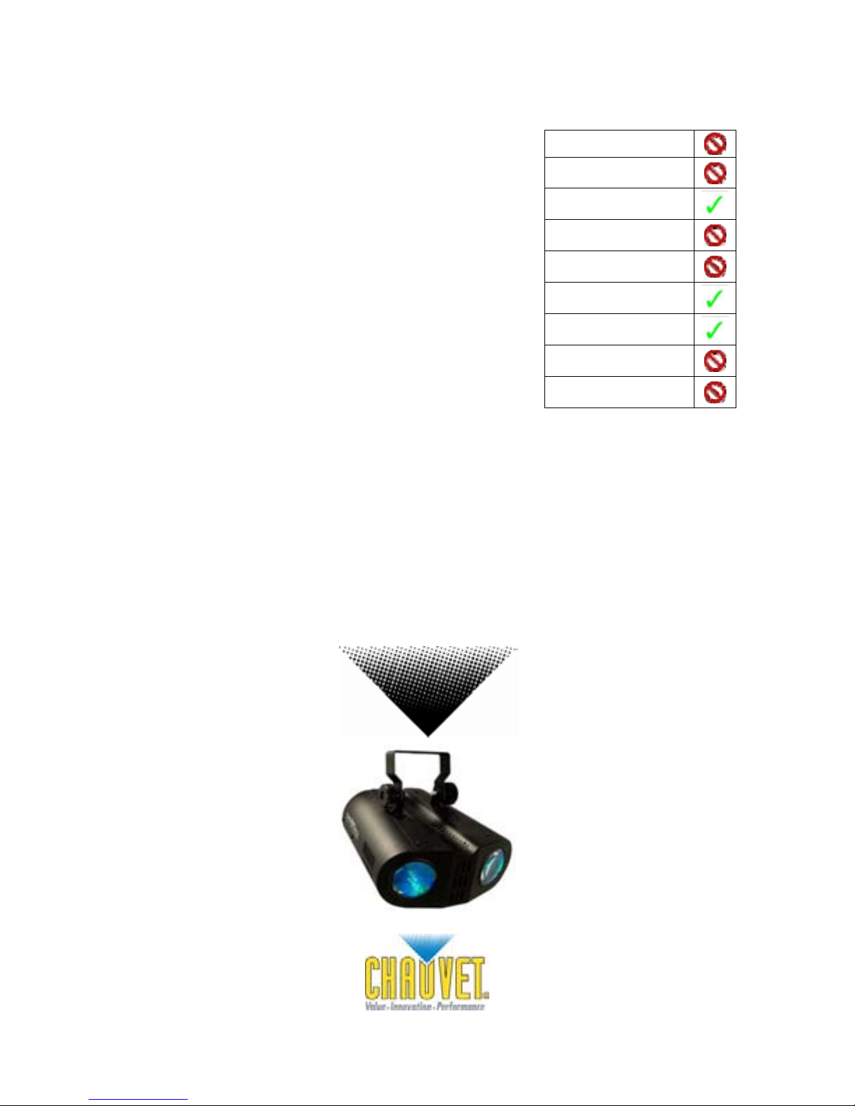
Snapshot
OK on Dimmer
Outdoor OK
Sound Activated
DMX512
Master/Slave
115V/230V Switch
Replaceable Fuse
User Serviceable
Duty Cycle
USER MANUAL
Chauvet, 3000 N 29th Ct, Hollywood, FL 33020 U.S.A.
(800) 762-1084 – (954) 929-1115
FAX (954) 929-5560
www.chauvetlighting.com
Page 2

TABLE OF CONTENTS
1. BEFORE YOU BEGIN................................................................................................................................3
W
HAT IS INCLUDED................................................................................................................................................................................3
U
NPACKING INSTRUCTIONS....................................................................................................................................................................3
POWER...........................................................................................................................................................................................3
AC
ONTACT US........................................................................................................................................................................................3
C
AFETY INSTRUCTIONS..........................................................................................................................................................................4
S
2. INTRODUCTION ........................................................................................................................................ 5
F
EATURES............................................................................................................................................................................................5
RODUCT OVERVIEW ............................................................................................................................................................................5
P
3. SETUP.............................................................................................................................................................................................. 6
F
USE REPLACEMENT.............................................................................................................................................................................6
OUNTING ...........................................................................................................................................................................................6
M
Orientation.............................................................................................................................................................................6
Rigging ..................................................................................................................................................................................6
4. OPERATING INSTRUCTIONS................................................................................................................... 7
T
ROUBLESHOOTING...............................................................................................................................................................................7
ENERAL TROUBLESHOOTING................................................................................................................................................................8
G
ECHNICAL SUPPORT............................................................................................................................................................................8
T
G
ENERAL MAINTENANCE .......................................................................................................................................................................9
ETURNS PROCEDURE..........................................................................................................................................................................9
R
LAIMS ................................................................................................................................................................................................9
C
ECHNICAL SPECIFICATIONS ................................................................................................................................................................10
T
J-Five 2 9/18/2007 2:53 PM
Page 3

1. BEFORE YOU BEGIN
What is included
¾ 1 x J-Five™
¾ Power Cord
¾ Warranty Card
¾ User Manual
Unpacking Instructions
Immediately upon receiving a fixture, carefully unpack the carton, check the contents to ensure that
all parts are present, and have been received in good condition. Notify the shipper immediately and
retain packing material for inspection if any parts appear damaged from shipping or the carton itself
shows signs of mishandling. Save the carton and all packing materials. In the event that a fixture
must be returned to the factory, it is important that the fixture be returned in the original factory box
and packing.
AC Power
To determine the power requirements for a particular fixture, see the label affixed to the back plate of
the fixture or refer to the fixture’s specifications chart. A fixture’s listed current rating is its average
current draw under normal conditions. All fixtures must be powered directly off a switched circuit and
cannot be run off a rheostat (variable resistor) or dimmer circuit, even if the rheostat or dimmer
channel is used solely for a 0% to 100% switch. Before applying power to a
fixture, check that the source voltage matches the fixture’s requirement.
Check the fixture or device carefully to make sure that if a voltage selection
switch exists that it is set to the correct line voltage you will use.
Warning! Verify that the voltage select switch on your unit matches the
line voltage applied. Damage to your fixture may result if the
line voltage applied does not match the voltage indicated on
the voltage selector switch. All fixtures must be connected to
circuits with a suitable Earth Ground.
Figure 1 - AC Voltage Switch
Not all fixtures have a voltage
select switch. Please be sure to
connect to the proper voltage.
Contact Us
World Wide
General Information Chauvet Lighting
Technical Support Chauvet Lighting
World Wide Web www.chauvetlighting.com
J-Five 3
3000 North 29
Hollywood, FL 33020
voice: 954.929.1115
fax: 954.929.5560
toll free: 800.762.1084
3000 North 29
Hollywood, FL 33020
voice: 954.929.1115 (Press 4)
fax: 954.929.5560 (Attention: Service)
th
Court
th
Court
9/18/2007 2:53 PM
Page 4

Safety Instructions
Please read these instructions carefully, which includes important
information about the: installation, usage and maintenance of this
product.
• Please keep this User Guide for future consultation. If you sell the unit to another user, be sure that
they also receive this instruction booklet.
• Always make sure that you are connecting to the proper voltage, and that the line voltage you are
connecting to is not higher than that stated on the decal or rear panel of the fixture.
• This product is intended for indoor use only!
• To prevent risk of fire or shock, do not expose fixture to rain or moisture. Make sure there are no
flammable materials close to the unit while operating.
• The unit must be installed in a location with adequate ventilation, at least 20in (50cm) from adjacent
surfaces. Be sure that no ventilation slots are blocked.
• Always disconnect from power source before servicing or replacing fuse and be sure to replace with
same fuse size and type.
• Secure fixture to fastening device using a safety chain. Never carry the fixture solely by its head. Use
the carrying handles.
• Maximum ambient temperature (Ta) is 104°F (40°C). Do not operate fixture at temperatures higher
than this.
• In the event of a serious operating problem, stop using the unit immediately. Never try to repair the
unit by yourself. Repairs carried out by unskilled people can lead to damage or malfunction. Please
contact the nearest authorized technical assistance center. Always use the same type spare parts.
• Never connect the device to a dimmer pack.
• Make sure the power cord is never crimped or damaged.
• Never disconnect the power cord by pulling or tugging on the cord.
• Avoid direct eye exposure to the light source while it is on.
• Do not daisy chain power to more than 50 units.
Caution! There are no user serviceable parts inside the unit. Do not open the housing or
attempt any repairs yourself. In the unlikely event your unit may require service,
please contact CHAUVET at: 954-929-1115.
J-Five 4 9/18/2007 2:53 PM
Page 5

Hanging
ob
Bracket
Lens
2. INTRODUCTION
Features
• Dual LED moonflower effect
• Dual rocker switches: 1 for LEDs, 1 for motors
Sound activated
Static (motors only)
Automatic
• Additional power output for daisy chaining units (max 50 units)
• Sound sensitivity knob
• Ultra bright LEDs
• Low power consumption
Product Overview
Mode Selection
switch for LED
Power Output for J-five
series only.
Max 50 units
Lens
Mode Selection
switch for movement
Sound
sensitivity
adjustment
kn
IEC Power
Connector
Voltage Selector
switch
J-Five 5 9/18/2007 2:53 PM
Page 6

3. SETUP
y
Disconnect the power cord before replacing a fuse and always
replace with the same type fuse.
Fuse Replacement
With a flat head screwdriver wedge the fuse
holder out of its housing. Remove the damaged
fuse from its holder and replace with exact
same type fuse. Insert the fuse holder back in
its place and reconnect power.
Mounting
ORIENTATION
This fixture may be mounted in any position provided there is adequate room for ventilation.
RIGGING
It is important never to obstruct the fan or vents pathway. Mount the
fixture using, a suitable “C” or “O” type clamp. Adjust the angle of the
fixture by loosening both knobs and tilting the fixture. After finding the
desired position, retighten both knobs.
The fuse is located
inside this
compartment.
Remove using a flat
head screwdriver.
Hanging Clamp
• When selecting installation location, take into consideration lamp
replacement access and routine maintenance.
• Safety cables must always be used.
• Never mount in places where the fixture will be exposed to rain, high
humidity, extreme temperature changes or restricted ventilation.
Note!
Clamp is sold separatel
.
J-Five 6 9/18/2007 2:53 PM
Page 7

4. OPERATING INSTRUCTIONS
The J-Five motors can operate in Sound-Active, Auto, or static mode. The mode is determined by the
In the II position, the fixture operates in Sound-Active mode, the sensitivity of which can be adjusted
In the I position the fixture operates in Auto mode, the light will rotate through a pre-programmed
In Static mode, place switch in the O position, and the fixture will continue to light without rotating to
2-Position LED Function Control Switch
=Automatic
The J-Five LEDs operate in two different modes, designated by the two-position switch located on the
rear of the unit. In the O position the LEDs progress through a pre-programmed routine. In the I
position, the LEDs will react to sound, changing pattern and color based on sound input, as
determined by the microphone in the unit, and adjustable via the sensitivity knob located on the rear
of the unit.
position of the switch located on the rear of the unit. To switch between the three modes, place the
switch in either the I or II position for movement, or centered for static operation.
by the knob also located on the rear of the unit. To increase the sensitivity of the unit rotate the knob
clockwise.
routine, whether sound is present or not.
either an automatic or sound-activated response, determined by the two-position switch also located
on the rear of the unit.
= Sound Activated
3-Position Motor Control Switch
= Automatic
=Static
= Sound Activated
Troubleshooting
1) Verify that the power cord is plugged into both the wall and the unit, and check that the fuse is
in good working order.
2) If the unit fails to respond, place the unit in either auto or sound mode, listening for movement
of the motor inside the casing. If no sound is present, replace fuse and retry.
3) If the unit is still not working, verify the integrity of the outlet with another fixture.
If you still have a problem after trying the above solutions, please contact CHAUVET Technical
Support at the location on the next page.
J-Five 7 9/18/2007 2:53 PM
Page 8

General Troubleshooting
Applies to
Symptom Solution(s)
Auto shut off Check fan thermal switch reset
Beam is very dim or
not bright
Breaker/Fuse keeps
blowing
Chase is too slow Check users manual for speed adjustment
Device has no power Check for power on Mains.
Fixture is on but
there is no
movement to the
audio
Lamps cuts off
sporadically
Light will not come
on after power failure
Moves slow Check 220/110v switch for proper setting
No flash Re-install bulb, may have shifted in shipping
Clean optical system or replace lamp
Check 220/110v switch for proper setting
Check total load placed on device
Check device’s fuse. (internal and/or external)
Make sure you have the correct audio mode on the
control switches. If audio provided via ¼” jack, make
sure a live audio signal exists
Adjust sound sensitivity knob
Possible bad lamp or fixture is overheating.
Lamp may be at end of its life.
Some discharge lamps require a cooling off period
before the electronics in the fixture can kick start it
again, wait 5 to 10 minutes before powering up
Foggers
Lights
9
9
& Snow
Controllers
9
9
9 9
9 9
9
9
9
9
9
9 9
Dimmers
& Chaser
9
No light output Check slip ring & brushes for contact
Install bulb
Call service technician
Relay will not work Check reset switch
Check cable connections
Remote does not
work
Stand alone mode All Chauvet lighting fixtures featuring stand-alone
*Note not all items apply to all fixtures
Make sure connector is firmly connected to device
functions do not require additional settings, simply
power the fixture and it will automatically enter into this
mode
If you still have a problem after trying the above solutions, please contact CHAUVET Technical
Support at the location below.
Technical Support
Address: Service Dept.
3000 N 29th Ct, Hollywood, FL 33020 (U.S.A.)
Support (Email): tech@chauvetlighting.com
Telephone: (954) 929-1115 - (Press 4)
Fax: (954) 929-5560 - (Attention: Service)
Website: http://www.chauvetlighting.com
9
9 9
9
9
J-Five 8 9/18/2007 2:53 PM
Page 9

General Maintenance
To maintain optimum performance and minimize wear fixtures should be cleaned frequently. Usage
and environment are contributing factors in determining frequency. As a general rule, fixtures should
be cleaned at least twice a month. Dust build up reduces light output performance and can cause
overheating. This can lead to reduced lamp life and increased mechanical wear. Be sure to power off
fixture before conducting maintenance.
Unplug fixture from power. Use a vacuum or air compressor and a soft brush to remove dust
collected on external vents and internal components. Clean all glass when the fixture is cold with a
mild solution of glass cleaner or Isopropyl Alcohol and a soft lint free cotton cloth or lens tissue. Apply
solution to the cloth or tissue and drag dirt and grime to the outside of the lens. Gently polish optical
surfaces until they are free of haze and lint.
The cleaning of internal and external optical lenses and/or mirrors must be carried out periodically to
optimize light output. Cleaning frequency depends on the environment in which the fixture operates:
damp, smoky or particularly dirty surrounding can cause greater accumulation of dirt on the unit’s
optics. Clean with soft cloth using normal glass cleaning fluid. - Always dry the parts carefully. - Clean
the external optics at least every 20 days. Clean the internal optics at least every 30/60 days.
Returns Procedure
Returned merchandise must be sent prepaid and in the original packing, call tags will not be issued.
Package must be clearly labeled with a Return Merchandise Authorization Number (RA #). Products
returned without an RA # will be refused. Call CHAUVET and request RA # prior to shipping the
fixture. Be prepared to provide the model number, serial number and a brief description of the cause
for the return. Be sure to properly pack fixture, any shipping damage resulting from inadequate
packaging is the customer’s responsibility. CHAUVET reserves the right to use its own discretion to
repair or replace product(s). As a suggestion, proper UPS packing, or double-boxing, is always a safe
method to use.
Note: If you are given a RA #, please include the following information on a piece of paper
inside the box:
1) Your name
2) Your address
3) Your phone number
4) The RA #
5) A brief description of the symptoms
Claims
Damage incurred in shipping is the responsibility of the shipper; therefore the damage must be
reported to the carrier upon receipt of merchandise. It is the customer's responsibility to notify and
submit claims with the shipper in the event that a fixture is damaged due to shipping. Any other claim
for items such as missing component/part, damage not related to shipping, and concealed damage,
must be made within seven (7) days of receiving merchandise.
J-Five 9 9/18/2007 2:53 PM
Page 10

Technical Specifications
WEIGHT & DIMENSIONS
Length............................................................................................................................. 9.8 in (249 mm)
Width ..............................................................................................................................9.5 in (241 mm)
Height............................................................................................................................. 7.8 in (198 mm)
Weight .................................................................................................................................6 lbs (2.7 kg)
POWER
Switch-selectable power settings..............................................................120V 60Hz AC or 230V 50Hz
Fuse............................................................................................................................................2A 250V
Power Consumption.................................................................................... 16.2W (0.17A) max at 120V
Inrush Power .......................................................................................................17.8W (0.26A) at 120V
Power Factor....................................................................................................................... 0.70 at 120V
Power Output....................................................................50 units max at 110V, 100 units max at 230V
LIGHT SOURCE
LED................................................................................2x 56 (16 Red, 24 Green, 16 Blue) 100,000 hrs
PHOTO OPTIC
Beam Angle........................................................................................................................................81°
THERMAL
Maximum ambient temperature...........................................................................................104°F (40°C)
ORDERING INFORMATION
J-Five..............................................................................................................................................J-Five
WARRANTY INFORMATION
Warranty.............................................................................................................. 1-year limited warranty
J-Five 10 9/18/2007 2:53 PM
 Loading...