

Page 1

User Manual
Page 2

T
ABLE OF CONTENTS
1. Before you Begin ............................................................................ 3
What is Included ........................................................................................ 3
Unpacking Instruc tions .............................................................................. 3
Text Conventions ...................................................................................... 3
Icons ......................................................................................................... 3
Document Information ............................................................................... 3
Product at a Glance ................................................................................... 4
Safety Notes ............................................................................................. 4
2. Introduction..................................................................................... 5
Product Overview ...................................................................................... 5
Product Dimensions .................................................................................. 6
3. Setup ............................................................................................... 7
AC Power .................................................................................................. 7
Fuse Replacement .............................................................................................7
Power Linking ....................................................................................................8
Mounting ................................................................................................... 9
Orientation .........................................................................................................9
Rigging ..............................................................................................................9
4. Operation ...................................................................................... 10
Control Panel Operation .......................................................................... 10
Menu Map ............................................................................................... 10
DMX Operation ....................................................................................... 11
Starting Address .............................................................................................. 11
Standalone Oper ation.............................................................................. 12
Master/Slave Mode (Sound-Active, Auto Mode) ................................................ 12
Automatic-Slow ................................................................................................ 12
Automatic-Fast ................................................................................................. 12
Sound-Active ................................................................................................... 12
Service Mode .......................................................................................... 13
Hidden Menu Map ............................................................................................ 13
DMX Channel Assignments and Values................................................... 14
8-Channel Mode .............................................................................................. 14
5-Channel Mode .............................................................................................. 16
5. Technical Information .................................................................. 17
General Maintenance .............................................................................. 17
General Troubleshooting ......................................................................... 18
Returns Procedure .................................................................................. 19
Claims ..................................................................................................... 19
Contact Inf ormati on ................................................................................. 19
DMX Primer ............................................................................................ 20
Starting Address .............................................................................................. 20
Fixture Linking (Daisy Chain) ............................................................................ 20
DMX Cabling ................................................................................................... 21
6. Techni cal Sp eci f ications .............................................................. 22
Page 2 of 22 Intimid ator™ Scan LED 2 00 User Manual (R ev. 0 2 a)
Page 3
1. B
What is Included
Unpac ki ng Instructi o ns
Immediately upon receiving this product, carefully unpack it and check the container in
which you received it. Make sure that you have received all the parts indicated above
n good condition. If the material inside the container (this product
and any other accessory included with it) appears damaged from shipping, or if the
container shows signs of mishandling, notify the shipper immediately. In addition,
Text Conventions
Icons
Document I n for m a ti o n
are subject to change without
EFORE YOU BEGIN
• 1 x Intimidator™ Scan LED 200
• 1 x Mounting br ac ket kit
• 1 x Power Cord
• 1 x Warranty Car d
• 1 x User Manual
and that they are all i
retain the container and all the packin g material for inspection.
See the Claims section in the “Technical Information” chapter.
Convention Meaning
<Menu> A key to be pressed on the fixture’s control panel
1~512 A range of val u es
50/60 A s et of valu es of whic h only one can be ch os en
Settings
Menu > Settings A sequence of menu options to be followed
ON A value to be entered or sel ect ed
A menu option not to be modified (for example, showing the operating
mode/current status)
Icon Meaning
This paragraph contains critical installation, configuration, or operation
information. Failure to comply with this information may render the
The inf ormation and specifications contained in this document
not ice. CHAU VET ® ass umes no res pons ibil ity or li abil ity f or any errors or omissions that may
appear in this manual.
© Copyright 2011 CHAUVET®. All rights rese rved
Printed in P.R.C.
Intimid ator™ Scan LED 2 00 User Manual (R ev. 0 2 a) Page 3 of 22
Elec tronica lly published by CHAUVET® in the United States of Am er i c a
Author Editor Manager PD Manager
A. Chiappone R. Jones A. Reiss F. Sellers
fixture partially or completely inoperative, cause damage to the fixture,
or caus e harm to the user.
This paragraph contains important installation or configuration
information. Failure to comply with this information may prevent the
fixture from functioning correctly.
This parag raph reminds you of useful, althou gh not critic al, information.
Page 4

Product at a Glance
x
P
x
P
P
P
P
x
P
x
Safety Notes
Use on Dimmer
Out door Use
Sound Activated
DMX
Master/Slave
Please read the following notes carefully because they include important safety
information about the installation, usage, and maintenance of this product.
• Keep this User Manual for future consultation. If you sell this product to another
user, be su re that they al so receive th i s document.
• Alw ays make sure t hat the voltage of the outlet to which you are connecting this
product is within the range stated on the decal or rear panel of the fixture.
• This product is for indoor use only! To pr event risk of fire or shock, do not expose
this fixture to rain or moisture.
• Make sure there are no flammable materials close to the unit while operating.
• Always install this product in a location with adequate ventilation, at least 20 in (50
cm) from adjacent surfaces.
• Be sure that no ventilation slots on the unit’s housing are blocked.
• Alw ays disconnect this product from the powe r source before cleaning it or
replacing the fuse.
• Make sure to replace the f use with another of t he same t y pe and rating.
• If mounting this product overhead, always secure it to a fastening device usi ng a
safety cable.
• The maximum ambient temperature (Ta) is 104° F (40° C). Do not op erate this
product at higher temperatures.
• In t he event of a serious op erati ng problem, stop usi ng the unit immediately.
• Nev er try t o repair this product. Repairs carried out by unskilled people can lead
to damage or m alfunction. Please contact the near est authorized technical
assistance center.
• Never connect this product to a dimmer pack.
• Make sure the power cord is not crimped or damaged.
• Never disconnect the power cord by pulling or tugging on the cord.
• Never carry a fixture from the power cord or any moving part. Always use the
mounting bracket or the handles.
• Always avoid direct eye exposure to the light sourc e when this fixt ure is o n.
Auto Programs
Auto-ranging Power Supply
Replaceable Fuse
User Serviceab le
Duty Cycle
Page 4 of 22 Intimid ator™ Scan LED 2 00 User Manual (R ev. 0 2 a)
Page 5
2. I
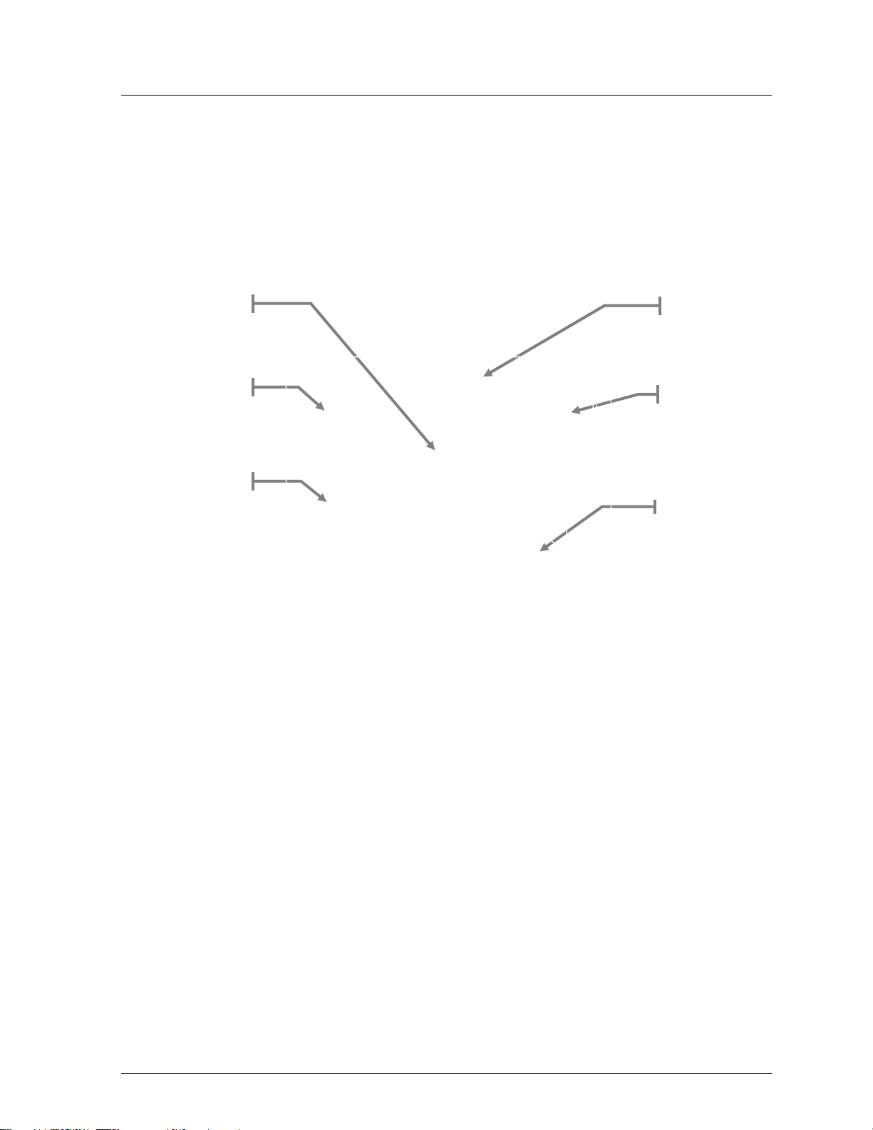
Product Overview
Power Out
Power In
NTRODUCTION
Fuseholder
DMX In
DMX Out
Microphone
Intimid ator™ Scan LED 2 00 User Manual (R ev. 0 2 a) Page 5 of 22
Page 6
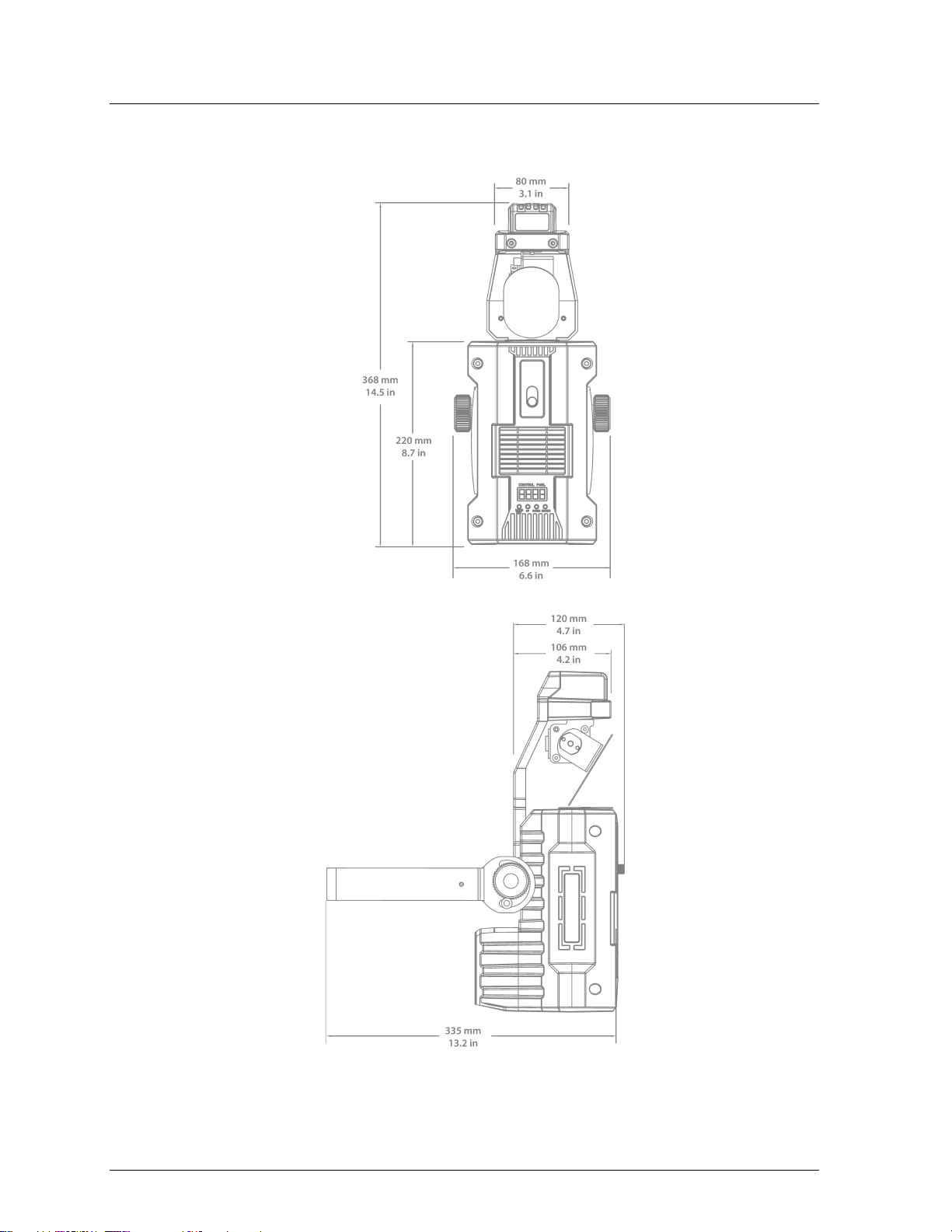
Product Dimensions
Page 6 of 22 Intimid ator™ Scan LED 2 00 User Manual (R ev. 0 2 a)
Page 7
3. S
AC Power
the back plate of the fixture or refer to the fixture’s specifications chart. A fixture’s
Fuse Replacement
ETUP
This product has an auto-ranging power supply and it can work with an input voltage
range of 100~240 VAC, 50/60 Hz.
To d eterm i n e th e pow er r equ i rem ent s for a par tic ul ar f ixt ur e, s ee th e l ab el a ff ixed to
listed current rating indicates its aver age current draw under normal conditions.
Always connect this product to a protected circuit (circuit breaker or fuse),
making sure that it has an appropriate electrical ground to avoid the risk of
electrocution or fire.
Never connect this product to a rheostat (variable resistor) or dimmer circuit,
even if the rheostat or dimmer channel ser ves only as a 0 to 100% switch.
Disconnect this product from the power outlet before replacing the fuse.
1) Disconnect the fixture from the power outlet.
2) With a Phillips #2 head s crewdr iver, unscr ew the fuse
holder cap from its housing.
3) Remove the blown fuse and replace it with a good
fuse of the same type and rating (F 3. 15 A @ 250 V).
4) Sc rew th e f use hol der cap back in its place and
reconnect power.
Always replace a blown fuse wi t h a good fuse of the same type and rating.
Intimid ator™ Scan LED 2 00 User Manual (R ev. 0 2 a) Page 7 of 22
Page 8

Power Linking
Fixture #1
Fixture #2
Fixture #3
To other fixtures
This fixture provides power linking via the Edi son outlet located in the bottom of th e
unit. Pl ease see t he dia gram below for further explanation.
Power Linking
Diagram
You can power link up t o 8 Intimidator™ Scan LED 200 units on 120 VAC.
The power linking diagram shown above corresponds to the North American
version of this product ONLY! If using this product in other markets, you must
consult with the local CHAUVET® distributor as power linking connect ors and
Page 8 of 22 Intimid ator™ Scan LED 2 00 User Manual (R ev. 0 2 a)
requirements may differ in your c ountry or region.
Page 9

Mounting
Orientation
Rigging
The bracket knobs allow for directional adjustment when aiming the fixture to the
The Intimidator™ Scan LED 200 may be mounted in any position, provided there is
adequate room for ventilation around it.
Before deciding on a location for this product, always make sure that it will be easy to
access the unit for maintenance and programming purposes.
Make sure that the structure or surface onto which you are mounting this product can
support its weig ht . Pl ea s e se e t h e Technical Specifications sec t i o n of t hi s ma nu al f or
weight information.
When mounting this product overhead, always use a safety cable. Mount the fixture
securely to a ri gging p oint, whether an elev ated platform or a tr uss.
When rigging this product onto a truss, you should use a mounting clamp of
appropriate weight capacity. The b rac ket has a 13 mm hole, wh ic h is a ppr opr ia te f or
this purpose.
When power linking multiple fixtures, you must always consider the length of the
power linking cable and mount the fixtures close e nough for the cabl e to reach them.
desired a ngle. Loosen or tighten the bracket knobs using only your bare hands. Using
tools could damage the knobs.
The double bracket yoke/mounting brackets also serve as floor supports or surface
mounting. When mounting this fixture on the floor, make sure that the fixture and its
cab les are away from people and vehi c l es.
Mounting Diagram
Bra cket
Adjustment Knob
Bra cket
Intimid ator™ Scan LED 2 00 User Manual (R ev. 0 2 a) Page 9 of 22
Page 10

4. O
Control Panel Operation
Press to find an operation mode
option
Press to sc roll u p t he list of
Press to sc roll d own the list of
options or to find a lower value
Press to activate a menu option or
a selected value
Menu Map
PERATION
To access the control panel functions, use the four buttons located under neath the
display.
Button Function
<MODE/ESC>
<UP>
or to back out of the current menu
options or to find a higher value
<DOWN>
<ENTER>
Menu Selection 1 Selecti on 2 Description
DM X A ddr ess d001~512 DMX starting address
SLAv Son Standalone: Slave receive mode
Standal one Mode
Pan Invert
Tilt Invert
Display In v er t
Personality
Reset rESt
Load Default LoAd
nStS SrUn Standalone: sound-active
nAFA FASt Standalone: fast
nASL SLoU Standalone: slow
PAn Normal pan
rPAn Pan invert
tit Normal tilt
rtit Tilt invert
dis Normal display
rdid Invert the display
8CH 8-channel personality
5CH 5-channel personality
Reset all m ot ors to c orr ec t an y errors
with motors misa ligning during operation
Load all settings back to the factory
default
Page 10 of 22 Intimid ator™ Scan LED 2 00 User Manual (R ev. 0 2 a)
Page 11

DMX Operation
Starting Address
When selecting a starting DMX address, always consider the number of DMX
If you are not familiar with the DMX protocol, you may refer to the “DMX Primer”
Set this p r oduct in DMX mode to control it with a DMX controller.
1) Connect this product to a suitable power outlet.
2) Turn this product on.
3) Connect a DMX cable from the DMX output of th e DMX control ler to the DMX
input socket of this product.
channels the selected DMX mode uses. If you choose a starting address that is too
high, you could restrict the access to some of t he fixture’s channels.
The Intimi dator™ Scan LED 200 uses up to 8 DMX channels in its 8-channel DMX
mode, which defines the highest configurable address to 505.
section in the “Technical Information” chapter.
To select the starting address, do the following:
1) Press <MODE/ESC> until d*** appears on the LED screen.
2) Using <UP> and <DOWN>, sel ect the starting address (001~512).
3) Press <ENTER>.
4) Press <MODE/ESC> until one of the DMX personalities appears on the LED
screen (8-CH, 5-CH).
5) Using <UP> and <DOWN>, sel ect the desired DMX personal i ty.
6) Press <ENTER>.
Only connect 32 fixtures to a single DMX daisy chain!
Intimid ator™ Scan LED 2 00 User Manual (R ev. 0 2 a) Page 11 of 22
Page 12

Standalone Operation
Master/Slave Mode (Sound-Active, Auto Mode)
Automatic-Slow
Access this mode via the control panel on the front of the fixture. Please see the
Automatic-Fast
Access this mode via the control panel on the front of the fixture. Please see the
Sound-Active
Access this via the control panel on the front of the fixture. Adjust the microphone
This mode allows a single unit, the master, to operate in one of the standalone
modes, while one or more fixtures, slaves, synchronize their responses to the master.
Master:
The master fixture may be set in any of the STANDALONE modes: sound-active,
fast, or slow.
Slave:
1) Press <MODE/ESC> until one of the standalone modes appe ars on the LED
screen (SLAu, nStS, nAFA, nASL).
2) Using <UP> and <DOWN>, select SLAu.
3) Press <ENTER>.
Only connect 32 fixtures to a single DMX daisy chain!
This fixture has a preprogrammed chase t hat will operate in a preprogrammed, slow
playback speed.
instructions below for further explanation.
1) Press <MODE/ESC> until one of the standalone modes appears on the LED
screen (SLAu, nStS, nAFA, nASL).
2) Using <UP> and <DOWN>, select nASL.
3) Press <ENTER>.
This fixture has a preprogrammed chase that will operate in a preprogrammed, fast
playback speed.
instructions below for further explanation.
1) Press <MODE/ESC> until one of the standalone modes appe ars on the LED
screen (SLAu, nStS, nAFA, nASL).
2) Using <UP> and <DOWN>, select nAFA.
3) Press <ENTER>.
This fixture has a preprogrammed, sound triggered chase.
sensiti vity from the control panel. Plea se see th e chart below for further explanation .
1) Press <MODE/ESC> until one of the standalone modes appe ars on the LED
screen (SLAu, nStS, nAFA, nASL).
2) Using <UP> and <DOWN>, select nStS.
3) Press <ENTER>.
The fixture will only respond to the low frequencies of the music (bass and
drums).
Page 12 of 22 Intimid ator™ Scan LED 2 00 User Manual (R ev. 0 2 a)
Page 13

Service Mode
Hidden Menu Ma p
his fixture has a hidden menu. The purpose of this menu is to adjust the home
T
position (electronic adjustment) of the attributes listed below.
Main Function Selection Instruction
P128 000~255 Adjustment for pan
t128 000~255 Adjustment for tilt
9128 000~255 Adjustment for the g ob o w heel
C128 000~255 Adjustment for the color wheel
H128 000~255 Adjustment for pan
Y128 000~255 Adjustment for tilt
Please see the instructions below to access this hidden menu:
1) Press < MODE/ESC > for at least 10 seconds.
2) Using <UP/DOWN>, enter the follow ing pass code: “2323”.
3) Press <UP> to change the blinking digit in ascending order, and press <DOWN>
to move on to the next digit.
4) Press <ENTER>.
This mode will be automatically terminated after 15 seconds of being idle.
Intimid ator™ Scan LED 2 00 User Manual (R ev. 0 2 a) Page 13 of 22
Page 14

DMX Channel Assignments and Values
8-Channel Mo de
1
Pan
2 Tilt
000 ó 255
0°~90°
000 ó 007
192 ó 255
Open (white)
Rotate counter-clockwise (slow ~ fast)
000 ó 003
216 ó 255
Closed
Open 5
Dimmer
000 ó 255
0%~100%
000 ó 007
192 ó 255
Open
Gobo scroll: Counter-clockwise rotation
\
Channel Function Value Setting
000 ó 255 0°~180°
3 Color
4 Shutter
6 Gobo Wheel
008 ó 015
016 ó 023
024 ó 031
032 ó 039
040 ó 047
048 ó 055
056 ó 063
064 ó 071
072 ó 079
080 ó 087
088 ó 095
096 ó 103
104 ó 111
112 ó 119
120 ó 127
128 ó 191
004 ó 007
008 ó 215
008 ó 015
016 ó 023
024 ó 031
032 ó 039
040 ó 047
048 ó 055
056 ó 063
064 ó 071
072 ó 079
080 ó 087
088 ó 095
096 ó 103
104 ó 111
112 ó 119
120 ó 127
128 ó 191
Dark Blue
Yellow
Pink
Green
Red
Blue
Salmon Pink
White/dark blue
Dark blue/yellow
Yellow/pink
Pink/green
Green/red
Red/blue
Blue/sal m on pink
Salmon pi nk /white
Rotate clockwise (slow ~ fast)
Open
Strob e (sl ow ~ f ast)
Gobo 1
Gobo 2
Gobo 3
Gobo 4
Gobo 5
Gobo 6
Gobo 7
Gobo 7 shake, fast to slow
Gobo 6 shake, fast to slow
Gobo 5 shake, fast to slow
Gobo 4 shake, fast to slow
Gobo 3 shake, fast to slow
Gobo 2 shake, (fast ó slow)
Gobo 1 shake, (fast ó slow)
Open
Gobo scroll: Clockw ise ro tation
Page 14 of 22 Intimid ator™ Scan LED 2 00 User Manual (R ev. 0 2 a)
Continues on the next page
Page 15

8-Channel
160 ó 255
No function
Mode (Cont.)
Continued from previous page
Channel Function Value Setting
7 Function
000 ó 007
008 ó 015
016 ó 023
024 ó 031
032 ó 039
040 ó 047
048 ó 055
056 ó 087
088 ó 095
096 ó 103
104 ó 111
112 ó 119
120 ó 127
128 ó 151
152 ó 159
No function
Pan/tilt move-in-black
Pan/tilt move-in-black (disable)
Color wh eel m ov e-in-black
Color wh eel m ov e-in-black (disabled)
Gobo wheel m ov e-in-black
Gobo wheel m ov e-in-black (disabled)
No Function
All movem en t m ov e-in-black (disabled)
Reset pan/ til t
No Function
Reset color wheel
Reset gobo wheel
No Function
Reset a ll
8 Movement Macros
000 ó 007
008 ó 023
024 ó 039
040 ó 055
056 ó 071
072 ó 087
088 ó 103
104 ó 119
120 ó 135
136 ó 151
152 ó 167
168 ó 183
184 ó 199
200 ó 215
216 ó 231
232 ó 247
248 ó 255
No function
Automatic 1
Automatic 2
Automatic 3
Automatic 4
Automatic 5
Automatic 6
Automatic 7
Automatic 8
Sound 1
Sound 2
Sound 3
Sound 4
Sound 5
Sound 6
Sound 7
Sound 8
Intimid ator™ Scan LED 2 00 User Manual (R ev. 0 2 a) Page 15 of 22
Page 16

5-Channel Mo de
\
1 Pan
000 ó 255
0°~180° 2
Tilt
000 ó 255
0°~90°
000 ó 007
192 ó 255
Open (white)
Rotate counter-clockwise (slow ~ fast)
000 ó 003
216 ó 255
Closed
Open
192 ó 255
Gobo scroll: Counter-clockwise rotation
Channel Function Value Setting
3 Color
4 Shutter
5 Gobo Wheel
008 ó 015
016 ó 023
024 ó 031
032 ó 039
040 ó 047
048 ó 055
056 ó 063
064 ó 071
072 ó 079
080 ó 087
088 ó 095
096 ó 103
104 ó 111
112 ó 119
120 ó 127
128 ó 191
004 ó 007
008 ó 215
000 ó 007
008 ó 015
016 ó 023
024 ó 031
032 ó 039
040 ó 047
048 ó 055
056 ó 063
064 ó 071
072 ó 079
080 ó 087
088 ó 095
096 ó 103
104 ó 111
112 ó 119
120 ó 127
128 ó 191
Dark Blue
Yellow
Pink
Green
Red
Blue
Salmon Pink
White/dark blue
Dark blue/yellow
Yellow/pink
Pink/green
Green/red
Red/blue
Blue/sal m on pink
Salmon pi nk /white
Rotate clockwise (slow ~ fast)
Open
Strob e (sl ow ~ f ast)
Open
Gobo 1
Gobo 2
Gobo 3
Gobo 4
Gobo 5
Gobo 6
Gobo 7
Gobo 7 shake, fast to slow
Gobo 6 shake, fast to slow
Gobo 5 shake, fast to slow
Gobo 4 shake, fast to slow
Gobo 3 shake, fast to slow
Gobo 2 shake, (fast ó slow)
Gobo 1 shake, (fast ó slow)
Open
Gobo scroll: Clockwise rotation
Page 16 of 22 Intimid ator™ Scan LED 2 00 User Manual (R ev. 0 2 a)
Page 17

5. TECHNICAL INFORMATION
General Maintenance
because you could
Dust build up reduces light output performance and can cause overheating. This can
lead to reducti on of the li ght s our ce’s life or mec hani cal w ear. To mai nt ai n o ptim um
performance and minimize wear , y ou shoul d clean your lighting fixtures at least twice
a month. However, be aware that usage and environmental conditions could be
con tribu ting f actors to increase the cleaning frequency.
To clean this fixture, follow the instructions below:
• Unplug the fixture from power.
• Wai t until the fix ture is cold.
• Use a vacuum ( or dry compressed ai r) and a s oft bru sh to remove dust collected
on the external surface/vents and reachable internal compon e nts.
• Clean the mirror and lens with a mild soap solution, ammonia-free glass cleaner,
or isopropyl alcohol.
• Apply t he sol ut ion directl y to a soft, lint free cotton cloth or a lens cleaning tissue.
• Softly drag any dirt or grime to the outside of the mirror and lens.
• Gently polish the mirror and lens until they are free of haze and lint .
• When clean ing the movable mirror, you should keep the contact with the mirror’s
surface to a minimum to avoid scratching or damaging it.
Alw ays dry the mirro r and lens ca refully after cleaning them.
Do not spin the cooling fan/fans using compressed air
dama ge it/them.
Intimid ator™ Scan LED 2 00 User Manual (R ev. 0 2 a) Page 17 of 22
Page 18

General Troubleshooting
If you still experience problems after trying the above solutions, contact
Symptom Possible Cause Possible Acti on
• Excessive load on the circuit • Make sure that the total load
does not exc eed 80% of the
Circuit breaker
or fuse keeps
blowing
• Short circuit along the
power lines
• No energy on power outlet • Ch eck power out let
breaker o r fuse nom inal
current
• Check the power lines and
power cords
• Change to another outlet
Product does not
power up
• Loose or damaged power
• Check the power cord
cord
• Blown fuse • R eplace blown fuse wi th a
good one of the same type
and rating
• Internal problem • Send product for repair
• Wrong starting addres s on
the fixture
• Set the cor rect st artin g
address on the fixture
• Use the right fader(s) on the
controller
• Wrong DMX personality on
the fixture
Fixture does not
respond to DMX
• Wrong pol arity setti ng on
the D MX controll er
• Loose or damaged DMX
cable
• Set the cor rect DMX
fixture’s personality
• Assign the faders
accordingly
• Change the signal polarity
on the controller
• Chec k the DM X cable
before the faulty unit
• Internal problem • Send product for repair
• Signal ca bles are not DM X
compatible
• Interference with AC or
radio signals
• Replace non DMX cables
with true DMX cables
• Keep DMX cables away
from AC wires or radio
equipment
Intermittent DMX
Problems
• DMX cable too long • Install an optically coupl ed
DMX amplif ier right before
the fixture with intermittent
problems
• Too many fixtures
connected
• Install an optically coupl ed
DMX amplif ier af ter uni t #32
• Terminator not connected • Install a terminator, as
indicat ed in the “DMX
Primer” section.
CHAUVET® Technical Support.
Page 18 of 22 Intimid ator™ Scan LED 2 00 User Manual (R ev. 0 2 a)
Page 19

Returns Procedure
and request a Return Merchandise Authorization (RMA) number
The user must clearly label the package with a Return Merchandise Authorization
will refuse any product returned without an RMA
or double-boxing is always a safe method to use.
Claims
The carrier is responsible for any damage incurred during shipping to this product or
report upon reception of the damaged merchandise. Failure to do so in a timely
For other issues such as missing components or parts, damage not related to
Contact In for m a tion
Fax: +44 (0)1773 511110
Email: tech@chauvetlighting.com
www.chauvetlighting.com
www.chauvetlighting.co.uk
The user must send the merchandise prepaid, in the original box, and with its original
packing and accessories. CHAUVET® will not issue call tags.
Call CHAUVET®
before shipping the fixture. Be prepared to provide the model number, serial number,
and a brief desc r iption of the cause for the return.
(RMA) number. CHAUVET®
number.
DO NOT write the RMA number directly on the box. Instead, write it on a
properly affixed label.
Once you have r eceiv ed the RMA number, please include the following information
on a piece of paper inside the box:
• Your name
• Your address
• Your phone number
• The RM A number
• A brief description of the problem
Be su r e to pack the fixture properly. Any shipping damage resulting from inadequat e
packaging will be t he customer’s responsibility. As a suggestion, proper UPS packing
CHAUVET® reserves the right to use its own discretion to repair or replace
returned product(s).
any part that shipped with it. Therefore, if the received merchandise appears to have
damages caused during shipping, the customer must submit the damage report and
any related claims with the carrier, not CHAUVET®. The cu stom er m ust s ubmi t t he
manner may invalidate the customer ’ s claim with the carrier.
shipping, or concealed damage, the customer must make claims to CHAUVET®
within seven (7) days of receiving th e merchandis e.
World Headquart ers
CHAUVET®
General Inform ation
Address: 5200 NW 108th Avenue
Sunrise, FL 33351
Voice: (954) 929-1115
Fax: (954) 929-5560
Toll free: (800) 76 2-1084
Technical Supp or t
Voice: (954) 929-1115 (Press 4)
Fax: (954) 756-8015
World Wide Web
United Kingdom & Ireland
CHAUVET® Europe Ltd.
General Inform ation
Address: Unit 1C
Brookhill Road Industrial Estate
Pinxton, Nottingham, UK
NG16 6NT
Voice: +44 (0)1773 511115
Technical Supp or t
Email: uktech@chauvetlighting.com
World Wide Web
Intimid ator™ Scan LED 2 00 User Manual (R ev. 0 2 a) Page 19 of 22
Page 20

DMX Primer
Starting Address
Fixture Linking (Daisy Chain)
Each fixture has a DMX In and a DMX Out
DMX cable in a sequential format called “daisy
the same DMX signals and they only respond to
However, it is important to notice that the
2nd DMX
The USITT DMX512-A data transmission protocol (DMX, from now on) is based on
the EIA-485 standard and it has 512 channels (001 to 512). Thi s sy stem requi res a
controller (DMX controller), one or more DMX compatible fixtures, and a DMX circuit
(also known as “DMX universe”) to link the fixtures to the controller.
Depending on their complexity and features, DMX compatible fixtures may require
from one to more than 30 DMX channels to operate. Some DMX fixtures have
multiple operation modes (also known as “personalities”), each with its own number
of channels and cont rollable parameters.
In the DMX system, the controller sends DMX data to each fixture based on the
fixture’s starting address. The starting address is the number of the DMX channel
(001 to 512) assigned to the fixture’s first control channel (Channel 1). When
assigning starting addresses to multiple fixtures, it is critical to ensur e that no st arting
address is already in use by anot her fixture to prevent channels from overlapping.
Otherwise, the a ffected fixtures ma y opera te errat ical ly.
For instance, a user has two DMX compatible fixtures. Fixt ure “A ” has four channels
and f ixt ur e “B ” has six channels. If the user configures the starting addr ess of fixture
“A” to “001”, channels 001 through 004 on the DMX controller will control fixture “A”.
This means that the us er should assign the starting address of fixture “B” to “ 005” or
higher. For a starting address of “005”, the DMX controller would use channels 005 to
010 to control fixture “B”.
It is poss ible t o contr ol mult ipl e fixtu res of the sam e type b y assi gnin g each o ne of
them t he s ame star t i ng address. In this case, all the fixtures would respond in unison
(synchr onized) to the signals from t he DMX controller.
DMX c ompat ible f ixt ures r eceive t he con tro l sig nals
from the DMX controller through the DMX cables.
connector. The f igure to the right illustrates how the
fixtures link to each other using multiple segments of
chain”.
The order in which the fixtures connect to the DMX
controller is irrelevant because all fixtures receive
them based on their individual starting addresses.
connections between fixtures should always be as
short and di rect as possible.
To ensure the integrity of the DMX signal, follow the
recommendations of the EIA-485 standar d:
• The maximum recommended cable length is 500 m (1,640 fee t).
• The maximum recommended numb er of fixtures on the same daisy chain is 32.
Connecting more than 32 fixtures on one daisy ch ai n without the use of a DMX
optically-isolated splitter m ay result in deterioration of the digital DM X signal.
DMX
Controller
1st DMX
Fixture
Fixture
To other
fixtures
Page 20 of 22 Intimid ator™ Scan LED 2 00 User Manual (R ev. 0 2 a)
Page 21

DMX Cabling
Type:
shielded, 2-conductor twisted pair
Maximum capacitance between conductors:
30 pF/ft
Maximum capacitance between conductor and shield:
55 pF/ft
Maximum resistance:
20 ohms/1000 ft
Nominal impedance:
100~14 0 oh ms
Each DMX cable m ust have a m ale XLR connec tor on one end and a female XLR
connector on the other end. The DMX protocol indicates that the XLR connectors
, ¼ W resistor connec ted to the wire side of pins 2 and 3, as
The DMX protocol requires using special data cables to accom modate for the high
speed digital signals it uses. Despite their apparent similarities, data cables are
electrically different from standard microphone cabl es because they can carry high
frequency digital signals and have better protection against electromagnetic
interference. You can purchase CHAUVET® certified DMX cables directly from a
dealer/distr ibutor or make your own DMX cable.
If you choose to make your own DMX cable, you must use a data-grade cable such
as the Belden 9841, which has the following electr ical c haracterist ics:
DMX Connectors
must have five pins. However, most lighting fixtures use t he 3-pi n XLR connector.
The pin assignm ent of the 3-pin and 5-pin XLR connectors in a DMX cable is as
follows:
Male Plu g
Signal 3-Pin
Common
Data -
Data +
Not us ed
Not us ed
You can use the above table to create a 3-pin/3-pin cable, a 5-pin/5-pin cable, or a 3pin to 5-pin adapter.
The DMX daisy chain uses a terminator to reduce signal transmission problems,
espec iall y with l ong ca bles. T he term inator consis ts of ei ther a 3 -pin or 5-pin XLR
male plug with a 120 Ω
shown below.
The t ermin ator plug c onnect s to th e DMX Out socket of th e last DMX fixt ure i n the
daisy chain.
Do not allow the common wire of the DMX cable to touch the fixture’s chassis
ground. This could cause a ground loop, which may affect your fixtures’
performance. Test all DMX cables with an ohmmeter to verify the correct
polarity of t he wires, and to make sure that they are not touching the shield or
each other.
5-Pin
1
2
3
1
2
3
4
5
5-Pin
1
2
3
4
5
Female Plug
3-Pin Signal
1
2
3
Common
Data -
Data +
Not us ed
Not us ed
Intimid ator™ Scan LED 2 00 User Manual (R ev. 0 2 a) Page 21 of 22
Page 22

6. TECHNICAL SPECIFICATIONS
Dimensions and Weight
Length
Width
Height
Weight
13.2 in (335 m m)
6.6 in (168 mm)
14.5 in (368 m m)
7.5 lbs (3.4 kg)
Note: Dimensions in inches rounded to the nearest decimal digit.
Power
Power Supply Type
Range
Voltage Selection
Switching (internal)
100~240 V, 50/60 Hz
Auto-ranging
Parameter
120 V, 60 Hz
230 V, 50 Hz
Consumption
68 W
67 W
Operating
1 A
0.5 A
Power linking
8 units
Power I / O
US/Worldwide
UK/Europe
Power input connector
IEC
IEC
Power output connector
Edison
Power Cord plug
Edison (US)
Local plug
Light Source
Type
Power
Lifespan
White LED
1 x 18 W
50,000 h ours
Photo Opti c
Parameter
Standard Lens
Beam angl e
15º
Scan Range
Parameter
Value
Pan
180°
Tilt
90º
Thermal
Maximum External Temp.
Cooling Syste m
104° F (40° C)
Fan
DMX
I/O Connectors
Connector Type
Channel Range
3-pin XLR
Sockets
5, 8
Ordering
Product Nam e
Item Code
Item Numb er
Intimidator™ Scan LED 200
08020174
INTIMIDATORSCANLED200
Illuminance @ 1 m 9,000 lx
Page 22 of 22 Intimid ator™ Scan LED 2 00 User Manual (R ev. 0 2 a)
 Loading...