

Page 1
User Manual
Page 2

TABLE OF CONTENTS
1. Before You Begin ...........................................................................................................3
What Is Included ......................................................................................................................... 3
Unpacking Instruc tions ................................................................................................................ 3
Claims ................................................................................................................................................. 3
Text Conventions ........................................................................................................................ 3
Symbols ...................................................................................................................................... 3
Disclaimer ................................................................................................................................... 3
Product at a Glance ..................................................................................................................... 4
Safety Notes ............................................................................................................................... 4
2. Introduction ....................................................................................................................5
Overview ..................................................................................................................................... 5
Dimensions ................................................................................................................................. 6
3. Setup ...............................................................................................................................7
AC Power .................................................................................................................................... 7
Fus e Repl acement ............................................................................................................................... 7
Power Linking ...................................................................................................................................... 8
Mounting ..................................................................................................................................... 9
Orientation ........................................................................................................................................... 9
Rigging ................................................................................................................................................ 9
4. Operation ......................................................................................................................10
Control Panel Operation ............................................................................................................ 10
Menu Map ................................................................................................................................. 10
Configuration ( DM X) .................................................................................................................. 10
Starting Address ................................................................................................................................ 10
DMX Channel Modes, Assignments, and Values ....................................................................... 11
4-Channel .......................................................................................................................................... 11
Configuration ( S tandalone) ........................................................................................................ 12
Manual Mode ..................................................................................................................................... 12
Display .............................................................................................................................................. 12
Res et Software .................................................................................................................................. 12
Load Factory Defaults ........................................................................................................................ 12
Infrared Remote Control ..................................................................................................................... 13
IRC Operation .................................................................................................................................... 13
Wi red Rem ote .................................................................................................................................... 14
Included Gobos ......................................................................................................................... 15
Changing Gobos ....................................................................................................................... 15
5. Technical Information ..................................................................................................16
Product Maintenanc e ................................................................................................................ 16
6. Techni cal Sp eci f ications ..............................................................................................17
Returns ..................................................................................................................................... 18
Contact Us ................................................................................................................................ 18
Page 2 of 18 Gobo Shot™ 50W IRC User Manual
Page 3
What Is
Unpacking
Instructions
and check the container t o make sure all the
included accessories) appear damaged from
mponents or parts, damage not related to shipping,
Text
Convention
Meaning
1—512
A range of values
50/60
A set of values of which only one can be chosen
Settings
A menu option not to be modified
Menu > Settings
A seq uence of menu opti ons to b e followed
<ENTER>
A key t o be pr essed on th e product’s control panel
ON
A value t o be entered or selected
Symbols
Critical installation, configuration, or operation informa tion. Not
damage to the product, or cause harm to the operator.
Disclaimer
are subject to change
ity for any errors or
and reserves the right to revise or recreate this manual at any time.
1. BEFORE YOU BEGIN
Included
Claims
Conventions
• Gobo Shot™ 50W IRC
• 10 Gobos
• Hanging bracket with mounting
hardware
Carefully unpack the product immediately
parts are in the package and ar e in good condition.
If the box or the contents (the product and
shipping, or show signs of mishandling, notify the carrier immediately, not CHAUVET®.
Failure to report damage to the carrier immediately may invalidate your claim. In
addition, keep the box and contents for inspection.
For ot her iss ues, such as missing co
or concealed damage, file a claim with CHAUVET® within 7 days of delivery.
Symbol Meaning
• Power cord
• Wired remote w i th RJ45 cable
• Warranty card
• Quick Reference G uide
The information and specifications contained in this User Manual
without notice. CHAUVET® assumes no responsibility or liabil
omissions,
Download the latest version from www.chauvetlighting.com.
© Copyright 2013 CHAUVET®. All rights reserved.
Electronically published by CHAUVET® in the U nited St ates of Am er ica.
Author Date Editor Date
A. Leon 07/19/13 T. Yeago 07/22/13
following these instructions may make the product not work, cause
Important installation or configuration information. The product
may not function correctly if this i nformation i s not us ed.
Useful information.
Gobo Shot™ 50W IRC User Manual Page 3 of 18
Page 4

Product at a
x
P
x
P
P
P
P
x
P
Safety Notes
Do not touch the product’s housing when operating because it may be very hot.
• Always make sure that the voltage of the outlet to which you are connecting the
Glance
Use on Dimmer
Out door Use
Sound-Activated
DMX
Master/Slave
These notes include important information about the mounting, usage, and maintenance
of this product; read before using the product.
• Always connect the product to a grounded circ uit to avoid the risk of electrocution.
• Always disconnect the product from the power source before cleaning or replacing
the fuse.
• Avo id di rect eye exp osure to the l ight sour ce whi le th e product is on.
• Make sure the power cord is not crimped or damaged.
• Never disconnect the product from power by p ul li ng or tugging on the c ord.
• If mounting the product overhead, always secure to a fastening d evice using a
safety cable.
• Make sure th ere are no flammable materials close t o the product when operating.
•
product is within the range stated on the decal or rear panel of the product.
• The product is for indoor us e only! (I P20) T o prevent risk of fire or shock, do n ot
expose the product to rain or moistu re.
• Always install the product in a location with adequate ventilation, at least 20 i n
(50 cm) from adjacent surfaces .
• Be su re that no ventilation slots on the product’s housing are blocked.
• Nev er co nnect the product to a dimmer.
• Make sure to repl ace the fus e w ith a noth er of t he same typ e and r ati ng.
• Nev er ca r ry the product fr om the power cord or an y moving pa rt. Alwa ys use the
hanging/mounting bracket.
• The maximum ambient temperat ure (Ta) is 104 ° F (40 °C). Do not operate the
product at higher temperatures.
• In the event of a serious operating problem, stop using the product immediately.
• Nev er tr y to repair the product. Repairs carr ie d out by unskilled people can lead to
damage or malfunction. Contact th e near est a uthorized techni cal assistan ce cen ter.
• This product is not intended for permanent installation.
Auto Programs
Auto-ranging Power Supply
Replaceable Fuse
User-Serviceable
• Keep this User Manual for future use. If you sell the product to anoth er user, be
sure to give this document t o the next o wner .
Page 4 of 18 Gobo Shot™ 50W IRC User Manual
Page 5
2. INTRODUCTION
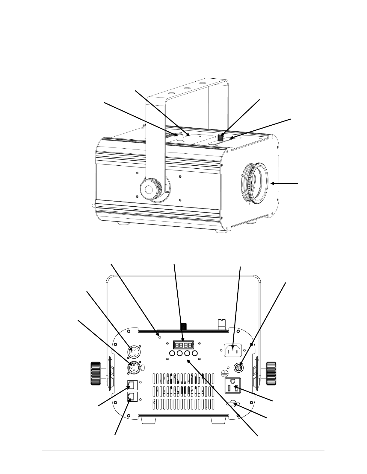
Overview
Back Panel View
Gobo Door
Thumbscrew
IRC Sensor
DMX In
DMX Out
Wired Remote In
Gobo Door
LED Display
Gel Frame Holder
Thumbscrew
Gel Frame
Holder
Focus
Power In
Fuse Holder
Power Out
Safety Loop
Wired Remote Out
Gobo Shot™ 50W IRC User Manual Page 5 of 18
Control Buttons
Page 6

Dimensions
10.2 in
258 mm
12.6 in
320 mm
12 in
306 mm
Page 6 of 18 Gobo Shot™ 50W IRC User Manual
Page 7

AC Power
ranging power supply and it can work with an
’s specifications chart. The listed current rating indicates the
(circuit breaker or fuse). Make
an appropriate electrical ground to avoid the risk of
a rheostat (variable resistor) or dimmer circuit, even
Fuse
3. SETUP
The G obo Shot™ 50W IRC has an aut oinput voltage range of 100~240 VAC, 50/60 Hz.
To determine the product’s power requirements (circuit breaker, power outlet, and
wiring), use the current value listed on the label affixed to the product’s bac k panel , or
refer to the product
product’s average current draw under normal cond itions.
Always connect the product to a protected circuit
sure the product has
electrocution or fire.
Never connect the product to
if the rheostat or dimmer channel serves only as a 0 to 100% switch.
Replacement
Disconnect the product from power before replacing the fuse.
1. Disconnect the product from power.
2. With a flat-head screwdriver, unscrew the fuse hol der cap
from the housing.
3. Remove the blown fuse.
4. Replace with a fuse of the sam e t ype and rating.
5. Sc rew t he fuse hol der cap back in place and reconnect
power.
Always replace a blown fuse with another of the same type and rating.
Gobo Shot™ 50W IRC User Manual Page 7 of 18
Page 8

Power Linking
provides power l inking via the Edison/IEC outlet located in the back of the
Power Linking
The power linking diagram shown above corresponds to the North American
in other markets, you must
consult with the local CHAUVET® distributor as power linking connectors and
1st Product
2nd Product
3rd Product
Additional Products
The product
unit.
Diagram
You can power link up to 9 Gobo Shot™ 50W IRC units on 120 VAC or up to 17
Gobo Shot™ 50W IRC units on 230 VAC.
version of the product ONLY! If using the product
requirements may differ in your country or region.
Page 8 of 18 Gobo Shot™ 50W IRC User Manual
Page 9

Mounting
, read and follow the safety recommendations indicated in
may be mounted in any position; however, make sure
Rigging
Mount the
appropriate
on the
Mounti ng C lam p
Safety Cable
Rubber Fe et
Hanging/Mounting
Bracket
Bracket
Knobs (2x)
Before mounting the product
the Safety Notes.
Orientation
The Gobo Shot™ 50W IRC
adequate ventilation is provided around the product.
• Before deciding on a location, always make sure there is easy access to the product
for maintenance and programming.
• Make su re th at th e str uctur e or surface onto which you are m ounting the product
can support the product’s weight (see the Technical Specifications
).
• When mounting the product overhead, always use a safety cable.
product securely to a rigging p oint , such as an elevated plat form or a tr uss.
• When rigging the product onto a truss, you should use a mounting clamp of
appropriate weight capacity. The bracket has 13-mm holes, which are
for this purpose.
• When power linking multiple products, you must al way s cons id er th e leng th of th e
power linking cable and mount the products close enough for th e cable to reach.
• The bracket adjustment knobs allow for directional adjustment when aiming the
product to the desired angle. Only loosen or tighten the bracket knobs manually.
Using t ools could damage the knobs.
• The rubber feet also serve as floor supports. When mounting the product
floor, make sure that the product and cables are away from people and vehicles.
Mounting Diagram
Adjustment
Gobo Shot™ 50W IRC User Manual Page 9 of 18
Page 10

Control Panel
Operation
underneath the
<DOWN>
Menu Map
Main Function
Programming Levels
Description
diNN
L000—L255
SHut
S000—S100
Shutter (0—20 Hz)
Load
LoAd
Configuration
choose a starting address that is too high, you could
DMX mode,
4. OPERATION
To access the control panel functions, use the four buttons located
display.
Button Function
<MENU> Selects an operation mode or backs out of the current menu option
<UP> Scrolls u p the list of options or selects a higher value
Scrolls down the list of opti ons or selects a lower value
<ENTER> Activates a menu opt ion or a selected value
DMX Address d001—d512 Selects th e D M X starti ng address
StoP Gobo rotati on, stop
CU Gobo rotation, rainbow effect
CCU G obo ro tation, reverse rain bow ef fect
Dimme r (0—100%)
Manual Mode nAn
Gobo
GoSP 000—255 Gobo rotation speed
Starting Add ress
(DMX)
Display diS
Reset rESt Res ets fixt ure
Set the product in DMX mode t o control with a D M X cont rol ler.
1. Connect the product to a suitable po w er outlet .
2. Connect a DMX cabl e from the DMX output of the DMX cont roll er to the DMX input
socket on the product.
Wh en selec ting a s tart ing DMX addres s, alw ays co nsider the num ber of DMX cha nnels
the selected DMX mo de uses. If you
restrict t he ac cess t o som e of t he product’s channels.
The Gobo Shot™ 50W IRC uses up to 4 DMX channels in its 4-channel
which defi nes th e highest c onfigurable address t o 509.
If unfamiliar with DMX, downloa d the D M X Primer fr om www.chauvetlighting.com.
To s elect the starting address, do the following:
1. Press <MENU> repeatedl y until d001—d512 shows on the display.
2. Press <ENTER>.
3. Use <UP> or <DOWN> to sel ect t he st arting addres s.
4. Press <ENTER>.
diS Normal display
rdiS Rev erse d isplay
Loads factory defaults
Page 10 of 18 Gobo Shot™ 50W IRC User Manual
Page 11

DMX Channel Modes, Assignments, and Values
1
Dimmer
000 ó 255
0—100%
000 ó 003
216 ó 255
Closed
Open
000 ó 063
192 ó 255
Stop
Reverse rotation
4 Gobo Rotation Speed
000 ó 255
Gobo speed (slow to fast)
4-Channel
Channel Function Value Setting
2 Shutter
3 Gobo Rotation
004 ó 007
008 ó 215
064 ó 127
128 ó 191
Open
Strob e, wit h inc reasing s peed (0—20 Hz)
Rotation
Stop
Gobo Shot™ 50W IRC User Manual Page 11 of 18
Page 12

Configuration
(Standalone)
to a DMX string
s in standalone mode may transmit DM X
Load Factory
Set the product in the standalone Manual mode to control without a DMX controller.
• Connect the product to a suitable power outlet.
Never connect a product that is operating in a s tandalone mode
connected to a DMX controller. Product
signals that could interfere with the DMX signals from the controller.
Manual Mode
To enable the Manual mode, do the foll owing:
1. Press <MENU> repeatedl y until nAn shows on the display.
2. Press <ENTER> and Gobo, GoSP, diNN, or SHut show on the display.
3. Use <UP> or <DOWN> to select the desired option as follows.
To s elect from the g obo r otat ion op t ions:
1. Select Gobo a nd pres s <ENTER>.
2. Use <UP> or <DOWN> to select CU ( rainbow effect), CCU (rev ers e rai nbow effec t),
or StoP (stop).
3. Press <ENTER>.
To select the gobo rotation speed:
1. Select GoSP an d press <ENTER>.
2. Use <UP> or <DOWN> to select 000—255.
3. Press <ENTER>.
For dimmer control:
1. Select diNN and press <ENTER>.
2. Use <UP> or <DOWN> to select L000—L255 (0—100%).
3. Press <ENTER>.
To s et the shutter speed:
1. Select SHut and press <ENTER>.
2. Use <UP> or <DOWN> to select S000—S100 (0—20 Hz).
3. Press <ENTER>.
Display
You are able to flip the display for easy readability in any mounting situation.
To s elect your displa y angl e:
1. Press <MENU> repeatedly u ntil diS (normal display) or rdiS (inverted display)
2. Use <UP> or <DOWN> to select the des ir ed displa y .
3. Press <ENTER>.
Reset Software
To reset t he so f tware in the G obo Shot™ 50W IRC, do the following:
1. Press <MENU> repeatedly until rESt shows on the display.
2. Press <ENTER>.
To load the factory default settings in the Gobo Shot™ 50W IRC, do t he followin g:
Defaults
1. Press <MENU> repeatedly until LoAd shows on the display.
2. Press <ENTER>.
Page 12 of 18 Gobo Shot™ 50W IRC User Manual
shows on the display.
Page 13

Infrared Remote
Control
IRC Operation
The following IRC buttons are used with the Gobo Shot™ 50W IRC:
The G obo Shot™ 50W IRC is compatible with the I nfr ared Rem ote Co ntr ol (I RC) from
CHAUVET®.
Note: Make sure to point the IRC directly at the receiver.
• <BLACKOUT> - turns LED on/off
• <STROBE> - strobing (0–20 H z)
• <SPEED> - gobo rotation
Note: Af ter pres sing th e <SPEED> button, CU s hows on the d ispla y until
you i ncreas e or decrease th e gobo rotatio n speed (see bel ow).
• <%> - master dimmer
• <MANUAL> - stops rotation
• <FADE/SNAP> - select s clockwise/cou nter-clockwise
• <+> (plus) - incr eases effect
- to increase gobo rotation, pre ss the <SPEED> button first (settings 0–255)
- to increase strobing, press the <STROBE> button first (settings S000–S100)
- to increase dimming, press the <%> button first (settings L000–L255)
• <-> (minus) - decreases ef fect
- to decrease gobo rotation, press the SPEED button first (settings 0–255)
- to decrease strobing, press the STROBE button first (settings S000–S100)
- to decrease dimming, press the % button first (settings L000–L255)
• <0>–<9> - preset rotation speeds 0— 9 (slow to fast)
The buttons on the IRC not li sted above ar e r eserved for future use with
the Gobo Shot™ 50W IRC .
Gobo Shot™ 50W IRC User Manual Page 13 of 18
Page 14

back of the
Wired Remote
To operate the Gobo Shot™ 50W IRC with the included wired remote, follow
the instructions below:
Plug the wired remote into the Wired Remote In port on the
project or , and us e th e remot e as f ollo ws:
• To control the gobo’s rotation speed, turn the ROTATION SPEED knob to
the desir ed speed ( slow to fast).
• To control the direction of the gobo’s rotation, flip the DIRECTION switch to
either CCW (counter-clockwise) or CW (clockwi se).
• To control the power to the Gobo Sho t™ 50W IRC, flip the POWER switch
to either ON or OFF.
The Wired Remote In/Out ports allow one Gobo Shot™ 50W IRC to remotely
control the actions of another Gobo Shot™ 50W IRC without the need of an
additional wired remote. Using a standard RJ45 (network) cable, connect
the projector with the wired remote from its Wired Remote Out port to the
Wired Remote In port of the other projector. Gobo Shot™ 50W IRC
projectors configured in this manner operate in unison.
Page 14 of 18 Gobo Shot™ 50W IRC User Manual
Page 15

Included Gobos
Changing
Gobo Replacement Diagram
Gobos
Gobo
To change the gobos in the Gobo Shot™ 50W IRC, do the following:
1. Turn off and disconnect the product from pow er.
2. Place the product on a flat, level surface.
3. Loosen the gobo door thumbscrew and pull open the hinged gobo door.
4. Remove the expansion ring that holds the gobo in place and rem ove the gobo from
the gobo holder.
5. Insert a new gobo and hold it in place with the expansion ring.
6. Close the gobo door.
7. Tighten t he gobo door thumbscrew.
Gobo Holder
Expansion Ring
Gobo Shot™ 50W IRC User Manual Page 15 of 18
Page 16

Product
up reduces light output performance and can cause overheating. This can
lead to reduction of the light source’s life and mechanical wear. To maintain optimum
surfaces carefully after
5. TECHNICAL INFORMATION
Dust build-
Maintenance
performance and minimize wear, clean the product at least twice a mont h. However ,
usage and envi r onmental conditions contr ibute to increa sed cleaning frequency.
To clean the product, follow the instructions be low:
• Unplug the product from po w er.
• Wait until the product is at room temperature.
• Use a vacuum (or dry compressed air) and a sof t brush to remov e dust collected on
the external surface/vents and reachable internal components.
• Clean all external optics and glass/transparent surface s wi th a mild soap solution,
ammonia-free glass cleaner, or isopropyl alcohol.
• Apply the solution directly to a soft, lint-free c otton cloth or a lens cleaning tissue.
• Softly wipe any dirt or grime to the outside edges of the external optics or
glass/transparent surface.
• Gently poli sh the external optics and glass/transparent surfaces until they are free of
haze and lint.
Always dry the external optics and glass/transparent
cleaning them.
Do not spin the cooli ng fan using compressed air because you could dam age it.
Page 16 of 18 Gobo Shot™ 50W IRC User Manual
Page 17

Dimensions and
Length
Width
Height
Weight
12 in (306 mm)
12.6 in (320 mm)
10.2 in (258 mm)
10.8 lb (5 kg)
Note: Dimensions in inches rounded to the nearest decimal digit.
Power
Power Supply Type
Range
Voltage Selection
Switching (internal)
100~240 V, 50/60 Hz
Auto-ranging
Parameter
120 V, 60 Hz
230 V, 50 Hz
Consumption
102 W
109 W
Operating current
0.8 A
0.4 A
Power linking current (units)
8 A (9 units)
8 A (17 units)
Fuse
F 3 A, 250 V
F 3 A, 250 V
Power I / O
US/Worldwide
UK/Europe
Power input connector
IEC
IEC
Power output connector
Edison
IEC
Power Cord plug
Edison (US)
Local plug
Light Source
Type
Power
Lifespan
LED
50 W
50,000 h ours
Color
Quantity
Current
White 1 2 A
Photo Optic
Parameter
Illuminance @ 2 m
2937 lx
Beam angl e
26º
Stro be r ate
0—20 Hz
53 mm outsi d e
1 mm max thickness (size D)
Thermal
Maximum External Temp.
Cooling Syste m
104 °F (40 °C)
Fan-cooled
DMX
I/O Connectors
Connector Type
Channel Range
3-pin XLR
Sockets
4
Ordering
Product Name
Item Code
UPC Number
Gobo Shot™ 50W IRC
03050718
781462210663
6. TECHNICAL SPECIFICATIONS
Weight
Gobo size
40 mm image
Gobo Shot™ 50W IRC User Manual Page 17 of 18
Page 18

s to
Returns
Support office and request a Return
. Be prepared to
cause for the
You must send the merchandise prepaid, in its original box, and with its original packing
the following information on a piece of paper
properly. Any shi pping damage resulting from inadequate
reserves the right to use its own discretion to repair or replace
Contact Us
Fax: +44 ( 0)1773 511110
Email: tech@chauvetlighting.com
www.chauvetlighting.com
www.chauvetlighting.co.uk
To return a product or request support:
• In the U.S., contact CHAUVET® World H eadquarters (see b elow ) .
• In the UK or Ireland, contact CHAUVET® Europ e Ltd. (see below ).
• In any other country, DO NOT contact CHAUVET®. Contact your distributor. See
www.chauvetlighting.com
for distributors outside the U.S., United Kingdom, or
Ireland.
If you live outside the U.S., United Kingdom, or Ireland, contact your distributor of
record and follow their instructions on how to return CHAUVET® product
them. Visit our website for contact details.
Call the corresponding CHAUVET® Technical
Merchandise Authorization (RMA) number before shipping the product
provide the model number, serial number, and a brief description of the
return.
and accessories. CHAUVET® will not issue call tags.
Clearly label the package with the RMA number. CHAUVET® will refuse any product
returned without an RMA number.
Write the RMA number on a properly affixed label. DO NO T wr i t e th e RM A number
directly on the box.
Before sending the product, clea rly wr ite
and place it inside the box:
• Your name
• Your address
• Your phone number
• RMA number
• A brief description of the problem
Be su re to p ack th e product
packaging will be your responsibility. FedEx packing or double-boxing are
recommended.
CHAUVET®
returned product(s).
World Headquart ers
CHAUVET®
General Inform ation
Address: 5200 NW 108th Avenue
Sunrise, FL 33351
Voice: (954) 577-4455
Fax: (954) 929-5560
Toll free: (800) 762-1084
Technical Support
Voice: (954) 577-4455 (Press 4)
Fax: (954) 756-8015
United Kingdom & Ireland
CHAUVET® Europe Ltd.
General Inform ation
Address: Unit 1C
Brookhill Road Industrial Estate
Pinxton, Nottingham, UK
NG16 6NT
Voice: +44 (0)1773 511115
Technical Support
Email: uktech@chauvetlighting.com
World Wide Web
Page 18 of 18 Gobo Shot™ 50W IRC User Manual
World Wide Web
 Loading...