

Page 1
User Manual
*Lens tubes
sold separately
Page 2

Edition Notes
The OVATION™ E-190WW User Manual Rev. 3 covers the description, safety
OVATION™
User Manual
Trademarks
CHAUVET® is a r egistered trademark of CH AUVET & Sons Inc. (d/b/a C HAUVET® or
the
) are owned or licensed by
product names, logos, brands, company names, and other
trademarks featured or referred to within this document are the property of their
Copyright Notice
CHAUVET® ow ns the c o nt ent of this User Manual in its entiret y, includ ing but not lim ited
Manual Use
CHAUVET® authori zes its c ustomers to download a nd print th is m anual for prof essional
sage, copy, storage,
se
Document Printing
For better results, print th is document in c olor, on lette r size paper (8. 5 x 11 in), doub lesided. If using A4 paper (210 x 297 mm), configure your printer to scale the content
Intended Audience
Any person in charge of installing, operating, and/or maintaining this product should
Disclaimer
CHAUVET® believes that the information contained in this manual is accurate in all
notify any person or
Document Revision
The OVATION™ E-190WW User Manual Rev. 3 supersedes all previous ver sio ns of this
Go to
Author
Date
Editor
Date
A. Leon
03/19/14
D. Couppe
03/19/14
Edition Notes
precautions, installat ion, programming, operation, and maintena nce of the
E-190WW. CHAUVET ® released this edition of the OVATION™ E-190WW
in March 2014.
Chauvet). The CHAUVET ® logo in its entiret y including the CHAUVET® name and
dotted triangle, and all other tradem arks in this manual pertain ing to services, products ,
or marketing statements (example: It’s Green Thinking™
CHAUVET®. Any other
respective trademark holders.
to pictures, logos, trademarks, and resources.
© Copyright 2014 CHAUVET®. All rights reserved.
Electronically published by CHAUVET® in the United States of America.
information purposes only. CHAUVET® expressly prohibits the u
distribution, m odification, or printing of this manual or its content f or any other purpo
without written consent from CHAUVET®.
accordingly.
completely read through the guide that shipped w ith the produc t, as well as this m anual,
before installing, operating, or maintaining this product.
respects. However, CH AUVET® assumes no res ponsibility for any errors or omis sions
in this document. CHAUVET® reserves the right to revise and m ake changes to the
content of this document without obligation that CHAUVET®
company of such revision or changes. This does not in any way constitute a
commitment by CHAUVET® to make such changes. CH AUVET® may issue a revision
of this manual or a new edition to incorporate such changes.
manual. Discard any older versions of this manual and repl ace with this version.
www.chauvetprofessional.com for the latest version.
OVATION™ E-190WW User Manual Rev. 3
Page 3

Table of Contents
Table of Contents
1. Before You Begin ...................................................................................................................................... 1
What is Included ........................................................................................................................................................... 1
Claims .......................................................................................................................................................................................... 1
Manual Conventions .................................................................................................................................................................... 1
Symbols ....................................................................................................................................................................................... 1
Product at a Glance ...................................................................................................................................................... 2
Safety Notes ................................................................................................................................................................. 2
Personal Safety ............................................................................................................................................................................ 2
Mounting and Rigging .................................................................................................................................................................. 2
Power and Wiring ......................................................................................................................................................................... 2
Operation ..................................................................................................................................................................................... 2
Expected LED Lifespan ................................................................................................................................................ 2
2. Introduction ............................................................................................................................................... 3
Description .................................................................................................................................................................... 3
Features ........................................................................................................................................................................ 3
Lens Tube ..................................................................................................................................................................... 3
Overview ....................................................................................................................................................................... 4
Dimensions ................................................................................................................................................................... 5
3. Setup .......................................................................................................................................................... 6
AC Power ...................................................................................................................................................................... 6
AC Plug ........................................................................................................................................................................................ 6
Fuse Replacement ....................................................................................................................................................................... 6
..................................................................................................................................................................................................... 6
Power Linking ............................................................................................................................................................... 7
DMX Linking.................................................................................................................................................................. 7
DMX Modes ................................................................................................................................................................................. 7
Master/Slave Connectivity ............................................................................................................................................................ 7
Mounting ....................................................................................................................................................................... 8
Orientation ................................................................................................................................................................................... 8
Rigging ......................................................................................................................................................................................... 8
4. Operation ................................................................................................................................................... 9
Control Panel Description ............................................................................................................................................. 9
Control Options ............................................................................................................................................................. 9
Programming ................................................................................................................................................................ 9
Menu Map ................................................................................................................................................................... 10
DMX Values ................................................................................................................................................................ 11
DMX Personality ........................................................................................................................................................................ 11
DMX Control............................................................................................................................................................................... 11
Loss of Signal Setting ................................................................................................................................................................ 11
Dimmer - Menu Control .............................................................................................................................................................. 12
Dimmer Speeds ......................................................................................................................................................................... 12
Dimmer Curves .......................................................................................................................................................................... 12
Control Panel Lock ..................................................................................................................................................................... 12
Passcode ................................................................................................................................................................................... 12
Menu Access Lock ..................................................................................................................................................................... 12
Reset .......................................................................................................................................................................................... 13
Performance Power Output Options .......................................................................................................................................... 13
Manual Beam Focus Control ...................................................................................................................................................... 13
Rotating the Barrel Assembly ..................................................................................................................................................... 13
Master/Slave Mode .................................................................................................................................................................... 14
Drop-In Iris Slot .......................................................................................................................................................................... 14
OVATION™ E-190WW User Manual Rev. 3 -i-
Page 4

Table of Contents
5. Technical Information ............................................................................................................................. 15
Product Maintenance .................................................................................................................................................. 15
Cleaning the Reflector Housing Lens ......................................................................................................................................... 15
Technical Specifications ............................................................................................................................................. 16
Returns ....................................................................................................................................................................... 17
Contact Us .................................................................................................................................................................. 17
-ii- OVATION™ E-190WW User Manual Rev. 3
Page 5
1. Before You Begin
What is Included
• OVATION™ E-190WW
• Quick Reference Guide
Claims
Carefully unpack the pr oduct immediately and check the box to m ake sure all the parts
If the box or the contents (t he product and include d accessories ) appear damaged f rom
shipping or show signs of m ishandling, notify the carrier immediatel y, not CHAUVET®.
your claim. In
Manual Conventions
Convention
Meaning
1–512
A range of values in the text
50/60
A set of mutually exclusive values in the text
<SET>
A button on the product’s control panel
Settings
A product function or a menu option
MENU>Settings
A sequence of menu options
1–10
A range of menu values from which to choose in a menu
Yes/No
A set of two mutually exclusive menu options in a menu
ON
A unique value to be entered or selected in a menu
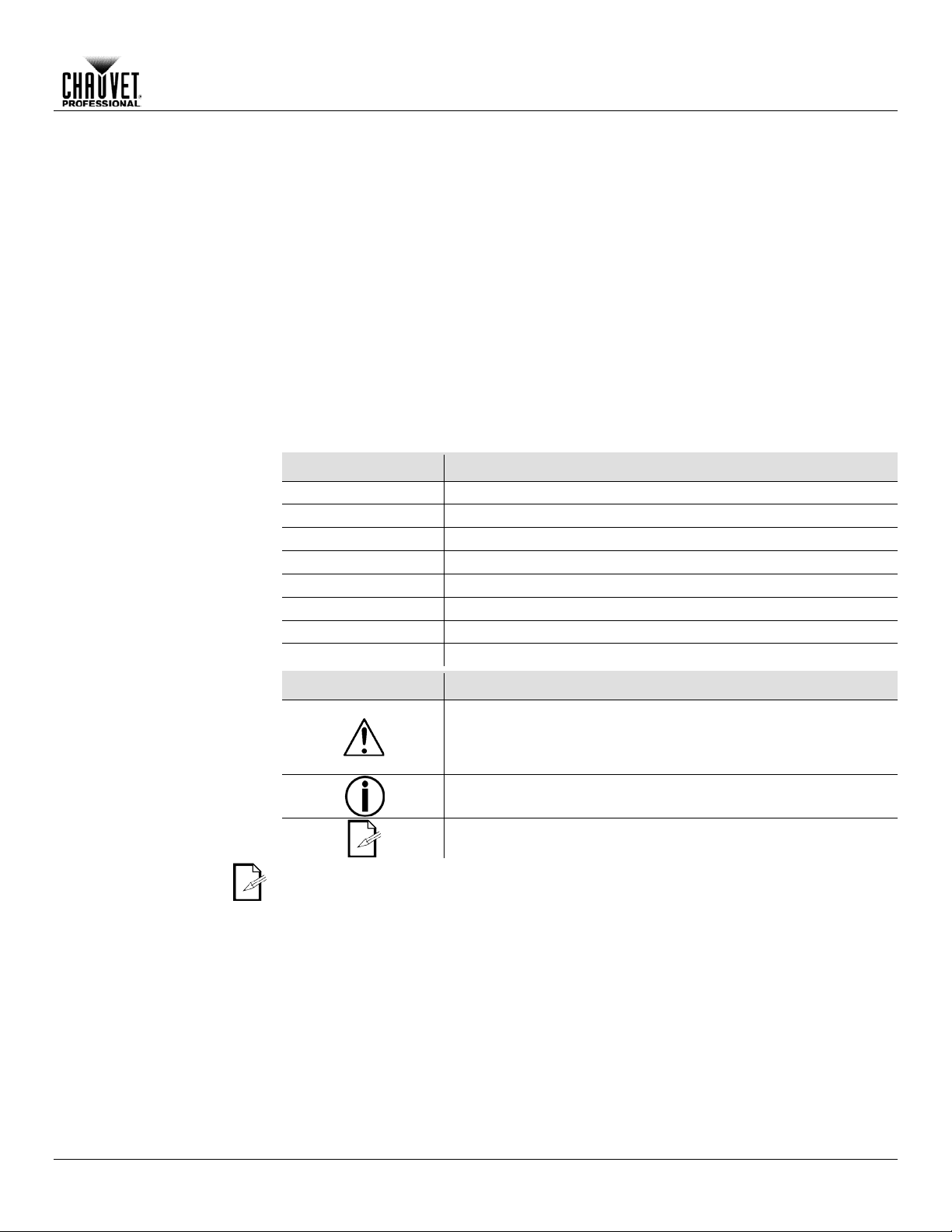
Symbols
Critical installation, configuration, or operation information.
operator.
The term “DMX” used throughout this manual refers to the USITT DMX512-A
digital data transmission protocol.
• Neutrik® powerCON® power cord
• Gel Frame (6.25 in/159 mm accessories)
• Safety Cable
• Warranty Card
are in the package and are in good condition.
Failure to report damage to the carrier immediately may invalidate
addition, keep the box and contents for inspection.
For other issues, s uch as miss ing components or par ts, dam age not relat ed to s hipping,
or concealed damage, file a claim with CHAUVET® within 7 days of delivery.
Before You Begin
Symbols Meaning
Failure to comply with this information may cause the product not
to work, damage third-party equipment, or cause harm to the
Important installation or configuration information. Failure to
comply with this information may keep the product from working.
Useful information.
OVATION™ E-190WW User Manual Rev. 3 -1-
Page 6
Product at a Glance
x
x
x
Auto-Ranging Power
Supply
P
x
P
P
x
P
x
Safety Notes
Read all the following Safety Notes before working with this product. These notes
This product contains no user-serviceable parts. Any reference to servicing in
this User Manual will only apply to properly trained CHAUVET® certified
All applicable local codes and regulations apply to proper installation of this
Personal Safety
• Avoid direct eye exposure to the light source while the product is on.
• Do not touch this product’s housing during operation because it may be very hot.
Mounting and
• This product is for indoor use only! (IP20) To prevent risk of fire or shock, do not
loose, the barrel assembly may inadvertently separate from the reflector housing.
Power and Wiring
• Always make sure you are connecting this product to the proper voltage in
• Never disconnect this product by pulling or tugging on the power cable.
Operation
• Do not operate this product if you see damage on the housing, lenses, or cables.
• In case of a serious operating problem, stop using this product immediately!
In the unlikely event that your CHAUVET® product may require service, contact
Expected LED
LEDs gradually dec line in brightness o ver time, mostly becaus e of heat. Packag ed in
Before You Begin
Rigging
Use on Dimmer
Outdoor Use
Sound-Active
DMX
Master/Slave
include important information about the installation, usage, and maintenance of this
product.
technicians. Do not open the housing or attempt any repairs.
product.
• Always disconnect this product from its power source before servicing.
• Always connect this product to a grounded circuit to avoid the risk of electrocution.
expose this product to rain or moisture.
• Mount this product in a location with adequate ventilation, at least 20 in (50 cm)
from adjacent surfaces.
• Make sure there are no flammable materials close to this product while it is
operating.
• When hanging this product, always secure to a fastening device using a safety
cable (included).
• Use caution when loosening the barrel rotation knobs. If these knobs become too
Auto Programs
Replaceable Fuse
User-Serviceable
Duty Cycle
accordance with the specifications in this manual or on the product’s specification
label.
• Never connect this product to a dimmer pack or rheostat.
Have the damaged parts replaced by an authorized technician at once.
• Do not cover the ventilation slots when operating to avoid internal overheating .
• The maximum ambient temperature is 113 °F (45 °C). Do not operate this product
at a higher temperature.
CHAUVET® Technical Support.
Lifespan
-2- OVATION™ E-190WW User Manual Rev. 3
clusters, LEDs exhibit higher operating temperatures than in ideal, single-LED
conditions. For this re ason, using clustered L EDs at their fullest intensity sign ificantly
reduces the LEDs’ lifespan. Under normal conditions, this lifespan can be 40,000 to
50,000 hours. If extending this lifespan is vital, lower the operating temperature by
improving the ventilation around the product and reduc ing the ambient temperature to
an optimal operating range. In addition, limiting the over all projec ti on in tens ity may also
help to extend the LEDs’ lifespan.
Page 7

2. Introduction
Description
The OVATION™ E-190WW delivers an excellent white light with a warm color
It also features standar d beam shaping s hutters, a
gobo/effect slot and lens barrels that are interchangeable with other popular ERS
es that intermix well with
Features
• Warm white LED ERS-style lighting product
• 3- and 5-pin XLR data input and output connectors
Lens Tube
The following lens tubes are available for purchase.
Introduction
temperature and a beautif ul flat field.
fixtures. Selectable dimming curves ensure smooth fading cu
the output of conventional theatre ellipsoidals.
• Operating modes:
• 1-channel (UNO): dimmer control
• 2-channel (DOS): dimmer and fine dimmer control
• 3-channel (STD.P): dimmer, fine dimmer, and strobe control
• Accessory slot for motorized gobo devices and iris unit
• 16-bit dimming for smooth fades
• Flat, even field of light
• Comes with standard pattern slot for glass or steel patterns and soft focus diffuser
• Virtually silent operation
• Works perfectly with industry standard lens tubes
• Simple and complex DMX channel profiles for programming versatility
• 19°
• 26°
• 36°
• 50°
Do not operate the OVATION™ E-190WW without a lens tube installed.
OVATION™ E-190WW User Manual Rev. 3 -3-
Page 8

Rear View
Side View
powerCON®
Output
Menu Buttons
3- and 5-pin DMX In
3- and 5-pin DMX Out
Fuse Holder
Gel Frame
Display
Handle
Framing Shutter
Barrel
Knobs
Reflector
Drop-in
Iris Slot
(A
B
patterns,
Introduction
Overview
Rotation
powerCON®
Input
(x 4)
Housing
Pattern Holder Slot
-size holder for 3-in patterns
-size holder for 2.5-in and 2.75-in
Barrel
Assembly
sold separately)
Beam Focus Knobs
Holder
Lens Tube
(sold separately)
-4- OVATION™ E-190WW User Manual Rev. 3
Page 9

Dimensions
6.7 in
171 mm
Side View
Top View
15 in
380 mm
7.1 in
180 mm
20.9 in
530 mm
8.7 in
222 mm
25.4 in
645 mm
12 in
305 mm
Introduction
6.25 in
159 mm
6.9 in
174 mm
OVATION™ E-190WW User Manual Rev. 3 -5-
Page 10

AC Power
Each OVATION™ E-190WW has an auto-r anging po wer suppl y that works with an inp ut
voltage range of 100~240 VAC, 50/60 Hz. To determine the power requirements for
, refer to the label affixed to the pro duct. You ca n also ref er
The listed current r ating indicates the maximum current draw during normal oper ation.
®
Always connect this product to a protected circuit with an appropriate electrical
Never connect this product to a rheostat (variable resistor) or dimmer circuit, even
AC Plug
The OVATION™ E-190WW comes with a power input cord terminated with a Neutrik®
nd (U.S. m arket).
AC Live
Black
Brown
Yellow or Brass
AC Neutral
White
Blue
Silver
AC Ground
Green/Yellow
Green/Yellow
Green
Fuse Replacement
1. Disconnect this product from power.
Setup
3. Setup
each OVATION™ E-190WW
to the Technical Specif icati ons chart in this manual.
For more information, you may download Sizing Circuit Bre akers from the CHAUVET
website www.chauvetpro.com.
ground to avoid the risk of electrocution or fire.
if the rheostat or dimmer channel serves only as a 0 to 100% switch.
powerCON® A connector on one end and an Ediso n plug on the other e
If the power input cord tha t came with your pro duct has no plug, or if you need to c hange
the Edison plu g , u se th e t abl e be low to wire the new plug to th e pow e r inp u t co r d.
Connection Wire (U.S.) Wire (Europe) Screw Color
Make sure to disconnect the produc t’s power cord before replacing a blown fuse.
2. Using a Phillips #2 head screwdriver, unscrew the fuse holder
cap from the housing.
3. Remove the blown fuse and replace with another fuse of the
same type and rating (T 3.15 A, 250 V).
4. Screw the fuse holder cap back in place and reconnect power.
Always replace the blown fuse with another of the same type and rating.
-6- OVATION™ E-190WW User Manual Rev. 3
Page 11

Setup
Power Linking
The OVATION™ E-190WW supports power linking. Yo u can power link up to 4 units on
cord. This pro duct does not
DMX Linking
You can link the OVATION™ E-190WW to a DMX controller using a standard DMX
DMX Modes
The OVATION™ E-190WW uses the standard DMX data connection for the 1-, 2- and
modes.
Master/Slave
The Master/Slave mode allo ws a single OVATION™ E-190WW (the “m aster”) to control
the need
will
his
DO NOT connect a DMX controller to products operating in Slave mode. The DMX
The Operation section of this manual provides detailed instructions on how to
configure the master and slaves.
If you are not familiar with or need more information about DMX standards,
lave connectivity, or the DMX cables needed to link this product to a DMX
from the CHAUVET® website:
120 V; up to 7 units on 208 V; or up to 8 units on 230 V.
This product com es wit h a Neutrik® powerCON® input power
come with a powe r l in kin g ca bl e; howev e r , a pow e r lin ki n g cabl e i s av ail abl e as an opti on .
serial connection. If using other DMX-compatible products with the OVATION™ E190WW, you can control each individually with a single DMX controller.
3-channel DMX modes.
• Refer to the Introduction chapter for a brief description of these modes.
• Refer to the Operation chapter to learn how to configure the OVATION™ E-190WW
to work in these modes.
• The DMX Values secti on prov ides you with detailed information regarding the DMX
Connectivity
the actions of one or m ore OVATION™ E-190WW units (the “slaves”) without
of a DMX controller to control the slaves. Once set and connected, the slaves
operate in unison with the master. For instructions on connecting and configuring t
product, see Master/S la ve Mode .
controller signals may interfere with the signals from the master product.
master/s
controller, download the DMX Primer
www.chauvetpro.com.
OVATION™ E-190WW User Manual Rev. 3 -7-
Page 12

Mounting
Before mounting this product, read and follow the Safety Notes.
Orientation
Always mount this product in a safe position. The OVATION™ E-190WW may be
,
Rigging
CHAUVET® recommends using the following general guidelines when mounting this
• When selecting an installation location, consider easy access to this product for
(included).
Procedure
The OVATION™ E-190WW com es with a hanging/mounting bracket to which you can
, which are appropriate f or this
sure the clamps are
Overhead Mounting
Adjustment
Hanging/Mounting
Alternate Short Mounting
Setup
mounted in any position; however, make sure there is adequate room for ventilation
configuration, and maintenance.
product.
operation, programming adjustments, and routine maintenance.
• Make sure to mount this product away from any flammable material as indicated in
the Safety Notes
.
• Never mount in places where rain, high humidity, extreme temperature changes, or
restricted ventilation may affect the product.
• If hanging this product, make sure that the mounting location can support the
product’s weight. See the Technical Specifications
for the weight-bearing
requirements of this product.
• When hanging this product, always secure to a fastening device using a safety cable
attach mounting clam ps. The bracket has 13-mm holes
purpose. You must supply your own mounting clamps, so be
capable of supporting the weight of this product. Use at least one mounting point per
product where necessar y.
Mounting Clamp
(works with CLP-15 or CLP-15N
clamp from CHAUVET®)
Bracket
Mounting Diagram
Safety Cable
Bracket
(works with CH-05
cable from CHAUVET®)
Hand Shank
Secure the safety
cable using the
passageway on the
top of the product
Alternative Yoke
Attachment
-8- OVATION™ E-190WW User Manual Rev. 3
Page 13

4. Operation
Control Panel
<MENU>
Exits from the current menu or function
<ENTER>
Activates the currently displayed menu option or sets the
selected value in the current function
<UP>
Scrolls up the list of menu options or increases the numeric value
when in a function
<DOWN>
Scrolls down the list of menu options or decreases the numeric
value when in a function
Control Options
You can set the starting address of the OVATION™ E-190WW in the 001–512 DMX
Programming
Refer to the Menu Map f or a description of your programming options. The m enu map
• Press <MENU> repeatedly to exit to the previous level.
Description
Operation
Button Function
range. This enables control of up to 170 products in the 3-channel STD.P personality.
shows the main level and a variable number of programming levels for each option.
• Press <MENU> repeatedly to go to the desired main level. Press <ENTER> to select
the main level and go to the first programming level for that option.
• Press <UP> or <DOWN> to scroll through the options or values within the current
programming level. When the desired option shows on the display, press <ENTER>
to select the option. If there are deeper programming levels, those options will show
on the display.
OVATION™ E-190WW User Manual Rev. 3 -9-
Page 14

DMX
Receives DMX signals from the DMX controller
SLAV
Receives DMX signals from the master
ADDR
D.001–D.512
Sets the DMX starting address
OFF
ON
OFF
DIM1
DIM2
DIM3
DIM4
OFF
CV1
CV2
CV3
Maintains LED cooling by balancing fan and
power output level
Maintains LED cooling by limiting power output
level
Maintains LED cooling by using fan and
allowing full power output
OFF
ON
UNO
1-channel DMX personality
DOS
2-channel DMX personality
STD.P
3-channel DMX personality
BLAK
Blacks out fixture upon loss of DMX signals
Continues with last command upon loss of
DMX signals
****
(Enter Passcode)
SELF
No DMX signals are sent through DMX output
Sends DMX signals to OVATION™ E-190WW
slaves
Operation
Menu Map
Main Level Programming Levels Description
DIM D.000–D.100
RUN
KEY
DIMX
CURV
SET
PERF
Selects the amount of light output (0–100%)
Sets to key lock (passcode mode)
Selects dimmer speeds from fast (DIM1) to
slow (DIM4) or OFF
Selects dimmer curves from small (CV1) to
large (CV3) or OFF
LIVE
STDO
SLCK
PERS
DERR
REST
MCON
POWR
Sets menu-level access lock
SAVE
REST OK
Resets the fixture to factory defaults
MAST
-10- OVATION™ E-190WW User Manual Rev. 3
Page 15

DMX Values
UNO
1
Dimmer
000 ó 255
0–100%
DOS
Channel
Function
Value
Percent/Setting
1
Dimmer
000 ó 255
0–100%
2
Dimmer Fine
000 ó 255
0–100%
STD.P
1
Dimmer
000 ó 255
0–100%
2
Dimmer Fine
000 ó 255
0–100%
000 ó 009
190 ó 255
No function
Random strobe
DMX Personality
Set the DMX personality as follows.
• See the DMX Control section for the highest starting address you can select for each
the new personality setting.
DMX Control
DMX Control allows you to assign each produc t t o a u niq ue s tarti ng a ddr es s on the DMX
The highest recommended starting address for each DMX mode is as follows:
Mode
Address
Mode
Address
Mode
Address
UNO
512
DOS
511
STD.P
510
Loss of Signal Setting
This setting controls how the product responds when the DMX signal is lost.
Operation
Channel Function Value Percent/Setting
Channel Function Value Percent/Setting
010 ó 099
3 Strobe
100 ó 109
110 ó 179
180 ó 189
Strobe (slow to fast)
No function
Lighting effect
No function
1. Go to the SET main level.
2. Select the PERS programming level.
3. Select the desired personality: UNO (1-channel), DOS (2-channel),
or STD.P (3-channel).
personality.
• Make sure that the starting addresses on the various products do not overlap due to
controller. All products with the sam e star ting addr es s will respond in unis o n.
1. Select a DMX personality.
2. Set the running mode:
• Go to the RUN main level.
• Select DMX.
Note: For information on the SLAV option, see Master/Slave Mode
.
3. Set the starting address:
• Go to the ADDR main level.
• Select the starting address D.001–D.512.
DMX
DMX
DMX
1. Go to the SET main level.
2. Select the DERR programming level.
• Select BLAK to turn off the LEDs when the signal is lost.
• Select SAVE to use the last command programmed when the signal is lost.
OVATION™ E-190WW User Manual Rev. 3 -11-
DMX
DMX
DMX
Page 16

Dimmer - Menu
To adjust the light output of the OVATION™ E-190WW, select the dimmer setting as
Dimmer Speeds
Select the dimmer speed of the OVATION™ E-190WW by selecting the DIMX
DIM1–DIM4
OFF
When selecting DIM1 –DIM4, the output will correspond to the dimmer curve option
selected under the dimmer curves programming level (CURV).
Dimmer Curves
Select the dimmer curve of the OVATION™ E-190WW by selecting the CURV
curve of an incandesc ent light ing
CV1–CV3
OFF
Control Panel Lock
This setting enables you to activate or deactivate the control panel lock, which keeps
OFF
When the cont rol panel lo ck is activat ed, after 30 seconds of control panel ina ctivity
Passcode
After being prompted to enter the passcode:
Menu Access Lock
This setting enables you to activate or deactivate the menu access lock. Activa ting the
authorized personne l from making any changes to the
When the menu access l ock is activated , in order to access the SET programming
as
described in Passcode.
Operation
Control
follows.
1. Go to the DIM main level.
2. Select the desired dimmer setting D.000–D.100 (0–100% light output).
programming level.
1. Go to the SET main level.
2. Select the DIMX programm ing le ve l.
3. Select a dimmer speed
programming level. T hes e options simulate the dim mer
product.
1. Go to the SET main level.
2. Select the CURV programming level.
3. Select a dimmer curve
non-authorized personnel from changing the product’s settings.
1. Go to the KEY main level.
2. Select either ON (activate) or
or after turning on the product, the product will prompt you to enter the passcode.
(fast to slow) or
(small to large) or
(deactivate).
(linear output).
(linear output).
• Press <UP>, <DOWN>, <UP>, <DOWN>, <ENTER>.
Note: Asterisks (*) appear on the display when entering the passcode.
menu access lock prevent s nonprogramming levels under the SET main level.
1. Go to the SET main level.
2. Go to the SLCK programming level.
3. Select either ON (activate) or OFF (deactivate).
levels, the product will prompt you to enter the passcode. Enter the passcode
-12- OVATION™ E-190WW User Manual Rev. 3
Page 17

Operation
Reset
To reset the OVAT I ON™ E-190WW to the factory default settings, follow the instructions
OK
Performance Power
The OVATION ™ E-190WW offers three power o utput options during the cooli ng of the
Manual Beam Focus
The OVATION™ E-190WW has a manual focus, which is adjusted as follows.
Rotating the Barrel
The OVATION™ E-190WW allows manual rotation of the barrel assembly, as follows.
Make sure the barrel assembly is oriented with the pattern holder and drop-in iris
below.
1. Go to the SET main level.
2. Select the REST program m ing le ve l and t hen the display becomes blank.
Enter the passcode as described in Passcode
passcode, REST blinks on the display during the reset process.
3.
appears on the display when finished.
. After successfully entering the
Output Options
Control
Assembly
fixture’s LEDs.
1. Go to the SET main level.
2. Select the PERF programm ing leve l.
3. Select from the following options:
• Select LIVE to cool the LEDs by balancing the use of the fan and the power
output level.
• Select STDO to cool the LEDs by maintaining the use of the fan and limiting the
power output level.
• Select POWR to cool the LEDs by maintaining the use of the fan and allowing
full power output.
1. Locate the beam focus knobs at the top and bottom of the barrel assembly.
2. Loosen the knobs by turning them counter-clockwise.
3. Slide the lens tube forward or backward until you achieve the desired focus or beam
edge.
4. Tighten the knobs by turning them clockwise, which lock the lens tube’s position.
1. Locate the barrel rotation knobs at the top and bottom of the reflector housing.
2. Loosen the knobs by turning them counter-clockwise.
Note: Do not remove the knobs.
3. Rotate the barrel to the desired position, up to 25° in either direction from the
centered position.
4. Tighten the knobs by turning them clockwise, wh i ch lock the barrel’s position.
slots at the top of the product.
OVATION™ E-190WW User Manual Rev. 3 -13-
Page 18

Master/Slave Mode
(the “master”) to control
units (the “slaves”) withou t the need
of a DMX controller to control the slaves. The mast er will be set to operate in Master
). Once set
Do not connect a DMX controller to the products configured for slave operation.
The DMX controller may interfere with signals from the master.
Drop-In Iris Slot
The OVATION ™ E-190WW has a drop-in iris slot, which holds either a dro p-in iris or a
• When not using the iris slot, replace and secure the slot cover to prevent light
Cover Screws
Drop-in Iris
Slot Cover
Sample
Drop-in Iris
Operation
The Master/Slave mode allo ws a single OVATION™ E-190WW
the actions of one or m ore OVATION™ E-190WW
mode (MAST), while the slaves will be set to o perate in Slave mode ( SLAV
and connected, the slaves will operate in unison with the master.
Configure the units as indicated below.
The Slaves:
Go to the RUN main level.
1.
2. Select SLAV.
3. Connect the DMX input of the first slave to the DMX output of the master.
4. Connect the DMX input of the subsequent slaves to the DMX output of the previous
slave.
5. Finish setting and connecting all the slaves.
The Master:
Go to the SET main level.
1.
2. Select the MCON programming level.
3. Select MAST.
Note: If you select SELF, no DMX signals are sent to the slaves.
4. Make the master the first product in the DMX daisy chain.
5. Control the master using the DMX controller and the slaves will operate in unison.
motorized pattern device, both optional (sold separately).
1. Using a flat-head screwdriver, loosen the screws on the slot cover.
Note: Do not remove the screws.
2. Slide to cover forward.
3. Insert the iris or motorized pattern device.
Note: Make sure the iris handle extends upward from the slot.
4. Slide the cover back. Make sure the iris handle moves freely.
5. Tighten the screws to secure the cover.
leakage during operation.
• When obtaining any optional iris accessories, be sure the items are
compatible with the OVATION™ E-190WW.
-14- OVATION™ E-190WW User Manual Rev. 3
Iris Handle
Page 19

5. Technical Information
Product
Dust build-up reduces light output performance and can cause overheating. This can
To maintain optim um
performance and minimize wear, clean this product at least twice a month. However,
• Gently polish the lens surfaces until they are free of haze and lint.
Cleaning the Reflector
The lens inside the reflecto r housing ma y need periodi c cleanin g. To gain access to this
Separate the reflector housing from the barrel assembly by unscrewing the barrel
Take great care not to damage the LEDs and circuit board, which will now be
To remove the lens tube (sold separately), unscrew the beam focus knobs. Follow
any maintenance and cleaning instructions supplied with the lens tube.
Barrel
Knobs
Reflector
Housing
Framing Shutter
(x 4)
Technical Information
Maintenance
lead to reduction of the light source’s life and mechanical wear.
usage and environmental conditions contribute to increased cleaning frequency.
To clean your product, follow the instructions below.
• Unplug the product from power.
• Wait until the product is at room temperature.
• Use a vacuum (or dry compressed air) and a soft brush to remove dust collected on
the external vents and components.
• Clean all external surfaces with a mild solution of non-ammonia glass cleaner or
isopropyl alcohol.
• Apply the solution directly to a soft, lint-free cotton cloth or a lens cleaning tissue.
• Wipe any dirt or grime to the outside edges of the lens surface.
Always dry the external surfaces thorou g h ly and carefully after cleaning them.
Beam Focus
Knobs
Rotation
Housing Lens
OVATION™ E-190WW User Manual Rev. 3 -15-
lens, do the following.
1.
rotation knobs.
2. Use a Phillips screwdriver to remove the lens from its fixed cover, if necessary.
3. Clean the lens as described in Product Maintenance
exposed inside the reflector housing.
Always close the framing shutters when transporting or storing the product.
Assembly
Barrel
Lens Tube
(sold separately)
.
Page 20

Dimensions and
21.5 in (545 mm)
15 in (380 mm)
15 in (380 mm)
16.4 lb (7.44 kg)
Note: Dimensions in inches rounded to the nearest decimal digit.
Power
Power Supply Type
Range
Voltage Selection
Switching (internal)
100 to 240 VAC, 50/60 Hz
Auto-ranging
Consumption
208 W
200 W
Operating current
1.7 A
0.9 A
Power linking current (units)
8 A (4 units)
8 A (8 units)
Fuse
T 3.15 A, 250 V
T 3.15 A, 250 V
Power I/O
U.S./Worldwide
Europe
Power input connector
Neutrik® powerCON® A
Neutrik® powerCON® A
Power output connector
Neutrik® powerCON® B
Neutrik® powerCON® B
Power cord plug
Edison (U.S.)
Local plug
Light Source
LED
10 W
50,000 hours
Warm White
19
2.8 A
Photo Optic
Parameter
19° Lens
26° Lens
36° Lens
50° Lens
Illuminance @ 5 m (19°)
4,380 lx
2,743 lx
1,578 lx
624 lx
Beam angle
16°
20°
26°
40°
Field angle
19°
26°
34°
48°
Thermal
113 °F (45 °C)
Fan-Assisted Convection
DMX
I/O Connectors
Connector Type
Channel Range
3- and 5-pin XLR
Sockets
1, 2 or 3
Ordering
Product Name
Item Code
UPC Number
OVATION™ E-190WW
01120650
781462209988
Technical Information
Technical Specifications
Weight
(fixture only)
Length Width Height Weight
Parameter 120 V, 60 Hz 230 V, 50 Hz
Type Power Lifespan
Color Quantity Current
Max. External Temperature Cooling System
-16- OVATION™ E-190WW User Manual Rev. 3
Page 21

Returns
You must send the prod uc t prepa id, in t he original box, and with the or igina l p ac king and
and request a Return Merchandise Authorization (RMA) number
number, serial n umber,
will refuse any product
DO NOT write the RMA number directly on the box. Instead, write it on a properly
affixed label.
Once you have received the RMA number, include the following inf ormation on a piece
properly. Any shipping dam age resulting from inadequate
is
CHAUVET® reserves the right to use its own discretion to repair or replace
Contact Us
WORLD HEADQUARTERS - CHAUVET®
General Information
Toll free: (800) 762-1084
Technical Support
World Wide Web www.chauvetlighting.com
UNITED KINGDOM AND IRELAND - CHAUVET® Europe Ltd.
General Information
Fax: +44 (0)1773 511110
Technical Support
MEXICO - CHAUVET® Mexico
General Information
Voice: +52 (728) 285-5000
Technical Support
support or to return a product. Visit our website for contact details.
accessories. CHAUVET® will not issue call tags.
Call CHAUVET®
before shipping the product. Be prepared to prov ide the model
and a brief description of the cause(s) for the return.
Clearly label the package with an RMA number. CHAUVET®
returned without an RMA number.
of paper inside the box:
• Your name
• Your address
• Your phone number
• RMA number
• A brief description of the problem(s)
Be sure to pack the product
packaging will be the customer’s responsibility. FedEx packing or double-boxing
recommended.
returned product(s).
Address: 5200 NW 108th Avenue
Sunrise, FL 33351
Voice: (954) 577-4455
Fax: (954) 929-5560
Address: Unit 1C
Brookhill Road Industrial Estate
Pinxton, Nottingham, UK
NG16 6NT
Voice: +44 (0)1773 511115
Voice: (954) 577-4455 (Press 4)
Fax: (954) 756-8015
Email: tech@chauvetlighting.com
Email: uktech@chauvetlighting.com
World Wide Web www.chauvetlighting.co.uk
Address: Av. Santa Ana 30
Parque Industrial Lerma
Lerma, Mexico C.P. 52000
Outside the U.S., United Kingdom, Ireland, or Mexico, contact your dealer. Follow their instructions to request
Email: servicio@chauvet.com.mx
World Wide Web www.chauvet.com.mx
 Loading...