

Page 1
User Manual
Page 2
Edition Notes
Edition Notes
covers the description, safety
Trademarks
Copyright Notice
Manual Usage
Document Printing
Intended Audience
CHAUVET®
Document
Product at
x
P
P
P
x
x
P
x
P
x
The COLORado™ 1-Tri IP User Manual Rev. 01c
precautions, installation, programming, operation, and maintenance of the
COLOR ado™ 1-Tri IP. CHAUVET® r eleased th is edition of the COLO Rado™ 1-Tri IP
User Manual Rev. 01c in December 2010.
CHAUVET® is a regist ered tr adem ark of CHAUVET & Sons Inc. (d/b/a CHAUVET ® or
Chauvet). The CHAUVET® logo in its entirety including the Chauvet name and the
dotted triangl e, and all oth er trad emarks on this manual pert ain ing to servic es, pr oduc ts,
or marketing statements (example: It’s Green Thinking™) are owned or licensed by
CHAUVET®. Any other product names, logos, brands, company names, and other
trademarks featured or referred to within this document are the property of their
respective trademark holders.
CHAUVET® owns th e c ont ent of th is us er man u al in it s ent irety, inclu di n g bu t not li mi t ed
to p i ctur es, log os, trademarks, and resources.
© Copyright 2010 CHAUVET®. All righ ts reserved
Elec tronically publi s hed by CHAUV ET® in the Un it ed S t at es of Am erica
CHAUVET® authorizes its customers to download and print this manual for professional
inform ation pur poses only. CHAUVET® expr essl y prohibits the usage, cop y, storag e,
distribution, modification, or print ing of t his man ual or its content for an y oth er purp ose
without its written consent.
For bett er r esults, pri nt this docum ent in c olor, on letter s ize p aper (8.5 x 1 1 inches),
doubl e sided. If using A4 paper (210 x 29 7 mm), configure your printer to scale the
content of th is doc u m ent to A4 paper.
Disclaimer
Publications Hot
Line
Revision
a Glance
Any pers on in char ge of inst allin g, op eratin g, and/or maintain ing the C OLOR ad o™ 1-Tri
IP s hould read th e guide that shipped with it as wel l as th is manual in their ent irety
before installing, operating, or maint ain in g t his pr oduc t.
CHAUVET® believ es that the inf ormati on contained in this manu al is accurate in all
respects. However, CHAUVET® assumes no r esponsibilit y for any error or omissi ons
in this d ocum ent. CHAU VET® r eserves the ri ght to r evise th is doc ument and to m ake
chang es f rom time to ti me in the c ontent hereof without obli gation of CH AUVET® to
notif y any pers on or com pany of s uch revis ion or ch ang es. This d oes not c onstitut e in
any w ay a c o m mi t m en t b y C H AU VET® to make s uc h c h anges. CHAUVET ® m ay iss ue
a revisi on of this manual or a new edition of it to incorpor ate such changes.
If you hav e an y com ments ab out th e accur ac y of th is d ocum ent or gen eral sug gest ions
regard ing h ow we c an impr ove it, pleas e call us at ( 800) 76 2-1084 (US callers) or +1954-929-1115 (international callers). You can download the latest versions of all
CHAUVET® products’ manuals from www.chauvetlighting.com.
The COLOR ado™ 1-Tri IP Us er Manu al Rev. 01c su persed es all previ ous versions of
this manu al. Pleas e disc ard an y older versi ons of this man ual you may have, w heth er in
printed or el ect ronic for m at, and replace them wit h this v ers ion.
Author Editor Manager PD Manager
O. Desmonteix D. Couppe M. Graham F. Sellers
Use on Dimmer
Outdoor Use
Auto Programs
Auto-ranging Power Supply
Sound Activated
DMX
Master/Slave
COLORado™ 1-Tr i IP User Manual Rev. 01c
Replaceable Fuse
User Serviceable
Duty Cycle
Page 3

Table of Contents
Table of Contents
1. Before You Begin ............................................................................................................1
What is Included ............................................................................................................................. 1
Unpacking Instruc tions ................................................................................................................... 1
Typographic Conv entions ............................................................................................................... 1
Icon Meaning .................................................................................................................................. 1
Safety Notes ................................................................................................................................... 2
Expected LED Lifespan .................................................................................................................. 2
2. Introduction .....................................................................................................................3
Product Description ........................................................................................................................ 3
Features ......................................................................................................................................... 3
Additional Features .................................................................................................................................... 3
Options ...................................................................................................................................................... 3
DMX Channel Summary ................................................................................................................. 4
Product Overview ........................................................................................................................... 5
3. Setup ................................................................................................................................6
AC Power ....................................................................................................................................... 6
AC Plug ..................................................................................................................................................... 6
Power Linking ............................................................................................................................................ 6
Fuse Replacement ..................................................................................................................................... 6
DMX Linking ................................................................................................................................... 7
DMX Modes ............................................................................................................................................... 7
Master/Slave Connectivity .......................................................................................................................... 7
ID Addressing ................................................................................................................................. 7
Mounting ........................................................................................................................................ 8
Orientation ................................................................................................................................................. 8
Rigging ...................................................................................................................................................... 8
4. Operation .........................................................................................................................9
Control Panel Description ............................................................................................................... 9
Control Options .............................................................................................................................. 9
Programming .................................................................................................................................. 9
DMX Personalit y ........................................................................................................................................ 9
DMX Control Without ID Addressing ........................................................................................................... 9
DMX Control With ID Addressing .............................................................................................................. 10
Static Color .............................................................................................................................................. 10
Auto Programs ......................................................................................................................................... 10
Edit Customs ........................................................................................................................................... 10
Master/Slave............................................................................................................................................ 10
Color Adjustment ..................................................................................................................................... 11
Dimmer Curves ........................................................................................................................................ 11
Control Panel Lock ................................................................................................................................... 11
Program Upload ....................................................................................................................................... 11
Reset....................................................................................................................................................... 12
Whites Setting ......................................................................................................................................... 12
White Calibration...................................................................................................................................... 12
TOUR Notes ................................................................................................................................. 13
Menu Map .................................................................................................................................... 14
DMX Values ................................................................................................................................. 15
TOUR ...................................................................................................................................................... 15
TOUR (Cont.) .......................................................................................................................................... 16
ARC1 ...................................................................................................................................................... 16
ARC1 + D ................................................................................................................................................ 16
AR1 + S ................................................................................................................................................... 16
HSV ........................................................................................................................................................ 17
COLORado™ 1-Tri IP User Manual Rev. 01c -a-
Page 4

Table of Contents
5. Technical Information ................................................................................................... 18
General Maintenance .................................................................................................................... 18
Troubleshooti ng Guide .................................................................................................................. 19
Exploded View .............................................................................................................................. 20
Photometrics................................................................................................................................. 21
Returns Procedure ........................................................................................................................ 22
Claims .......................................................................................................................................... 22
Contact Us .................................................................................................................................... 22
Technical Specifications................................................................................................................ 23
-b- COLORado™ 1-Tr i IP User Manual Rev. 01c
Page 5
1. Before You Begin
This icon indicates critical ins tallation, configuration, or oper ation
equipment, or c ause harm to the user.
Before You Begi n
What is
Included
Unpacking
Instructions
Typographic
Conventions
• One COLOR ad o™ 1-Tri IP
• One proprietary IP66 to Edison power input cable (US market)
• One proprietary IP66 power extension cable
• One proprietary IP66 signal extension cable
• One DMX input cable (proprietary IP66 to 3-pin XLR male)
• One DMX output cable (proprietary IP66 to 3-pin XLR female)
• One gel fr am e holder
• One safety cable
• Warr ant y Card
• Quick Reference Guide
Immedi ately up on recei ving t his prod uct, carefully unpack it and check th e contain er in
which you r eceived it . Make s ure that you have recei ved all t he parts ind icated above
and that they are all in g ood con dition. If the material inside the cont ainer (t his prod uct
and any other accessory included with it) appears damaged from shipping, or if the
container shows s ig ns of mis h an dl ing, noti fy the shipper immedi at ely. In ad dition, retain
the container and all the p acki n g m at er i al f or ins p ec tion.
See the Claims section in t h e Tec h nical Infor m at ion chapter.
Convention Meaning
1~512 A range of val u es in the text
50/60 A set of mutually exclusive values in the text
[10] A DIP switch to be configured
Claims
“COLORado™ UM” The name of an other publication or m anual
<SET> A button on the fixture ’s contro l panel
Settings A fixtur e f unc ti on or a menu opti on
MENU > Settings A sequence of menu opt i ons
1~10 A range of m enu val u es from which to choose in a menu
Yes/No A set of two mutual l y exc l us ive menu opti ons in a menu
ON A unique value to entered or select in a menu
A new term, or a section or chapter in this document
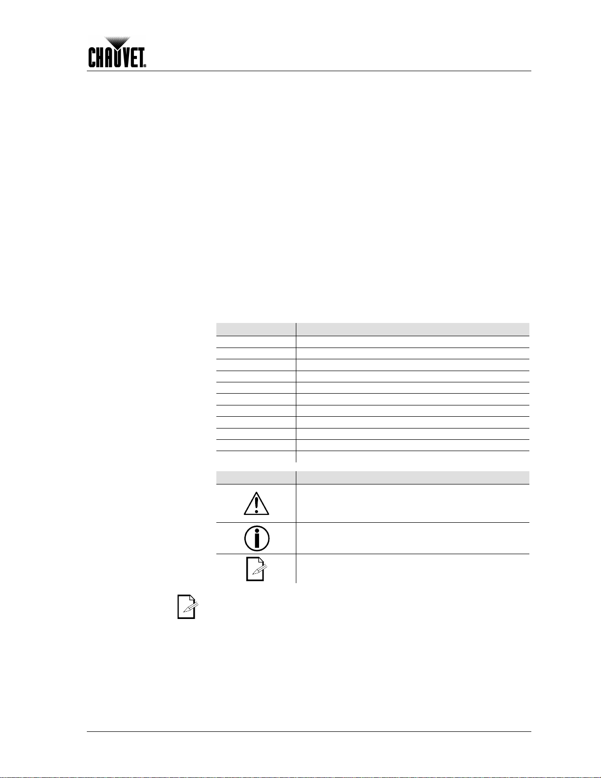
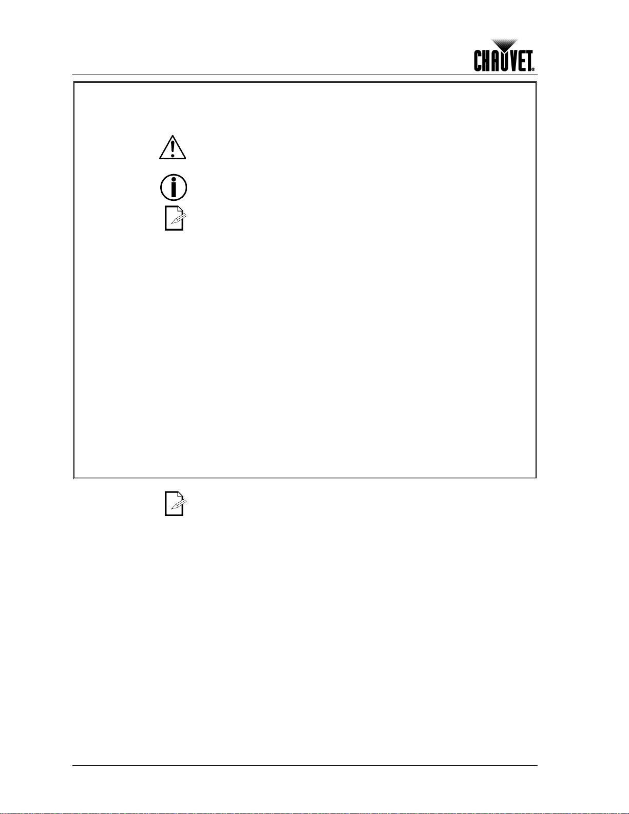
Icon Meaning
The term “ DMX” used through out this docum ent refers t o the USITT DMX512-A
transmission protocol.
COLORado™ 1-Tr i IP User Manual Rev. 01c -1-
Icon Meaning
information. Failure to comply with this information may render
the fixture partially or completely inoperative , damage third-party
This icon indicates important installation or configuration
information. Failure to comply with this information may pr ev en t
the fixture from functioning correctly.
This icon indicates useful, although n on-c ritical inf orm at i on .
Page 6
Before You Begi n
carefully because they include important safety
Safety Notes
Personal Safety
Mounting and Rigging
Power and Wiring
Please read the following notes
inform at i on ab ou t th e inst allation, usage, and maintenance of this product.
It is important to read all these notes before starting to work with this product.
There are no user serviceable parts inside this product. Any reference to
servicing it you may find from now on in this User Manual will only apply to
properly CHAUVET® certif ied technicians. Do not open the ho using or attempt
any repairs unless you are one of them.
Please refer to all applicable local codes and regulations for the proper
installation of this prod uct .
Keep this m anu al for future con sult ation. If yo u s el l this product to anot her user,
make sure that they also receive this manual.
• Avoid direct eye exposure to the light source while th e fixture is on.
• Always disconnect this product from its power source before servicing.
• Always connect this product to a ground ed circuit to avoi d th e ris k of el ectrocution.
• Do not touc h this product’s housing when operatin g b ec ause it may be ver y hot.
• This product is for in d oor an d out door use (IP66). Do not s u bm erge it.
• Make sure there are no flammable materials close to this product while operating.
• When hanging this product, al ways s ec ure it to a fasteni ng devi ce using a safety
cable (included).
• Always m ak e sure that you are connecting this product to the proper voltage, as
per the spec ifications in th is man u al or on th e product’s stic k er .
• Never connect this prod uc t to a dimmer pack or rheostat.
• Make sure the product’s housing or power cable are not cracked, crimped, or
damaged.
• Never disconnect this product by pulling or tugging on the power cable.
Operation
Expected LED
Lifespan
• Do not operate this fixture if you see damage on the housing, lenses or cables;
have the d am ag ed p ar ts r epl ac ed by an aut h or ized technician at once.
• The maximum ambient temperature (Ta) is 104° F (40° C). Do not operate this
product at a higher temperatur e.
• In case of a s erious op erating problem, stop using this product immediately!
In the un likely event that your CHAUVET® product may requir e servic e, plea se
contact CHAUVET® Technical Support.
LEDs gradu ally decline in bright ness over time, m ostly becaus e of heat. Pac kaged in
clusters, LEDs exhibit higher operating temperatures than in ideal, single LED
conditi ons. For this reas on, usi ng clustered LEDs at their fullest i ntensit y signif icantly
reduc es the LEDs’ lif espan. U nder n ormal con ditions , this lifes pan can b e of 40,000 t o
50,000 h ours. If ext ending this lifespan is vital, low er the oper ational temp erature by
improving the fixture’s ventil ation and reducing the external temperature. In addition,
limitin g th e overall pr oj ecti on intensit y m ay also help to extend the LEDs’ lifespan.
-2- COLORado™ 1-Tr i IP User Manual Rev. 01c
Page 7

2. Introduction
Introduction
Product
Description
Features
Additional Features
The CO LORado™ 1-T r i IP is an RG B w as h li gh t based on 14 tri-color LEDs. It consists
of a singl e p od wit h a d ou bl e bracket m ou nting yok e. T he AC power c om es d irectly int o
the fixture’s housing through a proprietary IP66 rated power input cord. The power
linking uses a proprietary IP66 rated power link cord. The DMX input and output signals
use proprietary IP66 DMX in and DMX out cords. The fixture comes with all the
neces sary a dap ter s t o connect to t he prop rieta ry IP66 cords as well a power and sign al
link cables. The COLORado™ 1-Tri IP uses a display-based control panel for
programming functions.
• 3, 4, 5, or 10-channel RGB LED wash light (with ID addressing)
• Operating modes:
3-channel: RGB control
3-channel: HSV (hue, saturation, an d val u e) control
4-channel: RGB, dimmer
5-channel: RGB, dimmer, strobe
10-channel: RGB, ID, dimmer, strobe, macro, auto/custom, dimmer speed,
• High power (3W) tri-color (RGB) LEDs
• RGB color mixing with or without DMX controller
• Automatic programs
• User configurable custom programs
• Recall aut o and custom programs via master/ s l ave or DMX
• Color temperature presets (3,200~10,000 K)
• Five distinct dimming curves
• 3-pin DMX input and output connectors
• Power linking: max 12 units @ 120 V
• LED display with password protection
• Gel fram e hol d er (4 m m m ax th ic kness)
• Double-brack et yoke that doubles as floor stand
• Color calibration
• Durable and weather resistant IP66 rated housing
• IP66 power and DMX connectors
auto speed
Options
COLORado™ 1-Tr i IP User Manual Rev. 01c -3-
• 16.4 ft (5 m) power extension cable (IP5POWER)
• 16.4 ft (5 m) signal extension cable (IP5SIG)
Page 8
Introduction
DMX Channel
Function
1 Master Dimmer
2
3 Green 4
Blue
5
6 Strobe
7 Auto Programs
8 Auto Speed Adjust
9 Dimmer Speed
10
ID Address
DMX Channel
Function
1 Red 2
Green
3
DMX Channel
Function 1
Master Dimmer
2 Red
3 Green
4 Blue
DMX Channel
Function
1 Master Dimmer
2
3 Green 4
Blue
5
DMX Channel
Function 1
Hue
2
3 Value
DMX Channel Summary
TOUR
Red
Color Mac ro
ARC1
AR1 + D
AR1 + S
HSV
Blue
Red
Strobe
Saturation
-4- COLORado™ 1-Tr i IP User Manual Rev. 01c
Page 9
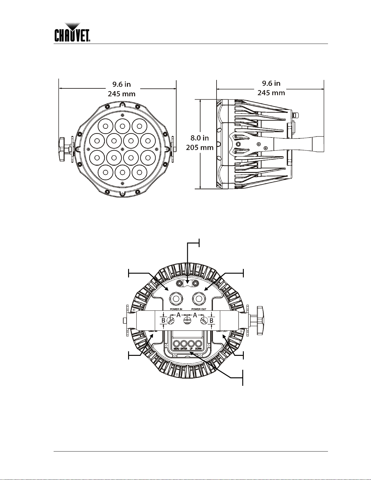
Product Overview
MX In
Power In
Safety cable passageway
A = 30 mm
B = 13 mm
D
Introduction
Power Out
DMX Out
Control Panel
(Plate removed)
COLORado™ 1-Tr i IP User Manual Rev. 01c -5-
Page 10

Setup
to a protected circuit with an
specifications
These power cords access the sealed body of the fixture
3. Setup
AC Power
The COLOR ado™ 1-Tri IP has an auto-rang ing power su pply that can work with an
input voltage range of 100~240 VAC, 50/60 Hz.
Make sure that you are connecting this product to the proper voltage, as per the
specifications in this guide, the product’s user manual, or on the product’s sticker.
Always connect the COLORado™ 1-Tri IP
appropriate elec tric al ground to avoid the risk of electr o cuti on o r fire.
To deter m in e th e power requ irements for the CO LO Rado™ 1-T ri IP see the label aff ixed
to the side of th e fi xture. A lter nat ivel y, you m ay ref er to the corresponding
chart in the Technical Informat io n chapter of this manual .
The list ed curren t rating i ndicates t he maxim um curr ent draw dur ing norm al operation.
For more information, you may download the “Sizing the Circuit Breakers” document
from the CHAUVET® Web site.
Never connect the COLORado™ 1-T ri I P to a rheostat (variable resistor) or dimmer
circuit, even if the rheostat or dimmer channel serves only as a 0 to 100% switch.
AC Plug
Each COLORado™ 1-Tri IP has IP66 rated cords for Power In and Power Out with
proprietary IP66 connectors.
through IP66 c able gl ands . T o allow c onn ecti on t o power out lets, t h e fixtur e c omes with
a power i np ut cord w it h a propri etary IP66 connec tor on one end an d an Edis on plug on
the other end (US mark et). In c ase you need t o replace the E dison plug on the power
input cord, follow the table below .
Power Linking
The CO LO Rado™ 1-T ri IP support s p ower li nkin g for up t o 12 other COLOR ado™ 1-Tri
IP f ixtures at 120 VAC. Th e fi xtur e als o c omes with an IP66 p ower li nkin g c ord to allow
direct connection between fixtures.
Fuse Replacement
The COLORado™ 1-Tri IP fixture has no external fuse that the user can change.
However , it does h ave an intern al fuse th at only an auth orized CH AUVET ® technici an
should change.
Connection
AC Live
AC Neutral
AC Ground
Wire (US) Wire (Europe) IP66 Pin Screw Color
Black Brown 1 Yellow or Brass
White Blue 2 Silver
Green/Yellow Green/Yellow 3 Green
-6- COLORado™ 1-Tr i IP User Manual Rev. 01c
Page 11

Setup
DMX Linking
DMX Modes
Master/Slave
Connectivity
You may link any COLORado™ 1-Tri IP fixtur e to a DMX c ontroller us ing a stand ard
DMX serial connection. If using other DMX compatible fixtures with a COLO Rado™ 1Tri IP fixture, it is possible to control them individually with a single DMX controller.
If you are n ot f amili ar with t h e DMX st and ard, or if you n eed inf or ma tion about the DM X
cables n eeded to link t he COLOR ado™ 1-Tri IP fixtur e to a DMX contr oller, you m ay
download the “DMX Primer” document from the CHAUVET® Web site.
The COLORado™ 1-Tri IP c omes with two adapt er cables, one from pr opriet ary
IP66 to 3-pin DM X In and the other from propr ietary IP66 to 3-pi n DMX Out. In
addition, it comes w ith a signal linking cab le with propriet ary IP66 conn ectors on
both ends.
The CO LOR ado™ 1-Tri IP uses the standard DM X d at a c on n ec ti on f or it s D M X m o d es ,
TOUR, ARC1, AR1+D, AR1+S, and HSV.
You will find information about these DMX modes in the Introduction chapter (brief
description), the Operation Instructions chapter (configuration details), and the DMX
Values section (individual channel values).
The Mast er/Slave mod e allows a COLOR ado™ 1-T ri IP fixtur e to c ontrol one or more
COLOR ado™ 1-T ri I P fixt ur es without a DMX controller. T h e control l i ng f ixture becomes
the “master” when running an auto or custom program as well as when in STATIC
mode. T he c ontr olled f ixtur es are th e “sl aves ” and you m ust s et th em t o “SLAV E” m ode
from their respective control panels. During the Master/Slave operation, the slave
fixtures will operate in unison with the master fixture.
The master and slave fixtures link to each other using the standard DMX serial
connect i on. I f you are not f amil i ar w it h t h e M as t er /S l av e connect ivit y, you may d ownload
the “DMX Primer” document from the CHAUVET® Web site.
DO NOT con ne ct a DMX controller to the fixtures o per ating in M ast er/Sl av e mo de .
Otherwise, the signals from the DMX controller may interfere with the signals from
the master unit.
The Operation chapter of this manual provides detailed instructio ns on how to
configure the Master and Slave units.
ID Addres sing
The CO LORado™ 1-T ri IP uses t he ID Addres sing featur e to increas e the numb er of
addressable f i xtures in th e same D M X u ni ver se wh en in the TOUR personality. Refer t o
the Operation chapter in this manual to learn in detail how to configure the
COLOR ado™ 1-Tri I P fixtur es when us ing I D A d dressing. If you are n ot famil iar wi th the
various connection m ethods wh en using ID Addr essing, you may download th e “DMX
Primer” document from the CHAUVET® Web site.
COLORado™ 1-Tr i IP User Manual Rev. 01c -7-
Page 12

Setup
Mounting
Orientation
Befor e m ounting this f ixture, read an d follow the s afety recomm endations indicated in
the Safety Notes section (pag e 2 of this manual).
Always m ount th is fixtur e in an y saf e position while m aking s ure that there is adequ ate
room around it for vent il ation, configuration, and maintenance.
Make sur e to mou nt this f ixture aw ay from any fl ammable m aterial as indicat ed in th e
Safety Notes section.
Rigging
The CO LORado™ 1-T ri IP cons ists of a sealed (IP66) housi ng with a dou ble brack et
mounti ng yoke. It h as two DMX s ignal c abl es (DMX In /D M X Out), an d t w o p ow er cabl es
(Power In/Power Out), al l of them fitted wit h pr opr i etary IP66 connectors.
CHAUVET® recommends f ollowing the general guidelines below when mounting the
COLORado™ 1-Tr i IP.
• When sel ect in g an install at i on location, consider ease of access to the fixture for
operation, progr am m in g adjustm ents , and routine maintenance.
• If hanging this fixture, make sure that the location where you are mounting the
fixture can support its weight. Please see the Technical Specifications section of this
manual for the weight requirement of this fixture.
Procedure
The COLO Rado™ 1 -Tri IP includes a saf ety cabl e and a mountin g yoke to which you
can attac h on e or two r igg ing c lamps . You m ust s uppl y your own “ C” or “O” c lamps and
make sur e that th ey are c apable of suppor ting the weight of t his fi xture. Alt hough it is
possib le to us e a sin gle cl amp per f ixtur e, CHAU VET ® recom mend s using two clamps
per fixture. Secure the fixture with the safety cable after mounting it to the truss.
C clamp
(not included).
Product Mounting
Diagram
Floor Mounting
Secure the safety cable using
the passageway on the b ack
of the fixture.
Overhead Mounting
-8- COLORado™ 1-Tr i IP User Manual Rev. 01c
Page 13

4. Operation
Exits fr om th e current menu or
function
Enables the currently displayed
numeric val u e wh en in a function
numeric val u e wh en in a function
channel TOUR personality. In
cues that need to trigger on
Control Panel
Description
Button Function
<MENU>
Operation
Control Options
Programming
DMX Personality
<ENTER>
<UP>
<DOWN>
You can s et the COLOR ado™ 1-Tri IP s tart address in the 001~ 512 DMX r ange. This
allows for the control of up to 51 fixtures in the 10additi on, th e ID addr ess s ystem allows you to assign up t o 66 fi xtures within t he s ame
DMX addr ess, thus multi plying the numb er of fixtures you c an control withi n a single
univers e. You c an access the fi xture’s ID address syst em from c hann el 10 when in t he
TOUR personality.
When programming live performances as well as
demand or on a tim e line, pro gram no more t han 10 fixtur es on ID addr essin g per
DMX channel. This is to remain within a one-second execution time.
Carry out all th e pr ogr ammin g pr oced ur es ind ic ated bel ow f rom th e cont rol p anel . R ef er
to the Menu Map on page 14 to learn how th e m enu op t i ons relate to each ot h er.
To go to an option, press <MENU> r ep e atedly until the option sh ow s on the displa y.
To sel ec t an option val ue, press <UP> or <DOWN> until you s ee the desir ed value and
press <ENTER> to accept it.
To exit to the previous m en u lev el, press <MENU>.
This setting allows the user to choose a particular DMX personality.
1) Go to PERS.
2) Select the desired personality (TOUR, ARC1, AR1 + D, AR1 + S, or HSV).
3) Make sure that the starting addresses on the various fixtures do not overlap due to
the new personality setting. See the DMX Values section.
menu or sets the currently
selected value in to the current
function
Navigates upwards through the
menu list and inc reases th e
Navigates downw ards t hr ough
the menu lis t an d decreas es th e
COLORado™ 1-Tr i IP User Manual Rev. 01c -9-
DMX Control
Without ID
Addressing
In this mode, each unit will respond to a unique starting address from the DMX
controller. All units with the same starting address will respond in unison.
1) Select the TOUR per so nality as shown in DMX Personality.
2) Set th e running mod e:
a) Go to RUN.
b) Select DMX.
3) Set th e st ar ti ng ad dress:
a) Go to DMX.
b) Select the starting address (001~512).
4) D eacti v at e ID A d dressing on eac h fi xture:
a) Go to SET > ID.
b) Select OFF.
Make sure to deactivate ID Addressing in each fixture when using the TOUR
personality. Ot herwise, uninten ded results may occur if ch annel 10 i s not set to
“0”.
Continues on the ne xt pag e
Page 14

Operation
fixtures (the slaves) to
DMX Control With ID
Addressing
Static Color
Auto Programs
Continued from previous page
In this m ode, the f ixtures with th e same D MX star ting ad dress w ill resp ond to th e DMX
controller based on the fixture’s individual ID address s etting. If the user selects ID
address “0”, all the fixtures with the same DMX address will respond in unison.
Otherwise, each fixture will follow the control for its particular ID address.
1) Repeat steps 1, 2, and 3 from DMX Control Without ID Addressing.
2) Act i vat e ID Ad dressing in eac h f i xture:
a) Go to SET > ID.
b) Select ON.
3) S elec t an ID add ress for each fixture:
a) Go to ID.
b) Select an ID (01~66)
The Static Color mode allows for permanent RGB color mixing without a DMX controller.
1) Go to STAT.
2) Select the desired color (Red, Green, or Blue).
3) Select t he d esired color v a lu e ( 0~255).
4) Repeat for the other colors.
5) Select Strob.
6) Select the desired frequency (0~20).
Auto programs allow for dynamic RGB color mixing without a DMX controller.
1) Go to AUTO.
2) Select the desired auto pr ogr am (AT. 01~10 or PR. 01~10).
You cannot edit auto programs AT. 01 ~10. However you ca n edit PR. 01~10 (see
Edit Customs).
Edit Customs
This setting allows for the programming of up to 30 scenes for each of the 10
customizable programs, including colors and effects.
1) Go to EDIT.
2) Select the desired auto pr ogr am (PR. 01~10).
3) Select the desired scene (SC. 01~30).
4) Select the desired color or effect (Red, Green, Blue, Strobe, Time, or Fade).
5) Select the desired value for the color or effect (000~255 for colors and timers, or
00~20 for Strobe).
6) Repeat for the other colors or effects.
7) Repeat for the other scenes.
Master/Slave
The Master/ Slav e mode allows a gr oup of COLOR ado™ 1 -T ri IP
execute simultaneously the same program, whether auto or custom, that another
COLORado™ 1-Tr i IP fixture ( th e m aster) is executing, wit h out a DMX controller.
1) Set th e M ast er Unit:
a) Set the running mode to DMX as explained in “DMX Control Without ID
Addressing”.
b) Select a n au t o pr ogr am as explai n ed in “ Auto Programs”.
2) Set the slave units:
a) Go to RUN.
b) Select SLAV.
• The fixture that runs an auto program automatically becomes the Master.
• Do not connect a DMX controller to the master or slave fixtures.
Continues on the ne xt pag e
-10- COLORado™ 1-Tr i IP User Manual Rev. 01c
Page 15

Operation
displays the white color
OFF
follows the position
activate or disable the control panel lock, which keeps
Color Adjustment
Dimmer Curves
Control Panel Lock
Continued from previous page
The COLOR setting determines how the COLOR ad o™ 1-T ri IP
when the Red, Green, and Blue faders are all at the “255” value.
1) Go to SET > Color.
2) Select OFF, RGBW, or UC.
Setting Description
When R, G, and B are “255,” the output will be at its maximum.
RGBW When R, G, and B are “255,” CAL2 will determine the output.
UC
When R, G, and B are “255,” the output will match that of fixtures from
previous g en er at ions.
This s etti ng determines h ow th e output of the C O LO R ado™ 1-T ri IP
of the Dimmer fader, as well as the Red, Green, and Blue faders.
1) Go to SET > Dim.
2) Select a dimmer curve (Off, Dim1, Dim2, Dim3, or Dim4).
Setting Description
OFF The output is proportional to the faders’ position (linear)
Dim1 The output is not proportional (fastest)
Dim2 The output is not proportional (fast)
Dim3 The output is not proportional (slow)
Dim4 The output is not proportional (slowest)
This s ettin g allows th e user to
non-authorized personnel from changing the fixture’s settings.
1) Go to KEY.
2) Select On/ Off.
When the contr ol pan el lock is activ e, the fixt ure will pr ompt t he us er to enter t he
password after 30 seconds of control panel inactivity or after turning on the
fixture.
After being prompted to enter the password:
1) Press <UP>, <DOWN>, <UP>, <DOWN>, and <ENTER>.
Program Upload
This opti on allow s the us er to cop y the c ustom pr ogr ams of on e COLOR ado™ 1-Tri IP
fixture onto other CO LO Rado™ 1-Tri IP fi xtures by using the M aster/Sl ave m et hod.
1) Configure and connect the fixtures in a Master/Slave arrangement, where the
master un it has the cust om programs y ou w an t to tr ans fer ont o the sl av e uni ts .
2) At the master unit, go to SET > UPLD.
3) W hen pr om pt ed, enter th e mas t er access pass wor d as sh ow n in Control Panel
Lock.
4) Wai t for the upload process to finish be fore disconnecting the fixtures.
During and aft er the uplo ad, the mast er and slave unit s will vis uall y indic ate th e status of
the process, as follows:
Color Meaning
Yellow The upload process is running
Red The upload failed due to an error
Green The upload finished successfully
COLORado™ 1-Tr i IP User Manual Rev. 01c -11-
Continues on the ne xt pag e
Page 16

Operation
Reset
This setting allows the user to reset the COLORado™ 1-Tri IP fixture to its def ault
values, including the custom programs.
1) Go to SET> REST.
2) W hen pr om pt ed, enter th e mas t er access pass wor d as sh ow n in Control Panel
3) Wait for the reset process to finish.
Whites Setting
This s etting all ows the us er to ed it the tem peratur e of the 1 1 white colors us ed in th e
Macros channel. The 11 pre-set whites are conf igurable.
1) Go to CAL1.
2) Select a white color (WT. 1~11).
3) Select a color (Red, Green, or Blue).
4) Select a color value (0~255).
5) Repeat for the other colors (Red, Green, or Blue).
6) Repeat for the other white colors (WT. 1~11).
White Calibration
This setting allows the user to select the white color shown by the COLOR ado™ 1-Tri IP
when the c ol or s ettin g is RGBW and th e DM X contr ol ler’s R ed, Gr een, and B lue faders
are set to “255”.
1) Go to CAL2 > RGBW.
2) Select a color (Red, Green, or Blue).
3) Select a color value (0~255).
4) Repeat for the other colors (Red, Green, or Blue).
Continued from previous page
Lock.
-12- COLORado™ 1-Tr i IP User Manual Rev. 01c
Page 17

TOUR Notes
Ma ster Dimmer
Red, Green, & Blue
Color Selection
Color Macros
Strobe
Auto
Dimmer Speed
Dim1
Dim4
ID Address
Operation
These notes intent to clarify the way the TOUR DMX personality works.
• Channel 1 controls the intensity of the curr en t l y pr ojected col or .
• When the slider is at the hi ghest po si tion (255) the in tensity of the output is at its
maximum.
• Channels 2, 3, and 4 control the intensity ratio of each of the Red, Green, and Blue
LEDs.
• When the slider is at the hi ghest po si tion (255), the intensity of eac h c olor is at its
maximum.
• You can combine channels 2, 3, and 4 to create over 16 million colors.
• Channel 5 selects the required Color Macro.
• Channel 5 has prior i t y over channels 2, 3, and 4.
• Channel 1 controls the intensity of the Color Macro.
• Channel 6 controls the strobe frequency (not the intensity) of channels 2~5.
• Channel 6 strobes channels 2, 3, and 4 when not running macr os , allowing th e
individual faders (R, G, and B) as well as channel 1 (D) to control the output
intensity.
• Channel strobes channel 6 when run ning macros, allowing channel 6 to select the
macro and channel 1 to control the output intensity.
• Channel 7 selects the preset auto programs AT. 01~10 or the custom programs
CUS. 01~10.
• When activating the custom programs CUS. 01~10, it is possible to control the Step
Time and F ad e Ti m e usi ng ch ann els 2 and 3 respectively .
• Channel 7 has prior i t y over channels 2, 3, 4, 5, and 6.
• Channel 9 is for s elec ti ng t h e di m m er m od e an d sp eed . When Dimmer is set to Off,
• Channel 10 selects the target ID address.
Selection
• Each ind ep end ent DMX address may hav e up t o 66 ind ep endent ID ad dresses.
• An ID addres s of 0 will act ivate all ID ad dress loc ati ons .
the Red, Green, Blue, and Dimmer outp ut s ar e linear with the faders. Oth er wise,
is the fastest dimmer curve, while
is the slowest.
COLORado™ 1-Tr i IP User Manual Rev. 01c -13-
Page 18

Operation
Menu Map
-14- COLORado™ 1-Tr i IP User Manual Rev. 01c
Page 19

DMX Values
1
Master Di mmer
000 ó 255
0~100%
Red
0~100% (or)
Step Time
When playing a custom program
Green
0~100% (or)
Fade Time
4
Blue
000 ó 010
251 ó 255
No function
White 11: 10,000 K
000 ó 010
011 ó 255
No function
0~20 Hz
000 ó 020
221 ó 255
No function
No function
8
Auto Speed
000 ó 255
0~100% (O nl y when playing an automatic program)
Operation
TOUR
Channel Function Value Percent/Setting
2
3
5 Color Macro
6 Strobe
000 ó 255
000 ó 255
000 ó 255 0~100%
011 ó 030
031 ó 050
051 ó 070
071 ó 090
091 ó 110
111 ó 130
131 ó 150
151 ó 170
171 ó 200
201 ó 205
206 ó 210
211 ó 215
216 ó 220
221 ó 225
226 ó 230
231 ó 235
236 ó 240
241 ó 245
246 ó 250
When playi n g a custom program
R: 100% G: Up B: 0%
R: Down G: 100% B: 0%
R: 0% G: 100% B: Up
R: 0% G: Down B: 100%
R: Up G: 0% B: 100%
R: 100% G: 0% B: Down
R: 100% G: Up B: Up
R: Down G: Down B: 100%
R: 100% G: 100% B: 100% W: 100%
White 1: 3,200 K
White 2: 3,400 K
White 3: 4,200 K
White 4: 4,900 K
White 5: 5,600 K
White 6: 5,900 K
White 7: 6,500 K
White 8: 7,200 K
White 9: 8,000 K
White 10: 8,500 K
7 Auto
9 Dimmer Sp e ed
Continues on the ne xt pag e
021 ó 030
031 ó 040
041 ó 050
051 ó 060
061 ó 070
071 ó 080
081 ó 090
091 ó 100
101 ó 110
111 ó 120
121 ó 130
131 ó 140
141 ó 150
151 ó 160
161 ó 170
171 ó 180
181 ó 190
191 ó 200
201 ó 210
211 ó 220
000 ó 009
010 ó 029
030 ó 069
070 ó 129
130 ó 189
190 ó 255
Auto 1
Auto 2
Auto 3
Auto 4
Auto 5
Auto 6
Auto 7
Auto 8
Auto 9
Auto 10
Custom 1
Custom 2
Custom 3
Custom 4
Custom 5
Custom 6
Custom 7
Custom 8
Custom 9
Custom 10
Use dimmer speed from control panel
Linear dimmer
Non-lin ear dimmer 1 (f ast est )
Non-lin ear dimmer 2
Non-lin ear dimmer 3
Non-lin ear dimmer 4 (slow es t)
COLORado™ 1-Tr i IP User Manual Rev. 01c -15-
Page 20

Operation
000 ó 009
All IDs
212
ID 23
235
ID 46
1
Red
000 ó 255
0~100%
2
Green
000 ó 255
0~100%
3
Blue
000 ó 255
0~100%
1
Master Di mmer
000 ó 255
0~100%
2
Red
000 ó 255
0~100%
3
Green
000 ó 255
0~100%
4
Blue
000 ó 255
0~100%
1
Master Di mmer
000 ó 255
0~100%
2
Red
000 ó 255
0~100%
3
Green
000 ó 255
0~100%
4
Blue
000 ó 255
0~100%
000 ó 010
011 ó 255
No function
0~20 Hz
TOUR (Cont.)
ARC1
Continued from previous page
Channel Function Value Setting Value Setting Value Setting
010 ó 019
020 ó 029
030 ó 039
040 ó 049
050 ó 059
060 ó 069
070 ó 079
080 ó 089
090 ó 099
10 ID Addr ess
Channel Function Value Percent/Setting
100 ó 109
110 ó 119
120 ó 129
130 ó 139
140 ó 149
150 ó 159
160 ó 169
170 ó 179
180 ó 189
190 ó 199
200 ó 209
210
211
ID 1
ID 2
ID 3
ID 4
ID 5
ID 6
ID 7
ID 8
ID 9
ID 10
ID 11
ID 12
ID 13
ID 14
ID 15
ID 16
ID 17
ID 18
ID 19
ID 20
ID 21
ID 22
213
214
215
216
217
218
219
220
221
222
223
224
225
226
227
228
229
230
231
232
233
234
ID 24
ID 25
ID 26
ID 27
ID 28
ID 29
ID 30
ID 31
ID 32
ID 33
ID 34
ID 35
ID 36
ID 37
ID 38
ID 39
ID 40
ID 41
ID 42
ID 43
ID 44
ID 45
236
237
238
239
240
241
242
243
244
245
246
247
248
249
250
251
252
253
254
255
ID 47
ID 48
ID 49
ID 50
ID 51
ID 52
ID 53
ID 54
ID 55
ID 56
ID 57
ID 58
ID 59
ID 60
ID 61
ID 62
ID 63
ID 64
ID 65
ID 66
ARC1 + D
AR1 + S
-16- COLORado™ 1-Tr i IP User Manual Rev. 01c
Channel Function Value Percent/Setting
Channel Function Value Percent/Setting
5 Strobe
Continues on the ne xt pag e
Page 21

Operation
1
Hue
000 ó 255
0~100%
2
Saturation
000 ó 255
0~100%
3
Value
000 ó 255
0~100%
HSV
Channel Function Value Percent/Setting
• “Hue” refers to the visible lig ht, su ch as red, yel lo w, and cy an, e tc.
• “Saturation” indicates th e dominance of hue in t he color; when saturati on is at 1 00%,
the color is at its purest.
• “Value” is the color’s brightness; when value is at 100%, the color is at its brightest.
Continued from previous page
COLORado™ 1-Tr i IP User Manual Rev. 01c -17-
Page 22

Technical Information
5. Technical Information
General
Maintenance
To maintai n optimum per formanc e and minimi ze wear, the us er should cl ean the light
fixtures fr equentl y. Us age and envir onm ent are c ontr ibutin g f actors in det erminin g th e
cleani ng f requenc y. A s a rule, the user sh oul d c lean the fixtures at l e ast twice a m onth.
Dust buil d up red uces ligh t output perform ance and c an cause overheati ng. This can
lead to reduced light s ource life and inc reased m ec h anical wear .
CHAUVET® rec ommends cleaning t he fixtur e’s exter nal optic s with a s oft cloth usi ng
normal glass cleaning fluid.
To clean a fixture, follow the recommendations below:
• Unplug the fixture from power.
• Wait until the fixture is cold.
• Use a vacuu m (or dr y c ompress ed air) an d a s oft brus h to remove du s t coll ec t ed
on the external vents and r eac h abl e internal c omp on ents.
• Clean all external optics and gl ass surfaces with a mild solut i on of gl a s s clean er or
isopropyl alcohol, and a soft, lint free cotton cloth or a lens cleaning tissue.
• Apply the solution directly to the cloth or tissue and drag any dirt and grime to the
outsid e of the lens.
• Gentl y polish the exter n al gl ass s ur f ac es unt i l th ey are free of haz e a nd li nt .
• When clean i ng unit s with a movabl e mirror, you s h oul d k eep the contact wit h the
mirror surface to a minimum to avoid scratching or damaging it.
Always dry the external optics and glass surfaces carefully after cleaning them.
If the fixture has one or more cooling fans, refrain from spinning them using
compressed air.
-18- COLORado™ 1-Tr i IP User Manual Rev. 01c
Page 23

Troubl es h oo ti n g Guide
Symptom Cause(s) Action(s)
Gener al low lig ht in tensity
A sing le tri color LED
does not illuminate
A group of tri-color LEDs
does not illuminate
None of the LEDs are
illuminating
Breaker /F use keeps
blowing
Fixture d oes not power up
Fixture does not respond
to DMX
DMX signal problems
• Dirty lens assembly • Clean the fixture regularly
• Misaligned lens assembly • Inst all l ens assembly pr op erly
• Faulty LE D • Replace the LED board
• Faulty LE D board • Replace the LED board
• Faulty LE D • Replace the LED board
• Faulty LE D board • Replace the LED board
• Faulty LE D driver • Replace the LED driver board
• Faulty LE D PCB • Replace the LED board
• Faulty LED Driver PCB • Replace the LED driver board
• Faulty main PCB • Replace the Display / Main board
• Excessive circuit load • Check total load placed on the electrical circuit
• Sho rt circuit along the power wires • Check for a short in the electrical wiring
• No power • Check for power on pow er ou tl et
• Loose or damaged power cord • Check power cord
• Blown internal fuse • Replace internal fuse
• Faulty internal power supply • Replace internal power supply
• Wrong DMX addressing • Check Control Panel and unit addressing
• Damaged DMX cables • Check DMX cables
• Wrong pol ar it y on the controller • Check polarity switch settings on the controller
• Loose DMX cables • Check cable connec tions
• Faulty DMX interface • Replace Main PCB
• Faulty Main PCB • Replace Main PCB
• Non DMX cables • Use only DMX compatible cables
• Bouncing signals • Install ter mi n at or as su gg es t ed
• Long cable / low level signal • Install an optically coupled DMX splitter right
• Too many fixtures • Install an optically coupled DMX splitter after
• Interference from AC wires • Keep DMX cables separated from power cables
If you still experience technical problems after trying the above solutions, contact
CHAUVET® Technical Support.
after fixture with strong signal
unit #32
or black lights
Technical Information
COLORado™ 1-Tr i IP User Manual Rev. 01c -19-
Page 24

Technical Information
Item
Description
Item
Description
1
Front cover
11
Display clear plate
2
Rubber seal (*)
12
Button seal
3
Clear glass
13
Casing
4
14
5
LED board
15
Power cord gland
6
Heat sink
16
Display protecti on plate
7
17
8
Driver b oard
18
DMX cable gland
9
Power conn ect i on board
19
Main brac k et
10
Display b oard
20
Secondary bracket
Exploded View
-20- COLORado™ 1-Tr i IP User Manual Rev. 01c
Lens complete set
Power supply
The rubber seal can be a separate ring or it may come mounted around the
(*):
glass cover
Stainless steel knob
Display plate seal
Page 25

Technical Information
Photometrics
COLORado™ 1-Tr i IP User Manual Rev. 01c -21-
Page 26

Technical Information
with its original
to have
Returns
Procedure
Claims
Contact Us
The us er must s end the mer chandis e prepaid, in the orig inal box, and
packi ng a nd ac cess ori es. CHA UVE T® will not issue call tags.
Call CHAUVET® and request a Return Merchandise Authorization Number (RMA #)
before s hipping th e fixture. B e prepared t o provide t he model nu mber, seri al number,
and a brief description of the cause for the return.
The user must clearly label the package with a Return Merchandise Authorization
Number (RMA #). CHAUVET® will refuse any product returned without an RMA #.
DO NOT write t he R MA # directly on the box. In ste ad, wr ite it on a pro per ly a ffix ed
label.
Once you receive the RMA #, pleas e include the following information on a piece of
paper inside the box:
• Your name
• Your addr es s
• Your phone number
• The RMA #
• A brief description of the problem
Be sure to p ack th e fixture prop erly. Any shipping damag e resul ting from inad equate
packaging will b e the c us t om er ’s respons ib il ity. As a s uggesti on, proper UPS p ac ki ng or
double-boxing is always a safe method to use.
CHAUVET® reserves the right to use its own discretion to repair or replace
returned product(s).
The carrier is r esp onsibl e for any damag e incurred du r i ng s hi pping t o t his pr oduct or any
part that shipped with it. Therefore, if the received merchandise appears
damages caus ed durin g s hi pp ing, the cus tomer mus t s ubmit the d am age report an d any
related clai ms wit h the c arrier, n ot CHAUV ET®. Th e custom er mu st submi t the r eport
upon rec eption of the d amaged merc handis e. Failure to do s o in a timely mann er may
invalidate the customer’s claim with the carrier.
For other iss ues s uch as mis sing c om pon ents or p arts , dam age n ot relat ed t o shi ppin g,
or conc eal ed d amag e, t he c ust omer must make clai ms t o CH AUVE T ® within s even (7)
days of rec ei vi ng t h e m erc handis e.
World Headquarters
General Inform ation
CHAUVET®
5200 NW 108th Avenue
Sunrise, FL 33351
Voice: (954) 929-1115
Fax: (954) 929-5560
Toll free: (800) 762-1084
Technical Supp or t
Voice: (954) 929-1115 (Press 4)
Fax: (954) 756-8015
World Wide Web
www.chauvetlighting.com
-22- COLORado™ 1-Tr i IP User Manual Rev. 01c
Page 27

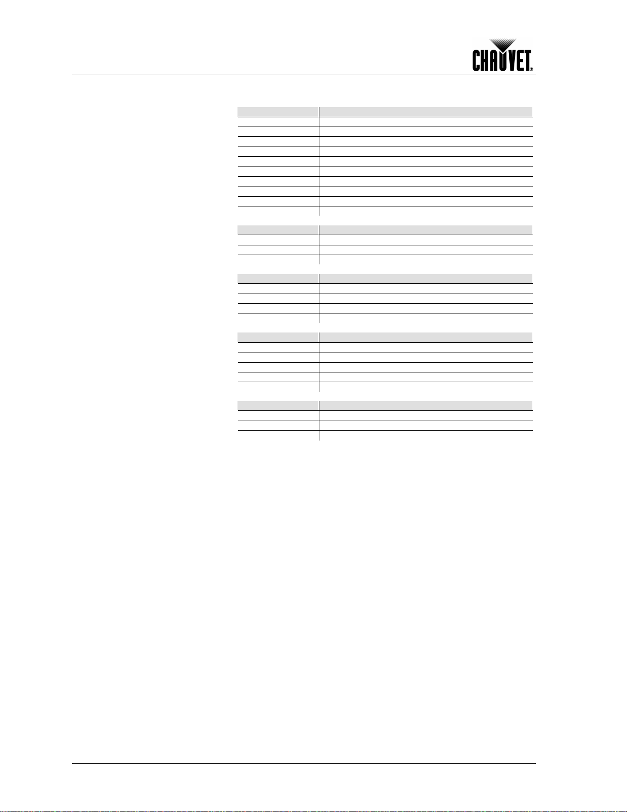
Dimensions and Weight
Length
Width
Height
Weight
9.6 in (245 mm)
8.0 in (205 mm)
9.6 in (245 mm)
10.6 lbs (4.8 kg)
Note: Dimensions in inches rounded to the nearest decimal digit.
Power
Power Supply Type
Range
Voltage Selection
Switching (internal)
100~240 V, 50/60 Hz
Auto-ranging
Parameter
120 V, 60 Hz
230 V, 50 Hz
Consumption
88 W (0.7 A)
88 W (0.4 A)
Inrush current
0.4 A
0.4 A
Power Linking
12 units
24 units
Power I / O
Input
Output
Connectors
In-line proprietary IP66
In-line proprietary IP66
Cord plu g (US)
Proprietary IP66 to Edison
Proprietary IP66
Light Source
Type
Power
Lifespan
LED
3 W
50,000 h ours
Color
Quantity
Current
Tri-co lor (RGB)
14
1,050 mA per die
Photo Opt ic
Parameter
Standard 16º Optics
Beam angl e
17º
Field angle
32º
Thermal
Maximum External Temp.
Cooling Syste m
104° F (40° C)
Convection
DMX
I/O Connectors
Connector Type
Channel Range
3-pin XLR (IP66 adapter)
In-line
3, 4, 5, and 10
Ordering
COLORado™ 1-Tri IP
Power ext en si o n cable
Signal extensio n ca ble
COLORADO1TRIIP
IP5POWER
IP5SIG
Technical Specifications
Technical Information
Illuminance @ 5 m 306 lx
COLORado™ 1-Tr i IP User Manual Rev. 01c -23-
Page 28

CHAUVET®
5200 NW 108th Avenue
Sunrise, FL 33351 (USA)
(800) 762-1084 – ( 95 4) 92 9-1115
FAX (954) 929-5560
www.chauvetlighting.com
COLORado™ 1-Tr i IP User Manual Rev. 01c
December 2010
 Loading...