

Page 1

User Manual
Page 2

TABLE OF CONTENTS
1. Before You Begin ...........................................................................................................3
What Is Included ......................................................................................................................... 3
Unpacking Instruc tions ................................................................................................................ 3
Claims ................................................................................................................................................. 3
Text Conventions ........................................................................................................................ 3
Symbols ...................................................................................................................................... 3
Disclaimer ................................................................................................................................... 3
Product at a Glance ..................................................................................................................... 4
Safety Notes ............................................................................................................................... 4
2. Introduction ....................................................................................................................5
Overview ..................................................................................................................................... 5
Dimensions ................................................................................................................................. 6
3. Setup ...............................................................................................................................7
AC Power .................................................................................................................................... 7
Fus e Repl acement ............................................................................................................................... 7
Mounting ..................................................................................................................................... 8
Orientation ........................................................................................................................................... 8
Rigging ................................................................................................................................................ 8
4. Operation ........................................................................................................................9
Control Panel Operation .............................................................................................................. 9
Menu Map ................................................................................................................................... 9
Configuration ( DM X) .................................................................................................................... 9
Starting Address .................................................................................................................................. 9
DMX Channel Mode, Assignm ents, and Values ......................................................................... 10
6-Channel .......................................................................................................................................... 10
Configuration ( S tandalone) ........................................................................................................ 11
Sound-Active Mode ............................................................................................................................ 11
Automatic Mode ................................................................................................................................. 11
Master/Slave Mode ............................................................................................................................ 12
5. Technica l Information ..................................................................................................13
Product Maintenanc e ................................................................................................................ 13
6. Techni cal Sp eci f ications ..............................................................................................14
Returns ..................................................................................................................................... 15
Contact Us ................................................................................................................................ 15
Page 2 of 15 Minisphere™ 3.1 User Manual (Rev. 1)
Page 3
What Is
Included
Unpacking
Instructions
and check the container to make sure all the
included accessories) appear damaged from
missing components or parts, damage not related to shipping,
Text
1~512
A range of values
50/60
A set of values of which only one can be chosen
Settings
A menu option not to be modified
Menu > Settings
A seq uence of menu opti ons to b e followed
<ENTER>
A key t o be pr essed on th e product’s control panel
ON
A value t o be entered or selected
Symbols
Critical installation, configuration, or operation informa tion. Not
damage to the product, or cause harm to the operator.
Disclaimer
are subject to change
ity for any errors or
1. BEFORE YOU BEGIN
Claims
Conventions
• Minisphere™ 3.1
• Power Cord
Carefully unpack the product immediately
parts are in the package and ar e in good condition.
If the box or the contents (the product and
shipping, or show signs of mishandling, notify the carrier immediately, not CHAUVET®.
Failure to report damage to the carrier immediately may invalidate your claim. In
addition, keep the box and contents for inspection.
For ot her iss ues, such as
or concealed damage, file a claim with CHAUVET® within 7 days of delivery.
Convention Meaning
Symbol Meaning
• Warranty Card
• Quick Reference G uide
The information and specifications contained in this User Manual
without notice. CHAUVET® assumes no responsibility or liabil
omissions, and reserves the right to revise or recreate this manual at any time.
Download the latest version from www.chauvetlighting.com.
© Copyright 2012 CHAUVET®. All rights reserved. Electronically published by
CHAUVET® in th e Un it ed States of Am er ica.
Author Date
S. Dia z 12/13/12
following these instructions may make the product not work, cause
Important installation or configuration information. The product
may not function correctly if this i nformation i s not us ed.
Useful information.
Minisphere™ User Manual (Rev. 1) Page 3 of 15
Page 4
Product at a
Replaceable Fuse
Circuit breaker
Safety Notes
• Always m ake s ure that the voltag e of the outlet to which you are connect ing the
Glance
Use on Dimmer
Outdoor Use
Sound Activated
DMX
Master/Slave
These notes include important information about the mounting, usage, and maintenance
of this product; read before using the product.
• Always connect the product to a grounded circuit to avoid the risk of electrocution.
• Always disconnect the product from the power source before cleaning or replacing
the fuse.
• Avo id di rect eye exp osure to the l ight sour ce whi le th e product is on.
• Make sure the power cord is not crimped or damaged.
• Never disconnect the product from power b y pull ing or tugging on th e cord.
• If mounting the product overhead, always secure t o a fas tening dev ice using a
safety cable.
• Make sure th ere are no flammable materials close t o the product when operating.
• Do not touch the product’s housing when operating because it may be very hot.
product is within the range stated on the decal or rear panel of the product.
• The product is for indoor us e only! To p reven t risk of fir e or shoc k, do not exp ose
the product to rain or moisture.
• Always install the product in a location with adequate ventilation, at least 20 in (50
cm) from adjacent surfaces.
• Be su re that no ventilation slots on the product’s housing are blocked.
• Nev er co nnect the product to a dimmer.
• Make sure to repl ace the fus e w ith a noth er of t he same typ e and r ating.
• Nev er ca r ry the product fr om the power cord or an y moving pa rt. Alwa ys use the
base or mounting brackets.
• The maximum ambient t emperature ( Ta) i s 104° F (40° C) . Do not oper ate the
product at higher temperatures.
• In the event of a serious oper ati ng problem, stop using the product immediately.
• Nev er tr y to repair the product. Repairs carried out by unskilled people can lead to
damage or malfunction. Contact th e near est a uthorized techni cal assistance center.
• This product is not intended for permanent installation.
Auto Programs
Auto-ranging Power Supply
User Serviceable
Duty Cycle
• Keep this User Manual for future use. If you sell the product to another user, be
sure to give this document t o the next o wner .
Page 4 of 15 Minisphere™ 3.1 User Manual (Rev. 1)
Page 5
2. INTRODUCTION
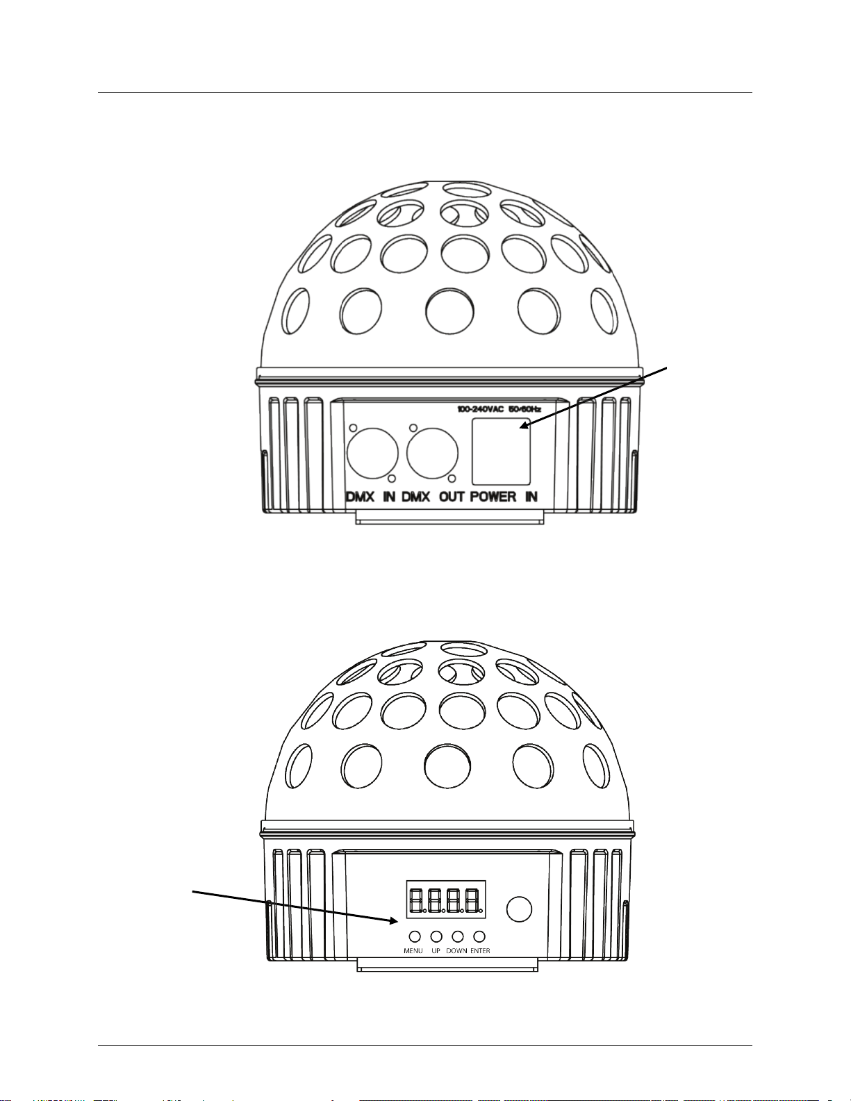
Overview
Fuse Holder
Menu Display
Front Panel View
Back Panel View
Minisphere™ User Manual (Rev. 1) Page 5 of 15
Page 6

Dimensions
7.2 in
182 mm
6.3 in
160 mm
Page 6 of 15 Minisphere™ 3.1 User Manual (Rev. 1)
Page 7

AC Power
ranging power supply and it can work with an input
(circuit breaker or fuse). Make
an appropriate electrical ground to avoid the risk of
a rheostat (variable resistor) or dimmer circuit, even
Fuse
Installed fuse
(held by plastic clip)
Spare fuse holder
(inside safety cap)
Safety cap
3. SETUP
The Mini sphere™ 3.1 has an autovoltage range of 100~240 VAC, 50/60 Hz.
To determine the product’s power requirements (circuit breaker, power outlet, and
wiring), us e the current value listed on the label affixed to the product’s back panel, or
refer to the product’s specifications chart. The listed current rating indicates the
product’s average current draw under normal condition s.
Always connect the product to a protected circuit
sure the product has
electrocution or fire.
Never connect the product to
if the rheostat or dimmer channel serves only as a 0~100% switch.
Replacement
Disconnect the product from power before replacing the fuse.
1. Disconnect the product from power.
2. Wedge t he tip of a flat-head scre w drive r into the slot of the fuse holder.
3. Pry the fuse holder out of the housing.
4. Remove the blown fuse from the holder.
5. Replace with a fuse of the exa ct same type and rating.
6. Insert the fus e holder ba ck in place and reconnect power.
A spare fuse is not included; however, the safety cap has room for a spare.
Minisphere™ User Manual (Rev. 1) Page 7 of 15
Page 8

Mounting
, read and follow the safety recommendations indicated in
may be mounted in any position; however, make sure adequate
Rigging
Mount the
Mounting Brackets
Before mounting the product
the Safety Notes.
Orientation
The Mini sphere™ 3.1
ventilation is provided around the product.
• Before deciding on a location, always make sure there is easy access to the product
for maintenance and programming.
• Make su re th at th e str uctur e or surface onto which you are mounting the product
can support the product’s weight (see the Technical Specifications).
• When mounting the product overhead, always use a safety cable.
product securely to a rigging p oint , such as an elevated plat form or a tr uss.
• When rigging the product onto a truss, you should use a mounting clamp of
appropriate weight capacity.
Mounting Diagram
Page 8 of 15 Minisphere™ 3.1 User Manual (Rev. 1)
Page 9

Control Panel
Operation
To access the control panel functions, use the four buttons located underneath the
<DOWN>
Menu Map
Mode
Programming Steps
Description
Configuration
Starting Address
choose a starting address that is too high, you could
DMX mode, which defines
download the DMX Primer from
4. OPERATION
(DMX)
display.
Button Function
<MENU> Selects an operation mode or to backs out of th e current menu opti on
<UP> Scrolls u p the list of options or selects a higher value
Scrolls down the list of options or selects a lower value
<ENTER> Activates a menu opt ion or a selected value
DMX Mode 512 d 1–d512 Selects th e D M X starti ng address
Auto Programs P-- P1–P9 Selects aut omatic program
Auto Program
Speed
Sound-Active SNd Starts sound-activated pro grams
Set the product in DMX mode t o control with a D M X cont rol ler.
1. Connect the product to a suitable po w er outlet .
2. Turn the product on.
3. Connect a DMX cable from the DMX output of the DMX controller to the DMX input
socket on the product.
S-- S 1–S100 Sets au t omatic-program speed
Wh en selec ting a s tart ing DMX addres s, alw ays co nsider the num ber of DMX cha nnels
the selected DMX mo de uses. If you
restrict t he ac cess t o som e of t he product’s channels.
The Minisphere™ 3.1 uses up to 6 DMX channels in its single
the highest configurable address to 507.
If unfamiliar with DMX or DIP switches,
www.chauvetlighting.com.
To select the starting address, do t he following:
1. Press <MENU> repeatedl y until 512 shows on the display.
2. Press <ENTER>.
3. Use <UP> or <DOWN> to select the starti ng address (d 1–d512).
4. Press <ENTER>.
Minisphere™ User Manual (Rev. 1) Page 9 of 15
Page 10

DMX Channel Mode, Assignments, and Values
1
Red
000 255
0–100%
2 Green
000 255
0–100% 3
Blue
000 255
0–100%
000 039
200 255
No function
counterclockwise rotation
000 009
010 255
No function
0–100% 6
Strobe
010 255
1~30 Hz
6-Channel
Channel Function Value Setting
4 Automatic Programs
5 Motor Rotation
040 079
080 119
120 159
160 199
3-Colo r switchi ng
7-Colo r switchi ng
3-Color fade
7-Colo r switchi ng, clockwise and
Page 10 of 15 Minisphere™ 3.1 User Manual (Rev. 1)
Page 11

Configuration
standalone mode may transmit DMX signals that could interfere with the DMX
Active
Automatic
(Standalone)
Set the product in one of the standalone modes to control without a DMX controller.
1. Connect the product to a suitable po w er outlet .
2. Turn the product on.
Never connect a product that is operating in a ny standalone mode (either Static,
Automatic, or Sound) to a DMX stri ng connected to a DMX controller. Products in
signals from the controller.
Sound-
Mode
To enable the Sound-Active mode, do the following:
1. Press <MENU repeatedly until SNd shows on the display.
2. Press <ENTER>.
The product will only respond to low frequencies of music (bass and drums).
To enable the automatic programs, follow the instructions below:
Programs
1. Press <MENU> repeatedl y until P-- shows on the display.
2. Press <ENTER>.
3. Use <UP> or <DOWN> select an auto matic program from P 1–P 9.
4. Press <MENU> until S-- shows on the display.
5. Press <UP> or <DOWN> to adjust the speed of the automatic programs
(S 1–S100).
6. Press <ENTER>.
Minisphere™ User Manual (Rev. 1) Page 11 of 15
Page 12

Master/Slave
unit (the “master”) to control
Active mode, while the slave units will be set to operate in Slave Mode. Once set and
all the slave units before connecting the master unit to the DMX
Never connect a DMX controller to a DMX string configured for Master/Slave
may interfere with the signals from the
The Master/Slave mode allo ws a si ngle Minisphere™ 3.1
Mode
the actions of one or more Mini sphere™ 3.1 u nits ( the “ slaves” ) wit hout t he need o f a
DMX controller. The master unit will be set to operate in either Automatic or Sound
connected, the slave units will operate in unison with the maste r unit.
Configure the units as indicated below.
Slave un its:
1. Press <MENU> repeatedly u ntil 512 shows on the display.
2. Press <ENTER> to accept.
3. Set th e DMX address to d 1.
4. Connect the DMX input of the first slave unit to the DMX output of the ma ster unit .
5. Connect the DMX input of the subsequent slave units to the DMX output of the
previous slave unit.
6. Finish setting and connecting all the slave units.
Master unit:
1. Set th e m aster unit to opera te i n either Automa t ic or Sound mode.
2. Make the master unit the first unit in the DMX daisy chain.
• Configure
daisy chain.
•
operation because the controller
master unit.
• Do not connect more than 31 slave units to the master unit.
Page 12 of 15 Minisphere™ 3.1 User Manual (Rev. 1)
Page 13

Product
and mechanical wear. To maintain optimum
surfaces carefully after cleaning
5. TECHNICAL INFORMATION
Dust build-up reduces light output performance and can cause overh eating. This can
Maintenance
lead to reduction of the light source’s life
performance and minimize wear, clean the product at lea st twice a mont h. However ,
usage and environmental conditions contribute to inc reased cleaning frequency.
To clean the product, follow the instructions be low:
• Unplug the product from po w er.
• Wait until the product is cold.
• Use a vacuum (or dry compressed air) and a sof t brush to remov e dust collected on
the external surface/vents.
• Clean all transparent surfaces with a mild soap solution, ammonia-free glass
cleaner, or isopropyl alcohol.
• Apply the solution directly to a soft, lint-free co tton cloth or a l ens c lean ing t i ssu e.
• Softly wipe any dirt or grime to the outside edges of the transparent surface.
• Gently poli sh the t ransparent surfaces until they are free of haze and lint.
Alw ays dry t he external optics and transparent
them.
Minisphere™ User Manual (Rev. 1) Page 13 of 15
Page 14

Dimensions and
Length
Width
Height
Weight
7.2 in (182 mm)
7.2 in (182 mm)
6.3 in (160 mm)
1.5 lbs (0.7 kg)
Note: Dimensions in inches rounded to the nearest decimal digit.
Power
Power Supply Type
Range
Voltage Selection
Switching (internal)
100~240 V, 50/60 Hz
Auto-ranging
Parameter
120 V, 60 Hz
230 V, 50 Hz
Consumption
43 W
46 W
Operating/Inrush current
0.3 A/0.3 A
0.2 A/0.2 A
Fuse/Breaker
F1 A, 250 V
F1 A, 250 V
Power I / O
U.S./Worldwide
UK/Europe
Power input connector
Neutrik® powerCON® A/IEC
Neutrik® powerCON® A/IEC
Power Cord plug
Edison (U.S.)
Local plug
Light Source
Type
Power
Lifespan
LED
3 W
50,000 h ours
Color
Quantity
Current
Red
1
800 mA
Green
1
800 mA
Blue
1
800 mA
Photo Optic
Parameter
Value
Cover ag e ang l e
360°
Thermal
Maximum External Temp.
Cooling Syste m
104° F (40° C)
Convection
DMX
I/O Connectors
Connector Type
Channel Range
3-pin XLR
Sockets
6
Ordering
Product Name
Item Code
Item Numb er
Minisp h ere 3.1
03050549
MINISPHERE3.1
6. TECHNICAL SPECIFICATIONS
Weight
Page 14 of 15 Minisphere™ 3.1 User Manual (Rev. 1)
Page 15

s to
Returns
Support office and request a Return
. Be prepared to
provide the model number, serial number, and a brief description of the cause for the
its original box, and with its original packing
the following information on a piece of paper
properly. Any shipping damage resulting from inadequate
right to use its own discretion to repair or replace
Contact Us
Fax: +44 (0)1773 511110
Email: tech@chauvetlighting.com
www.chauvetlighting.com
www.chauvetlighting.co.uk
To return a product or request support:
• In the U.S., contact CHAUVET® World H eadquarters (see b elow ) .
• In the UK or Ireland, contact CHAUVET® Euro pe Ltd. (s ee belo w).
• In any other country, DO NOT contact CHAUVET®. Contact your distributor. See
www.chauvetlighting.com for distributors outside the U.S., United Kingdom, or
Ireland.
If you live outside the U.S., United Kingdom, or Ireland, contact your distributor of
record and follow their instructions on how to return CHAUVET® product
them. Visit our website for contact det ails.
Call the corresponding CHAUVET® Technical
Merchandise Authorization (RMA) number before shipping the product
return.
You must send the m erchandise prepaid, in
and accessories. CHAUVET® will not issue call tags.
Clearly label the package with the RMA number. CHAUVET® will refuse any product
returned without an RMA number.
Write the RMA number on a properly affixed label. DO NOT wr ite th e RMA number
directly on the box.
Before sending the product, clea rly wr ite
and place it inside the box:
• Your name
• Your address
• Your phone number
• The RM A number
• A brief description of the problem
Be su re to p ack th e product
packaging will be your responsibility. FedEx packing or double-boxing are
recommended.
CHAUVET® reserves the
returned product(s).
World Headquart ers
CHAUVET®
General Inform ation
Address: 5200 NW 108th Avenue
Sunrise, FL 33351
Voice: (954) 577-4455
Fax: (954) 929-5560
Toll free: (800) 762-1084
Technical Support
Voice: (954) 577-4455 (Press 4)
Fax: (954) 756-8015
United Kingdom & Ireland
CHAUVET® Europe Ltd.
General Inform ation
Address: Unit 1C
Brookhill Road Industrial Estate
Pinxton, Nottingham, UK
NG16 6NT
Voice: +44 (0)1773 511115
Technical Support
Email: uktech@chauvetlighting.com
World Wide Web
Minisphere™ User Manual (Rev. 1) Page 15 of 15
World Wide Web
 Loading...