

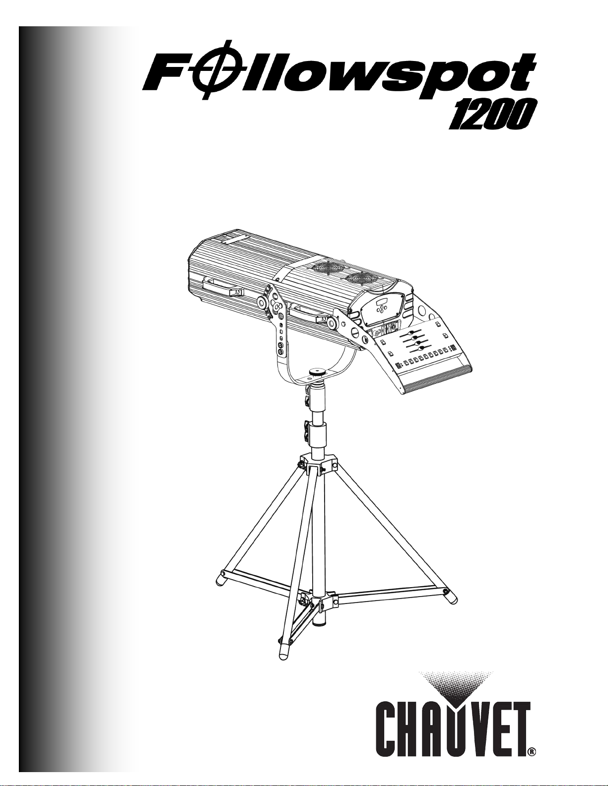
Page 1
User Manual
Page 2

Edition Notes
Edition
Trademarks
Copyright
Manual
Document
Intended
pot 1200
Disclaimer
CHAUVET®
Document
supersedes all previous versions of this
Fixture at
Notes
Notice
Usage
Printing
Audience
Publications
Hot Line
Revision
CHAUVET® released this edition of the Followspot 1200 User Manual Rev. 05 in
March 2012.
The F ollows pot 1200 User M anual Rev. 05 covers the desc ript ion, s afety pr ecautions,
install ati on, progr am mi ng , op eration and m aintenanc e of the Followspot 1200 .
CHAUVET® is a regist ered tr ad emar k of C HAUVET & S ons Inc. (d/b/a CHAUVET ® or
Chauvet). T he CHAUVET ® logo in its entirety inc luding the C hauvet nam e and the
dotted triangl e, and all oth er trad emarks on this manual pert ain ing to servic es, pr oduc ts
or mark eting statements (exam ple: It’s Gr een Thinking™) are owned or lic ensed by
CHAUVET®. Any other product names, logos, brands, company names, and other
trademarks featured or referred to within this document are the property of their
respective trademark holders.
CHAUVET® owns the content of this user manual in its entirety, including but not
limited to pictures, logos, trademarks and resources.
© Copyright 2012 CHAUVET®
All rights reserved
Elec tronically publi s hed by CHAUV ET® in the Un it ed S t at es of Am erica
CHAUVET® authorizes its customers to download and print this manual for
professional information purposes only. CHAUVET® expressly prohibits the usage,
copy, st orage, dis tribu tion, modific ation or printing of this m anual or its cont ent for any
other pur p os e wi th ou t its wr itten consent.
For bett er results , print t his docu ment in c olor, on let ter siz e pap er (8.5 x 1 1 inches),
doubl e sided. If us ing A4 p aper (210 x 297 mm), c onfigure your printer t o scale t he
content of th is doc u m ent to A4 paper.
Any person in ch arge of installing, op erating and/or main taining the Follows
should r ead the Qu ick St art Guid e that s hipped wit h the Fol lows pot 1200 u nit an d this
manual in th eir ent irety befor e ins t alling, operating or mai nt ai n in g the Followspot 1200.
CHAUVET® believes that the inf ormati on contained in this manu al is accurate in all
respects. However, CHAUVET® assumes no res ponsibilit y for any error or omissions
in this d ocumen t. CHAU VET® r eserves t he rig ht to r evise th is docu ment an d to mak e
changes from time to time in the content hereof without obligation of CHAUVET® to
notif y any pers on or com pany of s uch revis ion or ch anges. This d oes not c onstitut e in
any way a commit men t by CHAUVE T® to mak e such changes. CHAUVET ® m ay iss ue
a revisi on of this manual or a new edition of it to incorpor ate such changes.
If you have an y comment s ab out the acc urac y of this doc um ent or gen er al sugg esti ons
regard ing how w e can impr ove it, pleas e call us at (800) 762-1084 (US callers) or +1954-929-1115 (interna tional ca llers), ext. 43.
You can download the latest versions of all CHAUVET® products’ manuals from
www.chauvetlighting.com.
The Followspot 1 200 Us er Manual Rev. 05
manual.
Please dis card any older versions of this man ual you may have, wh ether in print ed or
electron ic format, and replace them wit h this v er s i on.
Use on Dimmer
Auto Programs
a Glance
Outdoor Use
Sound Activated
DMX
Master/Slave
Follo wspot 1200 User Manual Rev. 5
208/230 V, 50/60 Hz
Replaceable Fuse
User Serviceable
Duty Cycle
Page 3

Table of Contents
Table of Contents
1. Before you Begin .............................................................................................................1
What is Included ............................................................................................................................. 1
Unpacking Instruc tions ................................................................................................................... 1
Text Conventions............................................................................................................................ 1
Icons .............................................................................................................................................. 1
Safety Notes ................................................................................................................................... 2
2. Introduction .....................................................................................................................3
System Description ......................................................................................................................... 3
Features ......................................................................................................................................... 3
Additional Features .................................................................................................................................... 3
DMX Channel Summary ................................................................................................................. 3
6-channel DMX mode ................................................................................................................................ 3
Product Overview ........................................................................................................................... 4
Product Dimensions ....................................................................................................................... 5
3. Setup ................................................................................................................................6
AC Power ....................................................................................................................................... 6
Power Requirements .................................................................................................................................. 6
Power Cord ............................................................................................................................................... 6
Fuse Replacement ..................................................................................................................................... 6
Voltage/Frequency Selection ...................................................................................................................... 7
Lamp .............................................................................................................................................. 8
Lamp Removal........................................................................................................................................... 8
Lamp Installation ........................................................................................................................................ 9
DMX Linking ................................................................................................................................. 10
DMX Connection ...................................................................................................................................... 10
Mounting ...................................................................................................................................... 11
Orientation ............................................................................................................................................... 11
Rigging .................................................................................................................................................... 11
4. Operation .......................................................................................................................12
Control Panel Description ............................................................................................................. 12
Programming Panel ................................................................................................................................. 12
Navigation Functions ................................................................................................................................ 12
Followspot 1200 Menu Options ..................................................................................................... 13
Normal Mode ........................................................................................................................................... 13
Offset Mode ............................................................................................................................................. 13
Programming Procedure ............................................................................................................... 14
Normal Mode ........................................................................................................................................... 14
Normal Mode (Cont.) ................................................................................................................................ 15
Offset Mode ............................................................................................................................................. 15
External Console .......................................................................................................................... 16
Controls ................................................................................................................................................... 16
DMX Controller Oper ation ............................................................................................................. 17
DMX Values ................................................................................................................................. 17
6-CH........................................................................................................................................................ 17
5. Technical Information ...................................................................................................17
Maintenance ................................................................................................................................. 17
Returns ........................................................................................................................................ 18
Claims .......................................................................................................................................... 18
Contact Us ................................................................................................................................... 18
Technical Specifications ............................................................................................................... 19
-a- Follo wspot 1200 User Manual Rev. 5
Page 4

Page 5
1. Before you Begin
Unpacking
have to return the fixture to the factory, you will have to do so in its original flight case,
Text
1~512
A range of val u es
50/60
A set of mutually exclusive values in the text
[10]
A DIP switch to be configured
Claims
A fixture function, a new term, a s ection or a chapter
“COLORado™ UM”
The name of another publication or manual
<SET>
A key to be pressed on the fixture’s control panel
Settings
A menu option that can be selected but not modified
MENU > Settings
A sequence of menu options to be followed
[1~10]
A range of m enu val u es of w hich one can be s elected
Yes/No
A set of mutually exclusive menu opti ons to choose
ON
A value to be entered or s el ect ed
Icons
This icon indicates critical ins tallation, config uration or op eration
party equi pment, or cause harm to the user.
What is
Included
Instructions
Conventions
• One Followspot 1200 Fixture
• One External Console
• One Tripod
• One Flight Case
• Warranty Card
• Quick Reference/Start Guide
The Followspot 1200 ships in a flight case, Immediately upon receiving the fixture,
carefully unpack the flight c ase. Ch eck the f light c ase cont ents t o ensure t hat all part s
are present and that they ar e in good condit ion. If any p art appears d amaged from
shipping, or if the flight case shows signs of mishandling, notify the shipper
immediately. In addition, retain the flight case and all the packing material for
inspection.
In any event, s ave the f light cas e and all p acking material because, in case t hat you
with all its original packing. See the Claims section in the Technical Information
chapter.
Convention Meaning
Before you Begin
Icons Meaning
information. Failure to comply with this information may render
the fixture partially or completely inoperative , damage third-
This icon indicates important installation or configuration
information. Failure to comply with this information may pr ev en t
the fixture from functioning correctly.
Useful information.
-1- Follo wspot 1200 User Manual Rev. 5
Page 6
Before you Begin
Safety
Notes
carefully because they include important safety
There are no user-servic ea ble parts i n si d e t h e Fo llo w spo t 1 2 00. A ny r eferenc e to
any repairs unless you are one of them.
Please read the following notes
inform at i on ab ou t th e inst allation, usage and m ai nt enance of this pr o duc t.
It is important to read all these n ot es before st arti ng to work wit h this product.
servicing thi s unit y ou m ay fin d fro m no w on in thi s U ser Manu al wil l only apply
to properly CHAUVET® c ertified techn ici an s. Do n ot op en t he h ous ing or atte mp t
Please refer to all applicabl e local codes an d regulations f or proper inst allation
of the Followsp ot 1200.
Keep this manual for future consultation. If you sell the Followspot 1200 to
another user, make sure that they also receive this manual.
• The Foll ow s p ot 1200 hous i ng w eig hs 94 lbs (42.6 kg). Always ask for help when
mounting this fixture to avoid personal injuries or damage to the unit.
• Always connect the Followsp ot 1200 to a grounded circuit to avoid the risk of
electrocution.
• Avoid direct eye exp os ure to the ligh t s ource while th e Followspot 1200 is on.
• Lamp explosion hazard! Do not open the lamp cover within five minutes of having
turned off the fixture.
• The bulb remains hot for a long time after turn off. Never touch the bulb
barehanded and always hand it by its metallic contacts.
• Always disconnect the Followspo t 1200 from its power source before servicing.
• Do not touc h th e Followspot 1200’s housing when op erating b ec ause it may reac h
up to 85º C.
• This product is for indoor use only! To prevent risk of fire or shock, do not expose
this produc t t o r ain or m oistur e.
• Make sure there are no flammable materials close to the fixture(s) while operating.
• When hang in g this fixture, always secure it to a fastening device using a safety
cable (not prov ided).
• Maximum ambient temperature (Ta) is 104° F (40° C). Do not operate the fixture at
a higher temperature.
• Always m ak e sure that you are c onn ec t i ng th e Followspot 1200 to the proper
voltage, as per the specifications in this manual or on the product.
• Never connect the Foll ow s p ot 12 00 to a dimmer pack.
• Never disconnect th e pow er t o the f i xture by pullin g or t ug gi ng on t h e pow er c abl e.
• Make sure the power cord is not crimp ed or d am aged.
• In case of a serious operating problem, stop using this product immediately!
In the unlikely event that your Followspot 1200 may require service, please
contact CHAUVET® Technical Support.
Follo wspot 1200 User Manual Rev. 5 -2-
Page 7

2. Introduction
Description
Features
1
Shutter
2
Iris 3 Color
4
Color temperature
5
Dimmer
6
Focus
System
Additional Features
Introduction
The Fol l ows pot 1200 is a DM X compatibl e follow s p ot fixture that us es a 1200 W m et al
halide l amp and features a hi gh eff iciency optical ass embl y, a hi g h qu ality dichroic c ol or
wheel and an external c onsole.
This f ixture consis ts of a h ous in g unit that cont ains the p ow er s upply, the control panel,
the lamp and th e optical assembl y. The housing has a yoke f or trip od mounting. Th e
Followspot 1200 ships with an external console already mounted on its handle. In
additi on, t h e Followspot 1200 includes a stand-alone, adj ustable h eight tripod .
The 5-pi n DMX inp ut an d output s ock ets for D M X connecti vit y are on t h e c ont rol panel,
while there is another 5-pin XLR socket dedicated to the external console. The
Followspot 1200 features a bright 4-digit display and four buttons to perform all its
programming functions.
The ext ernal console f eat ures four sliders and sev er al buttons to control the f i xture in a
stand-alone fashion. However, th e user can conn ect th e Followspot 1200 to a DMX
daisy chain data link t o c ontrol it fr om a st an dard DMX c ontroller , al ong with oth er DMX
compatible fixtures.
• Metal Halide 12 00 W lamp
• 6-Channe l DMX mode
Functions: shutter, iris, color, color temperature, dimmer and focus
• Color Wheel 1
8 dichroic colors + white
Rainbow color spin at variable speeds
Split/Linear Colors
• Color Wheel 2
2 dichroic colors + white
CTC filter: 3,200 K / Frost / Open
• Variable electronic iris (4~38⁰)
• Variable electronic dimmer (0~100%)
• Variable electronic focus
• Blackout shutt er bu t t on
• External control console
• Tripod
• Flight case
DMX Channel Summary
6-channel DMX mode
-3- Follo wspot 1200 User Manual Rev. 5
DMX Channel Function
Page 8
Introduction
For detail s about the Contr ol Panel, refer to th e Fuse Replacement and DMX
the Operation chapter.
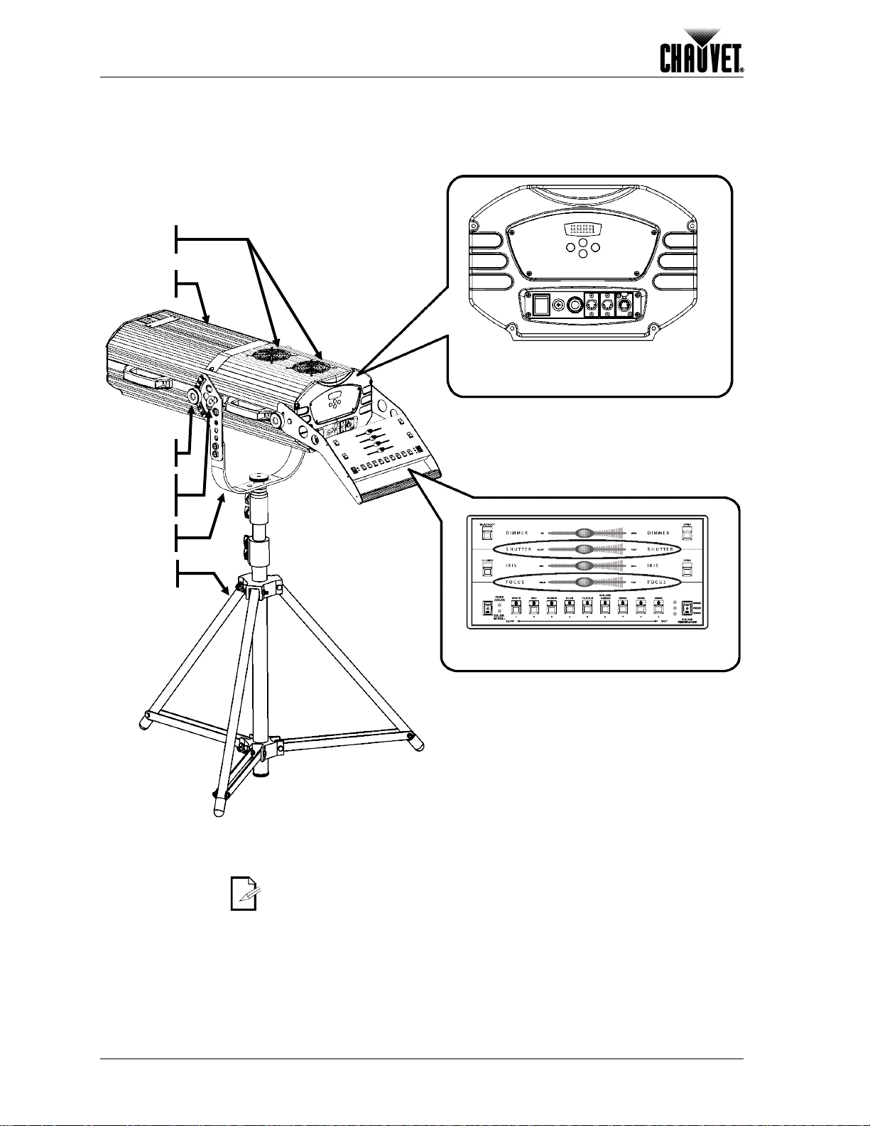
Housing
Fans
Yoke
Tripod
Safety
loop
Knob
Control Panel
External Console
Product Overview
Linking sections in the Setup chapter as well as the Operation chapter.
For deta ils ab out the exter nal co nsole, refer to the Exter nal Co nsole se ction of
Follo wspot 1200 User Manual Rev. 5 -4-
Page 9

Introduction
Product Dimensions
-5- Follo wspot 1200 User Manual Rev. 5
Page 10

Setup
Voltage and Frequency
see the label affixed to
Power Cord
Connection
Wire (U.S.)
Wire (Europe)
IP-66 Pin
Screw Color
AC Live
On/off Switch
Fuse Holder
Power Cord
Rubber Boot
3. Setup
AC Power
Power Requirements
Power Cord Pin Out
The Foll owspot 12 00 h as t w o AC i nput voltage settings, 208 and 23 0 V AC , and two AC
frequenc y setti ngs, 50 and 6 0 H z . T he voltag e an d frequ ency settings require changi ng
the c onnections on th e corres ponding termin al strip . See the
Selection sect i on in th is ch apter.
Always connect the Followspot 120 0 to a protected circuit with an appropriate
electrical ground to avoid the risk of electrocution or fire.
To deter min e the pow er requir emen ts for the Fol lowspot 12 00
the fixture. Alternatively, you may refer to the specifications chart in the Technical
Information chapter of this manual.
The list ed curr ent ratin g indic ates the m aximu m curren t draw dur ing normal op erati on.
Please r efer t o th e Sizin g the Circuit Breakers sect ion in the Appendix chapt er of this
manual.
The fi xture side of th e Followspot 1200 ’s power c ord enters t h e c ont rol panel thr oug h a
strain r elief boot. T his sid e of the pow er cord is hard-wired t o the fixture. Ther efore,
there is no removable power connector on the control panel.
The outl et side of th e power cord is bare -ended. This way, the users will be able to
equip it with the power plug that best matches the local standards and regulations.
Black Brown 1 Yellow or Brass
AC Neutral
AC Ground Green/Yellow Green/Yellow 3 Green
White Blue 2
Silver
Never co nnect the Foll owspot 1200 to a rheost at (variable r esistor) or dimmer
circuit, even if the rheostat or dimmer channel serves only as a 0 to 100% switch.
Fuse Replacement
Fuse Holder Diagram
1) With a Philips sc rewdriver, unscr ew th e f use holder out of its h ous ing and remove
the blown fuse from its holder.
2) Replace the bl ow n fuse with a fuse of the exact same type and rat i ng .
3) Replace the fuse holder in its place, and reconnect power.
Make s ure t o di sco nnect th e fi xtur e’s pow er cor d befo re r epl aci ng a b lo wn fu se,
and always replace it with a fuse of the same type and rating.
Illuminated
Follo wspot 1200 User Manual Rev. 5 -6-
Page 11

Voltage/Frequency
Selection
Do not connect the fixture to the power outlet without having selected the
matches your selection to avoid unstable operation or damage to the fixture.
ening the
A
TS
BC B FC
T
The Foll owspot 1200 uses a singl e terminal st rip to select th e operating voltage an d
frequenc y. This operation only requires connecting two wires to a terminal strip, as
indicated below.
voltag e and frequ ency first. Make sure t hat the cir cuit’s volt age and freq uency
Make sure that there is no power applied to the fixture before op
fixture’s housing.
Setup
Opening the Fixture
Cover Removal
Diagram
1) Unfasten the thumbscrew (T) and slide the front cover (FC) slightly forward.
2) Unscrew the two Allen screws (A) and remove the bracket (B).
3) Carefully pick up and slide the back cover (BC) backward, making sure not to pull
the wires that run from its fans to the Fan Control PCB inside the housing.
Two blac k wires arri ve to the ter minal stri p (TS). One wir e labeled “1” and the oth er
labeled “2.”
1) Connect the black wires as needed per the table below, without reversing them.
2) Replace the covers.
3) Replace the bracket and secure it with the two Allen screws.
Voltage/Frequency
Terminal Strip
Voltage/Frequency Wire #1 Wire #2
208 V, 50 Hz Terminal #2 Terminal #4
Voltage/Frequency
Selection Table
208 V, 60 Hz Terminal #2 Terminal #3
230 V, 50 Hz Terminal #1 Terminal #6
230 v, 60 Hz Terminal #1 Terminal #5
-7- Follo wspot 1200 User Manual Rev. 5
Page 12

Setup
Lamp
Lamp Removal
T
FC
LC
L
The user may ha ve to inst all the lamp b ef ore oper atin g the F ol l ows p ot 1200 f or th e f i rs t
time.
The instruc tions b el ow i nc lu de the steps to remove an exis ting lamp as w ell as t o ins tall
a new lamp.
Removi ng an alr eady i nst alled l amp r eq uires c aut ion. Foll ow t he st eps ind ic ated b el ow
to complete the removal in a safe manner.
Make sure that there is no power applied to the fixture before opening the
fixture’s housing.
Lamp explo sion hazard! Wait 15 minutes after having turned off the fixture to
open the lamp cover.
Opening the Fixture
1) Unfasten the thumbscrew (T) and slide the front cover (FC) slightly forward.
2) Loosen the thumbscrew that hold the lamp cover (LC) and lift it to expose the lamp
Lamp Removal
Diagram
Alway s w ear safety goggles and soft gloves when handling the lamp.
The bulb remains hot for a long time after turn off.
Never touch the bulb barehanded and always hand it by its metallic contacts.
Removing an
Existing Lamp
1) Once you ha ve ac cess to the l am p , loosen both l am p en d sc rews.
2) Grab the lam p b y both lamp end sc r ews , pus h it ev en l y ag ains t t h e cl ips and t h en
3) Place the lamp in an appropriate container for disposal.
Always follow local regulations regarding the disposal of used metal halide
lamps.
socket.
slide it upwards until it is free.
Follo wspot 1200 User Manual Rev. 5 -8-
Page 13

Lamp Installation
Installi ng a new lamp r equires caut ion. Follow t he steps indic ated below t o complete
If you touc hed the lamp with yo ur bare han ds, mak e sure to clean it thor oughly
shorten its life and even cause damage to the optical assembly.
Ensu re that the flat washers on the lam p shafts are on the thumbscrew side of the
Lamp Installation
Reflector
Lamp end
screw
Lamp end
screw
Bulb
nipple
Contact
plate
Clip
Clip
Fixture’s
front
Lamp
contact
Contact
plate
Flat
washer
the lamp installation in a safe manner.
(contacts, gla ss nec ks and glass globe) with is opro pyl alcoho l and wip e it with a
lint-free cl oth before installi ng it. Otherwise, the fingerprints on the lamp may
Follow all the safety instructions indicated on page 8.
Setup
Installing a
New Lamp
Diagram
1) If installing a new lamp, open the Followspot 1200 as indicated on page 8.
2) Befor e inst al ling the lamp, loosen its end sc rews.
3) Hold the lamp by its metallic contacts and slide it into the slots.
4)
slot to ensure maximum contact.
5) Evenly push the clips backward to allow the lamp to go all the way into the slots.
6) Rotate the lamp until the nipple is on the top of the bulb.
7) Tighten the lamp end screws.
8) Once installed, the lamp should look as in the diagram bellow.
Closing the Fixture
1) Close the lamp cover and tighten the thumbscrew that holds it.
2) Slide the front cover backward unt il it touches the bracket.
3) Tighten the thumbscrew to secure the front cover.
-9- Follo wspot 1200 User Manual Rev. 5
Page 14

Setup
DMX Linking
n link them using a
channel DMX
Pins 4 an d 5 of the E xternal C onsole Only socket car ry power f or the exter nal
you could damage the DMX controller or the fixtures connected to the DMX link.
connect the
External Console Only
DMX Input
DMX Output
If you are us ing th e F ollows p ot 12 00 wit h a D MX c ont roll er, you c a
regular DMX s erial connection. Be aware that th e Followspot 1200 uses 5-pin XLR
connectors and th at you wi ll need a 5-pin to 3-pin adapter in most cases.
If y o u are n o t fa m iliar wit h th e DMX standard, please refer to t he DMX Pr imer and DMX
Connectivity sections in the Appendix chapter of this m anu al .
The Followspot 1200 does not support the Master/Slave mode.
DMX Connection
DMX Connectors Diagram
The Followspot 1200 us es the regular DMX data connec ti on for its only 6mode. Ref er to t he Introduction chapt er for a brief d escri ption of this mode and th e
Operation chapter to learn how to configure the Followspot 1200 to work in t his mode.
The diagram below shows the Followspot 1200 DMX connectors.
console. Therefore, D O NOT con nect the DMX cable to this socket. Oth erwise,
1) Connect the DMX cable that comes from the DMX controller or from the other DMX
fixtures to the DMX Input socket.
2) Connect the DMX cable that goes to the other DMX fixtures to the DMX Output
socket.
When using the Followspot 1200’s external console, DO NOT
Followspot 1200 to the DMX link.
The diagram below illustrates a typical DMX link connection.
DMX Link Diagram
Follo wspot 1200 User Manual Rev. 5 -10-
Page 15

Setup
sure that there is adequate
. CHAUVET
Tripod
leg
Carrying
(both sides)
Yoke
Swivel
tripod top
Safety loop
(both sides)
Tilt
(+45 ~-45º)
Mounting
Orientation
Rigging
Product
Mounting
Diagram
Always m ount this fixtur e in any s afe pos iti on whi le m aking
room around it for ven til ation. M ak e s ure to mount th is fixture awa y f r om an y fl ammable
material as indicated in the Safety Notes.
The Followspot 1200 consists of a housing unit and a tripod (included)
recommends following the general guidelines below when mounting the Followspot
1200 and its tr ip od on top of a su it ab le platfor m.
• When sel ect in g an install at i on l oc ation, consi d er ease of access to the f i xture for
operation, progr am m in g adjustm ents an d routin e m ain tenanc e.
• Never mount the fixture in places where rain, high humidity, extreme temperature
chang es or res t ric ted ventil at i on m ay affect it.
• Make sure that the location where you are mounting the fixture can support its
weight (84 lbs / 38 kg) as well as th e operator’s w eig ht.
handles
adjustment
knob
As an ext ra me a sure to re duce v ibr ati on s and to pr eve nt th e fi xtur e fro m tipping
over, weight down the tripod arms or anchor them to the mounting platform.
-11- Follo wspot 1200 User Manual Rev. 5
Page 16

Appendix
digit blue LED display and four buttons located directly under the LE D display .
Programming
<ENTER>
Display
until the desired function shows on the
value on the display. Otherwise, the display will exit the current function without saving
4. Operation
Control Panel
Description
Panel
The Followspot 1200’s control panel includes the Programming Panel, the Power Panel
and the DM X Pan el. Ref er t o page 6 f or a descr ipt ion of the P ower P anel , and to p age
10 for a description of the DMX Panel.
The Pr ogramming P anel al lows the us er to conf igure th e Follows pot 1200’s functions
with a 4-
The table b elow explains t h e func tions of thos e bu t t ons .
Button Function
<MENU>
<UP>
<DOWN>
Used to scroll to a function or to
return t o a previous men u option
Selects a men u option
Scrolls through the menu
options in ascending (forward)
order
Scrolls through the menu
options in descending
(backward) order
Navigat io n Functio ns
Function Change
Function Selection
Function Value
Saving a Value
Function Timer
Programming Modes
The Followspot 1200’s navigation functions allow the user to setup all the fixture’s
parameters, as described in the Menu Map and the programming procedures.
The Followspot 1200’s display has four 7-s eg m ent , bl u e LED modul es .
To sel ect a f u nc ti on, press <MENU> repeatedly
display.
Altern ati vely, if the disp l ay s h ow s a functi on name, y ou could pr es s <UP> or <DOWN>
to look for another function.
To select a function, press <ENTER>. The display will start blinking.
To exit the current func t i on wi thout maki ng an y c h ange, press <MENU>.
Press <UP> or <DOWN> t o sel ect a val ue f or the cur rent f uncti on while t he displ ay is
blinking.
While th e display is bl in ki ng, press <ENTER> to save t h e s el ected valu e for the cur r ent
function.
After s el ect ing a functi on value, you h a ve eight sec onds to pr es s <ENTER> to sav e the
the new value.
The Followspot 1200 has two programming modes, Normal and Offset. Th e Nor mal
mode is for regular operation, while the Offset mode is for home adjustments.
Follo wspot 1200 User Manual Rev. 5 -12-
Page 17

Followspot 1200 Menu Options
Function
1st Level
2nd Level
Description
Normal Mode
Function 1st Level 2nd Level Description
Appendix
DM X A ddres s
Color Black Out
Self-test
Fixture Hours
Lamp On/Off
Reset
Offset Mode
Color Offset
Effect Offset
Dimmer O ffset
1~255 Selects the fixture’s DMX address
Yes/No Enables/disables the black out while changing colors
N/A Runs the built-in self-test program
N/A Shows th e am ou nt of h ours the fixtur e has been on
On/Off Turns the lam p on or off
N/A Resets the fixture to its factory default settings
-127~127 Performs the fine position adjustment for the color wheel
-127~127 Performs the fine position adjustment for the effects wheel
-127~127 Performs the fine position adjustment for the dimmer
-13- Follo wspot 1200 User Manual Rev. 5
Page 18

Appendix
Programming
Procedure
DMX Address
Color Wheel Blackout
Self-test
The Followspot 1200 programming requires only three menu level s and it uses t wo
programming modes, Normal and Offset.
The Off s et mod e is for home adjus t m en ts of the color, the dimmer and the effects.
When not in program mode, the display shows the current DMX address.
Normal Mode
The Nor mal mode contr ols the DMX addr ess, t he control ac tivation, the l amp on/off
status, the running of the self-tes t a nd the fixture reset. I n addition, it s h ows th e nu mb er
of hours the fixture has been in service.
Defines the fixture’s starting address
1) Press <MENU> repeatedly until the display shows
2) Press <ENTER> to show the current DMX address (1~255).
The display will start blinking.
3) To exit wit h out ch anging the val ue, press <MENU>.
4) To change the address val u e, pr ess <UP> or <DOWN>.
5) To save th e new val u e, press <ENTER>.
The display will show the next function name.
Enables/disables the blackout fixture wh ile changing colors
1) Press <MENU> repeatedly until the display shows
2) Press <ENTER> to show the current setting (Yes/No).
The display will start blinking.
3) To exit with out ch anging the value, press <MENU>.
4) To change the se tting, press <UP> or <DOWN>.
5) To save the new val u e, press <ENTER>.
The display will show the next function name.
Runs the built-in self-tests
1) Press <MENU> repeatedly until the display shows
The display will start blinking.
3) Press <ENTER> to start th e tests.
The display will stop blinking and the tests will start to run continuously.
5) To suspend the tests for 30 seconds, press <ENTER>.
6) To terminate the tests, press <MENU>.
The display will show the next function name.
Follo wspot 1200 User Manual Rev. 5 -14-
Fixture Hours
Shows the number of hours the fixture has been in service
1) Press <MENU> repeatedly until the display shows
The display will start blinking.
2) Press <ENTER> to see the number of hours.
3) To ex it, press <MENU>.
The display will show the next function name.
Page 19

Normal Mode (Cont.)
Lamp
Reset
lor wheel, the effects (color
Color Offset
Effect Offset
Appendix
Turns the lam p on or off
1) Press <MENU> repeatedly until the display shows
The display will start blinking.
2) Press <ENTER>.
The display will show the current lamp status (On/Off).
Lamp Off
3) To turn the lamp off, press <UP> or <DOWN> until the display shows off.
4) Press <ENTER> to save the change.
The display will st op bl in ki ng and the lamp wi ll turn off immediately.
In eight seconds, the display will start showing the current DMX address.
Lamp On
5) To turn the lamp on, press <UP> or <DOWN> until the display shows on.
6) Press <ENTER> to save the change.
The display will st op bl in ki ng and the lamp wi ll st ar t t o tur n on i mm ed iately.
In eight seconds, the display will start showing the current DMX address.
Resets all the settings to their factory defaults
1) Press <MENU> repeatedly until the display shows
The display will start blinking.
2) Press <ENTER> to start the defaulting process.
The display will stop blinking and it will show 1200.
All DMX channels will return to their default settings.
The reset fun cti on doe s not aff ect the Fixture Hours total.
Offset Mode
Entering Offset Mode
The Offset mode provides fine position adjustment for the co
temperature) wheel and the dimmer. These fine adjustments allow the operator to
positi on th e wh eels s o th e lig ht goes thr oug h th e cent er of th e c olor or eff ect apert ur e,
thus preventing any filter border from showing. In the cas e of the dimmer, the f ine
adjust m ent ens ures that at 0 % dimmer (m aximum l ig ht) , the dimm er is n ot affecting t h e
light beam .
1) Press <MENU> for five seconds.
The display will show the first offset mode function.
Performs the fine position adjustment for the color wheel
1) Press <UP> or <DOWN> repeatedly until the display shows
2) Press <ENTER>.
The display will start blinking, showing the current value (-127~127).
3) Press <UP> or <DOWN> to set the new value.
4) Press <ENTER> to s ave th e new val u e or <MENU> to exit without s a vi ng.
Performs the fine position adjustment for the effects wheel
1) Press <UP> or <DOWN> repeatedly until the display shows
2) Press <ENTER>.
The display will start blinking, showing the current value (-127~127).
3) Press <UP> or <DOWN> to set the new value.
4) Press <ENTER> t o s ave th e new val u e or <MENU> to exit wit hout savi ng.
-15- Follo wspot 1200 User Manual Rev. 5
Page 20

Appendix
Offset Mode (Cont.)
Dimmer Offset
Pins 4 and 5 of the Ext ernal Con sole Only so cket carry power for t he external
you could damage the DMX controller or the fixtures connected to the DMX link.
Controls
ider control by gently touching the slider. Resuming slider control after
ion on the left side, while the right side has another
minimum or opening it to
The slider operation can resume by slightly touching the slider after having set the iris
Exiting Offset Mode
External
Console
Performs the fine position adjustment for the dimmer
1) Press <UP> or <DOWN> repeatedly until the display shows
2) Press <ENTER>.
The display will start blinking, showing the current value (-127~127).
3) Press <UP> or <DOWN> to set the new value.
4) Press <ENTER> t o s ave th e new val u e or <MENU> to exit wit hout savi ng.
1) After you are done, wait ei gh t seconds f or th e dis pl a y tim er t o activate.
The display will show the current DMX address.
The external console ships already installed on the Followspot 1200 handle. This
console has dedic at ed sli ders and buttons to control only the associ at ed fixture.
In additi on, th e exter n al c onsol e c onnects to th e F oll owsp ot 12 00 us ing a d edic ated 5pin XLR connector on the control panel.
console. Therefore, D O NOT con nect the DMX cable to this socket. Oth erwise,
The ext ernal cons ole cont rols h ave pre-assigned functions and l abels. T his sim plifies
the fixture’s operation.
When the Followspot 1200 is in any of its programming modes, the external
console i s not op er ational.
External Console Diagram
Dimmer
Shutter
Iris
The dimm er has a Blac kout and an Open but ton. This allows the oper ator t o keep the
slider at a fixed positi on wh en c l osi ng t h e di m m er t o 0% or opening it to 100%.
When the dimmer is open after having pressed the Open button, the operator can
res um e the sl
blacking out the dimmer is not possible, howev er.
The shu tter has no fixed position buttons to operat e along with th e slider. T his slid er
has a closed and an op en posit
open pos iti on .
The shu tter freq u enc y chang es f rom s hort y et s eparat ed open ings to a f ast str obe-like
action as the slider moves from left to right.
The iris has a Closed an d an Open but t on. A s with th e dimm er, this all ows the operat or
to keep the slider at a fixed position whe n c losing the iris to its
its maximum.
to either its maximu m or mi nimum apert ure by using the corresponding bu tton.
Focus
Color Control
Color Temperature
Follo wspot 1200 User Manual Rev. 5 -16-
The focus control has no fixed b uttons to op erate along t he slider, either. Th e focus
changes from near to far as the slide r moves from left to right.
The button on the left lower corner of the console determines the way the color
chang es. If it is in th e Fix ed Col or p ositi on, b uttons 1 to 9 d et ermin e th e color . If it is in
the Color Scroll position, buttons 1 to 9 determine the scrolling speed (slow to fast).
The c olor t emper atur e c ontr ol is ind ep end ent f r om the c ol or c ontr ol m ode. It h as t hr ee
positi ons , 60 00º K, Frost and 32 0 0º K.
Page 21

DMX Controller
Operation
page 10 of this m anu al.
DMX Values
000 007
248 255
Blackout
Open
000 254
255
0~100%
Closed
000 014
192 255
White
CCW Rotation (Slow~Fast)
000 085
171 255
6,000 K
3,200 K
5
Dimmer
000 255
0~100%
6
Focus
000 255
Close~Far
Maintenance
minimize the contact with the mirror surface to a mini mu m.
6-CH
Appendix
To operat e the Fol lows pot 1 200 wi th a stan dar d DMX contr ol ler you will hav e to assi gn
a starting DMX address on the Followspot 1200. Please refer to the Programming
Procedure section of this chapter for instructions.
After th at, you wi ll h a ve t o c onnect the Followspot 1200 to the DMX li nk as i ndicated on
Always di sconn ect the extern al cont rol co nsole when oper atin g this fi xture with
a third party DMX controller.
Channel Function Value Percent/Setting
1 Shutter
2 Iris
3 Color
4 Color Temperature
008 015
016 247
015 028
029 042
043 056
057 070
071 084
085 098
099 112
113 127
128 191
086 170
Open
Strobe (1~12 Hz)
Red
Green
Blue
UV Purple
Golden Amber
2,900 K
4,800 K
3,800 K
CW Rotation (Fast~Slow)
5,600 K
5. Technical Information
To maintain optimum performance and minimize wear, the user should clean the
Followspot 1200 frequently. Usage and environment are contributing factors in
determi ning the c l eaning frequenc y. A s a rule, the user s h ould clean the f i xture at least
twice a month. Dust build-up reduces light output performance and can cause
overheating. This can lead to reduced light source life and increased mechanical wear.
The cleaning frequency depends on the environment in which the fixture operates.
Damp, s moky or particu larly di rty surr ounding c an caus e greater accumul ati on of dirt
on the uni t’s optics . Even in t he cleanes t type of sur roundin gs, the user shoul d clean
the extern al op tics at least onc e ever y 30 days . CHA UVET ® recom m ends c l ean ing the
fixture’s external opt ic s wit h a s oft cl oth us in g n or m al gl ass cleaning fluid.
To clean the Followspot 1200, follow the below recommendations:
• Unplug the fixture from power.
• Wait until the fixture is cold (15 minutes minimum).
• Use a vacuu m (or dr y c ompress ed air) an d a s oft brus h to remove du s t coll ec t ed
on the external vents and r eac h abl e intern al c omp on en ts .
• Clean all optics and gl ass surfaces with a mild solu ti on of gl ass cl eaner or isopropyl
alcohol, and a soft, lint free cotton cloth or a lens cleaning tissue.
• Apply the solution directly to the cloth or tissue and drag any dirt and grime to the
outsid e of the lens.
• Gently polish the glass surfaces until they are free of haze and lint.
• When cleaning movable mirrors, to avoid scratching or damaging their surface,
-17- Follo wspot 1200 User Manual Rev. 5
Always dry the optics and glass surfaces carefully after cleaning them.
If the fixture has fans, never spin them using compressed air.
Page 22

Appendix
Returns
its original
any related claims with the carrier, not
merchandise. Failure to do so in a timely manner may invalidate the customer’s claim
The user mus t send the merch andise prep aid and in the orig inal box with
packi ng a nd ac cess ori es. CHA UVE T® will not issue call tags.
Call CHAUVET® and requ est a Retur n Merch andise Au thorization Number ( RMA #)
before s hipping the fi xture. B e prep ared to provide t he mod el numb er, seri al numb er
and a brief description of the cause for the return.
The user must clearly label the package with a Return Merchandise Authorization
Number (RMA #). CHAUVET® will refuse any product returned without an RMA #.
DO NOT write the RMA # directly on the box. Instead, write it on a properly
affixed label.
Once you ar e given an RMA #, pl ease includ e the followi ng informat ion on a piece of
paper inside the box:
• Your name
• Your addr es s
• Your phone number
• The RMA #
• A brief description of the symptoms
Be sure t o pac k the fi xture prop erly. An y shippi ng dam age resu lting f rom inad equate
packaging is th e customer’s r esponsibility. As a sugges tion, prope r UPS packing or
double-boxing is always a safe method to use.
CHAUVET® reserves the right to use its own discretion to repair or replace
returned product(s).
Claims
Contact Us
Follo wspot 1200 User Manual Rev. 5 -18-
The carri er is resp onsible f or an y damage inc urred durin g shipping . Therefor e, if the
received m erchandis e ap pears to have dam ag es caused dur i ng shippin g, t he custom er
must submit the damage report and
CHAUVET®. The customer must submit the report upon reception of the damaged
with the carrie r.
For other issues such as missing components or parts, d am age not rel at ed t o shipping,
or conc eal ed damage, the cust om er must m ak e c l aims t o C H AUVET ® within seven (7)
days of rec ei vi ng t h e m erc handis e.
World Wide
General Inform ation
CHAUVET®
5200 NW 108th Avenue
Sunrise, FL 33351
Voice: (954) 929-1115
Fax: (954) 929-5560
Toll free: (80 0) 76 2-1084
Technical Supp or t
Voice: (954) 929-1115 (Press 4)
Fax: (954) 929-5560 (Attention: Service)
World Wide Web
www.chauvetlighting.com
Page 23

Technical Specifications
Weight & Dimensions
Length ................................................................................................................................. 45.1 in (1,147 mm)
Width ...................................................................................................................................... 16.9 in (430 mm)
Height ........................................................................................................................................9.0 in (230 mm)
Weight (Product only) ............................................................................................................... 94 lbs ( 42 .6 k g)
Weight (Stand) ............................................................................................................................ 17 lbs ( 7. 7 kg)
Weight (All w/ roadcase) ........................................................................................................ 213 lbs (96.6 kg)
Power
Select able Input V olt ag e and F r equenc y ......................................................................... 208/230 V, 50/60 Hz
Current draw ................................................................................................... Ope rating: 8.61 A; Inrush 9.2 A
Power .................................................................................................................................................... 1,264 W
Power Factor......................................................................................................................................... PF 0.71
Fuse
External ............................................................................................................. 6 x 30 mm, glass, 15 A, 250 V
Light Source
Metal Halide Lamp ................................................................. Osram HTI 1200 W /D /7/60, 6,500 K, 2,000 hrs
Quantity ............................................................................................................................................................ 1
Photo Optic
Luminance (4º angle) ......................................................................................................... 202,000 lux @ 1 m
Luminance (13º angle) .............................................7,000 lux @ 5 m ; 3650 lux 2 7 meter, 1800 lux @ 10 m
Beam angl e range .................................................................................................................................... 4~38°
Control & Programming
Data input .......................................................................................................... locking 3-pin XLR mal e s ock et
Data out put ....................................................................................................locking 3-pin XLR female socket
Data pin configuration....................................................................................... pin 1 shield, pin 2 (-), pin 3 ( +)
Protocols ................................................................................................................................. DMX-512 USITT
DMX Cha nnels ................................................................................................................................................. 6
Ordering Information
Follo wspot 1200............................................................................................................... FOLLOWSPOT1200
Appendix
-19- Follo wspot 1200 User Manual Rev. 5
Page 24

CHAUVET®
5200 NW 108
th
Avenue
Sunrise, FL 33351 (USA)
Toll fr ee (800) 762-1084, Local 954-929-1115
Fax 954-929-5560
www.chauvetlighting.com
Followsp ot 1200 User Manual-Rev. 5
© Copyr ight 2012 CHAUVET®
All rights reserved.
Printed in the P. R. C.
 Loading...