

Page 1
Getting Started User Manu al
Series
18
12
37.5
Page 2
Edition Notes
Trademarks
) are owned or
Copyright Notice
Manual Usage
CHAUVET® authorizes its customers to download and print this manual for
Document Printing
Disclaimer
assumes no responsibility for any error or
to make such
Document Revision
Author
Date
Editor
Date
Edition Notes
This User Manual covers the description, safety precautions, setup, installation,
operation, and mai ntenance for all 3 Modular Video Panel s offer ed by CHAUVET®.
This edition was published in January 2012.
CHAUVET® is a registered trademark of CHAUVET & Sons Inc. (d/b/a CHAUVET®
or Chauvet). The CHAUVET® logo in its enti rety including the Chauvet name and
the dotted triangle, and all ot her trademarks on this manual pertaining to servi ces,
products, or marketing statements (example: It’s Green Thinking™
licensed by CHAUVET® . Any other produc t names, l ogos, brands, c om pany names,
and other trademarks featured or referred to within this document ar e the property of
their respectiv e trademark holders.
CHAUVET® owns the cont ent of this user manual in its entirety, includi ng but not
limited to pictur es, logos, trademarks, and resources.
© Copyright 2012 CHAUVET®. All rights reserved.
Electronic ally published by CHAUVET® in the United States of America.
professional information purposes only. CHAUVET® expressly prohibit s the usage,
copy, storage, di stribution, modification, or printi ng of this manual or its content for
any other purpose without its writt en consent.
For best results, pri nt this document in col or, on letter size paper (8.5 x 11 i nches),
double sided. If using A 4 paper (210 x 297 mm), configure your print er to scale the
content accordingly.
CHAUVET® believes that the information contai ned i n this m anual is accur ate i n al l
respects. However, CHAUVET®
omissions in thi s document . CHAUVET® reserves the ri ght to revi se this docum ent
and to make changes f rom time to time i n the content hereof wit hout obligation of
CHAUVET® to notify any person or company of such revision or changes. This
does not constitute in any way a commitment by CHAUVET®
changes. CHAUVET ® m ay issue a revisi on of this manual or a new editi on of it to
incorporate such changes.
The MVP™ Seri es Get ting Start ed User Manual, Rev. 10, supersedes all previous
versions of this manual . Please discard any older versions of this manual you may
have, whether in printed or electronic format, and replace them with this version.
D. Couppe 2/14/12 S. Graham 2/14/12
MVP™ (12/18/37.5) Series Getting Started User Manual, Rev. 10
Page 3

Table of Contents
1. Before You Begin ............................................................................................... 1
What Is Included ............................................................................................................ 1
Unpacking Instruc tions ................................................................................................... 1
Claims ................................................................................................................................... 1
Typographic Conv entions ............................................................................................... 1
Icon Meaning ................................................................................................................. 1
Safety Notes .................................................................................................................. 2
Expected LED Lifespan .................................................................................................. 2
2. Introduction ........................................................................................................ 3
Product Description ........................................................................................................ 3
Features ........................................................................................................................ 3
Additional Features................................................................................................................. 3
Additional Products................................................................................................................. 3
Opt ional Acces sori es .............................................................................................................. 3
Available Signal and Power Cables (optional) .......................................................................... 3
Product Overview: MVP™ 12, MVP™ 18, and MVP™ 37.5 ............................................ 4
Product Dimensions ....................................................................................................... 6
MVP™ Pixels Per Panel ................................................................................................. 6
Table of Contents
3. Setup ................................................................................................................... 7
4. Mounting ............................................................................................................. 8
5. Joining Each MVP™ (Creating a Modular Design).......................................... 9
6. Connecting (Cabling) Each MVP™ ................................................................. 12
7. T y pical MVP™ Installation ............................................................................... 17
AC Power ...................................................................................................................... 7
AC Plug ................................................................................................................................. 7
Power Linking ........................................................................................................................ 7
Orientation ..................................................................................................................... 8
Truss Installat ion ............................................................................................................ 8
Vertically Joining the Panels ........................................................................................... 9
Horizontally Joining Panels ...........................................................................................11
Testing Signal and Power Connections .........................................................................12
Using the MVP™ Test Button ........................................................................................12
Connecting the Si gnal Input ..........................................................................................13
Connecting Power and Si gnal Cables............................................................................14
Connecting the Signal Between Joined Panels .................................................................... 14
Connecting the Power Between Joined Panels .................................................................... 16
Step 1 ...........................................................................................................................17
Step 2 ...........................................................................................................................17
Step 3 ...........................................................................................................................17
Step 4 ...........................................................................................................................17
Step 5 ...........................................................................................................................17
Step 6 ...........................................................................................................................17
Step 7 ...........................................................................................................................17
MVP™ Sample Video Wall System Setup .....................................................................18
MVP™ (12/18/37.5) Series Getting Started User Manual, Rev. 10 -i-
Page 4

Table of Contents
8. Operation .......................................................................................................... 19
Additional Har dware and Sof tware ................................................................................19
About LED Studio .........................................................................................................20
Description ........................................................................................................................... 20
9. Techni cal In f ormation ...................................................................................... 21
MVP™ Maintenance .....................................................................................................21
Troubleshooting User Manual .......................................................................................21
Returns Procedure ........................................................................................................22
Contact Us ....................................................................................................................22
10. Technical Spe ci f icati on s ............................................................................... 23
-ii- MVP™ (12/18/37.5) Series Getting Started User Manual, Rev. 10
Page 5
1. Before You Begin
What Is
• Two (2) or Six (6) MVPs (Modular Vi deo P anels) models 12, 18, or 37.5
One Getting Started User Manual
Unpacking
container. Make
notify the
Failure to do so in a timely manner may invalidate
within seven (7) days of receiving the
Typographic
1~512
A range of values in the text
50/60
A set of mutually excl usive values in the text
Italics
A reference to a secti on, chapter, or external document
<SET>
A button on the product’s control panel
Settings
A product function or a m enu option
MENU à Settings
A sequence of menu options
1~10
A range of menu values from which to choose in a menu
Yes/No
A set of two mutually ex cl usive menu options in a menu
ON
A unique value to be entered or selected in a menu
Icon Meaning
Icon
Meaning
Critical installation, configuration, or operation information. Failure
harm to the user.
Important installation or configuration information. Failure to
functioning c or r ectly .
• One Neutrik® etherCO N® Signal Cable per MVP™ 0.4 m/15.8 in
Included
Instructions
• One Neutrik® powerCON® Power Cable per MVP™ 0.4 m/15.8 in
• One 2- or 6-Pack Flight Case (based on the number of MVPs included)
• One Warranty Card
•
Immediatel y upon receiving t his product, caref ully unpack and check the
sure you have received all the parts indicated above in good condit ion.
Before You Begin
Claims
Conventions
Upon receipt, if the cont ai ner or the material i nside the contai ner (the product and included
accessories) appear damaged from shipping, or show signs of mishandling,
carrier immedi ately, not CHAUVET®.
your claim with the carri er. In addition, keep the container and al l the packing material for
inspection.
For other i ssues such as m i ssing com ponents or parts , dam age not rel ated t o shippi ng, or
concealed damage, file a claim with CHAUVET®
merchandise.
Convention Meaning
to comply with this information may render the product parti ally or
completely inoperative, damage third-party equipm ent, or cause
Useful, non-critical information.
comply with this information may prevent the product from
MVP™ (12/18/37.5) Series Getting Started User Manual, Rev. 10 -1-
Page 6
Safety Notes
damage or malfunction. Please contact CHAUVET® Technical Suppor t.
Expected LED
LEDs gradually decline in brightness over time, mostly because of heat. Packaged in
and reducing the
. In addition, limiting the overall
projection int ensi ty may also help to extend the LEDs’ lifespan.
Before You Begin
Please read the following Safety Notes carefully before starting to work with the product.
These notes provide important safety informati on about t he installation, usage, and
maintenance.
This product contains no user-serviceable parts. Any referen ce t o servi cing in this
User Manual will only ap ply to proper ly trained CHAUVET® certif ied technicians. Do
not open the housing or attempt any repairs.
Please refer to all applicable local codes and regulations for the proper ins ta llati on
of the product.
• Always connect the produc t to a grounded circuit to avoid the risk of electroc ution.
• The product is rated IP54 and shoul d only be used in environments meeting that
criteria.
• When hanging the produc t, always secure t o a fastening device using a safety cable.
• The maximum ambient temperature is 122° F (50° C). Do not operate the produc t at
higher temperatures.
• Do not operate the pr oduc t if you see damage on the housing, LED strips, or cables.
In any of these cases, have the damaged par ts replaced by an authorized technician.
• Do not open or modify the product.
• Make sure the product is connected to the proper voltage provided in this manual’s
specifications and/or the specification stic k er on the product.
• Never try to repair the product. Repairs carried out by unskilled people can lead to
Any damages caused by manual modi ficat io ns are not subject to warranty.
CHAUVET® will not accept liability for any resulting damages caused by
unauthorized modifications or not observing the safety warnings an d ins tructions
in the manual.
In the unlikely event that your CHAUVET® product may require service, contact
CHAUVET® Technical Suppo rt .
clusters, LEDs exhi bit higher operati ng temperat ures than in ideal, single LE D conditions.
Lifespan
For this reason, using clustered LEDs at their fullest intensity significantly reduces the
LEDs’ lifespan. The electrical, thermal management design of the MVP™ panel is
designed to provide the longest LED lifespan possible. Under normal operating conditions,
this lif espan can be 50,000 hours or l onger. If extending t his lifespan is vital, lower the
operational temperature by improving ventilation around the fixture
ambient temperature to an optimal operating range
-2- MVP™ (12/18/37.5) Series Getting Started User Manual, Rev. 10
Page 7

2. Introduction
Product
Features
Easily viewed during daylight oper ation
Features
Products
• MVP™ Driver (required)
Accessories
MVPU-SIG5FT
MVPU-SIG10FT
MVPU-SIG25FT
PCEXT5FT
PCEXT10FT
PCEXT25FT
PCLEAD50FT
Description
Setup
The MVP™ is a Modular Video Panel. The MVP™ series includes three models:
• MVP™ 12
• MVP™ 18
• MVP™ 37.5
Each model is a panel consisting of multiple LED full-color light strips. The num ber in eac h
model name indicates the pixel pitch (distance, in millimeters, between the LED light
strips) of that model. When multiple panels are assembled and connected (signal and
power), the entire configuration becomes a modular video wall design.
The outer dimensions of each panel are identical. T he difference between each m odel is
the spacing between the LED light strips and the number of LED pixels on each strip. Both
of these v alues determine the total num ber of LE D pix els provi ded on each panel. Each
pixel is one SMD5050 LED.
The aluminum all oy and stai nless steel construction make the M VP™ reliable and solid,
as well as easy to i nstall and dismantle. You can assemble multiple panels horiz ontally or
vertically, and each model is interchangeable with the others. This flexibility provides
numerous modular desi gn possibilities.
The MVP™ video wall system is controlled using a PC and the LED Studio software
available as download from the Internet. Refer to the LED Studio User Manual for
detailed information and instructions on using LED St udio.
• Packaged in a convenient CHAUVET® flight case that includes either two (2) or
six (6) MVP™ panels
• Lightweight, modular system
• Provides multiple graphics based on which MVP™ is used and how the video wall
is assembled
• Uses Neutrik® powerCON® and Neutrik® etherCON® connectors for easy
install ation and connectivity
• Perfect for long-term installations
• Each MVP™ is interchangeable for creative modular video wall designs
• Tri-color SMD LEDs provide bett er image quality and wider viewing angle
• Designed for indoor or tempor ar y outdoor installations
•
Additional
Additional
Optional
• One Neutrik® etherCON® signal cable per MVP™ 0.4 m/15.8 in
• One Neutrik® powerCON® power cable per MVP™ 0.4 m/15.8 in
• MVP™ 526P Signal Processor (processor required for alternate video sources)
• MVP™ Signal Distributor (required when using 25 MVPs or more in your video wall)
• MVP™ Rigging Kit (required when you hang panel s from a truss or truss structure)
Available Signal
and Power Cables
(optional)
MVP™ (12/18/37.5) Series Getting Started User Manual, Rev. 10 -3-
• Signal cables (Neutrik® etherCON® Signal Extensions)
•
•
• Power cables (Neutrik® powerCON® Extension)
•
•
•
•
•
Page 8
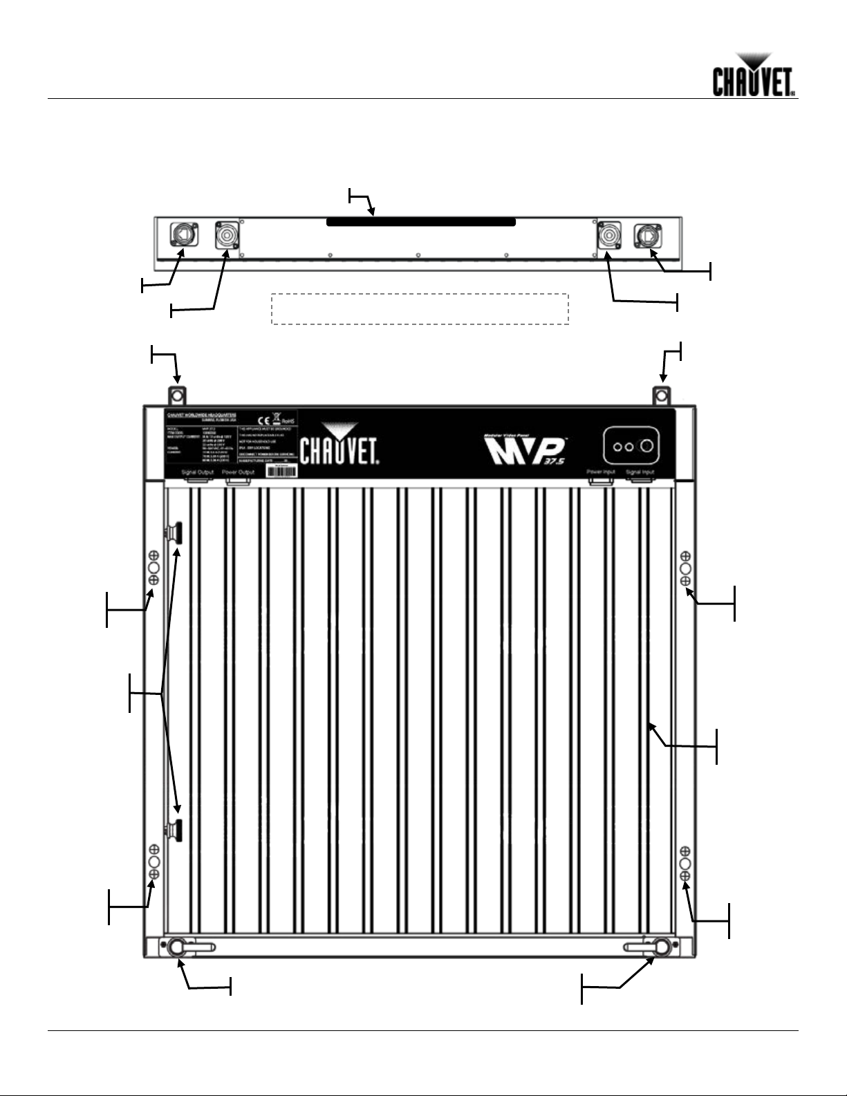
Signal Input
Power In put
Signal Output
Power Output
Vertical rigging
Rigging
Plate
Rigging
Plate
Rigging
Plate
Rigging
Plate
LED
Strip
Horizontal
locking knob
Fast Lock
Fast Lock
Handle
Vertical rigging
Underside of MVP™ Panel Ledge
Mounting the MVP s™
Product Overview: MVP™ 12, MVP™ 18, and MVP™ 37.5
-4- MVP™ (12/18/37.5) Series Getting Started User Manual, Rev. 10
Page 9
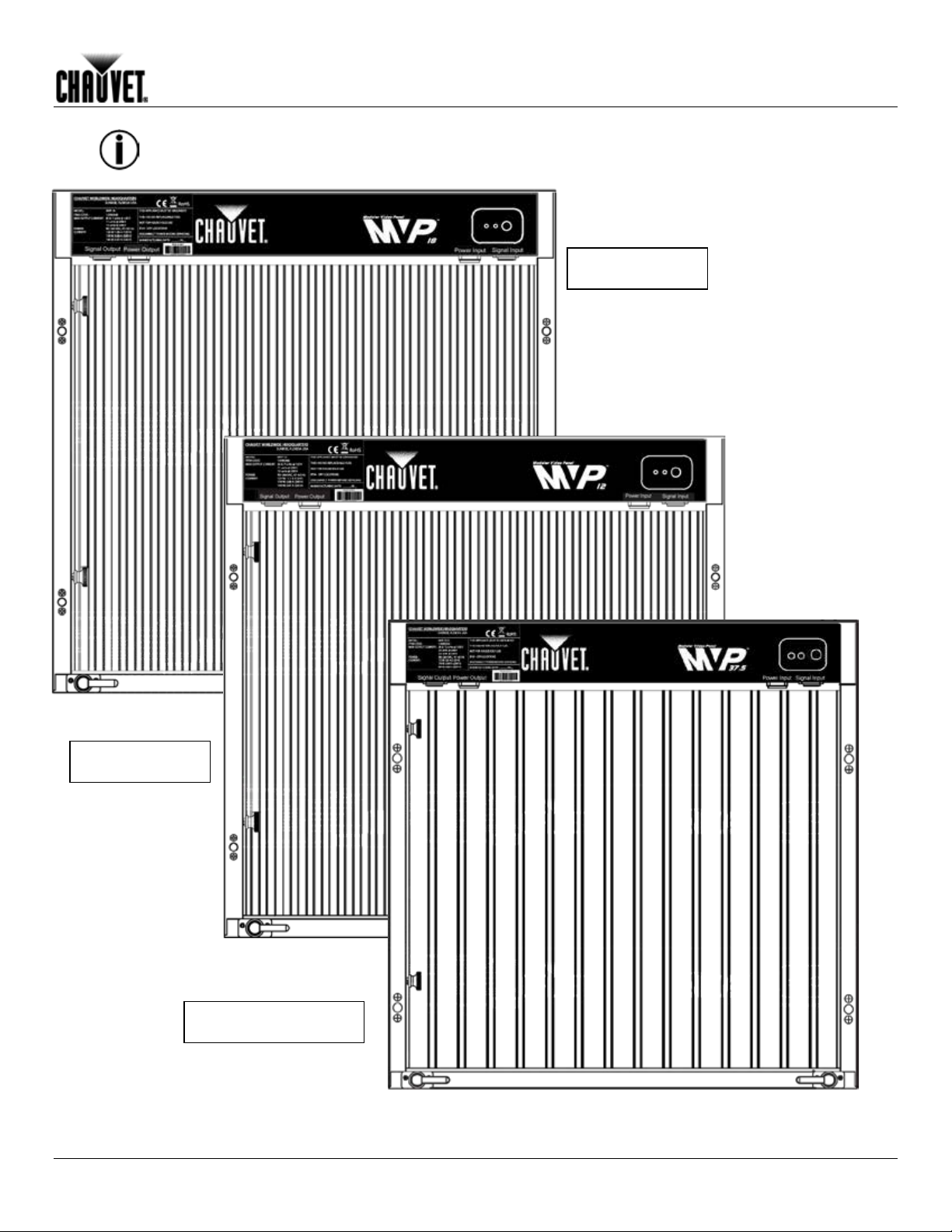
The differenc e between each MVP™ model is the pixel pitch (space) between the LED strips and the
MVP™ 18
MVP™ 12
MVP™ 37.5
number of pixels (LEDs) on each str ip. The basic housing and components are i dentical. Refer to the
previous MVP™ 37.5 illustration.
Setup
MVP™ (12/18/37.5) Series Getting Started User Manual, Rev. 10 -5-
Page 10

MVP™ Pixels
panel vary.
in each
MVP™ 12
MVP™ 18
MVP™ 37.5
horizontally and
Diagrams of how the MVP™ panels and the
23.6 in
(600 mm)
23.6 in
(600 mm)
Mounting the MVP s™
Product Dimensions
Each MVP™ model in the series has the same outside housing dimensions.
Although each MVP™ has the same outer dimensions, the LED pixels per
Each pixel is one SMD5050 LED. The following t abl e provides the pixels per panel
Per Panel
MVP™. The Series num ber (i .e., 37.5) indicates the pixel pitch in millimeters between each
light strip in that MVP™ model. For detailed specifications, refer to the Technical
Specifications table at the end of this User Manual.
-6- MVP™ (12/18/37.5) Series Getting Started User Manual, Rev. 10
Pixels per Panel 48 x 48 32 X 32 16 X 16
Total Pixels 2,304 1,024 256
You will use the number of pixels per panel and the screen resolut ion you would like to
use for your video wall display to calculate the number of panels,
vertically, supported by a single MVP™ Driver. This Driver is required to operate a
CHAUVET® MVP™ video wall system.
MVP™ Driv er operate together f ollow lat er in thi s manual. For detailed information about
the MVP™ Driver and panel calculation examples, refer to the MVP™ Driver Quick
Reference Guide.
Page 11

AC Power
with an input volt age range of
in this
eries, refer to the label
®
,
be purchased separately. CHAUVET® recommends the
available from
power
Refer to the following table for
3. Setup
Each MVP™ has an auto-rangi ng power supply that works
100~240 VAC, 50/ 60 Hz.
Make sure that you are connecting the MVPs to the proper v oltage, as specified
User Manual and on the produc t’s specification sticker.
Always connect this product to a protected circuit with an appropriate electrical
ground to avoid the risk of electrocution or fire.
To determine the power requirements for each MVP™ in the s
affixed to the product. You can also refer to the Technical Specifications chart in this
manual.
The listed current rating indicates the m aximum current draw during normal oper ation. For
more information, you may download Sizing Circuit Breakers from the CHAUVET
website: www.chauvetpro.com.
Never connect this product to a rheostat (variable resistor) or dimmer circuit, even if
the rheostat or dimmer chann el serves o nl y as a 0% to 100% switch.
Setup
AC Plug
Power Linking
Each MVP™ comes with a power li nking cord to connect power between panels; howev er
the power input cord is not included.
The power input cord must
Neutrik® powerCON® extension cable, item number PCEXT50FT,
CHAUVET®.
This cable has a powerCON connector t o connect to the MVP™ and a bare plug for
input. Use the tabl e below as a ref er enc e to wir e a new plug.
Connection Wire (US) Wire (Europe) Screw Color
AC Live Black Brown Yellow or Brass
AC Neutral White Blue Silver
AC Ground Green/Yellow Green/Yellow Green
All three panels in the Series support power linking.
specifications on each panel.
MVP™ 12 MVP™ 18 MVP™ 37.5
@ 120 V, 60 Hz 7 7 13
@ 208 V, 60 Hz 11 11 20
@ 230 V, 50 Hz 12 12 22
Please refer to all applicable local codes and regulations for the proper ins ta llati on
of this produc t.
MVP™ (12/18/37.5) Series Getting Started User Manual, Rev. 10 -7-
Page 12

Orientation
. Always hang in a safe
r the weight requirement
Truss
Attach the clamp
Bolt rigging
Clamp
MVP™ Rigging Kit sold separately .
Mounting
4. Mounting
Each MVP™ is a solid frame constructed of aluminum alloy and stainless steel. This
ensures each panel is stabl e and easy to i nstal l. Each panel al so has a convenient built-in
handle locat ed on the top, under side, of the panel . This handle enabl es you to easily pick
up and securely hold each panel while mounting and working with the panels.
The MVP™ can be assembled t o provide any num ber of modular designs. The panels on
the top can be securely hung f rom a truss or other st able surfac e
position with adequate space for ventilation, configuration, and maintenance.
CHAUVET® recommends following the general guidelines below.
• When selecting an i nstallation location, consider ease of access f or oper ation and
routine maintenance.
• Make sure to hang away from any flammable material, as indicated in the Safety Notes
section.
• Never mount in places where rai n, extreme temperature changes, or restric ted
ventilation may affect it.
• Make sure that the structure to which you are hanging the panels can support the
weight.
Please see the Technical Specif ications section of this manual fo
of each MVP™.
Refer to t he foll owing di agram for truss instal l ation. CHAUVET® off ers the MVP™ Rigging
Kit (sold separately) specifically designed for hanging the panels.
Installation
to the rigging
assembly.
assembly and
panels.
-8- MVP™ (12/18/37.5) Series Getting Started User Manual, Rev. 10
Page 13

Joining Each MVP™ (Creating a Modular Des ign)
the same
Vertically
Joining the
on the bottom of the panel at each
Fast Locks
Vertical rigging
5. Joining Each MVP™ (Creating a Modular Design)
Each MVP™ is joined together to create a modular designed video wall. Because the
panels are interchangeable, you can create a video wall by j oining several of
model or join ing different models to create a larger or more compl ex video wall.
Each MVP™ can be easily joined vertic ally using the two (2) fast l ocks located at the t op
corner of each panel and the vertical rigging located
corner. These connect or s can be recessed if not being used.
Panels
MVP™ (12/18/37.5) Series Getting Started User Manual, Rev. 10 -9-
Page 14

Joining Each MVP™ (Creating a Modular Des ign)
Use the foll owing instruc tions to j oin your panels v erticall y. Each step corre sponds to t he
number in the diagram.
1. When connecti ng two (2) panel s, pull out the vertical rigging latch making sure it is
pushed outward.
2. The fast locks on the lower panel should be pointing up.
3. Align the top and bott om panel s exactly on top of each other. Push the vertical rigging
inward to fasten.
Once the panels are fastened, make sure you turn the vertical rigging latch toward
the center of t he pa nel to lock the pa ne ls in place.
-10- MVP™ (12/18/37.5) Series Getting Started User Manual, Rev. 10
Page 15

Horizontally
Joining Panels
Horizo ntal lock ing knob
Joining Each MVP™ (Creating a Modular Des ign)
Each MVP™ can be easily joined horizontall y using the two hori zontal locki ng knobs on
the inside left-hand top and bottom of each panel.
Instructions:
1. Align each knob with the cor r espondi ng hole on the right-hand outside of the panel to
which you are joining.
2. Once aligned, push i n and twist clockwise a quarter-turn to lock the two panels
horizontally together.
3. You will feel the two panels loc k toget her .
MVP™ (12/18/37.5) Series Getting Started User Manual, Rev. 10 -11-
Page 16

Testing Signal
and Power
displays green. This light should be blinking rapidly to indic ate good reception.
Using th e MVP™
are
testing, you
You do not need to connect to a signal
Signal Input
Power In put
Power Output
Power LED
Test Li ght
Link (Signal)
LED Test Light
Test Button
Signal Output
Connecting (Cabli ng) Each MVP™
6. Conne cting (Cabling) Each MVP™
Each MVP™ has two (2) power supply sockets and two (2) signal sockets.
• The Power and Signal IN are located on the upper ri ght-hand corner of each panel.
• The Power and Signal OUT are located on the upper left-hand corner of each panel .
Connections
• The Signal IN and OUT may be used interchangeabl y.
Each MVP™ has LED indicator li ghts.
• Each panel indic ates a successf ul power connection when the Power indic ator light
remains red.
• Each panel indic ates vi deo si gnal reception when the Signal LED indicator light
Test Button
Each MVP™ also has a Test button, used to ensure all LED strips in each panel
functional. Use the Test Button on each panel to perf orm a self-test. If selfmust perform the test indiv idually for each MVP™.
or use software.
When using the Test button, make sure the MVP™ is not connected to the MVP™ Driver.
To use the Test Button, you must connect the power, but do not connect the signal
cables.
1. Press the Test button to v iew v ari ous LED strip configurations on each MVP™.
2. Press the Test button one tim e and all the LED strips should display.
3. Press the Test button agai n to toggle through various LED light display c onfigurations.
-12- MVP™ (12/18/37.5) Series Getting Started User Manual, Rev. 10
Page 17

Connecting the
Signal Input
the MVP™ Signal Distr ibutor Quick Reference Guide for more information.
Single MVP™ (panel)
1
Signal Input socket
MVP™ Driver
DVI-D
Backup
Connection
Connecting (Cabli ng) Each MVP™
The MVP™ video wall system you design can use two basic setup configurations to
connect t he signal to the vi deo wall: (1) a configuration using 24 or les s panel s, and ( 2) a
configuration using more than 24 panels. Refer to the following diagrams. See the
following sect ion for connecti ng power to the MVP™ system, and connec ting power and
signal between joined panels.
The following configuration of 24 panels shows a direct connection from the
signal to the MVP™ Driv er i nto t he first panel’s Signal Input socket. Refer to the
MVP™ Driver Quick Referen ce User M anu al f or i nformation and instructions
on the MVP™ Driver.
The MVP™ system maximum signal loa d is 24 or less panels on a single signal
cable connection. When using more than 24 panels in a video wall desi gn, you will need
a MVP™ Signal Distri butor and additional signal cables to accommodat e the number of
panels over 24. An MVP™ Signal Distributor output supports up to 8 signal output lines,
providing up to 192 t otal panels that can be connected from the MV P™ Signal Distributor.
You also can add more MVP™ Signal Distributors to a MVP™ video wall system. Refer to
MVP™ (12/18/37.5) Series Getting Started User Manual, Rev. 10 -13-
Page 18

Connecting
The foll owing secti ons prov ide i nformation and diagr ams on connecti ng signal and po wer
The basic
Signal Out to Next
Panel Above
Signal
Power
MVP™ Driver
DVI-D
Signal Out to Next Panel
Signal In From the
Previous Panel
1
Connecting (Cabli ng) Each MVP™
between panels.
Power and
Signal Cables
One Neutrik® et herCON® signal cable and one Neutrik® powerCON® power cable are
included with each MVP™ package—one cable of each ki nd per MVP™ in the package.
These cables are to be used for panel li nking only. You are able t o purchase additi onal
cables.
Refer to the Introduction or Operation sections in this User Manual for avail able c ables
and item numbers.
Connecting
the Signal
Between
Joined Panels
Signal cable panel connections can use several different configurations.
configurati on to connect the signal from one panel to the next is as follows.
• The source signal i s connected to the first panel’s Signal Input or Output.
• A signal cable is then connected to the first panel’s Signal Output and connec ted
to the next panel’s Si gnal Input.
• The connecti ons conti nue until all panels are connected.
• The direction of the cables used to make the signal connections can vary.
The following diagrams are recomm ended suggesti ons for signal connect ions between 24
or less panels, and mor e than 24 panels.
Refer to Connec ti ng Signal Input for informati on and i nstruct ions on con nect ing t he signal
from the source.
This diagram shows an exam ple of a sim ple si gnal c onnec tion using 24 or less
MVPs.
Video Signal Cable in from
MVP™ Driver – Max. cable
length 100 m/328 ft
-14- MVP™ (12/18/37.5) Series Getting Started User Manual, Rev. 10
Page 19

MVP™ Driver
DVI-D
MVP™ Signal
Distributor
Up t o 24 Panels
etherCON®
Up t o 24 Panels
etherCON®
Source Signal In
Signal Out to Next Panel
Signal In From
the Previous Panel
Signal
Power
Connecting (Cabli ng) Each MVP™
The following di agram shows an exam pl e of a signal connection confi guration usi ng m ore
than 24 panels. A video wall design with more than 24 panels requires:
• Incoming signal c onnec tion to the MVP™ Driver.
• MVP™ Driver connection to the MVP™ Signal Distributor.
• Signal cable connections as determined by the number of panels in the video wall
design.
Every group of 24 panels will r equire another signal cable from the MVP™ Signal
Distributor. Eight (8) signal cables can be connected to a single MVP™ Signal Distributor.
MVP™ (12/18/37.5) Series Getting Started User Manual, Rev. 10 -15-
Page 20

Connecting (Cabli ng) Each MVP™
Connecting
the Power
Between
Joined Panels
Power cable panel connections can also use different configurations. The basic
configurati on to connect the main power supply from one panel to the next is as follows.
• The main power is connected to the first panel’s Power Input or Output.
• A powerCON® cable is then connec ted to the first panel’s Power Output and
connected to the next panel’s Power Input.
• The connecti ons conti nue until all panels are connected.
• The direction of the cables used to make the power connections can vary.
The power input cord for the main must be purchased separately. CHAUVET®
recommends the Neut ri k ® powerCON® extension cable, item number PCLEAD50FT,
available from CHAUVET®.
Connect power between the panels u si ng the same procedure as the signal only using the
Power Input and Power Output c onnec tors. You must adhere to the power-linking
specifications for each MVP™ model.
Refer to the Power Linking section for details on the number of panels that can be linked
based on voltage from a si ngle power connection.
Refer to the foll owing diagr am for an example of power connection from the main and to
each connected panel.
This example is using an MVP™ 12 or 18, power li nki ng 7 panels horizontally @ 120 V.
-16- MVP™ (12/18/37.5) Series Getting Started User Manual, Rev. 10
Page 21

Typical MVP™ Installation
accessories and that each one is in good condition.
Step 2
Apply power and run the self -test for eac h MVP™ to ensure all LEDs and inside
connections in eac h panel ar e working (optional).
Create a stable mounti ng surface (i.e., truss or other stable surf ac e) for MVP™ mounting.
Step 4
Mount the first top row of t he MVPs. Refer to the Mounting section in this User Manual.
Based on your video wall c onfiguration (design), join each panel, either horizontally or
vertically , using the instructions in the section, Joining Each MVP™.
Signal Distributor (if applicable).
Connect either MVP™ Driver or MVP™ Signal Distributor ( if being used) to the Input
Signal socket of the fi r st panel in your connection chain.
Refer to the instruc tions and information in the section of this User Manual, Connecting
(Cabling) Each MVP™.
7. Typical MVP™ Installation
Because a video wall system can inc lude different components to provi de a simple to complex modular wall design, use
the following steps as a general guide to get start ed.
Step 1
Open and examine the MVP™ flight case to m ak e sure you have received all products and
Step 3
Step 5
Step 6
Step 7
Connect the signal source to the MVP™ Driver. Connect the MVP™ Driver to the MVP™
MVP™ (12/18/37.5) Series Getting Started User Manual, Rev. 10 -17-
Page 22

MVP™ Sa mp le
Processor for
ck of
MVP™ Media System Flexibility: In this illustration, the top driver provides playback of
For pre-recorded content; no video processor
Second driver allows for external
Typical MVP™ Installation
Video Wall
System Setu p
The following diagram provides a sample setup for a CHAUVET® MVP™ video wall
system. This system setup includes an optional MVP™ 526P Signal
additional video sources, and the MVP™ Signal Distributor to support more than 24
panels. Note that the two-driver setup shown here allows for simultaneous playba
pre-recorded and live content, all directed from a single PC.
Refer to the MVP™ 526P Signal Process or Quick Reference Guide and the MVP™ Signal
Distributor Q uic k Refer enc e Guide for information on those vi deo wall c om ponents.
in line with th is co nn ec t io n.
video sources for live playback.
pre-recorded content to the first ser ies of panels, and the second driver receives video
from external sources, allowing for playback of live content t o the rem aining panels.
Both options can be configured by a single PC, with the content coming through ei ther
that PC or the MVP™ 526P Processor.
-18- MVP™ (12/18/37.5) Series Getting Started User Manual, Rev. 10
Page 23

8. Operation
Additional
CHAUVET® Flight case
Fits 2 M VP™ panels
12090370
MVPU-CASE2
In addition to the panels, you will need other har dware and software to design, build, and
operate your MVP™ v ideo wall system . T he f ollowing table sum m arizes these addi t ional
Hardware and
Software
Item Description Item Co de Item Number
items—som e are required and others are opt ional. At the bott om, all MVP ™ fli ght case
packages are also listed.
Operation
(additional flight case)
MVP™ Driver Interface between the signal source, LED Studio,
and the MVP™ being used
LED Studio Software application used to design and run the
MVPs compr isin g t he video wall. A PC is needed
MVP™ 526P Signal
Processor & softwa re
MVP™ Signal Distributor
(optional up to 24 panels)
MVP™ Rigging Kit
(optional)
Neutrik® etherCON ® Signal
Extension
(optional)
Neutrik® powerCON®
Extension
(optional)
MVP™ (Modular Video
Panels) 2-pack and 6-pack
(i ncludes fli ght case, one
signal, and on e power c able
per MVP™)
MVP™ Media System and
one MVP™ Driver
MVP™ Media System wi th
ArKaos Media Master
Express + KN and One
MVP™ Driver
ArKaos Media Master
Express + KN
Connects the audio/video signals and PC to
integrate and run the display on the MVP™ video
wall
Connects between the MVP™ Driver and the
MVPs to distribut e the so urce si gnal from the
MVP™ Driver t o the vi deo wall when using more
than 24 panels
Provides hardware needed to mount MVPs.
Rigging Kit
Rigging Kit – single
Rigging Kit – dual
MVP™ Signal Extension, 18 in
MVP™ Signal Extension, 5 ft
MVP™ Signal Extension, 10 ft
powerCON® Extension, 18 in
powerCON® Extension, 5 ft
powerCON® Extension, 10 ft
powerCON® Extension, 25 ft
powerCON® Extension, 50 ft
powerCON® Bare Wire Lead, 50 ft
MVP 12 2-Pack
MVP 12 6-Pack
MVP 18 2-Pack
MVP 18 6-Pack
MVP 37.5 2-Pack
MVP 37.5 6-Pack
Rack mountable, video computer system with the
MVP™ Driver and LED Studio software
Rack mountable, video computer system with the
MVP™ Driver and LED Studio software , as well
as ArKaos Media Master Express
Video playback software + KN control ARKAOSMMEKN
12090357
12090360 MVPU-SIGDISTRO
12090352
12090355
12090356
19090363
19090364
19090365
19110372
19110373
19110374
19110375
19110376
19110377
12090346
12090347
12090348
12090349
12090350
12090351
MVPU-MS
MVPU-MSMME
MVPU-DRIVER
MVP-RK
MVP-RK1
MVP-RK2
MVPU-SIG18IN
MVPU-SIG5FT
MVPU-SIG10FT
PCEXT18IN
PCEXT5FT
PCEXT10FT
PCEXT25FT
PCEXT50FT
PCLEAD50FT
MVP12x2
MVP12X6
MVP18x2
MVP18X6
MVP37.5x2
MVP37.5X6
MVP™ (12/18/37.5) Series Getting Started User Manual, Rev. 10 -19-
Page 24

About LED
Operation
Studio
LED Studi o is a powerf ul and easy-to-learn software appl ication used to design and run
the MVP™ Video Wall system. This application is used to play other programs and
supports a range of formats (.txt, .doc, images, etc.), as well as video and audio files.
Following is some introductory information about this sof tware.
Refer to t he LED Studio User Manual for detailed i nform ati on and instr uctions on setti ng
up and using LED Studio with your CHAUVET® MVP™ Video Wall system.
Description
LED Studio enables you to create and control your MVP™ Video Wall display by
addressing the panels i nc luded in your video wall and specifying and contr olling video wall
design.
Once you have phy sically created your modular video wall design by joining the panels,
connecting power, signals, and the MVP™ Media System, you recreate that desi gn withi n
LED Studio. You then upload specific audio, video, text, and/or image files to display.
You use a Control Window to control the positi on, size and contents of what you creat e
and upload. You use the Play Window to pl ay back and revi ew what you have creat ed to
display on your MVP™ Video Wall system.
Detailed inf ormation and instruc tions are in the LED Studio User Manual downloadable
from the www.chauvetlighting.com website.
-20- MVP™ (12/18/37.5) Series Getting Started User Manual, Rev. 10
Page 25

9. Techn ica l Inf o r ma t io n
MVP™
Symptom
Cause(s)
Action(s)
incorrectly
To maintain optimum performance and mi nimize wear, the user should cl ean this product
regularly. Usage and environment are contributing factors in determining the cleaning
Maintenance
frequency.
As a rule, clean this product at l east twice a mont h. Dust buil d-up reduces light output
performanc e and can cause overheat ing. This can lead to reduced li ght source life and
increased mechanical wear.
To clean an MVP™, follow the recommendations below:
• Unplug the panel fr om power.
• Wait until the unit is cold.
• Use a soft brush to remove dust collected on the external components.
• Wipe the outside of the LE D strips with a soft, l int-f r ee cloth dam pened with a
solution of water and detergent. Apply gentle pressure only .
• Make sure all connections are t hor oughly dry before reconnecting power and
signal cables.
Technical Information
Always dry the extern al su rf aces caref ully after cleaning them.
Troubleshooting Guide
All LEDs are blinking Contact failure Fix the loose LEDs or try re-plugging
LEDs on a specific circuit
are not lit/worki ng
All LEDs do not light
MVP™ does not power
up (LED power indicator
does not light duri ng
“self-test”)
MVP™ displays no
images or spotted im ages
Power output cable may be connect ed
Remove and connect corr ec tly
Power cables may be plugged i n r ev er se
Output cables connected incorrectly Find the incorrectly connected cables and
reconnect properly
No power Check for voltage on outlet
Loose or damaged power cord Check power cord
Faulty power connection inside the
Send for repair
MVP™
Faulty exter nal power supply
Disconnect and reconnect the signal cable, or
replace the cable
MVP™ (12/18/37.5) Series Getting Started User Manual, Rev. 10 -21-
If you still experi ence techn ical problems after trying the above solutions or if you
need to send the unit for repair, contact CHAUVET® Technical Support.
Page 26

Returns
with its original
umber before
and a brief
Contact Us
Fax: +44 (0)1773 511110
Email: tech@chauvetlighting.com
Technical Information
Procedure
The user must send the merchandise prepaid, in the original box, and
packing and accessories. CHAUV E T® will not issue call tags.
Call CHAUVET® and request a Return Merchandise Author ization (RMA) n
shipping t he product . Be prepared t o provide t he model number, seri al number,
description of t he c ause(s) for the return.
The user must clearly label the package with an RMA number. CHAUVET® will refuse any
product returned without an RMA number.
DO NOT write the RMA number d ir e c t ly on the box. Inste a d , wr it e it on a properly
affixed label.
Once you have received the RMA number pl ease include the f ollowing information on a
piece of paper inside the box:
• Your name
• Your address
• Your phone number
• The RMA number
• A brief descripti on of t he pr oblem(s)
Be sure to pack the product proper ly. Any shipping damage resulting from inadequate
packaging will be the c ustomer’s responsibility. Proper FedEx packing or double-boxing
are recommended packaging methods.
CHAUVET® reserves the right to use i t s own discreti on to repair or replace returned
product(s).
World Headquarters
CHAUVET®
General Inform ation
Address: 5200 NW 108th Avenue
Sunrise, FL 33351
Voice: 954-929-1115
Fax: 954-929-5560
Toll free: (800) 762-1084
Technical Support
Voice: 954-929-1115 (Press 4)
Fax: 954-756-8015
World Wide Web
www.chauvetlighting.com
United Kingdom & Ireland
CHAUVET® Europe Ltd.
General Inform ation
Address: Unit 1C
Brookhill Road Industrial Estate
Pinxton, Nottingham, UK
NG16 6NT
Voice: +44 (0)1773 511115
Technical Support
Email: uktech@chauvetlighting.com
World Wide Web
www.chauvetlighting.co.uk
-22- MVP™ (12/18/37.5) Series Getting Started User Manual, Rev. 10
Page 27

10. Technical Specifications
MVP™ 12 MVP™ 18 MVP™ 37.5
Light Sourc e
Pixels per Panel
Pixel Pitch (between panels)
Pixel Density
Display Refresh Rate
Video Refresh Rate
Viewing Angle
Luminance
Color Temperature
Tri-color SMD LED Tri-color SMD LED Tri-color SMD LED
48 x 48 (2,304 total) 32 x 32 (1,024 total) 16 x 16 (256 total)
12.5 mm 18.75 mm 37.5 mm
6,400/m2 2,844/m2 711/m3
2,000 Hz (flicker-free) 2,000 Hz (flicker-free) 2,000 Hz (flicker-free)
60 Hz 60 Hz 60 Hz
140o 140o 140o
3,500 NIT 3, 100 NIT 1,200 NIT
6500~9500 K 6500~9500 K 6500~9500 K
Color Wavelengths:
Red
Green
Blue
Power Supp l y Type
AC Voltage Rang e
Voltage Sel e c t i on
Power Consumption 120 V, 60 Hz
Power Consumpti on 208 V, 60 Hz
Power Consumption 230 V, 50 Hz
Power Linking @ 120 V, 60 Hz
Power Linking @ 208 V, 60 Hz
Power Linking @ 230 V, 50 Hz
Dimensions
Weight
Transparency
Mounting Design
Housing Mate r i al
Power C onne c t i on
Control Conne ction
Shading indicates different specifications between MVP™ panels.
MVP™ (12/18/37.5) Series Getting Started User Manual, Rev. 10 -23-
622~627 nm 622~627 nm 622~627 nm
520~525 nm 520~525 nm 520~525 nm
465~470 nm 465~470 nm 465~470 nm
Switching Switching Switching
100~240 VAC, 50/60 Hz 100~240 VAC, 50/60 Hz 100~240 VAC, 50/60 Hz
Auto-ranging Auto-ranging Auto-ranging
127 W; 1.1 A 120 W; 1.06 A 72 W; 0.6 A
139 W; 0.68 A 139 W; 0.68 A 78 W; 0.39 A
144 W; 0.63 A 144 W; 0.67 A 80 W; 0.36 A
7 units 7 units 13 units
11 units 11 units 20 units
12 units 12 units 22 units
23.6 x 23.6 x 2.4 in
(600 x 600 x 60 mm)
19.9 lbs ( 9 kg) 15.5 lbs (7 k g) 12.2 lbs (5.5 kg)
13.4% 38% 60%
Modular
(horizontal & vertical)
Aluminum alloy Aluminum allo y Alumi num alloy
Neutrik® po werCON® Neutrik® powerCON® Neutrik® powerCON®
Neutrik® etherCON® Neutrik® etherCON® Neutrik® etherCON®
23.6 x 23.6 x 2.4 in
(600 x 600 x 60 mm)
Modular
(horizontal & vertical)
23.6 x 23.6 x 2.4 in
(600 x 600 x 60 mm)
Modular
(horizontal & vertical)
Page 28

CHAUVET®
5200 NW 108
th
Avenue
Sun rise, FL 33351 (USA)
(800) 762-1084 – 954-929-1115
FAX 954-929-5560
www.chauvetlighting.com
MVP™ (12/18/37.5) Series Getting Started User Manual, Rev. 10
February 2012
 Loading...