

Page 1
User Manual
Page 2

TABLE OF CONTENTS
1. Before You Begin ...................................................................................................... 3
What Is Included ......................................................................................................................... 3
Unpacking Instruc tions ................................................................................................................ 3
Claims ............................................................................................................................................... 3
Product at a Glance ..................................................................................................................... 3
Safety Instructions ....................................................................................................................... 4
2. Introduction ............................................................................................................... 5
Product Overview ........................................................................................................................ 5
Product Dimensions .................................................................................................................... 5
3. Setup .......................................................................................................................... 7
AC Power .................................................................................................................................... 7
Fuse Replacement ...................................................................................................................... 7
Mounting ..................................................................................................................................... 8
Orientation ......................................................................................................................................... 8
Rigging .............................................................................................................................................. 8
4. Operating Instructions .............................................................................................. 9
Manual Remote Operati on ( FC-M) (Standard) ............................................................................. 9
Timer Remote Operati on (FC-T) (Optional) .................................................................................. 9
Wireless Controller (FC-W) (Optional) ....................................................................................... 10
General Troubleshooting ........................................................................................................... 11
Contact Inf ormati on ................................................................................................................... 11
5. Technical Information ............................................................................................. 12
General Maintenance ................................................................................................................ 12
Storage ..................................................................................................................................... 12
Return Procedure ...................................................................................................................... 13
Technical Specifications............................................................................................. 14
Hurricane™ 1100 User Manual 2 Rev. 7
Page 3

x
x
x
x
x
P
x
x
x
x
1. BEFORE YOU BEGIN
What Is Included
Ø 1 x Hurricane™ 1100
Ø 1 x FC-M Wired Manual Remote
Ø Power Cord
Ø 1 x Warran ty Card
Ø 1 x Quick R eference Guid e
Unpac ki ng Instru cti o ns
Immediately upon receiv ing a f ixt ure, carefully unpack the carton, c heck the contents to
ensu re that all parts are present, and have been received in goo d con dition. Notify th e
shipp er i m mediately and retai n pack i ng material for inspection if any par t s appear
damaged from shipping or the carton itself shows signs of mishandling. Save the carton
and all p acking materials. In the event that a fixt ure must be returned to the factory, it i s
important that the fixture be returned in the original factory box and packing.
Claims
The carrier is responsible for any damage incurred during shipping to this product or any
part that shipped with it. Therefore, if the received merchandise appears to have damages
caused during shipping, the customer must submit the damage report and any related
cl ai ms with the carrier, not CHAUVET®. The customer must submit the report upon
reception of the dam aged merchandise. Failure to do so in a timely manner may invalidate
the custom er’s claim w ith the car ri er .
For oth er iss ues s uch as m issing compo nents or p ar ts, damag e not related to shi pping, or
con cealed damag e, th e customer must make c laims to C H AUVET ® wit hin seven ( 7) day s
of receiving the merchandise.
Product at a Glance
Use on Dimmer
Outdoor Use
Sound-Activated
DMX
Master/Slave
Auto P rogr ams
Auto-ranging Power Supply
Replaceable Fuse
User-Serviceable
Duty Cycle
Hurricane™ 1100 User Manual 3 Rev. 7
Page 4

FCQ (Fog Cleaner Quart) was specifically developed by Chauvet to clean your
Hurricane™
fogger.
Safety Instructions
Please read the following notes carefully because they include important safety
information about the installation, usage, and maintenance of this product.
• Please k eep t his Us er Guide f or fut ure consultatio n. If you sel l th e unit t o another
user, b e s ure that they also r eceive this instruction booklet.
• Always make sure that you are connecting to the proper voltage, and that the line
voltage you are connecting to is not higher than that stated on t he decal or rear panel
of the fixture.
• This product is intended for indoor us e only! (If applicable)
• To p reven t risk of f i re or shoc k, do n ot expose f ixt ure to rain or moistu re. M ake su re
there are no flammable materi als cl ose to the u nit while operating.
• The unit must be installed in a l ocation with adequate ventilation, at least 20in (50cm)
fr om adj acent surfaces. B e sure that no ven t i lat ion slots are blocked.
• Alw ays disc onnec t fr om power source b efore ser vicing or repl acing lamp or fus e and
be su re to replace with same l amp so urce.
• Secu re fixt ure to fastening device using a safety chain. N ever carry the fixt ure solely
by its head. Use it s carrying handles.
• Maximum ambient t emperature (Ta) is 104°F (40°C). Do not operate fixture at
tem pera tures higher t han this.
• In t he even t of a serious opera t ing prob lem, sto p using the u nit im mediately. Never try
to repair the unit by yourself. Repairs carried out by unskilled people can lead to
damage or malfunction. Please contact the nearest authorized technical assistance
center. Alw ays u se the s ame type s pare p arts.
• Never c onnect th e device t o a dimmer pack.
• Make sure the power cord is never crimped or damaged.
• Never disconnect the power cord by pulling or tugging on the cord.
• Avo id di rect eye exp osure to the l ight sour ce while i t is on.
There are no user serviceable parts inside the unit. Do not open the housing or
attempt any repai r s yourself. In the unlikely event your unit may require service,
please contact CHAUVET at: 954-929-1115.
Hurricane™ 1100 User Manual 4 Rev. 7
1100. Make sure you use FCQ regularly to increase the life of your
Page 5
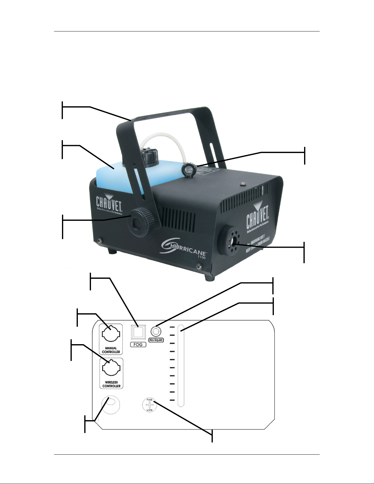
Fluid
container
Hanging
bracket
Low Flui d
indicator
Fluid lev el
Heater
Tilt
Wireless
Power input
(hardwired)
Fuse hold er
Manual
Manual Fog
button
Safety cable
eye bolt
2. INTRODUCTION
Product Overview
Adjustment
knob
Controller
Controller
Nozzle
indicator
Hurricane™ 1100 User Manual 5 Rev. 7
Page 6

258 mm / 10.2 in
242 mm / 9.5 in
225 mm / 8.9 in
Product Dimensions
Hurricane™ 1100 User Manual 6 Rev. 7
Page 7

The fuse is located
Unplug the IEC power cable before replacing the fuse! Always replace with
product has a replaceable fuse. In the event that the fuse needs to be replaced,
3. SETUP
AC Power
To d eterm ine the p ower r equirements f or a parti cular fixture, see the label affixed to t he
bac k plate of the fixture or r efer to the f ixt ure’s sp ecification s cha r t. A fixture’s li s ted
current rating is its average current draw under normal conditions. All fixtures must be
powered directly off a switched circuit and cannot be run off a rheostat (variable resistor)
or dimmer circuit, even if the rheostat or dimmer channel is used solely for a 0% to 100%
switch. Before applying power to a fixture, check that the source voltage m at ches the
fixture’s requirement. Check the fixture or device carefully to make sure that if a voltage
sel ection s w itc h ex ists that it i s set to the correct line voltage you wi ll use.
Fuse Replacement
same type of fuse.
This
follow the instructions provided below.
1. Using a flat hea d screwdriver, r emove the fuseholder from the IEC h ousing.
2. Remove the bad fuse from the fuseholder.
3. Insert the new fuse into the
fuseholder.
4. Install the fuseholder in the IEC
housing.
inside this
compartment.
Remove us i ng a flat
head screwdriver.
Hurricane™ 1100 User Manual 7 Rev. 7
Page 8

Hanging Clamp
Note!
Angled Down
Angled Up
Mounting
Orientation
Rigging
This fixture should only be mounted/used on a flat surface. Th is fi xture may not be tilted.
It is im portant n ever to ob struct th e vents’ pathways. Mou nt the fixture usi ng, a suitable “C”
or “O” type clamp.
• When selecting installation location, take into consideration the fluid
reservoir access and routine maintenance.
• Safety cables must alw ays b e used , utilizing the provided safet y eye bolt.
• Nev er mount in places where the fixture wi ll be exposed t o rain , high
humidi ty, extreme t emperatu re changes or restrict ed ventilati on.
Clamp is sold separately.
Hurricane™ 1100 User Manual 8 Rev. 7
Page 9

The INTERVAL is the time between bursts of fog.
Duration
Interval
Adjustment
Timer LED
Manual
LED
Manual/Power
LED
Manual control
Continuous
Timer Latching
Button
4. OPERATING INSTRUCTIONS
This mode will allow you to control the fogger manually, set the fog machine to run continuously, or
to set the fog machine to run off bursts with adjustable interval and durati on settings.
Manual Remote Operation (FC-M) (Standard)
1. Plug in the fog mac hine to power.
2. Plug in the M remote to the Manual Controller socket on the rear of the fog mac hine.
3. Press th e single button located o n the remote to t r igg er th e fog output.
The button is momentary, which means that the fog machine will only output while the
button is pressed. Once the button is released, the fog will stop outputting.
Timer Remote Operation (FC-T) (Optional)
1. Plug i n t he fo g m achine t o power.
2. Plug in the t imer rem ote t o t he Manual Controller socket on the rear of the fog m achi ne.
3. Press th e TIMER ON/OFF button on the timer r emote. The LED above the button should
light, indicating activation of function.
4. You may now set the INTERVAL & DURATION adjustment knobs to the desired position.
The DURATION is the time that the fog machine will run during the burst.
Adjustment
Indicator
Momentary
Momentary
Hurricane™ 1100 User Manual 9 Rev. 7
Latching Button
Page 10

Dipswitches
Wireless
LED indicator
LED indicator
Wireless
Wireless Controller (FC-W) (Optional)
This mode will all ow you to control the fogger using the optional wireless controller. This c onsists of
the transmitter and the receiver. You may control up to 4 independent fog machines, or many more
if you run them sim ultaneously. See the below instructions on setting up your fogger to operate with
the FC-W.
1. Plug the wi res r eceiver into t he fog mach ine 5-pin port labeled “Wireless Controller”.
2. There a re 4 b utt ons on t he wireless r emote t ran s mitter w hich act as tri ggers . Each button
can be assigned to a different fog machine. You may only choose 1 dipswitch on each
receiver. See th e belo w conf iguration for setti ng the receivers t o oper ate with the
transmitter remote.
Mode Dipswitches
CH1 1 = O n, 2-4 = Off
CH2 2 = On, 1,3,4 = Off
CH3 3 = On, 1,2,4 = Off
CH4 4 = On, 1,2,3 = Off
3. Press th e f og but ton, and t he fog machine will o utput fog m omentarily f or as l ong as you
hold down the butt on.
Transmitter
(ready)
(heating)
Receiver
Hurricane™ 1100 User Manual 10 Rev. 7
Page 11

No Power
Check mains power .
Chec k internal fuse.
No fog output
Check fluid level.
If using wireless, check dipswitches on receiver.
Breaker/Fuse keeps bl owing
Pos sible electr ical shor t. Contact Chauvet or a Chauvet
Dealer/distributor for further instruction.
Low fog output
Run a cleaning solution through the fog machine.
Check that the fog machine is plugged into the correct voltage.
Fog machine is not heating up
Chec k th e exter nal f use.
for further instruction.
Rem ote does not wor k
Make sure connector is firmly connected to device.
Chec k th e exter nal f use.
Fluid i ndicator states n o fog, but
Try resetting the fog machine by turning the power off, and then on
for further instruction.
General Troubleshooting
Symptom Solution(s)
Check external fuse.
Chec k remot e.
If using wireless, check batteries.
Chec k th e int ernal fuse.
Possible bad part. Contact Chauvet or a Chauvet Dealer/distributor
Try using another controller. Possible bad controller.
Chec k th e int ernal fuse.
the contain er if full .
If you still have a problem after trying the above solutions, please cont act CHAUVET Technical
Support at the location listed below.
again.
Possible bad part. Contact Chauvet or a Chauvet Dealer/distributor
Contact In for m a tio n
World Headquarters United Kingdom & Ireland
CHAUVET® CHAUVET® Europe Ltd.
General Informat ion
Address: 5200 NW 108th Avenue
Sunrise, FL 33351
Voice: (954) 577-4455
Fax: (954) 929-5560
Toll free: (800) 762-1084
Technical Support
Voice: (954) 577-4455 (Press 4)
Fax: (954) 756-8015
World Wide Web
www.chauvetlighting.com
General Informat ion
Address: Uni t 1C
Brookhill Road
Pinxton, Nottingham, UK
NG16 6NT
Voice: +44 (0)1773 511115
Fax: +44 (0)1773 511110
Email: uktech@chauvetlighting.com
World Wide Web
www.chauvetlighting.co.uk
Hurricane™ 1100 User Manual 11 Rev. 7
Page 12

5. TECHNICAL INFORMATION
Do not allow the haze m achine to become contaminated. After every 40 hours of
continuous operation, use Chauvet® Fog Cleaner Quart (or a solution of 80% distilled
General Maintenance
water and 20% distilled vinegar) through the syst em to prevent the accumulation of
particulate matter in the heating element is reco mmended.
The recommended cleaning regimen is as follows:
1. Empty all haze liquid from the machine.
2. Add cleaning solution to tank.
3. Plug unit in and allow it t o warm up.
4. Run the unit in a well-ventilated area until the tank is almost empty. Do not
allow the pump to run dry.
5. Cleaning is now complete. Refill with haze liquid. Run th e mac hine br iefly t o
clear any cleaning s olution from the pump and heater.
Fog Cleaner Quart (FCQ) was specifically developed by Chauvet® to clean your
Hurricane™ 1100. M ake sure you use FCQ regularly to increase the life of your
product.
Storage
Before storing this product, FCQ through the system as described in the cleaning
method above. This will help to avoid any particles condensing inside the pum p or
heater.
Test-run your Hurricane™ 1100 o n a monthly basi s to achieve th e best performanc e.
Hurricane™ 1100 User Manual 12 Rev. 7
Page 13

Return Procedure
Returned merchandise m ust be sent prepaid and in the original packing, call tags will not
be issued. Package must be clearly labeled with a Return Mer chandise Authorization
Number (RMA #). Products returned without a RMA # will be refused. Call CHAUVET and
request a RMA # prior to shipping the fixture. Be prepared to provide the model number,
serial numb er and a br ief desc r iption of the caus e for t he return . Be sure to prop er ly pack
fixture, any shipping damage resulting from inadequate packaging is the customer’s
responsibility. C HAUVET res erves th e r ight to use its own discretion to repair or replace
product(s). As a suggesti on, proper UPS packing or double-b ox ing is always a safe
met hod t o use.
If you are given an RMA #, please include the following information on a piece of
paper inside the box:
1. Your name
2. Your address
3. Your phone number
4. RMA #
5. A brief description of the sympt oms
Hurricane™ 1100 User Manual 13 Rev. 7
Page 14

TECHNICAL SPECIFICATIONS
WEIGHT & DIMENSIONS
Length ...................................................................................................10.2 in (258 mm)
Width ..................................................................................................... 9.5 in (242 mm)
Height .................................................................................................... 8.9 in (225 mm)
Weight ..................................................................................................... 8.4 lbs (3.8 kg)
POWER
AC Power....................................................................... 120 V 60 Hz AC or 230 V 50 Hz
Fuse (115V) .....................................................................................................8 A 250 V
Power Consumpti on ............................................................. 774 W (5.9 A) max at 120 V
Inrush Power ........................................................................................... (6.5A) at 120 V
Power Factor.............................................................................................. 0.99 at 120 V
Fuse (230V) .....................................................................................................5 A 250 V
Power Consumpti on ............................................................. 750 W (3.3 A) max at 230 V
Inrush Power .........................................................................................(3.14 A) at 230 V
Power Factor.............................................................................................. 0.99 at 230 V
THERMAL
Maximum ambient temperature .................................................................. 104°F (40°C)
CONTROL & PROGRAMMING
Data input ................................................................. 5-pin & ground DIN5 female socket
Data pin configur ationpin1(LED), pin2(control), pin3(+5V), pi n4( gr ound) , pin5(none), ground(none)
ORDERING INFORMATION
Hurricane™ 1100 .................................................................................................. F1100
Wired manual remote (included) FC-M
Wired timer remote ( optional) .................................................................................. FC-T
Wireless manual remote (optional) ......................................................................... FC-W
SPARE PARTS ORDERING INFORMATION
Master PCB .......................................................................................... P170-F1MSPCB
Heater P120-HT7
Pump ...................................................................................................... P200-F1PUMP
Fluid container ............................................................................................ P170-F1FLC
Fluid sensor P170-F1FLOS
Thermal switch .......................................................................................... P170-THEF11
Bracket knob ......................................................................................... P111-F1BKNOB
Fuse holder P170-FUSEHOL
Manual fog button .................................................................................... P111-F1FOGB
WARRANTY INFORMATION
Warranty ...................................................................................... 1-year limited warranty
Hurricane™ 1100 User Manual 14 Rev. 7
 Loading...