

Page 1
_fUipoiHgngpv
|
SERVICE
MANUAL
PA
1 1
2.
M
o
d
e
los
Page 2
TABLE
OF
CONTENTS
Introduction...
一
ーー
—
A.
Physical
B.
Principles
C.
Control
D.
Cross
E.
Design
IL
IL
IV.
Typical
A.
B.
Uneven
C.
D.
Trouble
.
Unit
Unit
.
Digital
n=>
D.
Controller
E.
No
F.
Low
G.
Uneven
Recommended
and
of
Principles
Section
Changes
Service
Loss
of
Fluidization
Fluidization
Loss
of
Temperature
Cellex
Spillage
Shooting
is
too
hot
will
not
readout
setting
Fluidization
Fluidization..
Fluidization
Engineering
Operation
Illustration
Reference
Problems
....
and
heat
is
.
...
of a Typical
Control
won't
cool
above
about
different
differs
from
or
Spouting
Tool
Kit
Principles
Table
from
....................
...........
dow:
1079
bed
temperature.
readout
Unit
.
AA
.
GUIA
a
ひひ
ひひ
NY
dv
00
00
00
90
VI.
|
VIL
VII.
Vill.
Heater
Replacing
Instructions
A.
B.
Controller
A.
B.
C.
D.
and
Blower
Motors
Step-by-step
Step-by-step
Design
Temperature
Air
Flow......
Bed
Temperature
Heater
.
The
.
Control & Measurement
.
Parts
.
Parts
.
Fluidotherapy
.
Circuit
MMUDEH>
.
Fluidotherapy
の
Shut
Overall
Placement
List/WEP 1 +
Diagram
and
for
Mounting
Instructions
Calibration
Criteria
Regulator
Down
System
Parts
Wiring
Specifications
Heaters
Measurement
.....
New
Controllers
Instructions
Circuit
.
System
Diagram
WEP 1 +
Controller
List.....
Diagram......
.
Controller
an
Diagram
Page 3
I.
INTRODUCTION
A.
Physical
Ina
Fluidotherapy
medium
air
vided
fluidization,
coming
other
particles
markedly
particles.
viscosity
are
This
the
sion
phase.
almost
variety
is
formed
through
particles.
microscopically
by
the
has
from
The
fluid,
generally
property
body
into
of
these
The
as
freely
of
resistive
and
Engineering
unit,
an
by
uniformly
the
bottom
is
established
rising
unusual
either
fluidized
exhibiting
attributable
permits
the
fluidized
parts
patient
as
of a bed
The
resulting
separated
gas.
This
properties
those
bed
characteristics
submergence
is
very
can
in
water
exercises.
Principles
air-fluidized
distributing
of
finely
state,
by
the
particles
from
"fluidized
which
of
the
gas
or
behaves
to a liquid
bed
much
exercise
and
like a low
state.
of
and
the
suspen-
like a liquid
in
the
can
perform
solid
di-
termed
be-
each
bed”
of
differ
of
the
which
parts
of
bath
a
B.
Principles
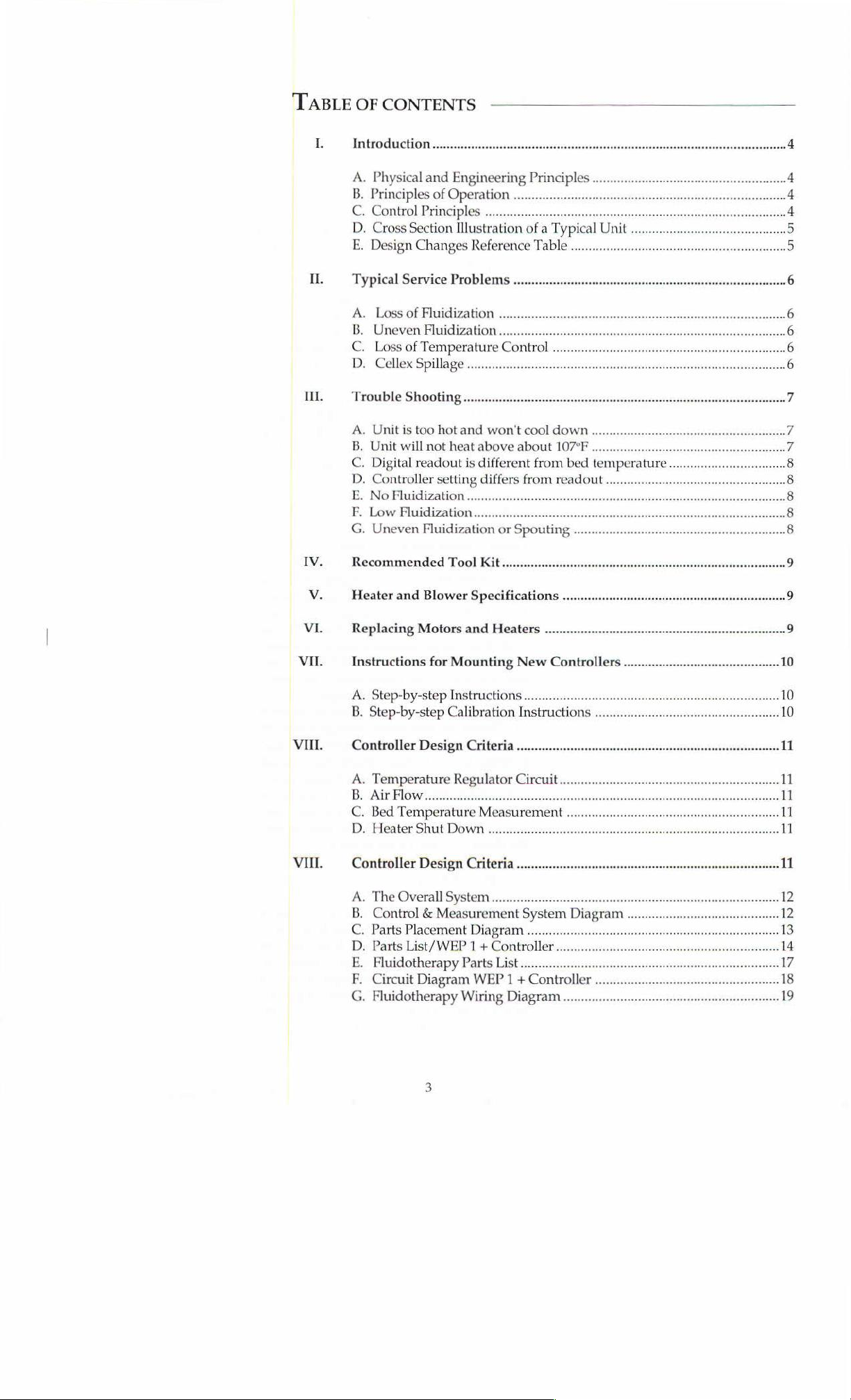
Figure 1
Fluidotherapy
(A)
contains
trol
the
of
the
heater
and
controlled
of
the
temperature
ture,
theothercontrolsit.
and
side
through
(B)
and
(D.
Heated
tributor
particles
wiched
and a
third
patient
sors.
Wooden
the
distributor
C.
Control
For
proper
the
airflow,
ment
chamber.
safety
provisions
In
particular,
temperature
heater
years,
have
various
been
of
Operation
illustrates
unit
the
electronic
speed
of
the
(C).
Bed
by
thermistors
sensors
entrances,
filter
(H)
then
over
heater
air
then
(J)
into
the
bed
(K).
The
between
from
being
two
plate
(L)
contacting
supports
and
Principles
operation,
and
the
In
mustbeincorporated
one
must
being
on
without
controllers
employed.
the
general
operation.
blower
temperature
(F)
respectively.
flows
(C)
into
flows
of
finely
foam
perforated
is
there
the
(M)
plates
it
is
temperature
additionto
guard
too
high,
principles
Control
circuits
(B)
and
(D)
measures
and
(G) are
through
plenum
through
divided
distributor
to
temperature
are
in
place.
necessary
basic
against
and
air
flow.
and
control
and
metal
used
of
panel
which
con-
the
output
is
sensed
(E).
One
tempera-
the
top
Air
enters
theblower
chamber
foam
dis-
Cellex*
is
sand-
plates,
prevent
in
against
the
sen-
to
hold
to
control
the
treat-
controls,
as
well.
the
bed
the
Over
the
schemes
4
Page 4
IH
Cross
sectional
view
fluidotherapy
Figure
of a typical
1
unit.
A
=
С
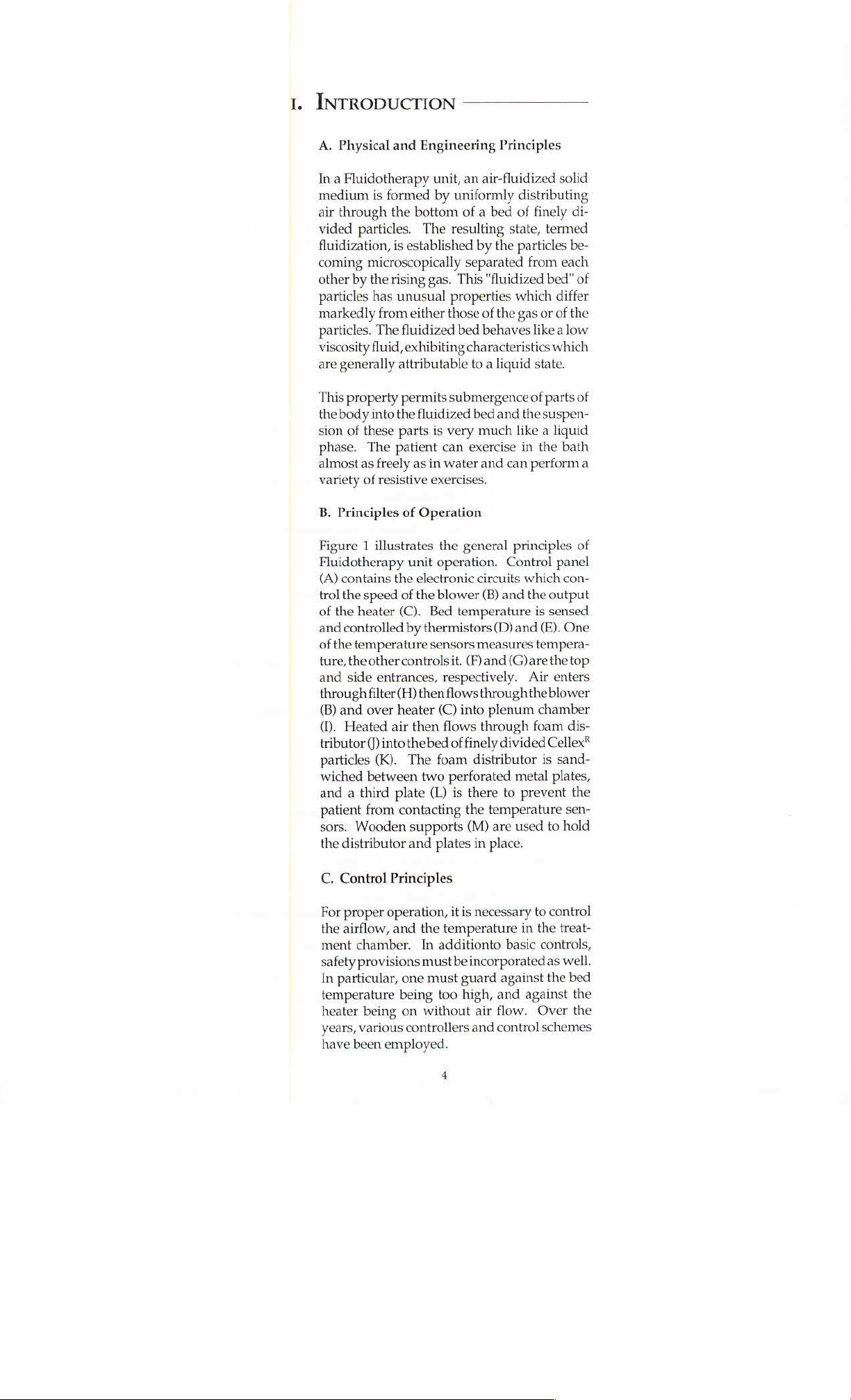
1973-1978
1978-1982
1982-1985
1985-
Motor
Control
Dayton
Low
Circuit
Low
Circuit
Low
Circuit
Model
Hysteresis
Hysteresis
Hysteresis
4X797
Triac
Triac
Triac
Heater
Control
(On-Off)
Duty-cycle
Duty-cycle
Duty-cycle
Fenwall
Modulated
Modulated
Modulated
Thermostat
Control
Control
Control
Timer
Dayton
Dayton
Electronic
(button
Electronic
(membrane
Model
Model
Module
control)
Module
2E270B
2E270B
switches)
Safety
features
Snap-Disc
Grainger 2 E634
Temperature-sensing
thermistor
if
bed
Low-current
on
which
low
Snap-Disc
located
Circuit
from
pletely
Snap-Disc
heater.
blower
completely
is
on.
cuts
under
is
above
motor
cuts
motor
at
to
being
off
Circuit
from
Pressure
off
power
blower
controller
prevent
Thermostat,
(in
bed)
cuts
off
heater
140ºF.
sensing
off
current.
Thermostat
heater.
turned
when
Thermostat
being
off
heater
blower
com-
heater
to
prevent
turned
when
sensor
if
pressure
falls
to
circuit
at
is
at
heater
which
ambient.
on.
Other
Changes
1973-1986
Until
1978,
solder
connectors
have been
connecti
ions
were
employed.
em]
loyed.
From
1978
to
1985,
spade
connectors were
used.
Since
1986,
modular
Page 5
|
|
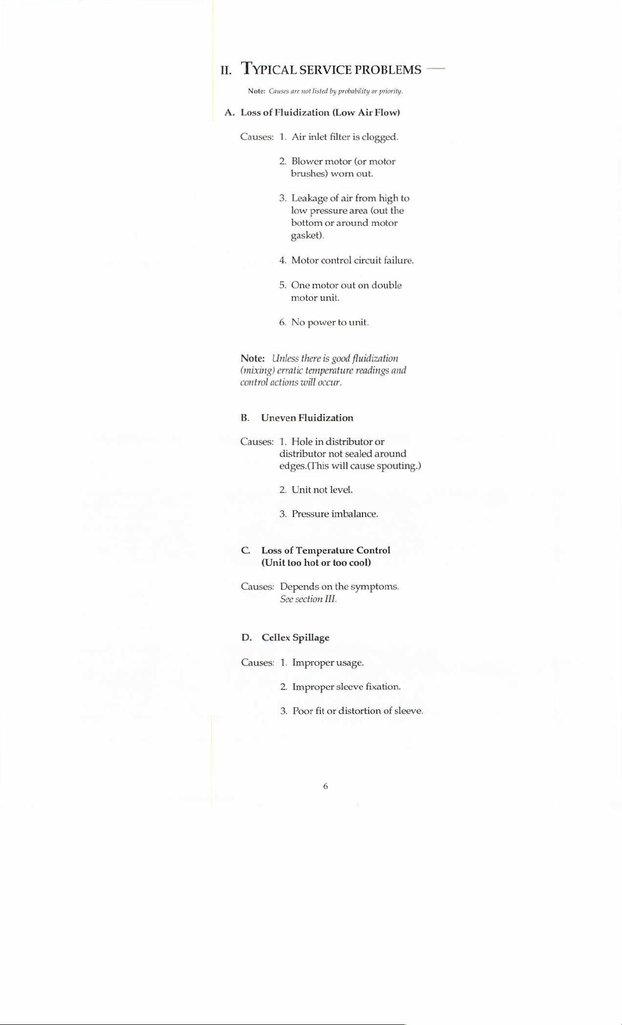
II.
A.
TYPICAL
Note:
Causes
Loss
of
Fluidization
SERVICE
are not
listed
PROBLEMS
by
probability
(Low
or
priority.
Air
Flow)
—
Causes:
Note:
(mixing)
control
B.
Unless
erratic
actions
Uneven
1.
Air
inlet
2.
Blower
brushes)
3.
Leakage
low
pressure
bottom
gasket).
4.
Motor
5.
One
motor
motor
6.
No
power
there
temperature
will
occur.
Fluidization
filter
motor
worn
of air
area
or
around
control
out
unit.
to
unit.
is
good
fluidization
is
clogged.
(or
motor
out.
from
high
(out
motor
circuit
failure.
on
double
readings
to
the
and
Causes:
C.
Loss
(Unit
Causes:
D.
Cellex
Causes:
1.
Hole
in
distributor
distributor
edges.(This
2.
Unit
3.
Pressure
of
Temperature
too
Depends
See
section
Spillage
1.
Improper
2.
Improper
3.
Poor
not
hot
fit
or
on
not
will
level.
imbalance.
III.
or
or
sealed
around
cause
Control
too
cool)
the
symptoms.
usage.
sleeve
fixation.
distortion
spouting.)
of
sleeve.
Page 6

ur.
TROUBLE
When
receiving a service
1.
If
the
LED
2.
That
there
caused
SA
How
(under
=
.
That
.
That
warmup).
Some
A.
by
long they
heavy
the
air
the
unit
typical
PROBLEM:
SHOOTING
display
is
poor
scenarios,
is
functioning
good
fluidization
fluidization).
have
had
use,
motor
filters
are
clean.
is
at
steady
and
Unit
is
-
call,
it
is
(because
the
unit,
brushes
state
(because
diagnoses
too
hot,
useful
(this
and
will
are:
and
won't
to
ascertain:
means
wear
the
poor
temperature
how
long
out
in
transients
cool
unit
has
since
about
can
occur
down
power).
control
the
last
one
can
service
year).
during
be
Condition:
Diagnosis:
Condition:
Possible
Condition:
Possible
Condition:
Possible
PROBLEM:
Diagnosis:
Diagnosis:
Diagnosis:
Lowest
There
this.
ture
Lowest
Lowest
temperature
is
nothing
Use
at
below
temperature
Inlet
Leak
Too
Motor
temperature
Wrong
Same
Heater
Temperature
Controller
Bad
temperature
LM324
IC
Unit
will
not
is
wrong.
lower
motor
105°F
is
required.
is
air
screen
(recycle)
hot
in
room
almost
above
temperature
as
110°F
light
burned
above
110°F,
out
temperature
sensor)
or
SC150D
#2
heat
above about
105°F
(with
Motor
setting
about
dirty
around
worn
heat
110°F
motor
out
120°F
reading
diagnoses
out
heater
of
calibration
sensor
Triacs
heater
alone
in
cooler
(with
(with
heater
light
won't
(verify
have
failed
107°F
off,
can
room,
heater
off,
go
by
switching
account
if
tempera-
off)
out
for
Condition:
Possible
Condition:
Possible
Heater
Diagnoses:
Heater
Diagnoses:
light
not
on
(Post
1985
failed
or
has
Temperature
Control
(Post
motor
light
Heater
Thermal
Fuse
Fuse
circuit
1982
failed
on
failure
snap-disc
failure
holder
Model)
been
disconnected.
sensor
calibration
Models)
broken
Pressure
failure
Low-current
sensor
incorrect
failure
safety
cutoff
switch
circuit
on
Page 7

PROBLEM:
Digital
bed
readout
temperature
temperature
is
different
from
Condition:
Possible
Diagnoses:
PROBLEM:
Condition:
Diagnoses:
PROBLEM:
Condition:
Possible
Condition:
Possible
Diagnoses:
Diagnoses:
Bed
temperature
Most
thermometers
SF,
also
depends
discrepancy
limb
immersion,
Controller
shows
Small,
Recalibration
No
fluidization--
Power
No
power
set
at,
different
or
large
temperature
required
to
motor
Motor
brushes
Poor
connection
to
motor
Motor
fuse
Motor
controller
was
measured
are
the
temperature
on
the
depth
is
more
than
and
recalibrate.
for
example
temperature
offsets
motor
off
worn
of
motor
failure
with
thermometer
only
accurate
measured
of
immersion.
5%,
verify
115°F,
but
wires
to 2-
If
the
by
readout
PROBLEM:
Condition:
Possible
PROBLEM:
Condition:
Possible
Diagnoses:
Diagnoses:
Low
fluidization
Motor
is
good
Air
Adjustable
high--See
Uneven
High motor
distribution
Distributor
Airflow
leak
in
speed
must
bottom
resistor
II.
A.
or
spouting
needs
be
adjusted-See
of
in
to
be
unit
or
motor
resealed
around
circuit
too
II.
В.
motor
Page 8

RECOMMENDED
Mm
Phillips
Very
Allen
ON
Digital
Adjustable
Wire
Fuses-15A,
Silicone
Thermometer
SONATA
10.
Knife
11.
Camper
12.
Motor
screw
small,
slottedscrew
wrench
multimeter
wrench
cutter,
crimper,
120V
and/or
tape,
brushes,
TOOL
driver
(.050"
size
(amps,
(or
stripper
scissors
masking
gasket,
KIT
driver
for
removing
volts,
wrench
tape
motor
(for
trim
ohms)
set)
pot
adjustments)
knobs
on
faceplate)
WARNING:
Unplug
service
Turning
insure
work.
your
the
unit
the
safety.
before
unit
off
any
will
VI.
not
HEATER
Heaters
'Finstrip'
Heater
'Finstrip'
Blower
Lamb
thru 2 inch
Blowers
Lamb
Three
REPLACING
Motors:
cabinet.
motors.
Connect
housing
mounting
gaskets
AND
for
Models
air
heaters,
for
Model
heater,
motor
for
#116309-00 1 stage,
orifice.
for
Model
#116312.00,
motors
required
To
access
Motors
Pull
motor
new
motor
and
install
hole
and
if
necessary.
BLOWER
110, 111, 113, 114, 210,
900
watts @ 120
211M.
1900
watts © 240
Models
SPECIFICATIONS
volts.
110,
111,
Flo-through,
211M.
roughly
MOTORS
the
are
motor
replace
115
for
Model
motor,
located
from
mounting
wires
into
in
motor
cubic
211M.
AND HEATERS
remove
behind
connectors.
mounting
bracket.
220.
volts.
113, 114, 115,
roughly
feet
per
the
screws
faceplate.
hole
and
hole.
Test
90
minute
Remove
unplug
Put
the
Make
motors
210,
attaching
220.
cubic
feet
thru a 2
faceplate
motor
connectors
gaskets
sure
motor
for
in
air
per
minute
inch
orifice.
bracket
on
place
is
centered
leaks
and
to
above
wires.
in
motor
adjust
in
Heater--Wood
cord
and
remove
screws.
bottom
Fiberglass
After
and
check
units
Units:
Toaccess
the
bottom.
mounting,
for
air
should
Heater
make
sure
leaks.
be
returned
the
heater,
is
heater
turn
located
does
to
factory
unit
in
metal
not
for
onits
air
touch
cabinet
heater
side
opposite
duct
secured
wall.
Replace
replacement.
power
by
two
Page 9

vu.
INSTRUCTIONS
STEP
STEP
STEP
STEP
The
calibration
STEP
STEP
1
2
3
4
new
controller
1
2
FOR
Unplug
Remove
abox,
Remove
Labeleachas
the
from
Reconnect
NOTE: A Polaroid
procedure
Place
access
no
Turn
clockwise).
(faceplate,
unit
screws
stool,
each
old
controller
faceplate.
each
is
now
follows:
controller
both
wires
can
blower
straight
MOUNTING
from
AC
from
faceplate,
or
small
table
of
the
wires
you
take
it
from
Replace
of
the
picture
can
also
hooked-up,
on a box,
the
controls,
short
circuit
control
Turn
knob
TEMPERATURE
up).
outlet.
under
and
cables
off.
You
the
unit.
with
new
cables
and
help
if
used
and
must
stool,
and
the
against
to
low
NEW
then
faceplate
should
CONTROLLER
remove
from
now
Remove
to
board,
original
controller.
wires
to
the
in
conjunction
or
small
circuit
the
position
with
be
calibrated.
table
board.
p.c.
board.
(faceplate,
CONTROL
faceplate.
rest
controller
one
at a time.
beable
to
controller
new
controller.
wire
labels
The
so
that
Be
sure
knob
一
Place
on.
remove
you
can
that
counter-
to
115°
STEP
STEP
STEP
STEP
3
4
5
6
Place
thermometer
Plug
in
the
unit.
up
to
give
good
ning.
Allow
the
unit
thermometer.
lightis
flashing
is
on
when
the
Allow
the
unit
temperature
115°,
slightly
adjust
longer
for
at
with
adjust
trim
shorter
trim
pot
duration.
least
ten
into
the
treatment
Push
treatment
fluidization.
torun
until
it
reaches
Adjust
to
trim
on
and
off
light
is
on.
run
forabout
the
thermometer.
pot
R20
duration;
R20
so
that
Repeat
STEP
pot
(about
so
if
the
minutes.
bed
button.
Unit
should
115°,
R20
on
p.c.
50%
on,
10
minutes
If
the
that
the
heater
the
temperature
heater
6,
until
light
the
of
the
unit.
Turn
blower
now
be
on
as
measured
board
until
the
50%
off).
The
more,
then
check
temperature
light
is
is
below
is
on
for a slightly
unit
remains
control
and
run-
with
the
heater
heater
bed
is
above
on
for
115°,
at
115°
a
10
Page 10

Atthis
mains
The
degrees.
STEP
STEP
STEP
VIII.
point,
the
temperature
is
to
calibrate
unit
should
The
1
2
3
still
procedure
Adjust
(on
measured
Putsome
vibration
Reattach
CONTROLLERDESIGNCRITERIA
A.
Temperature
B.
Air
flow:
Thisis
volume
flow,
controller
the
digital
be
running,
follows:
trim
pot
Controller)
control
shows
with
the
nail
polish,
from
slowly
faceplate
over
controllable
to
the
maximum
has
temperature
and
the
on
Module A (see
'115'.
thermometer.
or
glyptol
turning
to
cabinet.
the
range:
over
the
required
been
calibrated,
readout.
bed
temperature
Figure
3)
until
This
should
on
the
the
一
trim
trim
一
be
the
pots
pots.
一
105°F < T < 130°F.
range
from
minimal
for
violent
bed
and
all
thatre-
should
一
be 115
the
readout
temperature
to
prevent
一
fluidization
activity.
the
一
C. © Bedtemperature
digitally
D.
Heatershut-down:
fluidization.
displays
measurement:
bed
temperature
The
heaters
The
measuring
over
are
disabled
the
system
range
in
case
measuresand
from
100°F
of
insufficient
to
130°F.
bed
11
Page 11

THE
OVERALL
SYSTEM
Figure 2 shows
final
system.
‘a
separate
is a phase-controlled
to
the
motor,
The
heater
control
maintains
heaters
cycle,
The
switch,
(event
The
temperature
temperature
with
put
The
controls
found
duty
less
continuous
the
switches.
on
with a fixed
other
shutting
of
inadeguate
circuitry
an
associated
controls a pulse
output
the
that
cycle,
than
duty
cycle
the
block
The
motor
block
of
the
control
temperature
and
part
controller
of
heater
the
operating
ten
heat
circuit
One
off
with a variable
time
of
the
circuit
down
bed
which
dependent
amplifier,
the
pulse
switch.
heaters,
in
seconds,
output
of
the
control
AC
acts
diagram
control
system.
voltage
control
by
the
air
is
current
width
width
with
recycle
have a smooth,
proportional
circuit
Its
output
applied
has a pair
switch
switching
recycle
as a feedback
composed
period.
acts
asa
safety
heaters
in
flow.
source,
whose
modulator.
modulator
It
has
controlled
periods
signal.
of
the
of
the
duty
the
of
out-
been
of
to
is
a
The Control
Measurement
Figure
and
System
2
|
HEATER
+
SENSOR
REFERENCE]
BED
T
SENSOR
da
=
DI
CONTROL
HEATER
INHIBIT
———>
ICOMPARATORI
HEATER
SWITCH
|
Wolor
HEATER
PULSE
WID'
=
MODULATOR
=
PRESSURE
SWITCH
Page 12

e
19
00094
a
1a
=
1760.24
901
van
Cie
|
α[ρος»]
END
94 SH
Ù
[0
l
iq
コー
F
ή
g”
18
1 ‘
nen
.
az,
|
PHA
018
64
tal
Lee)
vnnaow
eo
+
Hu
Tu
y
ae
“Sam
sui
gu
E
SNole
)
za
eu
au
|
eo
L
se
|
S
ΒΝΟ
ΗΟΕΟΟΝ
E
019
|
019
IR
H
Go
özi
>
|
tra
[E]
ni
elo
Be
Figure
Parts
3
Placement
Diagram
13
*
CN3
is
located
on
Module A in
latest
style
PCB.
Page 13

CONTROLLER
CIRCUITRY
eragy
DATE:
2
01702792
pe
T
15:07:
oroe57664。
«ο
[SHEET
€
03
Re
OF
os
WEP=1+
SCHEMATIC
Figure
Circuit
4
Diagram
WEP1+
Controller
18
Shea ovat
2)
er
Page 14

JosussoujJsu」
[|
lojluoo
JaleaH
]
=.
Josuasouay
oe
|
Aejdsiq
I
UOIAS
9JnSS9Jd
(siluAW)
laJineN
Е
0102
1900
生
|IGJIu590
F
İM
JoJo
EN)
JeleaH
3503
7
이
이
0503
1816
하 1
seigld
uoHndu1SIQ
Figure
Fluidotherapy
5
Wiring
Diagram
19
 Loading...