

Page 1
ISO 13485 CERTIFIED
SERVICE MANUAL
Models:
1480
(Serial Numbers- 1000 and above)
1481
(Serial Numbers- 1000 and above)
Page 2

Fluido DHT™Dry Heat Therapy Unit
TABLE OF CONTENTS
©2003 Encore Medical Corporation or its affiliates, Austin, Texas, USA. Any use of editorial, pictorial or layout composition of this publication without express written consent from
Chattanooga Group of Encore Medical, L.P. is strictly prohibited. This publication was written, illustrated and prepared for print by Chattanooga Group of Encore Medical, L.P.
Foreword . . . . . . . . . . . . . . . . . . . . . . . . . . . . . . . . . .1
Precautionary Symbol Definitions . . . . . . . . . . . .2
Safety Precautions . . . . . . . . . . . . . . . . . . . . . . . .3-4
Theory of Operation . . . . . . . . . . . . . . . . . . . . . . . . .5
Nomenclature . . . . . . . . . . . . . . . . . . . . . . . . . . . .6-7
Specifications . . . . . . . . . . . . . . . . . . . . . . . . . . . . . .8
Troubleshooting . . . . . . . . . . . . . . . . . . . . . . . . .9-12
Fluido Software Error Messages . . . . . . . . . . . .9
Motor/Blower Error . . . . . . . . . . . . . . . . . . . . . . .9
Temperature Sensor Error . . . . . . . . . . . . . . . . . .9
Fluido System Testing . . . . . . . . . . . . . . . . . .10-12
Visual Inspection . . . . . . . . . . . . . . . . . . . . .11
Ground Resistance Test . . . . . . . . . . . . . . .11
Leakage Tests . . . . . . . . . . . . . . . . . . . . . . . .11
Resetting Fluido Factory Defaults . . . . . . .11
Preheat Test . . . . . . . . . . . . . . . . . . . . . . . . .11
Pulse Mode Test . . . . . . . . . . . . . . . . . . . . . .12
Treatment Time Test . . . . . . . . . . . . . . . . . . .12
Air Speed Test . . . . . . . . . . . . . . . . . . . . . . . .12
Control Panel Lock-Up . . . . . . . . . . . . . . . . .12
Removal & Replacement Procedures . . . . . .13-20
Sleeves and Cellex . . . . . . . . . . . . . . . . . . . . . . .13
Control Panel PC Board . . . . . . . . . . . . . . . .13-14
Fluido Heater . . . . . . . . . . . . . . . . . . . . . . . . .15-18
Fluido Diffuser . . . . . . . . . . . . . . . . . . . . . . . . . . .18
Fluido Motor . . . . . . . . . . . . . . . . . . . . . . . . . .18-19
Muffler and Muffler Cover . . . . . . . . . . . . . . . . .19
Casters . . . . . . . . . . . . . . . . . . . . . . . . . . . . . . . . .20
Replacement Parts . . . . . . . . . . . . . . . . . . . . . .21-22
Diagrams . . . . . . . . . . . . . . . . . . . . . . . . . . . . . .23-45
Base Assembly - 120v and 230v . . . . . . . . . . . .23
Control Panel Assembly - 120v and 230 v . . . .24
Lid Assembly - 120v and 230v . . . . . . . . . . . . . .25
Switch Plate Assembly - 120v . . . . . . . . . . . . . .26
Switch Plate Assembly - 230v . . . . . . . . . . . . . .27
Wiring Diagram - 120v . . . . . . . . . . . . . . . . . . . .28
Wiring Diagram - 230v . . . . . . . . . . . . . . . . . . . .29
Heater Enclosure Assembly - 120v . . . . . . . . .30
Heater Enclosure Assembly - 230v . . . . . . . . .31
Motor & Support Assembly - 120v . . . . . . . . . .32
Motor & Support Assembly - 230v . . . . . . . . . .33
Motor Housing Assembly (1) - 120v . . . . . . . . .34
Motor Housing Assembly (1) - 230v . . . . . . . . .35
Motor Housing Assembly (2) - 120v . . . . . . . . .36
Motor Housing Assembly (2) - 230v . . . . . . . . .37
Motor Housing Assembly (3) - 120v . . . . . . . . .38
Motor Housing Assembly (3) - 230v . . . . . . . . .39
Final Assembly (1) - 120v . . . . . . . . . . . . . . . . . .40
Final Assembly (1) - 230v . . . . . . . . . . . . . . . . . .41
Final Assembly (2) - 120v . . . . . . . . . . . . . . . . . .42
Final Assembly (2) - 230v . . . . . . . . . . . . . . . . . .43
Final Assembly (3) - 120v . . . . . . . . . . . . . . . . . .44
Final Assembly (3) - 230v . . . . . . . . . . . . . . . . . .45
Warranty . . . . . . . . . . . . . . . . . . . . . . . . . . . . . . . . . .46
Warranty Repair/Out of Warranty Repair
. . . . . .46
Page 3

Fluido DHT™Dry Heat Therapy Unit
FOREWORD
1
Read, understand and follow the Safety Precautions and information contained in this manual.
This manual contains the necessary safety, and field service information for those Field Service Technicians, approved by
Chattanooga Group, to perform field service on the Fluido DHT Models 1480 and 1481 units.
At the time of publication, the information contained herein was current and up to date. However, due to continual
technological improvements and increased clinical knowledge in the field of fluidotherapy, as well as Chattanooga Group’s
policy of continual improvement, Chattanooga Group reserves the right to make periodic changes and improvements to their
equipment and documentation without any obligation on the part of Chattanooga Group.
It is the sole responsibility for field technicians to stay informed and trained in the latest technology utilized in the Fluido DHT
Models 1480 and 1481 units by Chattanooga Group. From time to time, as significant improvements are incorporated, Service
Bulletins will be produced and made available on our web site (www.chattgroup.com) in lieu of reprinting a complete manual
prematurely. These Service Bulletins will provide updated service information and technological improvements to the Fluido
DHT Models 1480 and 1481 for use by approved service technicians.
“Approved Service Technician” Definitions;
1. Level I- Those Field Service Technicians that have successfully completed the minimal training required by Chattanooga
Group, in basic service techniques.
2. Level II- Those Field Service Technicians that have successfully completed Level I Training as well as Level II Training as
required to perform specific troubleshooting and repair techniques and procedures.
3. Level III- Those Field Service Technicians that have successfully completed Levels I & II Training as well as Level III
Advanced Training as required to perform all necessary Troubleshooting and Repair techniques. The Technician
having successfully completed the three levels of training and coupled with experience should have the ability to
train other technicians in Level I and Level II Training with the necessary Training Materials from Chattanooga
Group.
4. Temporary- Chattanooga Group, at its discretion and based on known experience of the technician, may grant a
“Temporary Approval” to a field technician for particular troubleshooting and repair of a specific unit requiring
immediate attention. This “Temporary Approval” in no fashion acknowledges the training level of a technician
as defined above. This “Temporary Approval” is utilized only in unique situations for a specific unit for a
specific service technique only and is documented as such.
Due to the complex nature of the technology utilized by Chattanooga Group, the recommended troubleshooting techniques for
PC Boards are to determine “Bad Board” and PC Board replacement only. No board component level troubleshooting is
recommended nor will information or parts be supplied by Chattanooga Group. Any PC Board component level troubleshooting
performed will be at sole risk and liability of the Service Technician performing such troubleshooting techniques.
This equipment is to be sold and used only under the prescription and supervision of a licensed medical practitioner.
This equipment is to be serviced only by an “Approved Service Technician”.
For Additional Service Contact:
Chattanooga Group
DHT Support Department
Toll Free: 1-866-864-0598
Outside USA: +1-423-870-7200
Page 4
Fluido DHT™Dry Heat Therapy Unit
SYMBOL DEFINITION
2
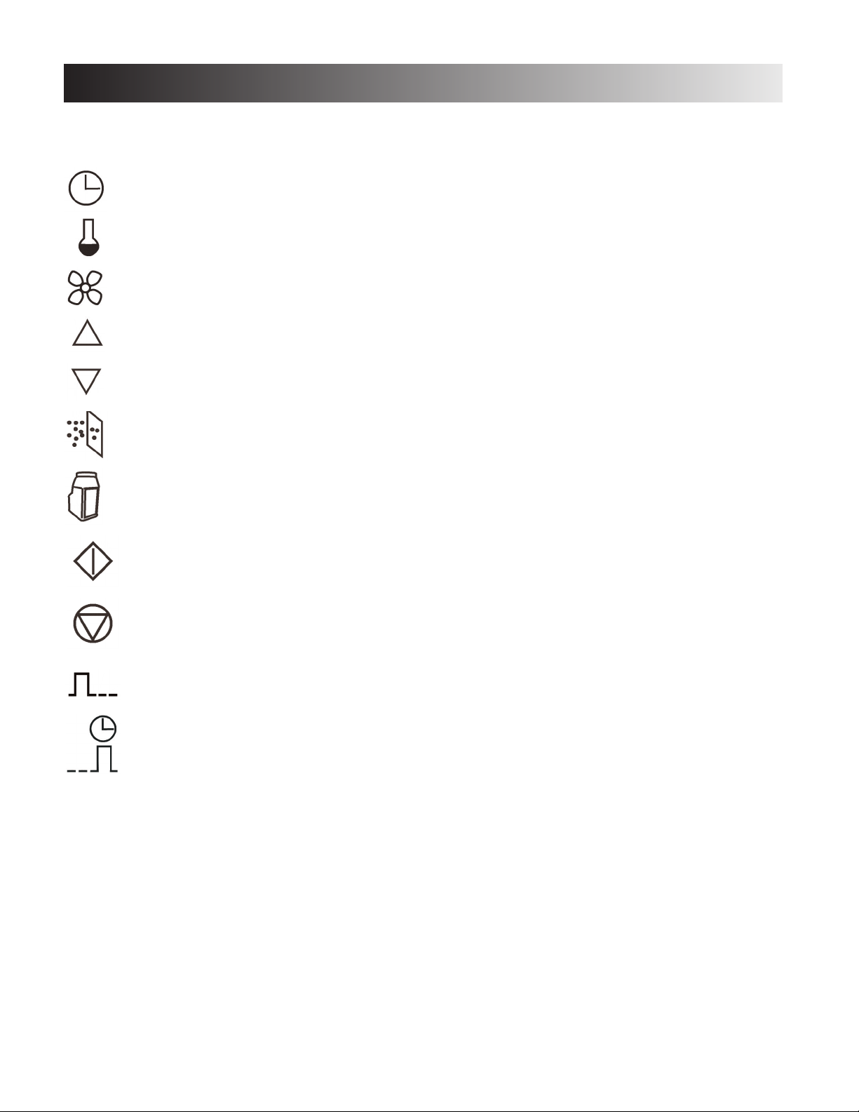
The following symbols are located on the Chattanooga Group Fluido DHT Dry Heat Therapy Unit Control Panel. Understand the
meaning of each symbol before attempting any operation or use of the unit.
This symbol indicates therapy session Time
adjustment.
This symbol indicates therapy session Temperature
adjustment.
This symbol indicates therapy session Air Speed
adjustment.
This symbol indicates Upward adjustment in
function parameters.
This symbol indicates Downward adjustment in
function parameters.
This symbol with the illuminated Blue indicator light
indicates the Intake Filter requires changing.
This symbol indicates Start therapy session.
This symbol indicates Stop therapy session.
This symbol indicates Pulse Mode for pulse
therapy sessions.
This symbol indicates Preheat Standby function.
This symbol with the illuminated Blue indicator light
indicates the Cellex®media requires changing.
Page 5
Fluido DHT™Dry Heat Therapy Unit
3
SAFETY PRECAUTIONS
Precautionary Symbol Definitions
The precautionary instructions found throughout this
manual are indicated by specific symbols.
Understand these symbols and their definitions before
operating or servicing this equipment. The definitions of
these symbols are as follows:
CAUTION
Text with a “CAUTION” indicator will explain possible
safety infractions that could have the potential to
cause minor to moderate injury or damage to
equipment.
WARNING
Text with a “WARNING” indicator will explain possible
safety infractions that will potentially cause serious
injury and equipment damage.
DANGER
Text with a “DANGER” indicator will explain possible
safety infractions that are imminently hazardous
situations that would result in death or serious injury.
EXPLOSION HAZARD
Do not use this equipment in the presence of
flammable anesthetics. This symbol is also
prominently displayed on the serial number plate of
the unit.
NOTE:
Throughout this manual “NOTE” may be found.
The Notes are helpful information to aid in the
particular area or function being described.
Safety Precautions
Read, understand and follow all safety precautions
found in this manual. The following are general safety
precautions that must be read and understood before
attempting any service techniques on these units.
Throughout this manual, specific safety precautions will
be found. Read, understand and follow all safety
precautions.
!
CAUTION
WARNING
!
!
DANGER
• Read, understand and practice the precautionary and operating
instructions found in this manual. Know the limitations and
hazards associated with using any electrical device. Observe the
precautionary and operational decals placed on the unit.
• DO NOT operate the unit when connected to any unit other than
Chattanooga Group devices.
• Refill unit daily to proper fill level with Chattanooga Group Cellex®Dry
Heat Medium.
• Change Cellex Dry Heat Medium every six (6) months.
• Use only Cellex Dry Heat Medium in the Fluidotherapy units.
• Clean Inlet Filter(s) daily before unit startup.
• Use only fingers to operate button controls on the control panel(s).
Use of sharp objects such as pencils or pens will result in damage to
the unit.
• Turn unit to the “Standby” mode before positioning a patient or
removing a patient from the unit.
• After or between treatments, do not immediately unplug or turn the
power off from the unit. Allow the unit to process through the “Cool
Down” cycle. The unit cycles into standby mode after treatment time
has elapsed. Standby can be disabled by pressing the
preheat/standby button. The unit goes to a 3 minute cool down mode
after standby is turned off. Turning the power off before cool down
completes is potentially hazardous to the equipment, and could lead
to failure of the unit. It is recommended that power be supplied to the
unit at all times. Keep in mind that the recommended treatment air
speed is 50%
• Secure all entry ports before turning the unit ON.
• Check unit temperature before treating patient to ensure correct
temperature.
• Place the patient in a comfortable position allowing for correct
placement of the limb being treated.
• Proper storage and transport temperatures for the Fluido DHT
units are 40°F - 158°F (4.5 °C - 70°C). Relative Humidity 85%.
• This equipment generates, uses and can radiate radio frequency
energy and, if not installed and used in accordance with the
instructions, may cause harmful interference to other devices in
the vicinity. However, there is no guarantee that interference will
not occur in a particular installation. Harmful interference to other
devices can be determined by turning this equipment on and off.
Try to correct the interference using one or more of the following:
Reorient or relocate the receiving device, increase the separation
between the equipment, connect the equipment to an outlet on a
different circuit from that to which the other device(s) are connected
and/or consult the factory field service technician for help.
!
CAUTION
Page 6

Fluido DHT™Dry Heat Therapy Unit
4
SAFETY PRECAUTIONS
Safety Precautions Continued
• Federal law restricts this device to sale by, or on the
order of, a physician or licensed practitioner. This
device should be used only under the continued
supervision of a physician or licensed practitioner.
• For continued protection against fire hazard, replace
fuses only with ones of the correct type and rating.
•
Make certain the unit is electrically grounded by
connecting
only to a grounded electrical service
receptacle conforming to
the applicable national and
local electrical codes.
• This device should be kept away from children.
• Care must be taken when operating this equipment
around other equipment. Potential electromagnetic or
other interference could occur to this or to the other
equipment. Try to minimize this interference by not
using other equipment in conjunction with it.
•
Before administering any treatment to a patient you
should become acquainted
with the operating
procedures for each mode of treatment available, as
well as the indications, contraindications, warnings and
precautions. Consult other
resources for additional
information regarding the application of Dry Heat
Therapy.
• To prevent electrical shock, disconnect the unit from
the power source before attempting any maintenance
procedures.
• Use only Cellex
®
processed dry heat medium in the unit
to prevent excessive dusting.
• Adequate precautions should be taken when
treating individuals with suspected or diagnosed
medical conditions or diseases such as heart
problems, epilepsy, diabetes, etc.
• Prior to treatment, consult a medical professional
familiar with the precautionary measures to be
taken for patients that may experience allergic
reactions to dust and pollen.
• Properly dispose of used Cellex according to National
and local laws, rules and regulations.
WARNING
!
• Explosion hazard if used in the presence of
flammable anesthetics. The warning symbol for
this hazard is prominently displayed on the serial
number plate.
• Perform all Required Maintenance as described in this
and the User Manual. Strict adherence to the Required
Maintenance for the Fluido DHT units is mandatory. Failure
to perform the Required Maintenance could result in the
Cellex medium entering the heat chamber of the unit(s)
and cause severe injury to patients as well as smoke
damage to the facility and the Fluido DHT unit(s).
• Make certain the unit is unplugged from the power source
before attempting any removal and replacement procedures
on the unit.
DANGER
Page 7
Fluido DHT™Dry Heat Therapy Unit
5
THEORY of OPERATION
The Fluido DHT utilizes ambient air and pressurizes it via an internal blower. The pressurized air is directed across a heating
element bringing the air to the desired treatment temperature. The heated, pressurized air is then diffused across and through
a baffle to fluidize and heat the Cellex media in a patient treatment reservoir. All treatment parameters; air speed, temperature,
treatment time and the unit preheat settings are programmed by the operator with the touch panel user interface. The Fluido
DHT unit base incorporates four locking casters and a manually operated hydraulic lift to adjust height and rotation of the
treatment reservoir for patient comfort.
Page 8
Fluido DHT™Dry Heat Therapy Unit
6
NOMENCLATURE
Fluido DHT
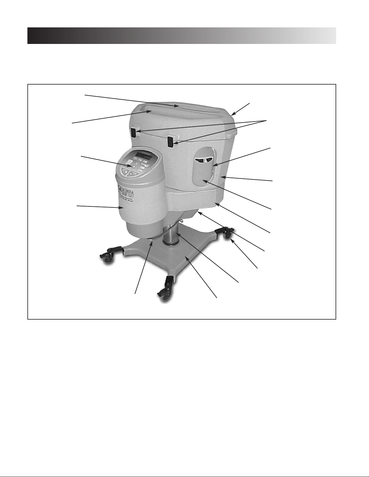
The nomenclature graphics below, Figure 3.1, indicate the
general locations of the major components of the Fluido
DHT unit.
Know the components and their functions before performing
any operation of or service to the Fluido DHT Model 1480
and 1481 unit.
11
22
33
44
55
66
99
1100
1111
88
77
1122
1133
1144
1155
1. RESERVOIR LID - Allows access to the treatment
cavity for adding Cellex
®
medium.
2. LATCHES - Secures Reservoir Lid
3. SIDE ACCESS PORTS - Four available Side Access
Ports. Two on each end of the unit.
4. RESERVOIR/TREATMENT CAVITY - Patient treatment
cavity and Cellex Reservoir.
5. TREATMENT LIMB SLEEVES - Replaceable and
launderable patient limb treatment sleeves.
6. HEAT CHAMBER - Houses Heating element.
7. INTAKE FILTER - Air intake filter. Requires periodic
replacement.
8. LOCKING CASTERS - Four Locking Casters for
securing the unit in place for treatment.
9. ELEVATION ADJUSTMENT CYLINDER - Adjusts and
maintains reservoir to desired height for patient comfort.
10. UNIT BASE - Rigid unit base for ease in transporting
unit to different locations for treatment.
11. HEIGHT ADJUSTMENT PEDAL - Used to raise, rotate,
release and lock the cylinder for height adjustment of
the unit.
12. BLOWER HOUSING - Houses Blower Motor.
13. CONTROL PANEL - Operator Controls. See Page 7 for
detail description of each control.
14. TREATMENT CAVITY VIEWING WINDOW - View
treatment area during treatment.
15. TOP ACCESS PORT - Top Treatment access port with
sleeve.
Page 9
Fluido DHT™Dry Heat Therapy Unit
7
NOMENCLATURE
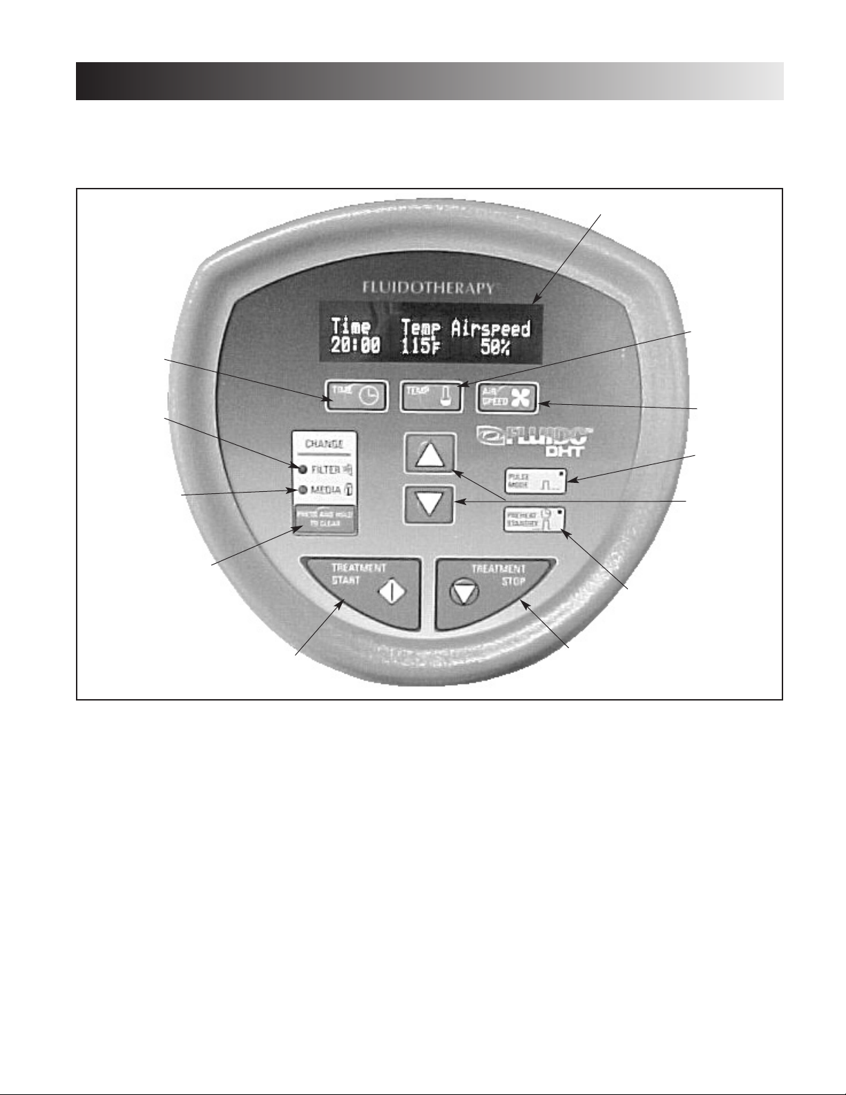
Fluido Control Panel
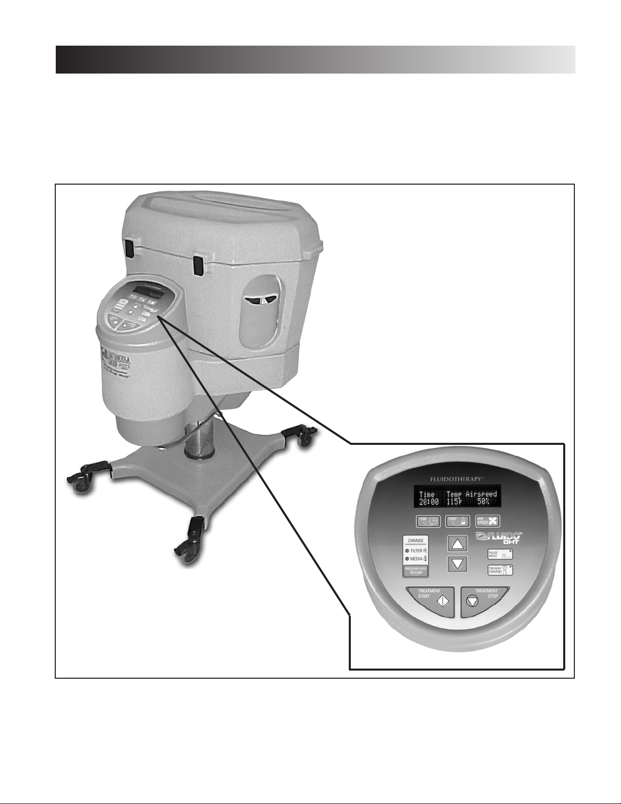
The Control Panel nomenclature graphics below, Figure
3.2, indicate the location and functions of the Fluido DHT
Model 1480 and 1481 control panel.
Know the components and their functions before performing
any operation of or service to the Fluido DHT Model 1480
and 1481 unit.
11
22
33
44
55
66
77
88
99
1100
1111
1122
1. PANEL DISPLAY- Displays settings and operational
parameters.
2. TEMPERATURE- Use in conjunction with the Up and
Down arrows to set operation Temperature.
Temperature can be adjusted in 1° increments. The
available temperature range is 88° F to 130° F
(31° C to 54° C).
3. AIR SPEED- Use in conjunction with the Up and Down
arrows to adjust air speed for fluidization of the Cellex
®
Medium. Available speeds range from 5% to 100% (in
5% increments).
4. PULSE MODE- Turn Pulse Mode On and Off as well as
adjust pulse time. Available Pulse Time is from 1
second On/1 Second Off to 6 Seconds On/6 Seconds
Off.
5. UP and DOWN ARROWS- Use in conjunction with
other mode or function buttons to set desired
parameters.
6. PREHEAT STANDBY- Turn the Preheat Standby Mode
On and Off as well as set the parameters desired for
the Preheat Standby Mode to automatically start.
7. TREATMENT STOP- Press to stop treatment.
8. TREATMENT START- Press to start treatment.
9. CLEAR BUTTON- Used to turn off maintenance
indicators after maintenance has been properly
performed.
10. MEDIA- Indicator will light when it is time to change the
Cellex
®
Medium.
11. FILTER- Indicator will light when it is time to change the
required filters.
12. TIME- Use in conjunction with the Up and Down arrow
buttons to set treatment time. Available time is 1 to 99
minutes, in one minute increments, or Continuous.
Page 10
Fluido DHT™Dry Heat Therapy Unit
8
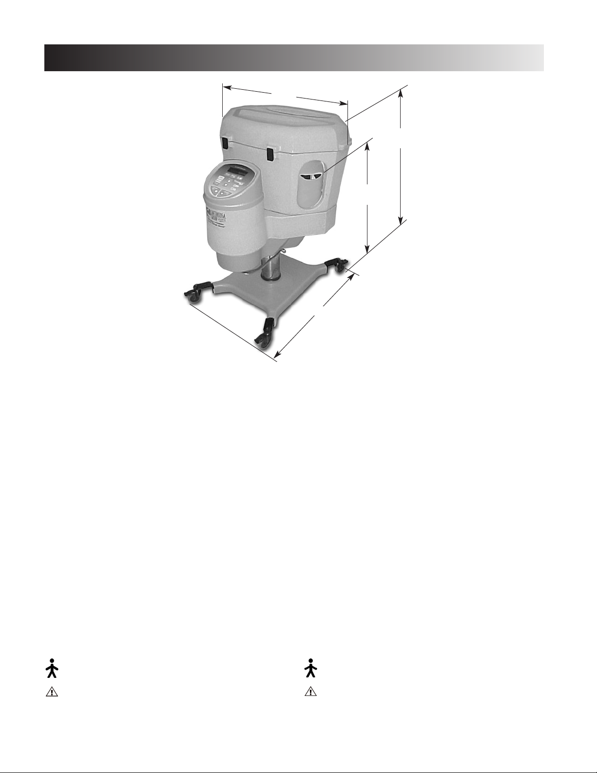
SPECIFICATIONS
DDeepptthh
OOvveerraallll
HHeeiigghhtt
WWiiddtthh
PPaattiieenntt
HHeeiigghhtt
MMOODDEE OOFF OOPPEERRAATTIIOONN
. . . . . . . . . . . . . . . . . . . . . . Continuous
OOPPEERRAATTIIOONNAALL FFUUNNCCTTIIOONNSS
VVaarriiaabbllee AAddjjuussttmmeennttss
. . . . . . . . Time, Temp and Air Speed
PPuullssee MMooddee
. . . . . . . . . . . . . . . . . . . . OFF to 6 Sec ON/OFF
AAvvaaiillaabbllee LLaanngguuaaggeess
. . . . . . . . English, Spanish and French
TTRREEAATTMMEENNTT TTIIMMEE
. . . . . . . . 1 to 99 minutes and Continuous
**OOPPEERRAATTIINNGG TTEEMMPPEERRAATTUURREE
. 88 °F (31 °C) to 130 °F (54 °C)
AAIIRR SSPPEEEEDD
. . . . . . . . . . . . . . . . 5% to 100% (5% increments)
PPRREEHHEEAATT TTIIMMEERR
. . . . . Per default setting with 50% Air Flow
during 30 min. preheat then 5%
airflow for standby.
CCeelllleexx
®®
MMEEDDIIUUMM CCAAPPAACCIITTYY
. . . . . . . . . . . 20-25 lbs (9-11 kg)
IINNPPUUTT PPOOWWEERR
. . . . . . . . . . . . . . . . . . . . . 120V, 50/60 Hz, 12A
FFUUSSEE RRAATTIINNGG
. . . . . . . . . . . . . . . . 10 A Time Delay (Slo-Blow)
PPHHYYSSIICCAALL DDIIMMEENNSSIIOONNSS
UUnniitt DDeepptthh
. . . . . . . . . . . . . . . . . . . . . . . . . . . . . 31” (79 cm)
UUnniitt WWiiddtthh
. . . . . . . . . . . . . . . . . . . . . . . . . . . . 29.5” (75 cm)
OOvveerraallll HHeeiigghhtt
. . . . . . . . . . . . . 41” - 49” (104 cm - 124 cm)
PPaattiieenntt HHeeiigghhtt
. . . . . . . . . . . . . . . 31” - 39” (79 cm - 99 cm)
RReesseerrvvooiirr SSwwiivveell
. . . . . . . . . . . . . . . . . . . . . . . . . . . . . . 360°
WWeeiigghhtt
. . . . . . . . . . . . . . . . . . . . . . . . . . . . . 145 lbs (66 kg)
SShhiippppiinngg WWeeiigghhtt
(Including Stool) . . . . . . . . 210 lbs (95 kg)
EElleeccttrriiccaall::
Class I
TTyyppee BB EEqquuiippmmeenntt
AAtttteennttiioonn,, ccoonnssuulltt aaccccoommppaannyyiinngg ddooccuummeennttaattiioonn..
OOrrddiinnaarryy eeqquuiippmmeenntt:: NNoott ddeessiiggnneedd ttoo pprreevveenntt iinnggrreessss ooff
wwaatteerr..
*Dependent upon airspeed selected
Model 1480
MMOODDEE OOFF OOPPEERRAATTIIOONN
. . . . . . . . . . . . . . . . . . . . . . Continuous
OOPPEERRAATTIIOONNAALL FFUUNNCCTTIIOONNSS
VVaarriiaabbllee AAddjjuussttmmeennttss
. . . . . . . . . Time, Temp and Air Speed
PPuullssee MMooddee
. . . . . . . . . . . . . . . . . . . . . OFF to 6 Sec ON/OFF
AAvvaaiillaabbllee LLaanngguuaaggeess
. 9 Languages on Board (See Page 10)
TTRREEAATTMMEENNTT TTIIMMEE
. . . . . . . . 1 to 99 minutes and Continuous
**OOPPEERRAATTIINNGG TTEEMMPPEERRAATTUURREE
. 31 °C (88 °F) to 54 °C (130 °F)
AAIIRR SSPPEEEEDD
. . . . . . . . . . . . . . . . . 5% to 100% (5% increments)
PPRREEHHEEAATT TTIIMMEERR
. . . . . Per default setting with 50% Air Flow
during 30 min. preheat then 5%
airflow for standby.
CCeelllleexx
®®
MMEEDDIIUUMM CCAAPPAACCIITTYY
. . . . . . . . . . . 9-11 kg (20-25 lbs)
IINNPPUUTT PPOOWWEERR
. . . . . . . . . . . . . . . . . . . 230 V~, 50/60 Hz, 10A
FFUUSSEE RRAATTIINNGG
. . . . . . . . . . . . . . . . 10 A Time Delay (Slo-Blow)
PPHHYYSSIICCAALL DDIIMMEENNSSIIOONNSS
UUnniitt DDeepptthh
. . . . . . . . . . . . . . . . . . . . . . . . . . . . . . 79 cm (31”)
UUnniitt WWiiddtthh
. . . . . . . . . . . . . . . . . . . . . . . . . . . . 75 cm (29.5”)
OOvveerraallll HHeeiigghhtt
. . . . . . . . . . . . . 104 cm - 124 cm (41” - 49”)
PPaattiieenntt HHeeiigghhtt
. . . . . . . . . . . . . . . 79 cm - 99 cm (31” - 39”)
RReesseerrvvooiirr SSwwiivveell
. . . . . . . . . . . . . . . . . . . . . . . . . . . . . . 360°
WWeeiigghhtt
. . . . . . . . . . . . . . . . . . . . . . . . . . . . . . 66 kg (145 lbs)
SShhiippppiinngg WWeeiigghhtt
(Including Stool) . . . . . . . . 95 kg (210 lbs)
EElleeccttrriiccaall::
Class I
TTyyppee BB EEqquuiippmmeenntt
AAtttteennttiioonn,, ccoonnssuulltt aaccccoommppaannyyiinngg ddooccuummeennttaattiioonn..
OOrrddiinnaarryy eeqquuiippmmeenntt:: NNoott ddeessiiggnneedd ttoo pprreevveenntt iinnggrreessss ooff
wwaatteerr..
*Dependent upon airspeed selected
Model 1481
Page 11
Fluido DHT™Dry Heat Therapy Unit
9
TROUBLESHOOTING
Fluido DHT Model 1480 and 1481 Software Error
Messages
A. The information provided in this section is
intended to aid in troubleshooting the Fluido DHT
Model 1480 and 1481 units. There are only two
software error messages that could indicate a
“Bad Board”. Therefore, should tests contained
in this section indicate the pc board is bad the
board must be replaced as an assembly. No
component level troubleshooting information is
or will be provided by Chattanooga Group for
field troubleshooting of pc board components.
B. Once the PCB has been determined as bad,
replace the suspected board as described in the
Removal & Replacement section of this manual.
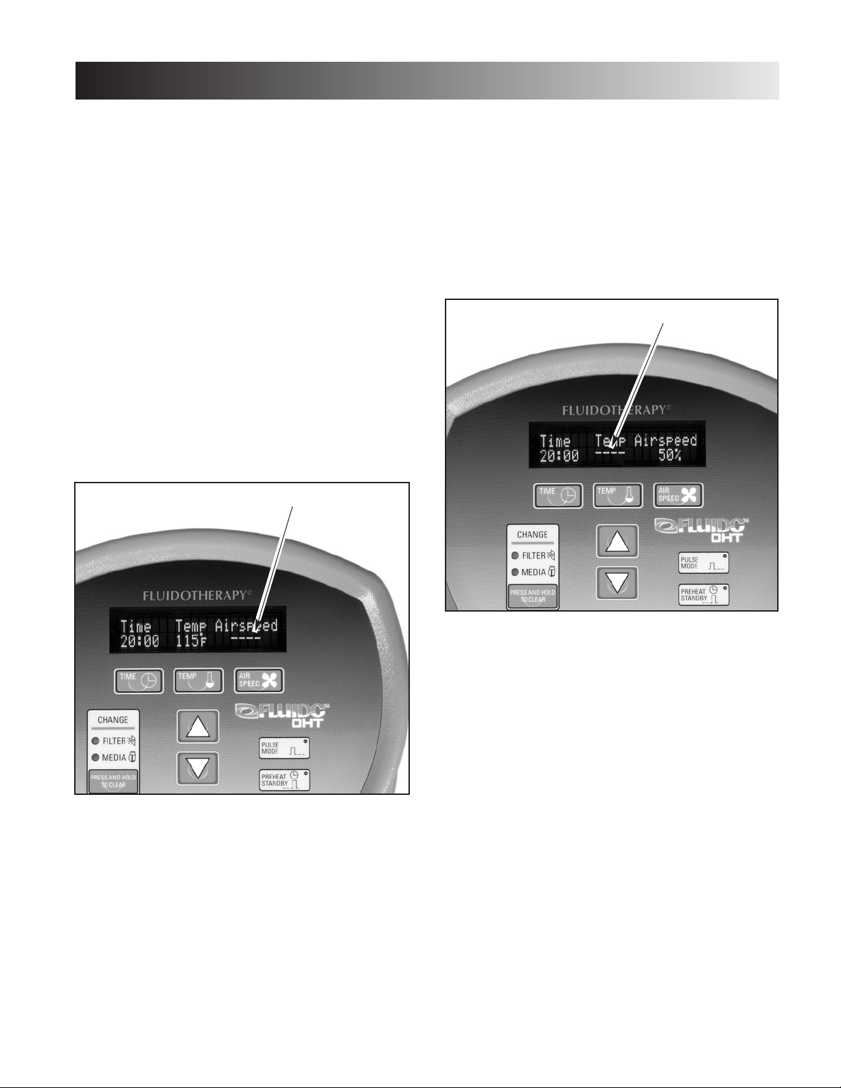
Motor/Blower Error
A. Should the software detect a problem within the
operation of the Blower/Motor, the display will
show four dashes beneath “AIRSPEED” on the
control panel LCD.
B. If this indicator is visible, there could be several
possible reasons:
• The intake filters are clogged and require
cleaning.
• The motor has overheated and requires a
cooling period before operation is resumed.
• The Distributor is clogged and requires
changing.
• The Cellex Medium has entered the heat
cavity of the unit and is restricting the air flow.
Should this indicator be visible, remove the
unit from service immediately. Perform any
and all maintenance and repair necessary
before the unit is placed back into service.
Refer to the appropriate sections of this
manual for proper removal and replacement
procedures.
Temperature Sensor Error
A. Should the Temperature Sensor experience
problems the software will display four dashes
beneath “Temp” on the LCD.
Should this occur the system may “Lock Up,”
preventing any further operation of the unit. This
error could be caused by several different
problems including:
• The intake filters are clogged and require
cleaning.
• The Temperature Sensor is faulty and requires
replacement.
• The Distributor is clogged and requires
changing.
• The Cellex Medium has entered the heat
cavity of the unit and is restricting the air flow.
B. Reset the Temperature Sensor by turning the
unit Off. Press and hold the “Stop” button for
ten to fifteen seconds. Release the “Stop”
button and turn the unit On. It will be necessary
to reset the Clock (refer to Users Manual). If the
Error persists, remove and replace the
Temperature Sensor. If the problem continues to
persist, replace the pc board in the control
panel. Refer to the appropriate section of this
manual for proper removal and replacement
procedures.
BBLLOOWWEERR//MMOOTTOORR PPRROOBBLLEEMM
IINNDDIICCAATTOORR..
TTEEMMPPEERRAATTUURREE SSEENNSSOORR
PPRROOBBLLEEMM IINNDDIICCAATTOORR..
Page 12

Fluido DHT™Dry Heat Therapy Unit
10
TROUBLESHOOTING
FFlluuiiddoo DDHHTT SSyysstteemm TTeessttiinngg
AA.. GGeenneerraall
11..
The following information is intended to aid in
troubleshooting the major components of the
DHT Units to “Board Level” only. These tests are
OEM standard testing procedures and methods
used at the factory before shipment of any Fluido
unit.
22..
Due to the complex nature of the technology
utilized by Chattanooga Group, the recommended
troubleshooting techniques are to determine “Bad
Board” and board replacement only. No board
component level troubleshooting is recommended
nor will information or parts be supplied by
Chattanooga Group. Any board component level
troubleshooting performed will be at sole risk and
liability of the Service Technician performing such
troubleshooting techniques.
33..
Once the PC Board has been determined as bad,
replace the board only with Chattanooga Group
OEM replacement parts and hardware.
BB.. SSppeecciiaall TToooollss,, FFiixxttuurreess && MMaatteerriiaallss RReeqquuiirreedd
11..
Certain tests require the use of special tools
and fixtures. These will be listed at the particular
test where they are required. Testing with any
other special tool or fixture other than those
stated could give erroneous readings or test
results. Always perform the tests exactly as stated
to ensure accurate results.
22..
Standard test equipment settings will be listed for
each test performed to aid in performing the test
to OEM standards and ensure proper readings.
33..
The troubleshooting and repair of the Fluido DHT
units, should be performed only by authorized
technicians trained and certified by Chattanooga
Group.
CC.. EEqquuiippmmeenntt RReeqquuiirreedd
11..
Digital Multimeter
22..
Dielectric Withstand (Hi-Pot) and ground
resistance tester.
33..
Milliohm Meter.
44..
Calibrated Thermometer
55..
Calibrated Stop Watch
NNOOTTEE::
Adjust Dielectric Withstand tester to indicate fault with
120k Ohm Load across the output when at specified test
voltage.
66.. RReeqquuiirreedd SSAAEE TToooollss
#1 Phillips Screwdriver
#2 Phillips Screwdriver
5/16, 7/16, 9/16, 1/2, 5/32, and 11/32 Wrenches
1/8 and 5/32 Allen Wrenches (or drill bits)
Utility Knife
Wet/Dry Vacuum
77.. RReeqquuiirreedd LLuubbrriiccaannttss
Silicon based multipurpose grease.
88.. RReeqquuiirreedd SSeeaalliinngg CCoommppoouunndd
100% pure silicon sealant
NNOOTTEE::
The tool, lubricant and sealing compound requirements will
be listed at the respective removal and replacement
procedures throughout this manual.
!
CAUTION
The following tool, lubrication, and sealing compound
requirements are critical to the component removal and
replacement of the Fluido DHT unit.
All hardware,bolts, nuts and screws used to assemble the
Fluido DHT are SAE Standard. Due to the size of these
components no metric equivalent is available. Therefore,
it will be necessary to obtain the proper size tools for
removal and replacement of certain components.
The lubricants and sealing compounds listed below are
crucial in the assembly of certain components to ensure
patient safety and efficient operation of the unit. Use only
the recommended products listed or an approved
equivalent possessing the same properties and qualities.
Page 13
VViissuuaall IInnssppeeccttiioonn
AA.. GGeenneerraall
Visually inspect the Fluido DHT unit. A visual
inspection can, to an experienced Technician,
indicate possible abuse of the unit and/or internal
problems.
GGrroouunndd RReessiissttaannccee TTeesstt
AA.. VVoollttaaggee SSppeecciiffiiccaattiioonnss
MMooddeell 11448800
. . . . .
Input: 120 VAC~50/60 Hz, 40 Watts
MMooddeell 11448811
. . . . Input: 230 VAC~50/60 Hz, 40 Watts
BB.. SSppeecciiffiiccaattiioonn
Maximum Acceptable Resistance: 500 milliohms
CC.. EEqquuiippmmeenntt RReeqquuiirreedd
Milliohm Meter
DD.. TTeesstt
Place unit on level work surface.
Place one meter probe on the ground prong of power
cord and the other to any exposed metal or screw on
the unit.
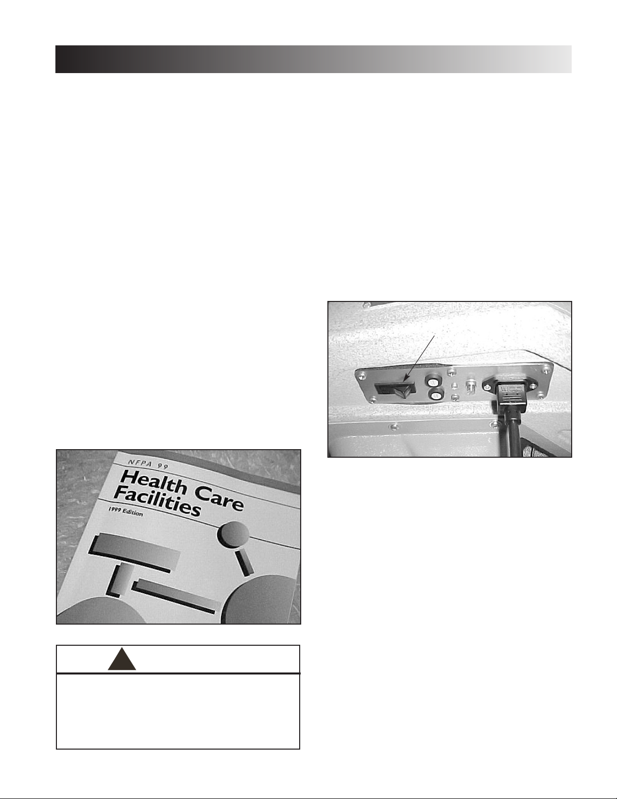
LLeeaakkaaggee TTeessttss
TTeesstt VVoollttaaggee SSppeecc
. . . . . . . . . . . . . . . . . . . . . . . . . . . .
1000V
Conduct all necessary leakage tests as required per
“Chapter 7 Electrical Equipment” of the 1999, or later,
edition of the NFPA (National Fire Protection
Association) “Health Care Facilities” standards.
RReesseettttiinngg FFlluuiiddoo DDHHTT FFaaccttoorryy DDeeffaauulltt SSeettttiinnggss
To reset all factory default settings of the unit, turn unit
Off. Depress and hold the “Clear” button on the control
panel and turn unit on simultaneously.
PPrreehheeaatt TTeesstt
AA.. TToooollss && EEqquuiippmmeenntt RReeqquuiirreedd
Calibrated Thermometer
BB.. PPrreehheeaatt TTeesstt PPrroocceedduurreess
Power Requirements:
Model 1480. . . . . . . . . . . . . . . . . . . . . . 120 VAC
Model 1481. . . . . . . . . . . . . . . . . . . . . . 230 VAC
Plug the unit power cord
to a grounded electrical
service receptacle conforming to
the applicable
national and local electrical codes.
Turn unit power switch On.
Start the preheat function by depressing the
“PREHEAT STANDBY” button on the control panel.
After approximately 30 seconds, the Blue LED
should illuminate.
After approximately 30 minutes or less, depending
on the ambient temperature of the medium, the
blower should reduce from 50% airspeed to 5%
airspeed and the Temp indicator should read the
temperature of the Cellex
®
medium. Insert the
calibrated thermometer into medium and record the
reading. The Temperature reading should be ± 5 °F
or 3 °C of Spec below.
Preheat Default Temp. Spec . . . . 115 °F (46.11 °C)
A temperature reading outside the specified range
may be caused by clogged intake filters, clogged
distributor, faulty temperature sensor, or faulty
heating element. Refer to the appropriate section for
the proper removal and replacement procedures.
Fluido DHT™Dry Heat Therapy Unit
TROUBLESHOOTING
11
!
UNIT FAILING DIELECTRIC WITHSTAND AND/OR LEAKAGE
TESTS COULD INDICATE SERIOUS INTERNAL SYSTEM
PROBLEMS.
DO NOT PLACE UNIT BACK INTO SERVICE! SEND UNIT TO
FACTORY FOR REPAIR!
DO NOT ATTEMPT TO REPAIR IN THE FIELD!
POWER
SWITCH
WARNING
Page 14

Fluido DHT™Dry Heat Therapy Unit
12
PPuullssee MMooddee TTeesstt
AA.. TToooollss && EEqquuiippmmeenntt RReeqquuiirreedd
Calibrated Stop Watch
BB.. PPuullssee MMooddee TTeesstt PPrroocceedduurreess
Reset the factory defaults. Refer to the section
entitled “Resetting Fluido DHT Factory Default
Settings”on page 11.
Press the “PULSE MODE” button, the Blue LED should
illuminate. Press the “TREATMENT START” button.
Using the calibrated stop watch, time the pulses of
the unit while it is running. Record the readings taken
and verify the settings you entered for the pulse.
The unit should pulse at approximately four seconds
on, after reaching its maximum blower speed, and
four seconds off.
TTrreeaattmmeenntt TTiimmee TTeesstt
AA.. TToooollss && EEqquuiippmmeenntt RReeqquuiirreedd
Calibrated Stop Watch
BB.. TTrreeaattmmeenntt TTiimmee TTeesstt
With the unit On, press and release the “Time”
button. Using the down arrow, adjust the time to
“1:00”.
Press “TREATMENT START” and time with the
Calibrated Stop Watch. Record the reading.
TTrreeaattmmeenntt TTiimmee SSppeecc
. . . . . . . . . . . . 1 minute ± 1 second
AAiirr SSppeeeedd TTeesstt
AAiirrssppeeeedd TTeesstt PPrroocceedduurreess
Turn unit On. Press “Treatment Start”. While unit is
running, press the “Air Speed” button. Use the Up
and Down arrows to adjust the air speed to 100%
and back down to 5%. Listen for the increase and
decrease in the blower speed. Look for increased
and decreased fluidization of the medium in the
reservoir.
CCoonnttrrooll PPaanneell LLoocckk--UUpp
Should the control panel Lock Up and not allow any
operation of the unit or parameter changes. Reset the
unit Factory Defaults (Refer to the section entitled
“Resetting Fluido DHT Factory Default Settings”on
page 11). If the condition persists, replace the Control
Panel PC Board. Refer to “Control Panel PC Board” on
page 13 for removal and replacement procedures.
NNOOTTEE::
For proper operation and setting of the unit parameters
outside the Factory Defaults, refer to the User Manual
for the Fluido DHT.
TROUBLESHOOTING
Page 15
Fluido DHT™Dry Heat Therapy Unit
13
SSlleeeevveess aanndd CCeelllleexx
®®
Refer to the Fluido DHT User Manual for the proper
removal and replacement of the following items:
Unit End Sleeves
Unit Top Sleeves
Cellex Medium
Intake Filters
CCoonnttrrooll PPaanneell PPCC BBooaarrdd
AA.. TToooollss && EEqquuiippmmeenntt RReeqquuiirreedd
Small Flat Blade Screwdriver
5/16 Open End Wrench
#2 Phillips Screwdriver
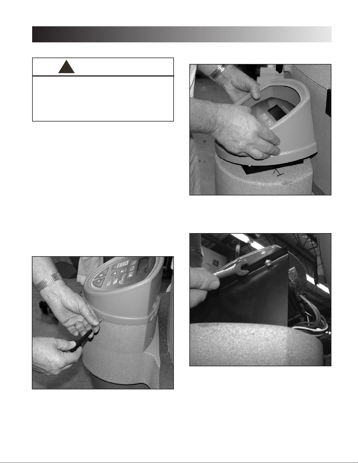
BB.. RReemmoovviinngg tthhee CCoonnttrrooll PPaanneell PPCC BBooaarrdd
1. Remove the three retaining screws from the
Control Panel Bezel.
2. Carefully remove the Bezel from the Control
Panel.
3. Remove the four retaining nuts securing the
Control Panel to its mounting base (two on each
side).
REMOVAL & REPLACEMENT
!
UNPLUG THE UNIT FROM THE POWER SOURCE BEFORE
ATTEMPTING ANY REMOVAL OR REPLACEMENT
PROCEDURES TO PREVENT ELECTRICAL SHOCK. FOLLOW
ELECTRONIC REPAIR PROTOCOLS FOR GROUNDING TO
PREVENT DAMAGE TO THE ELECTRONIC COMPONENTS
FROM STATIC ELECTRICITY.
WARNING
Page 16

Fluido DHT™Dry Heat Therapy Unit
REMOVAL & REPLACEMENT
14
4. Remove the Control Panel from the mounting
base.
5. Remove the five wiring harnesses from the PC
Board.
CC.. RReeppllaacciinngg tthhee CCoonnttrrooll PPaanneell PPCC BBooaarrdd
To replace the control panel PC board, reverse
steps 1 through 7 of “Removing the Control Panel
PC Board” starting on page 13.
NNOOTTEE::
Keep in mind the following when
replacing the Control Panel PC Board:
• Attach the connector with the two
brown wires to the heater terminal.
• Attach the connector with one brown
wire and one blue wire to the line
terminal.
• Attach the connector with one black
wire and one white wire to the motor.
• Attach the small, three- wire
connector wires to the speed
terminal.
• Attach the small, two-wire connector
to the temperature terminal.
Page 17

Fluido DHT™Dry Heat Therapy Unit
15
REMOVAL & REPLACEMENT
FFlluuiiddoo HHeeaatteerr
AA.. TToooollss RReeqquuiirreedd
Wet/Dry Vacuum 1/8 Allen Wrench
7/16 Wrench #1 Phillips Screwdriver
Wire Cutters Hammer
BB.. RReemmoovviinngg tthhee FFlluuiiddoo HHeeaatteerr
1. Remove lid completely from unit.
2. Using the wet/dry vacuum, remove the Cellex from
the tub.
3. Remove the seven screws from the perforated
metal at the bottom of the tub.
4. Using the wet/dry vacuum, remove the newly
exposed, excess Cellex.
NNOOTTEE::
When vacuuming, be careful not to
damage the temperature sensor.
5. Remove the rubber tub insert closest to the control
panel. Then, remove the other rubber tub insert.
6. Using the wet/dry vacuum, remove the newly
exposed, excess Cellex.
7. Remove the ten hex screws from the bottom of the
tub.
!
CAUTION
Make certain to vacuum the screw heads at the base of
the tub. This will ensure that Cellex will not fall in the
standoff’s holes, and you will not round out the heads of
the screws when re-inserting them.
!
CAUTION
Make sure to remove the excess Cellex from the heads of
the hex screws to avoid rounding out the heads of the
screws.
Page 18

Fluido DHT™Dry Heat Therapy Unit
REMOVAL & REPLACEMENT
16
8. Cut and remove the plastic band securing the
temperature sensor.
9. Remove the perforated metal.
10.Remove the diffuser baffle.
11.Remove the diffuser foam.
12.Remove bottom (and final) piece of perforated
metal.
13. Using the screwdriver, remove the ground screw.
14.Follow steps 1-3 listed in “Removing the Muffler
Cover and Muffler ” on page 19.
15.Remove the two hex screws from the motor
support bracket.
!
CAUTION
Make certain that you do not spill any Cellex into the
heater enclosure cavity.
Page 19

Fluido DHT™Dry Heat Therapy Unit
17
REMOVAL & REPLACEMENT
16.Using a 7/16 wrench, remove the five hex nuts
from the heater housing, as well as the motor
support bracket.
17.Use the claw end of the hammer to gently and
slightly pull up the edge of the unit in order to get
clearance for the overtemp sensor.
18.Slide the heater assembly out.
19.Using wire cutters, cut the wire between the
brown and black wires.
20.Unplug the dark blue wire from the inlet side of
the line filter.
21.Using the wire cutters, cut the black heater
indicator light wire from the switch plate
assembly.
Page 20

Fluido DHT™Dry Heat Therapy Unit
18
REMOVAL & REPLACEMENT
CC.. RReeppllaacciinngg tthhee FFlluuiiddoo HHeeaatteerr
NNOOTTEE::
Before attempting to replace the Fluido
heater, Vacuum any loose Cellex that may
be in the motor housing or heater
housing.
To replace the Fluido heater, reverse steps 1 through
21 of “Removing the Fluido Heater” on pages 15-17
(i.e., instead of cutting wires, simply solder or
reattach them).
NNOOTTEE::
When replacing the Fluido heater, be sure
to use a new diffuser (14119).
FFlluuiiddoo DDiiffffuusseerr
AA.. TToooollss RReeqquuiirreedd
Wet/Dry Vacuum #2 Phillips Screwdriver
Wire Cutters 7/16 Wrench
BB.. RReemmoovviinngg tthhee FFlluuiiddoo DDiiffffuusseerr
To remove the Fluido diffuser, following steps 1 - 13
of “Removing the Fluido Heater” on pages 15-16.
CC.. RReeppllaacciinngg tthhee FFlluuiiddoo DDiiffffuusseerr
To replace the Fluido diffuser, reverse steps 1 through
13 of “Removing the Fluido Heater” on pages 15-16.
FFlluuiiddoo MMoottoorr
AA.. TToooollss RReeqquuiirreedd
#2 Screwdriver
BB.. RReemmoovviinngg tthhee FFlluuiiddoo MMoottoorr
Before attempting to remove the Fluido motor, you
must complete steps 1 through 3 of “Removing the
Muffler and Muffler Cover” on page 19.
1. Remove the five screws outside of the motor
support plate, being sure to hold the plate while
removing the last screw.
2. With one hand, hold the motor while using your
other hand to disconnect the motor wiring from the
harness. See the following 2 figures.
!
CAUTION
Be careful not to damage the metal shaft on the end of
the motor. See the following figure.
!
CAUTION
Hold the motor support plate before removing the last
screw. Otherwise, the motor may fall from the housing.
Page 21

Fluido DHT™Dry Heat Therapy Unit
19
REMOVAL & REPLACEMENT
CC.. RReeppllaacciinngg tthhee FFlluuiiddoo MMoottoorr
To replace the Fluido Motor, reverse steps 1 and 2 of
“Removing the Fluido Motor” on page 18.
MMuufffflleerr aanndd MMuufffflleerr CCoovveerr
AA.. TToooollss RReeqquuiirreedd
1/8 Allen Wrench
BB.. RReemmoovviinngg tthhee MMuufffflleerr CCoovveerr aanndd MMuufffflleerr
1. Remove the 14 screws that secure the muffler
cover.
2. Slide the muffler cover down on the shaft.
3. Remove the foam insert from inside the muffler
cover.
NNOOTTEE::
Notice the hole in the foam insert. You
will need to line up this hole with the
Morris taper on the shaft when you
re-assemble the muffler.
CC.. RReeppllaacciinngg tthhee MMuufffflleerr CCoovveerr aanndd MMuufffflleerr
To replace the muffler and muffler cover, reverse
steps 1-3 of “Removing the Muffler Cover” on this
page.
Page 22

Fluido DHT™Dry Heat Therapy Unit
20
REMOVAL & REPLACEMENT
CCaasstteerrss
AA.. MMaatteerriiaallss aanndd TToooollss RReeqquuiirreedd
9/16 Wrench
(4) Caster - 14135
Base Frame- 14104
(4) 3/8-16 Black Acorn Nuts - 14146
BB.. RReemmoovviinngg tthhee CCaasstteerrss
1. Make sure casters are locked by pressing the
metal flap until the wheel does not move. This will
prevent the shaft of the caster from moving while
you are attempting to remove it.
2. Remove each of the four 3/8-16 black acorn nuts.
3. Lift the base to remove each of the shafts of the
four casters from the unit.
CC RReeppllaacciinngg tthhee CCaasstteerrss
1. Make sure caster is locked before attempting to
install.
2. Place one caster on each corner of the base, and
attach with four 3/8-16 black acorn nuts.
Page 23

Fluido DHT™Dry Heat Therapy Unit
REPLACEMENT PARTS
21
PART
NO.
DESCRIPTION
14206 HARNESS RECEPTACLE TO POWER SWITCH
14207 HARNESS O.T. TO STAT H.E.
14208 HARNESS MOTOR SPEED CONTROL
14209 LINE FILTER BRACKET
14211 HARNESS CONTROL INTERCONNECT
14213 HARNESS GROUND 7"
14214 HARNESS GROUND 24"
14215 HARNESS TEMP SENSOR
14219 1/4-20 X 5/8 SANDWICH MOUNT
14220 10 x 24 INSULATION MOTOR HOUSING
14221 5' X 4" INSULATION MOTOR HOUSING
14222 5" X 5" INSULATION MOTOR HOUSING
14223 9" X 9" INSULATION MOTOR HOUSING
14225 HARNESS FUSE TO POWER SWITCH 220V
14226 HARNESS POWER SWITCH TO LINE FILTER
14227 HARNESS O.T. STAT TO H.E.
14228 HARNESS LINE FILTER GROUND TO CHASSIS
14229 ELBOW SLEEVE ASSEMBLY
14230 INLET FILTER 19155K22
14231 FILTER NYLON MESH 3-5/8" SQ.
14232 GLIDE ETS 32 X 50 D80153
14233 USER INTERFACE BRACKET PAINTED
14234 MOTOR HOUSING SUPPORT PAINTED
14235 FOAM INSERT
14236 MOTOR SUPPORT PLATE PAINTED
14237 SET SCREW 6-32 X 3/4 91375A151
14238 SPACER NYLON 1/2 ODX1/4 ID x 5/8 94639A143
14239 SCREW #1 X 3/8" 90253A033
14240 POP RIVET 1/8 X 5/8 ALUMINUM 97447A135
14241 CAPTIVE STUD 6/32 X 3/8 93580A016
14244 RIVNUT 10-32 S10P175
14245 STRAIN RELIEF PLATE FLUIDO DHT
14247 230V. MOTOR HOUSING ASSY.
14251 HYDRAULIC LIFT (CHROME) 4500
14253 FUSE HOLDER SCHURTER
14254 INLET AC FAST CONNECT
14255 10 AMP. 5MM X 20MM (FUSE)220V 3 AG SLOW BLOW
14259 2-56 X 1/4" PAN HD.PHIL PLT.
14260 MOTOR ASSY. 120V.
14261 MOTOR ASSY. 230V.
PART
NO.
DESCRIPTION
14105 BASE ASSEMBLY FLUIDOTHERAPY
14 111 PATIENT TUB LID FLUIDO DHT
14113 LID LATCH FLUIDO DHT
14116 SCREW #2 X 3/8 PAN HD. PHIL.
14117 DISTRIBUTOR PLATE FLUIDO DHT
14118 PLEXIGLASS TRIM FLUIDOTHERAPY
14119 FOAM DISTRIBUTOR PLATE FLUIDOTHERAPY
14120 TUB DRAIN PLUG FLUIDOTHERAPY
14122 6-32 X 1/2 OD X1 LG CERAMIC STD. OFF
14123 6-32 X 1/2 OD X 1-1/2 LG CERAMIC STD.
14124 GASKET TUB LID FLUIDOTHERAPY
14125 MANUAL USER FLUIDOTHERAPY
14128 MANUAL SERVICE FLUIDOTHERAPY
14130 SLEEVE ASSEMBLY FLUIDO DHT
14135 CASTER TENTE 006874 FLUIDO DHT
14136 FOAM MUFFLER FLUIDO DHT
14137 MUFFLER COVER FLUIDO DHT
14139 BOTTOM W/ MOTOR HOUSING FLUIDO DHT
14145 U.I. DISPLAY LENS FLUIDO DHT
14146 ACORN NUT FLUIDO DHT
14148 SCREW 10-32 x 3/4 BUTT. HD. SOC
14150 SCREW 10-32 X 1 BUTT HD SOC
14151 SWITCH PLATE GASKET FLUIDO DHT
14160 SCREW 10-32 X 1/2 BUTT HD SOC
14161 HEX STANDOFF 6-32 X .875 ALUM.
14162 MULIT STACK ADAPTER
14166 USER INTERFACE COVER FLUIDO DHT
14168 PLASTIC COVER FLAT FLUIDO DHT
14169 SLEEVE RETAINING CLIP FLUIDO DHT
14170 POWER CORD FLUIDO DHT
14171 SWITCH PLATE FLUIDO DHT
14174 GASKET MOTOR MOUNTING PLATE
14175 ELBOW SLEEVE FLANGE FLUIDO DHT
14184 TOP HEATER SHIELD METAL
14185 BOTTOM HEATER SHIELD METAL
14188 SPONGE GASKET 3/4" X1/4" ADHES.
14189 HARNESS CONTROL POWER SWITCH
14202 HARNESS CONTROL TO HEATER SUB
14203 HARNESS HEATER TO INDICATOR
14204 HARNESS FUSE TO RECEPTACLE
Page 24

Fluido DHT™Dry Heat Therapy Unit
REPLACEMENT PARTS
22
PART
NO.
DESCRIPTION
14262 HARNESS RECP. TO SWITCH PLATE
14263 HARNESS RECP. GROUND TO GROUND
14265 1000 watt 110 volt heater
14266 1000 watt 220 volt heater
14268 TOP DIFFUSER FLUIDO DHT
14269 DIFFUSER AIR BAFFLE FLUIDO DHT/24 ga. carbon
14270 DIFFUSER AIR BAFFLE FLUIDO DHT/adhesive backed foil
14272 HOUSING BRACE SPACER
14274 HOUSING BRACE(PAINTED #)
14275 FOAM INSERT
14276 POWER SWITCH
14277 ADAPTER 1/8 NPT 15090-1
14279 heater indicator light blue 230v
14284 HEATER ENCLOSURE ASSY 120V.
14285 POP RIVET 1/8"
14286 FICHE PAPER 10 MIL THK.
14287 FITTING ADAPTER 1/8 TO 10-32 15090-1
14288 heater indicator light blue 120v
14291 Thermal over temp switch
14293 GALVANIZED WIRE CLOTH 6X6 MESH .120 WIRE DIA.
14294 HEATER INCLOSURE MESH
14295 HEATER ENCLOSURE ASSY 230V.
14296 MOTOR HOUSING HEATER SCREEN
14299 CONTROL PNL.ASSY 120V
14300 MOTOR ASSY 230V.
14301 MOTOR ASSY 120V.
14302 Motor housing warning label
14304 1" Almn Standoff
Page 25

Fluido DHT™Dry Heat Therapy Unit
23
DIAGRAMS
Base Assembly -
120v and 230v
Page 26

Fluido DHT™Dry Heat Therapy Unit
24
DIAGRAMS
Control Panel Assembly 120v and 230v
Page 27

Fluido DHT™Dry Heat Therapy Unit
25
DIAGRAMS
Lid Assembly -
120v and 230v
Page 28

Fluido DHT™Dry Heat Therapy Unit
26
DIAGRAMS
Switch Plate Assembly 120v
Page 29

Fluido DHT™Dry Heat Therapy Unit
27
DIAGRAMS
Switch Plate Assembly
- 230V
Page 30

Fluido DHT™Dry Heat Therapy Unit
28
DIAGRAMS
Wiring Diagram 120v
Page 31

Fluido DHT™Dry Heat Therapy Unit
29
DIAGRAMS
Wiring Diagram 230v
Page 32

Fluido DHT™Dry Heat Therapy Unit
30
DIAGRAMS
Heater Enclosure Assembly 120v
Page 33

Fluido DHT™Dry Heat Therapy Unit
31
DIAGRAMS
Heater Enclosure Assembly -
230v
Page 34

Fluido DHT™Dry Heat Therapy Unit
32
DIAGRAMS
Motor & Support Assembly 120v
Page 35

Fluido DHT™Dry Heat Therapy Unit
33
DIAGRAMS
Motor & Support Assembly230v
Page 36

Fluido DHT™Dry Heat Therapy Unit
34
DIAGRAMS
Motor Housing Assembly -
120v
Page 37

Fluido DHT™Dry Heat Therapy Unit
35
DIAGRAMS
Motor Housing Assembly -
230v
Page 38

Fluido DHT™Dry Heat Therapy Unit
36
DIAGRAMS
Motor Housing Assembly
- 120v
Page 39

Fluido DHT™Dry Heat Therapy Unit
37
DIAGRAMS
Motor Housing Assembly
- 230v
Page 40

Fluido DHT™Dry Heat Therapy Unit
38
DIAGRAMS
F IT PP /N 114 22 1 SS N UG AA GA IN S T IIN S ID E WW A L L
A ND TT U CK UUN D E R FF L AN G E .
14233
1413 9
60756 (4)
14245
14150
14148
A PP L Y TTH I N FF ILM OO F
C LE A R SS IL IC ON E
B E TW E EN 1141 39 && 114 2 45
14244
F IT PP /N 11 422 1 SS NU G AA GA I NS T IIN S ID E WW A L L
A N D TT UC K UU N D ER FF L AN G E .
B RE A K TT A B OO FF GGR O U N D
LU G SSI D E
60059
14178
60014
14209
1416 2
14304
14284
14299
14166
14239 (3)
Motor Housing Assembly 120v
Page 41

Fluido DHT™Dry Heat Therapy Unit
39
DIAGRAMS
BR E A K TTA B OOF F GG RO UN D
L UG SS I DE
14209
6001 4
1430 4
14178
6005 9
FI T PP /N 11 4221 SS NU G AAG A IN ST II NS ID E WW AL L
A ND TT UC K UU ND E R FF L AN G E.
A PP LY TT H IN FF ILM OOF
CL E AR SS ILI CO NE
BE T WE E N 114 139 && 11 42 45
14139
FI T PP /N 114 22 1 SS NU G AAG A IN ST II NS ID E WW AL L
A ND TT UC K UU N D ER FF LA N GE .
14244
14162
14244
60756 (4 )
14245
1415 0
14233
14148
14166
14239 (3)
14295
14299
Motor Housing Assembly -
230v
Page 42

Fluido DHT™Dry Heat Therapy Unit
40
DIAGRAMS
Final Assembly 120v
Page 43

Fluido DHT™Dry Heat Therapy Unit
41
DIAGRAMS
Final Assembly -
230v
Page 44

Fluido DHT™Dry Heat Therapy Unit
42
DIAGRAMS
AS SHOWN USIN G (14161) & (70099)
NOTE: STANDOFFS S HOULD BE FIXE D TO (14117)
14126
14152
14269
70099 (5)
14117
14119
71090
14117
14110
14148 (10)
68876 (10)
TRIM FOAM ALONG OUTSIDE
EDGE OF HOUSING
AFTER ASSEMBLY
14240
14161 5
Final Assembly 120v
Page 45

Fluido DHT™Dry Heat Therapy Unit
43
DIAGRAMS
1411 0
70099 (5)
1411 9
1411 7
6887 6 (10)
14148 (10)
T R I M FFO A M AA L O N G OO U T S I D E
E D G E OOF HH O U S I N G
A F T E R AA S S E M B L Y .
1415 2
14240
1424 3
4.00
4.00
4.00
4.00
NOTE: STANDOFFS SHOULD BE FIXED TO (14117)
AS SHOWN USING (14161) & (70099).
14161 (5)
14117
14269
71090
Final Assembly -
230v
Page 46

Fluido DHT™Dry Heat Therapy Unit
44
DIAGRAMS
14102
14240
14113
14120
21799
60057
14130
14105
14240
4 PLACES.
INSTALL AS SHOWN
INSTALL AS SHOW N
4 PLACES.
DR ILL 11/8 DDIA . HH OL ES TT HR U
FO R RR IVE TS .
DR IL L 11/8 DDI A. HH OL ES TTHR U
FO R RR IVE TS. TT UB && LL ID
MU ST BB E DD RI LL ED TTOG ETH ER
US IN G DDR ILL JJ IG .
14273
70099
14275 (2)
14268
31805
14169
IN STA LL SSLE EV E RRE TAI NE R CCL IP
AS SSHO WN 44-PPL ACE S
71090
Final Assembly 120v
Page 47

Fluido DHT™Dry Heat Therapy Unit
45
DIAGRAMS
14102
14240
14113
14120
21799
60057
IINN SSTTAALL LL SSLL EEEEVV EE RR EETTAA IINN EERR CC LLII PP
AASS SSHHOOWW NN 44-PP LL AACCEE SS
14169
31805
14130
14240
4 PLACES.
INSTALL AS SHOWN
INSTALL AS SHOWN
4 PLACES
14105
DDRRIILL LL 11//88 DD IIAA .. HHOOLL EESS TT HH RRUU
FF OO RR RR IIVV EE TT SS..
DDRRIILL LL 11//88 DDIIAA.. HH OOLLEE SS TTHHRRUU
FF OO RR RRIIVV EE TT SS.. TTUUBB && LL IIDD
MM UUSSTT BBEE DD RR IILL LLEEDD TTOO GGEETT HH EE RR
UUSSII NNGG DDRRIILL LL JJIIGG..
70099
14273
14268
14275 (2)
71090
Final Assembly -
230v
Page 48

Fluido DHT™Dry Heat Therapy Unit
46
WARRANTY
Chattanooga Group ("Company") warrants that the Fluido DHT units ("Product") are free of defects in material and workmanship. This warranty shall
remain in effect for two years (24 months) from the date of original consumer purchase. If this Product fails to function during the two year warranty
period due to a defect in material or workmanship, Company or the selling dealer will repair or replace this Product without charge within a period of
thirty (30) days from the date on which the Product is returned to the Company or the dealer.
All repairs to the Product must be performed by a service center authorized by the Company. Any modifications or repairs performed by unauthorized
centers or groups will void this warranty.
The warranty period for replaceable intake filter(s) is 90 days.
The warranty period for sleeves is one year (12 months).
To participate in warranty coverage, this Product's warranty registration card (included with Product) must be filled out and returned to the Company by
the original owner within ten (10) business days of purchase.
This Warranty Does Not Cover:
Replacement parts or labor furnished by anyone other than the Company, the selling dealer or a certified Company service technician.
Defects or damage caused by labor furnished by someone other than Company, the selling dealer or a certified Company service technician.
Any malfunction or failure in the Product caused by product misuse, including, but not limited to, the failure to provide reasonable and required
maintenance or any use that is inconsistent with the Product User's Manual.
CCOOMMPPAANNYY SSHHAALLLL NNOOTT BBEE LLIIAABBLLEE IINN AANNYY EEVVEENNTT FFOORR IINNCCIIDDEENNTTAALL OORR CCOONNSSEEQQUUEENNTTIIAALL DDAAMMAAGGEESS..
Some states do not allow the exclusion or limitation of incidental or consequential damages, so the above limitation or exclusion may not apply to you.
To Obtain Service From Company or the selling dealer under this warranty:
1. A written claim must be made within the warranty period to the Company or the selling dealer. Written claims made to the Company
should be sent to:
4717 Adams Road
P.O. Box 489
Hixson, TN 37343 US
Telephone: (423) 870-2281
Tel (International): +1 (423) 870-7200
Facsimile: (423) 870-7200
Fax (International): +1 (423) 870-2046
and
2. The Product must be returned to the Company or the selling dealer by the owner.
This warranty gives you specific legal rights and you may also have other rights which vary from state to state.
The Company does not authorize any person or representative to create for it any other obligation or liability in connection with the sale of the Product.
Any representation or agreement not contained in the warranty shall be void and of no effect.
TTHHEE FFOORREEGGOOIINNGG WWAARRRRAANNTTYY IISS IINN LLIIEEUU OOFF AALLLL OOTTHHEERR WWAARRRRAANNTTIIEESS,, EEXXPPRREESSSSEEDD OORR IIMMPPLLIIEEDD,,
IINNCCLLUUDDIINNGG AANNYY WWAARRRRAANNTTYY OORR MMEERRCCHHAANNTTAABBIILLIITTYY OORR FFIITTNNEESSSS FFOORR AA PPAARRTTIICCUULLAARR PPUURRPPOOSSEE..
When the Fluido DHT unit requires service, or preventive maintenance, contact the selling dealer or Chattanooga Group Service
Department.
All units returned to the factory for service must include the following;
WWAARRRRAANNTTYY RREEPPAAIIRR//OOUUTT OOFF WWAARRRRAANNTTYY RREEPPAAIIRR
11..
Written statement containing the following information;
·
RGA Number- Obtain from Factory
·
Unit Model Number
·
Unit Serial Number
·
Contact person with Phone and Fax Numbers
·
Billing Address (for Out of Warranty Repair)
·
Shipping Address (Where to Ship Unit after Repair)
·
Detailed Description of Problem or Symptoms
22..
Copy of original invoice issued at purchase of the unit.
33..
Ship unit to Factory in the original container with all
accessories and information as required in item 1 above to:
Chattanooga Group
4717 Adams Road
Hixson, TN 37343
Phone: US: 1-800-592-7329
Canada: 1-800-361-3661
Outside US: +1-423-870-7200
FAX: 1-423-875-5497
FAX (International): +1-423-870-2046
Web Address: www.chattgroup.com
Service to these units should be performed only by Service Technicians Certified by Chattanooga Group.
Page 49

ISO 13485 CERTIFIED
4717 Adams Road
P.O. Box 489
Hixson, TN 37343
U.S.A.
1-423-870-2281
1-800-592-7329
U.S.A.
1-800-361-6661 CANADA
+ 1-423-870-2046 OUTSIDE U.S.A. FAX
www.chattgroup.com
© 2003 Encore Medical
More Trusted Products from Chattanooga Group
Achiever
™
Supports
Fluido DHT
®
Dry Heat Therapy Units
A.E.R. Boot® and Compression System
Auto Edema Reduction Boot
Baseline®Measurement Instruments
Dynamometers, Goniometers, etc.
boo-boo pac
™
Child Size Bear-Shaped Cold Pack
Cambion
®
Shock Dampening Foot Care Products
Carpal-Trac
™
Carpal Traction Accessory
Cervical Traction System
Clinical Cervical Traction
Chattanooga Exerciser
™
Exercise Equipment
ColPaC
®
Chilling Units and Reusable Cold Therapy Products
Conductor Gel
™
Highly Conductive Ultrasound Gel
Contracture Products
Contracture Management Orthotic Products
CTS
™
Carpal Tunnel Stretching Device
DURA-STICK®Electrodes
Self-Adhesive Electrodes
EMG Retrainer®and
EMG Retrainer
®
I
R
Dual Channel Surface EMG
FlexiPAC
®
Reusable Hot and Cold Compresses
Fluidotherapy
®
Dry Heat Whirlpool Therapy Units
FORTE™ CPS
Electrotherapy Equipment
Gel Medex
™
Gel Mattress Overlay
HANDISIZER
™
Hand Exerciser
Hydrocollator
®
Heating Units and HotPacs
™
Intelect®Legend
Ultrasound and Electrotherapy Products
Magneciser
™
Exercise Equipment
Myossage
®
Massage Lotion
Nylatex
®
Elastic Wraps
OptiFlex®and
OptiFlex®S
Continuous Passive Motion
Opti-Ice
™
Cold Therapy System
Para-Care
®
Paraffin Wax Unit and Accessories
Pillow Perfect
™
Cervical Pillow Line
Pivotal Therapy System
™
Orthotics for the Spine
ProPower Pillow
™
Power Massage Pillow
PresSsion
®
Intermittent Compression
Pron Pillo
®
Positioning Pillow
QuikWrap
™
Deluxe Universal Belt System
SensaFlex
™
Hot and Cold Compress
SPORT-PAC
™
Soccer Ball Shaped Cold Pack
Theratherm
™
Digital Moist Heating Pad
Therma-Wrap
™
Hot and Cold Compression
Triton
®
Treatment and Traction Equipment
Tru-Trac
®
Traction Equipment
TX
®
Treatment and Traction Equipment
Vectra
™
Series
Electrotherapy products.
Versa Bath Seat
™
Aid to Daily Living
Wellness 1st
™
Back Support
Women’s Contour Back Support
Back Support
31971A
 Loading...