

Page 1
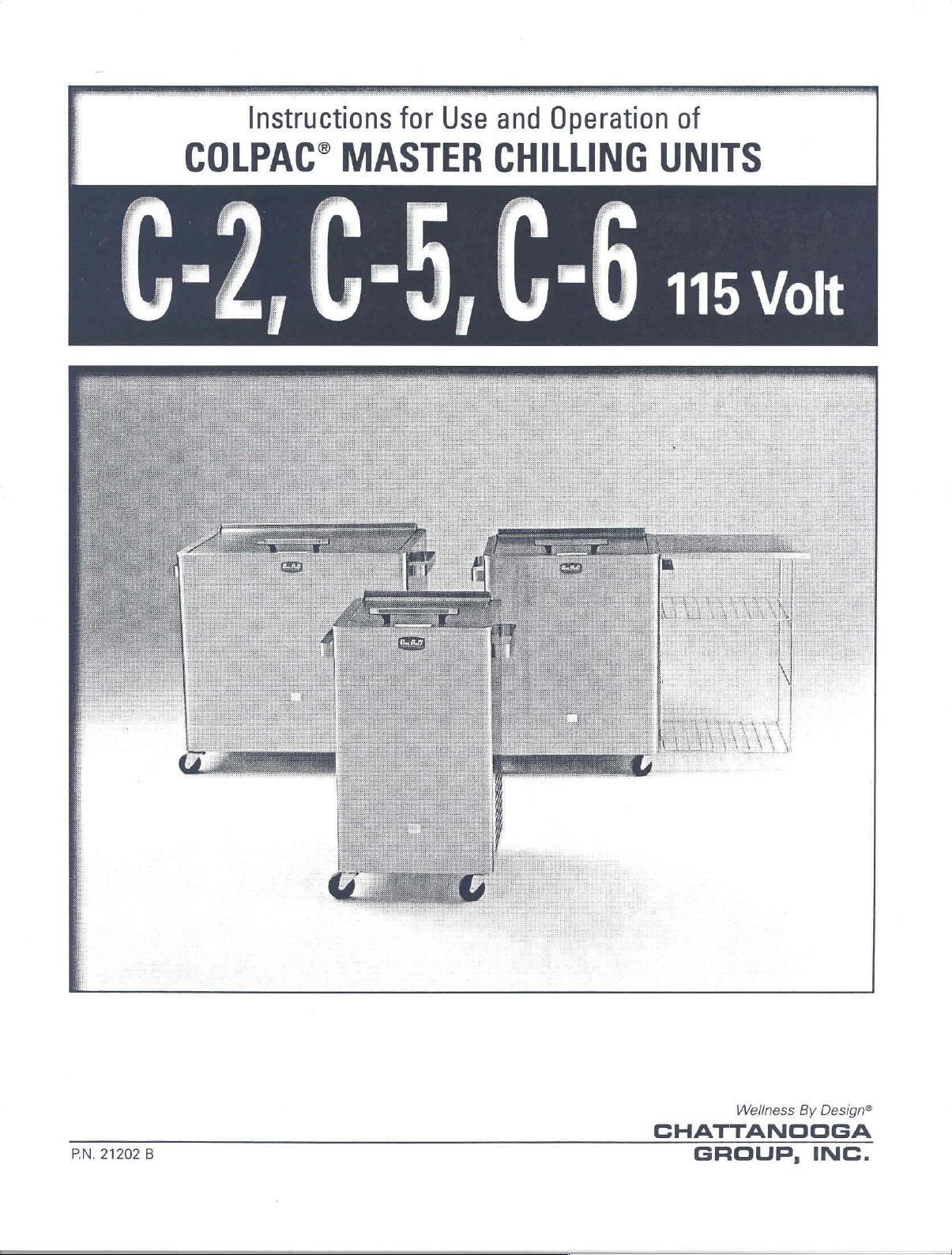
Instructions
for
Use
and
Operation
of
COLPAC®
MASTER
CHILLING
J
UNITS
115
Volt
РМ.
21202
В
Wellness
CHATTANOOGA
GROUP,
By
Design®
INC.
Page 2
Table
i2Menth
EOTEWOTÚ
Precautionary
Instructions
Géneralinformation:
General
Installationie
Maintenance
Trouble:
Technical
Parts
Parts
Parts
Parts
Parts
Parts
Electrical
of
Contents
Warranty.
Le
Instructions
for
Patient
Operating
spera...
Shoaingyx
Specifications
Drawing
List:
Drawing
list:
Drawing
List:
Model
Model
Model
Model
Schematic:
C-2
Model
ED
Model
C-6
oe
Instructions
Smnuyan
ees
ba
..............................
Care
and
2: : 5442
ο
ire
dx
bi,
oz
C-2
..............................
..................................
Gb
ss
40
388
C-6
.............................
.................................
Models
C-2,
utana,
SE a a A o
Comfort
280
messe
..........................
ei
üm 8 miele e 6
ο
ο
ο
gu
ae
fos
ans
C-5
..................
La
ο.
ο
46
nants
sas
ker
Se
TRILLO
and
C-6
aaa
siye
ae
er 8 a
fou
ο
Jags
sek
ber
RE
aa
.............
BD
sasi
şb 2
re
ani
qe
ee
ο.
a
qual
SR
NS
1
2
2
3
4
5
6
7
7
8
9
10
11
12
13
14
Page 3
12
Month
Chattanooga
Unit(s)
for
of
ty
replace
defective
replacement
What
2.
3.
(“Product”)
one
(1)
year
the
Product
period
because
or
repair
Product
This
Warranty
1.
Replacement
approved
Defects
approved
Any malfunction
ranty
period
if
the
malfunction
sonable
Warranty
Group,
during
or
Company
or
damage
Company
and
Inc.
is
free
from
the
the
of a defect
this
Product
is
returned
the
repaired
Does
parts
or
if
the
malfunction
or
necessary
(“Company”)
of
effects
date
of
original
warranty
in
without
to
Product
Not
Cover
or
labor
service
caused
service
failure
failure
agent.
by
agent.
in
maintenance.
warrants
in
material
consumer
period.
material
charge
the
Company
to
the
furnished
labor
furnished
the
Product
or
failure
is
caused
that
the
and
workmanship.
purchase
If
this
Product
and/or
workmanship,
within a period
or
the
consumer's
by
anyone
by
someone
while
is
by
it
is
not
caused
unreasonable
Colpac®
of
this
fails
to
function
of
30
dealer.
residence.
other
in
the
Company
than
other
possession
by a defect
use,
including
C-2,
C-5
This
warranty
Product
Company
days
the
Company,
than
of
in
and
shall
and
extends
during
from
or
material
the
or
the
the
the
dealer
Company,
the
owner
the
failure
C-6
Master
remain
to
one
year
selling
date
on
will
the
dealer
the
dealer
during
or
workmanship
to
provide
Chilling
in
effect
any
owner
warran-
dealer
which
ship
or
or
the
war-
will
the
the
an
an
or
rea-
Company
Some
above
Obtaining
To
obtain
by
the
1. A written
2.
This
to
state.
The
liability
the
warranty
shall
states
limitation
Service
service
following:
claim
The
is
Address:
Phone:
Product
warranty
Company
in
not
be
do
not
allow
or
exclusion
from
claim
made
gives
connection
shall
to
4717
P.O.
Hixson,
(800)
must
does
be
must
Box
you
not
liable
the
Adams
592-7329
void
for
the
Company
be
Company,
489
TN
37343
be
returned
specific
authorize
with
the
and
incidental
exclusion
may
not
or
the
made
Rd.
to
legal
any
sale
of
no
within
the
of
effect.
or
consequential
or
limitation
apply
Company
rights,
person
the
to
you.
selling
written claim
dealer
the
warranty
or
and you
or
Product.
damages
of
incidental
under
should
the
may
representative
Any
this
period
selling
representation
be
dealer
also
to
have
to
property
or
consequential
warranty,
Company
sent
to:
by
the
other
to
create
or
or
the
owner
or
the
owner.
rights
for
agreement
it
which
any
business.
damages,
must
do
selling
other
dealer.
vary
from
obligation
not
contained
so
or
the
abide
If
the
state
or
in
Page 4
Foreword
This
manual
Master
mation.
its
operating
However,
tions
Chilling
To
proper
may
obtain
operation,
the
owing
be
has
been
Units.
maximum
unit.
The
Chattanooga
made
at
prepared
It
contains
read
for
life
and
and
understand
instruction
specifications
Group's
any
time
without
the
owners
efficiency
this
put
forth
policy
obligation
and
operators
on
operation,
from
manual
in
this
of
continuous
on
of
precautions,
you
Colpac
thoroughly
manual
the
were
improvement,
part
of
the
Colpac®
maintenance
C-2,
C-5
and
and
follow
in
effect
Chattanooga
at
changes
Models
C-6
all
the
Group.
C-2,
and
units,
instructions
time
to
these
C-5
and
C-6
parts
infor-
and
to
aid
prior
of
publication.
specifica-
in
to
Precautionary
1.
CAUTION:
2.
CAUTION:
3.
WARNING:
instructions
.
Know
2.
Exercise
3.
Know
loss
4.
Always
5.
Always
tion
Use
perature
the
you
of
becomes
care
Read,
the
ary
Do
Chilling
compartment
Make
trical
codes.
for
chill
characteristics
extreme
patient:
feeling.
have
the
place
one
painful. A warm,
and
judgement
of
the
Colpacs.
limitations
and
not
patient
Instructions
understand
operational
place
Unit.
certain
service
Patient
care
when
use
extreme
inform
or
more
when
and
associated
decals
chemical
This
type
and
refrigeration
that
the
unit
receptacle
Care
of
the
applying
care
you
layers
of
damp
applying
practice
activated
of
conforming
Colpac.
when
if
dampened,
towel
the
with
the
Colpac
installed
and/or
pack
may
system.
is
electrically
and
the
the
Comfort
Colpac.
applying
Colpac
thin
reduces
Colpacs
Precautionary
on
the
instant
break
grounded
to
the
Colpacs
is
too
towel
the
to
infants
Master
units.
and
cold.
Chilling
freeze
cause
applicable
to
between
initial
and
and
Operating
type
corrosive
by
connecting
national
areas
where
the
shock
of
elderly.
Instructions.
Units.
Observe
packs
skin
Constantly
the
in
the
damage
to a grounded
and
the
and
cold
Know
the
caution-
Colpac
to
local
patient
Colpac
Master
the
freezer
elec-
electrical
may
have
if
applica-
application.
check
the
tem-
Exercise
ders,
.
Do
thought
treat
Carefully
and
10.
Tolerance
During
11.
Patient
12.
13.
Treatment
extreme
elbows,
not use
skin tissue
in
the
the
observe
needs
of
of
treatment,
should
time
caution
knees,
Colpac
mind
damage.
your
the
patient.
cold,
frequently
not
should
etc.
in
of
the
first
like
tolerance
sit,
lie
not
when
the
presence
nurse
use
check
or
sleep
exceed
applying
or
therapist
of
the
Colpac
of
heat,
the
on
the
30
minutes.
Colpacs
of
poor
circulation
that
and
will
vary
condition
Colpac.
to
patients
it
is
easier
adapt
from
of
the
with
or
open
to
add
the
method
patient
patient
to
and
thin
skin
wounds.
layers
to
of
application
patient.
the
area
or
“bony”
It
should
terry
being
areas:
shoul-
be a constant
toweling
to
treated.
than
the
tolerance
to
Page 5
General
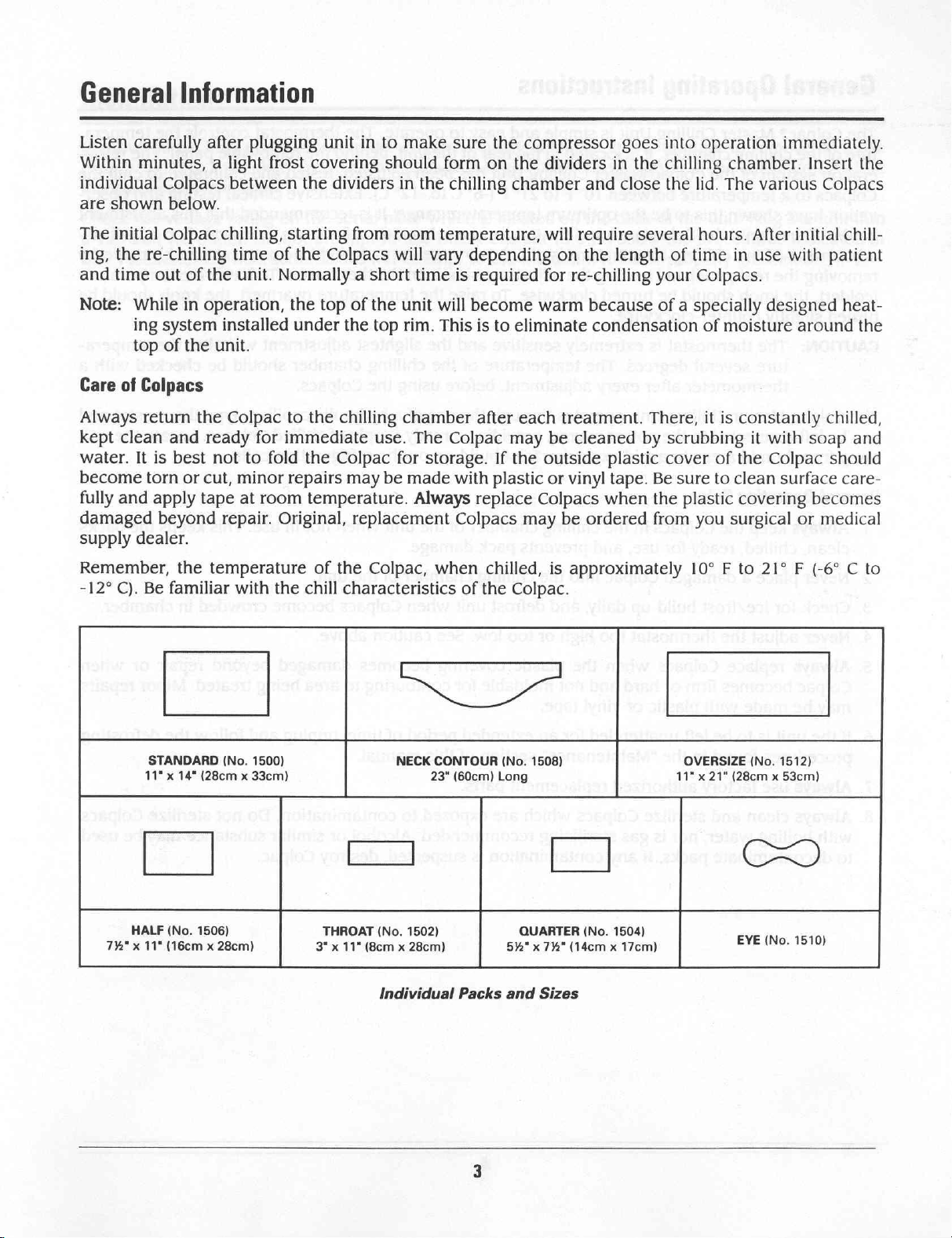
Listen
Within
individual
are
The
ing,
and
carefully
minutes, a light
Colpacs
shown
initial
time
Colpac
the
re-chilling
out
Information
after
plugging
frost
between
below.
chilling,
of
the
time
unit.
starting
of
Normally a short
unit
covering
the
dividers
the
Colpacs
in
to
from
make
should
in
the
room
will
vary
time
sure
the
compressor
form
on
the
chilling
temperature,
is
chamber
depending
required
goes
into
dividers
will
on
for
in
the
chilling
and
close
the
require several hours.
the
length
re-chilling
of
your
operation
chamber.
lid.
The
various
After
time
in
use
Colpacs.
immediately.
Insert
initial
with
the
Colpacs
chill-
patient
Note:
Care
Always
kept
water.
become
fully
damaged
supply
Remember,
-12°
While
ing
top
of
Colpacs
return
clean
It
torn
and
dealer.
C).
Be
STANDARD
11" x 14"
in
system
of
the
the
and
is
best
or
apply
tape
beyond
the
familiar
(28cm x 33cm)
operation,
installed
unit.
Colpac
ready
cut,
for
immediate
not
to
fold
minor
at
room
repair.
temperature
with
Original,
the
(No.
1500)
the
top
of
under
to
repairs
the
the
chilling
the
Colpac
may
temperature.
replacement
of
the
chill
characteristics
the
unit
top
rim.
chamber
use.
The
for
be
made
Always
Colpac,
ED
NECK
will
become
This
is
after
Colpac
storage.
with
replace
Colpacs
when
CONTOUR
23"
chilled,
of
the
(60cm) Long
warm
to
eliminate
each
may
If
the
outside
plastic
or
Colpacs
may
Colpac.
(No.
1508)
because
condensation
treatment.
be
cleaned
plastic
vinyl tape. Be
when
be
ordered
is
approximately
of a specially
of
moisture
There,
by
the
from
it
is
scrubbing
cover
of
sure
to
plastic
you
10° F to
OVERSIZE
11" x 21"
clean
surgical
(28cm x 53cm)
constantly
it
the
covering
(No.
designed
with
Colpac
surface
21° F (-6° C to
heat-
around
chilled,
soap
should
care-
becomes
or
medical
the
and
1512)
HALF
11"
x
7%"
(No.
1506)
x
(16cm
28cm)
THROAT
3"
ss
11"
x
ba]
(No.
1502)
28cm)
x
(8cm
Individual
Packs
QUARTER
x
5%"
and
(14cm
732"
Sizes
(No.
1504)
17cm)
x
CO
(No,
EVE
1510)
Page 6
General
The
Colpac®
ture
of
the
chilling
eration
Colpacs
vation
not
adjustment
removing
(colder),
turned
system
to a temperature
have
be
altered
the
the
slightly
Operating
Master
shown
until
of
rear
knob
Chilling
chamber.
of
the
Colpac
between
this
to
be
the
Colpac
the
chilling
panel
should
counter-clockwise.
temperature
and turning
be
Instructions
Unit
is
It
is
located
Master
the
optimum
unit
turned
simple
Chilling
10° F to
and
the
clockwise.
and
easy
in
the
rear
Unit
21° F (-6° C to
temperature
the
Colpacs
is
absolutely
adjustment
To raise
to
operate.
of
the
unit,
has
been
-12°
range.
have
been
necessary. A slight
knob
on
the
The
behind
adjusted,
C).
Extensive
It
is
used
the
thermostat.
temperature
thermostat
the
removable
tested
recommended
for
and
clinical
some
time,
adjustment
To
(warmer),
controls
the
panel.
calibrated
testing
that
this
and
then only
can
be
lower
the
the
temperature
knob
tempera-
The
refrig-
to
chill
the
and
obser-
adjustment
if
any
made
should
by
be
CAUTION:
The
Colpac
can
be
left
away
from
General
1.
Always
clean,
Never
N
Check
O
Never
Always
AUS
Colpac
may
6.
If
the
procedures
7.
Always
The
thermostat
ture
several
thermometer
Master
connected
humid
Operating
keep
chilled,
place a damaged
for
adjust
replace
becomes
be
made
unit
use
Chilling
areas
Rules
the
Colpacs
ready
ice/frost
the
thermostat
Colpacs
firm
with
is
to
be
found
factory
is
extremely
degrees.
after
every
Unit
to
the
power
to
avoid
in
for
use,
Colpac
build-up
when
or
hard
plastic
left
in
authorized
or
unattended
the
“Maintenance”
sensitive
The
temperature
adjustment,
operates
source,
excessive
the
chilling
and
prevents
into
the
daily,
and
too
high
the
plastic
and
not
vinyl
tape.
for
replacement
and
the
of
the
before
through
providing a ready
frost
build-up
chamber
pack
chilling
defrost
or
too
low.
covering
moldable
an
extended
section
parts.
using
the
use
of
the
damage.
chamber
unit
when
See
for
contouring
period
of
this
slightest
chilling
of a hydraulic
supply
on
the
unit
of
Colpacs
caution
becomes
of
manual.
adjustment
chamber
the
Colpacs.
of
chilled
refrigeration
when
time,
the
unit.
above.
damaged
to
not
become
area
unplug
will
should
capillary
in
being
type
Colpacs.
coils.
use.
This
crowded
beyond
treated.
and
follow
alter
the
be
checked
thermostat
Locate
keeps
in
chamber.
repair
Minor
the
tempera-
with
a
and
the
unit
the
packs
or
when
repairs
defrosting
8.
Always
with
to
clean
boiling
decontaminate
and
water,
packs.
sterilize
nor
Colpacs
is
gas
If
any
which
sterilizing
contamination
recommended.
are
exposed
is
suspected,
to
contamination.
Alcohol
or
similar
destroy
Colpac.
Do
not
sterilize
substance
may
Colpacs
be
used
Page 7

Installation
Remove
pieces
the
of
drain
all
packing
paper
valve
and
is
closed.
material
other
packing
inside
material
the
Colpac®
which
chilling
chamber.
might
otherwise
It
is
important
plug
the
to
drain!
remove
Make
all
loose
certain
that
Check
a
the
the
voltage
120
Volt
“Precautionary
AC
rating
outlet.
Do
Instructions”.
on
not
the
serial
attempt
Do
plate
to
not
which
use
Direct
attempt
is
Current
to
use
located
the
unit
on
the
(D.C.).
if
it
back
Follow
is
not
of
the
unit.
the
procedures
properly
Plug
the
indicated
grounded.
unit into
in
Page 8

Maintenance
Care
of
Unit
The
Colpac®
maintain
ed
to
the
Master
the
proper
electrical
Chilling
Colpac
outlet,
providing a ready
Unit
is
equipped
temperature
with a hydraulic
evenly
supply
in
the
chilling
of
chilled
capillary
chamber.
Colpacs.
type
The
thermostat
unit
may
be
in
order
left
connect-
to
Periodically,
are
crowded
when
Defrosting
Dust
periodically
panel.
this
1.
Disconnect
2.
Raise
warm
3.
Attach
panel.
4.
Open
n
Allow
before
Close
Plug
ea
Clean and
9.
Close
and
Always
occurs
Unit
chamber
water
extension
bottom
unit
the
bottom
unit
chamber
lint
to
the
accumulated
and
insertion
and
the
unit
lid
may
be
drain
drain
to
defrost
unit
is
started
drain
back
into
return
will
insure
disconnect
Colpacs
lid — chilling
accumulate
highest
or
the
inside
from
its
and
remove
poured
hose
valve.
completely.
again.
valve
the
and
power
to
efficiency.
power
frost
in
removal
of
the
power
Colpacs.
over
to
the
detach
source.
the
chilling
sequence
on
the
before
the
chilling
of
the
packs
tank
wiped
source.
Leave
the
refrigeration
valve,
All
condenser
The
cleaning
located
excess
extension
chamber.
begins
condenser
chamber
becomes
dry
with a clean
lid
open
coils
beneath
water
drain
again.
fins
of
the
condenser.
will
build
difficult.
to
speed
to
speed
chilling
must
be
removed
hose.
the
refrigeration
may
be
reached
up
to a point
The
units
should
towel
or
cloth.
defrosting. A small
defrosting.
chamber,
from
unit.
by
removing
behind
the
This
where
be
chilling
must
be
the
the
Colpacs
defrosted
amount
rear
access
chamber
removed
rear
access
of
Replacing
1.
Remove
Remove
do
Remove
a
Remove
a
Remove
a
To
reinstall,
After
ga
ing
nut
Thermostat
plate.
bushing
packing
brass
rubber
installation,
with
nut.
in
nut.
washer.
reverse
seal
silicone
Thermostat
bushing
procedure.
top
of
nut.
pack-
sealant.
Installation
Page 9

Trouble
SYMPTOM
A.
Unit
plugged
packs
not
B.
Packs
too
C.
Packs
too
Shooting
POSSIBLE
in
but
chilled.
cool.
warm.
1.
2.
3.
4.
5.
1.
2.
1.
CAUSE
Breaker
circuit
Thermostat
functioning.
Fan
Compressor
Refrigerant
Thermostat
low.
Thermostat
Thermostat
for
electrical
off.
not
motor
failure. | 3.
failure.
leak.
set
failure.
set
too
too
SUGGESTED
1.
Turn
breaker
2.
Replace
Replace
4.
Contact
5.
Contact
1.
Adjust
Thermostat.
2.
Replace
1.
Adjust
themostat.
SOLUTION
on.
thermostat
motor.
factory.
factory.
Thermostat.
Technical
Type
Amount
Test
Pressures,
Normal
Operating
high.
2.
Thermostat
3.
Power
failure.
failure.
Specifications
Rated
Rated
of
of
Voltage:
Frequency:
Current: 4 Amps
Horsepower:
Refrigerant:
Refrigerant:
All
Models:
Temperature,
All
Models:
115V
60
Hz
1/5
R-134A
C-2,
C-5,
C-6,
High,
Low,
-12°C
+10º F to
2.
3.
11
oz.
11
oz.
12.5
oz.
235
psi
150
psi
to
-6°C
+21°F
Replace
Check
circuit.
thermostat.
electrical
Page 10

Parts
Drawing:
Model
C-2
14
Page 11

Parts
List:
Model
C-2
1
20500
3
20042
4
21282
5
21635
6
21983
7
20514
8
22219
9
22220
10
|‘
21373
11
12
13
14
15
16
17
18
Note:
21259
22121
4228
22409
22420
22955
20237
60286
Whenever
always
of
the
include
unit.
THERMOSTAT,
LAMP,
Pilot
CORD
SET,
HOSE,
BACK
DOOR,
HANDLE,
LID,
Assembly
STOP,
S-C
VALVE,
CASTER,
COMPRESSOR,
THERMOMETER,
COIL
COVER,
COIL
COVER,
COIL
COVER,
HANDLE,
LATCH,
ordering
serial
Resale
Light
w/J28G
Nylon,
5/8" x 12",
Sub-Assembly
Lid,
Resale
3.625" x 16.75"
Boiler
Drain,
3”
EY4520,
13.5" x 22.75",
Sub-Assembly
Middle,
Decorative,
Door,
Rear
parts
number
Coupled,
1/2"
ID,
7/16-20 x 1/2"
BM2A528-1
Dial
Aluminum
12"
(not
shown)
or
corresponding
which
M-F
Chrome
Outside
is
located
一
一
一
一
一
一
一
一
一
睛
一
一
一
一
下
about
on
the
unit,
back
Page 12

Parts
Drawing:
Model
C-5
10
Page 13

Parts
List:
1
3
20042
4
5
6
7
8
9
10
11
12
22121
13
14
15
16
17
18
20500
21282
21635
22457
20514
22297
22300
21373
21259
22461
22462
22956
20237
60286
4228
Model
THERMOSTAT,
LAMP,
Pilot
CORD
SET,
HOSE,
Nylon,
DOOR,
Rear,
HANDLE,
LID,
Assembly
STOP,
S-C
VALVE,
Boiler
CASTER,
COMPRESSOR,
THERMOMETER,
COIL
COVER,
COIL
COVER,
COIL
COVER,
HANDLE,
LATCH,
Door,
C-5
Resale
Light
w/J286
5/8” x 12”,
Complete
Lid,
Resale
3.625" x 16.75"
Drain,
1/2”
3”
EY4520,
Decorative,
7/16-20 x 1/2”
BM2A528-1
Dial
Outside
Sub-Assembly
Middle,
Rear
Aluminum
12”
(not
shown)
Coupled,
ID,
Chrome
M-F
1
1
1
1
1
1
1
1
1
4
1
1
1
1
E
3
À
2
|
1
Note:
Whenever
always
of
the
include
unit.
ordering
serial
parts
number
or
corresponding
which
is
located
about
on
the
nit,
hack
11
Page 14

Parts
Drawing:
Model
C-6
e
9
12
Page 15

Parts
List:
1
20500
3
20042
4
21282
5
21635
6
23008
20514
7
8
22348
9
22352
10
1
12
13
14
15
16
17
18
21373
21260
22121
23021
23022
22954
20237
60286
4228
Model
THERMOSTAT,
LAMP,
Pilot
CORD
SET,
HOSE,
Nylon,
DOOR,
Rear,
HANDLE,
LID,
Assembly
STOP,
S-C
VALVE,
Boiler Drain,
CASTER,
COMPRESSOR,
THERMOMETER,
COIL
COVER,
COIL
COVER,
COIL
COVER,
HANDLE,
LATCH,
Door,
C-6
Resale
Light
w/J28G
5/8" x 12”,
Complete
Lid,
Resale
3.625" x 16.75"
1/2"
3”
EY4520,
Decorative,
7/16-20 x 1/2"
BM2A528-1
Dial
Outside
Sub-Assembly
Middle,
Rear
Aluminum
12”
(not
shown)
Coupled,
ID,
M-F
Chrome
dial
ni
mp
mm
NO
Note:
Whenever
always
of
the
include
unit.
ordering
serial
parts
number
or
corresponding
which
is
located
about
on
the
unit,
back
13
Page 16

Electrical
Schematics:
Models
Compresi
iti
bl
Thermostat
C-2,
IU
C-5,
Heating
一
fic
C-6
나
Element
EL
qi
|
ヒーーーー
lh
14
Page 17

1-800-592-7329
Wellness
CHATTANOOGA
GROUP,
By
INC.
Design®
 Loading...