

Page 1
User Manual
Operation & Installation
Instructions for:
Therapy Systems
2761- Two Channel Combination System
2789- Four Channel Combination System
2764- Two Channel Electrotherapy System
2787- Four Channel Electrotherapy System
2871- Two Channel Electrotherapy System- no sEMG
2872- Two Channel Combination System- no sEMG
2873- Four Channel Electrotherapy System- no sEMG
2874- Four Channel Combination System- no sEMG
2875K- Two Channel Electrotherapy System with Cart- no sEMG
2876K- Two Channel Combination System with Cart- no sEMG
2877K- Four Channel Electrotherapy System with Cart- no sEMG
2878K- Four Channel Combination System with Cart- no sEMG
Optional Equipment
2775- Therapy System Cart (Unassembled)
2775ASY- Therapy System Cart (Assembled)
2767- NiMH Battery Module
2799- Dual Channel sEMG Module
27508 and 27079- User Remote Controls
2781- Channel 3/4 Electrotherapy Module
ISO 13485 CERTIFIED
Page 2
TABLE OF CONTENTS
i
Vectra Genisys® Therapy System
FOREWORD ............................................... 1
PRODUCT DESCRIPTION.....................................1
SAFETY PRECAUTIONS.................................. 2-12
PRECAUTIONARY DEFINITIONS .............................2
Caution ...........................................................2
Warning ..........................................................2
Danger............................................................2
Dangerous Voltage ...............................................2
Corrosive .........................................................2
Spontaneous Combustion .......................................2
Biohazardous Materials ..........................................2
Non-Ionizing Electromagnetic Radiation........................2
CAUTIONS ...................................................3
WARNINGS...................................................4
DANGERS ....................................................6
ELECTROTHERAPY INDICATIONS, CONTRAINDICATIONS,
AND ADVERSE EFFECTS .....................................7
Indications for VMS, VMS Burst, Russian, TENS,
High Voltage Pulsed Current (HVPC), Interferential,
and Premodulated Waveforms ...................................7
Additional Indications for Microcurrent, Interferential,
Premodulated, VMS™, VMS™ Burst, and TENS Waveforms .......7
Indications for DC (Direct Current) Mode ........................7
Contraindications ................................................7
Additional Precautions ...........................................8
Adverse Eects ...................................................8
sEMG INDICATIONS ..........................................9
sEMG + STIM INDICATIONS, CONTRAINDICATIONS
AND ADVERSE EFFECTS ....................................10
Indications- sEMG + Stim using VMS™, Symmetrical Biphasic
(TENS), Asymmetrical Biphasic (TENS), or Russian waveforms .10
Contraindications ...............................................10
Additional Precautions ..........................................11
Adverse Eects ..................................................11
ULTRASOUND INDICATIONS AND CONTRAINDICATIONS ..12
Indications for Ultrasound ......................................12
Contraindications ...............................................12
Additional Precautions ..........................................12
NOMENCLATURE ......................................13-17
VECTRA GENISYS ELECTROTHERAPY AND
COMBINATION THERAPY SYSTEMS.........................13
Two Channel Electrotherapy System............................13
Two Channel Combination System..............................13
Front Access Panel...............................................14
Rear Access Panel................................................14
USER INTERFACE............................................15
SYMBOL DEFINITIONS......................................16
System Hardware Symbols......................................16
System Software Symbols.......................................16
Optional Module and Accessory Symbols ......................16
Operator Remote................................................16
Battery Module ..................................................16
Channel 3/4 Electrothrapy Module .............................16
GENERAL TERMINOLOGY ...................................17
Back Button......................................................17
Previous Page Button ...........................................17
UP and DOWN Arrows...........................................17
Electrotherapy...................................................17
Page 3
TABLE OF CONTENTS
ii
Vectra Genisys® Therapy System
System ...........................................................17
Module ..........................................................17
sEMG.............................................................17
sEMG + Stim .....................................................17
ULTRASOUND ...............................................17
Sound Head .....................................................17
Applicator .......................................................17
Coupling LED ....................................................17
SPECIFICATIONS ......................................18-24
SYSTEM SPECIFICATIONS AND DIMENSIONS ..............18
DESCRIPTION OF DEVICE MARKINGS ......................18
WAVEFORM SPECIFICATIONS ..............................19
IFC - Interferential (Traditional 4 Pole) ..........................19
TENS- Asymmetrical Biphasic ...................................19
TENS- Symmetrical Biphasic.....................................20
Microcurrent.....................................................20
IFC Premodulated (Traditional 2 Pole IFC) ......................21
High Voltage Pulsed Current (HVPC) ............................21
VMS
™ ............................................................22
VMS™ Burst ......................................................22
Russian ..........................................................23
DC (Direct Current) ..............................................23
ULTRASOUND SPECIFICATIONS ............................24
Ultrasound.......................................................24
Ouput Power ....................................................24
Head Warming Feature..........................................24
SET UP ................................................25-31
VECTRA GENISYS THERAPY SYSTEMS......................25
THERAPY SYSTEM SET UP ..................................26
Accessing Operator Utilities.................................26
Clinic Name......................................................26
Restore Default Protocols .......................................27
Restore Default Unit Settings ...................................27
Erase Patient Data Card .........................................28
Set Date and Time . . . . . . . . . . . . . . . . . . . . . . . . . . . . . . . . . . . . . . . . . . . . . . .28
Setting System Volume..........................................29
Ultrasound Coupling ............................................29
Display Unit Version Information ...............................30
Pad Contact Quality .............................................30
Select Language.................................................31
Connecting Accessories to the Therapy System ................31
PATIENT PREPARATION ................................32-40
ELECTROTHERAPY PATIENT PREPARATION ................32
Electrode Placement ............................................32
DURA-STICK™ Electrodes........................................33
Reusable Carbon Electrodes (Optional).........................33
DURA-STICK™ Electrode Instructions ...........................34
Connecting Lead Wires ..........................................34
Securing Electrodes .............................................34
Reusable Carbon Electrodes (Optional).........................35
Connecting Lead Wires ..........................................35
Conductive Medium.............................................35
Securing Electrodes .............................................35
ULTRASOUND PATIENT PREPARATION .....................36
Preparing Treatment Area.......................................36
Size of Applicator................................................36
Page 4
TABLE OF CONTENTS
iii
Vectra Genisys® Therapy System
Applicator Preparation ..........................................36
Conductive Medium.............................................36
Treatment Area ..................................................36
Applicator Coupling.............................................36
sEMG AND sEMG+STIM PATIENT PREPARATION .......... 37
Install sEMG Lead Wires to System ..............................37
Install DURA-STICK™ II Electrodes...............................37
Select Modality ..................................................37
Select Body Area ................................................38
View Electrode Placement Graphic..............................38
View Electrode Placement Text..................................39
Prepare Treatment Area .........................................39
Electrode Placement ............................................40
Intra-Vaginal Probe ..............................................40
OPERATION ..........................................41-114
OPERATOR INTERFACE......................................41
HOME SCREEN ..............................................42
ELECTROTHERAPY SCREEN.................................43
GENERAL ELECTROTHERAPY WAVEFORM SET UP..........44
Prepare Patient..................................................44
Select Modality ..................................................44
Select Waveform.................................................44
View Waveform Description.....................................44
View Electrode Placement.......................................45
Edit Waveform Parameters ......................................45
Install Optional Patient Interrupt Switch .......................45
Optional Patient Interrupt Switch ..............................46
Set Waveform Intensity..........................................46
Intensity Knob Rotation .........................................46
Start Treatment ..................................................46
Pause Treatment.................................................47
Stop Treatment ..................................................47
Save to Patient Data Card .......................................47
ADJUSTING ELECTROTHERAPY CHANNEL
PARAMETERS DURING TREATMENT ........................48
Select Channel...................................................48
Edit Channel Paramenters.......................................48
ULTRASOUND ...............................................49
Prepare Patient..................................................49
Select Modality ..................................................49
View Parameter Rationale.......................................49
Sound Head Recommendation .................................49
Edit Ultrasound Parameters.....................................50
Head Warming...................................................50
Set Ultrasound Intensity ........................................50
Intensity Knob Rotation .........................................50
Start Treatment ..................................................51
Pause Treatment.................................................51
Stop Treatment ..................................................51
Save to Patient Data Card .......................................51
ADJUSTING ULTRASOUND PARAMETERS
DURING TREATMENT .......................................52
Editing Ultrasound from Home Screen..........................52
Editing Ultrasound from Treatment Review Screen.............52
sEMG THERAPY SET UP .....................................53
General Information.............................................53
Optional Patient Data Management System (PDMS) ...........53
Page 5

TABLE OF CONTENTS
iv
Vectra Genisys® Therapy System
sEMG Screen.....................................................54
Prepare System and Patient .....................................55
Select sEMG Modality ...........................................55
View sEMG Description Text.....................................55
Electrode Placement ............................................55
Select Edit .......................................................56
Select Channel...................................................56
Set Alarm ........................................................56
Set Audio Type...................................................57
Select Target Option.............................................57
Setting Max Target ..............................................57
Setting Avg Target...............................................58
Setting Manual Target ...........................................59
Set Volume ......................................................59
Start sEMG Therapy Session.....................................60
Stopping sEMG Therapy Session ................................60
INDICATIONS ...............................................61
Available Indications ............................................61
Prepare Patient..................................................61
Select Indication.................................................61
View Waveform Description.....................................61
View Electrode Placement.......................................62
Edit Waveform Parameters ......................................62
Install Optional Patient Interrupt Switch .......................62
Optional Patient Interrupt Switch ..............................63
Setting Waveform Intensity .....................................63
Intensity Knob Rotation .........................................63
Start Treatment ..................................................64
Pause Treatment.................................................64
Stop Treatment ..................................................64
Editing Parameters during Treatment Session..................65
Save to Patient Data Card .......................................65
COMBINATION ..............................................66
Prepare Patient..................................................66
Select Modality ..................................................66
View Application Description ...................................66
View Electrode Placement.......................................67
Access Combination Parameters ................................67
Edit Ultrasound Parameters.....................................67
Select Waveform.................................................68
Optional Patient Interrupt Switch ..............................68
Edit Waveform Parameters ......................................68
Set Waveform Intensity..........................................69
Intensity Knob Rotation .........................................69
Set Ultrasound Intensity ........................................69
Intensity Knob Rotation .........................................69
Start Treatment ..................................................69
Pause Treatment.................................................70
Stop Treatment ..................................................70
Save to Patient Data Card .......................................70
ADJUSTING COMBINATION PARAMETERS
DURING TREATMENT .......................................71
Edit Waveform Parameters ......................................71
Edit Ultrasound Parameters.....................................71
sEMG+STIM THERAPY SET UP ..............................72
General Information.............................................72
Page 6
TABLE OF CONTENTS
v
Vectra Genisys® Therapy System
Prepare System and Patient .....................................73
Select sEMG + Stim Modality....................................73
Select Edit .......................................................73
Select Channel...................................................73
Set Alarm ........................................................74
Set Audio Type...................................................74
Select Stim Waveform . . . . . . . . . . . . . . . . . . . . . . . . . . . . . . . . . . . . . . . . . . .74
Edit Stim .........................................................75
Select Target Option.............................................75
Setting Max Target ..............................................75
Setting Avg Target...............................................76
Setting Manual Target ...........................................77
Set Volume ......................................................77
Set Auto Feature.................................................78
Start sEMG Therapy Session.....................................78
Stopping Stim ...................................................79
Stopping Therapy Session.......................................79
PATIENT DATA CARD SET UP OF NEW CARD ...............80
General Information.............................................80
Insert New Patient Data Card ...................................80
Setup Treatment.................................................80
Set Up of New Patient Data Card ...............................80
Enter Patient ID..................................................81
Access Electrode Placement.....................................82
Electrode Placement Set Up.....................................82
Electrode Placement ............................................82
Access Pain Map.................................................83
Select Pain Type .................................................83
Add Pain Locations ..............................................83
Select Location of Pain ..........................................84
Editing Pain Locations...........................................84
Deleting Pain Locations .........................................85
Pain Scales.......................................................85
Select Pain Scale.................................................85
Adjust Pain Scale ................................................85
Save to Patient Data Card .......................................86
EXISTING PATIENT DATA CARD USE ........................87
Insert Existing Patient Data Card................................87
Access Patient Data Card ........................................87
View Patient Data Card ..........................................87
Starting a New Treatment from Patient Data Card..............88
Optional Patient Interrupt Switch...............................88
Set Intensity .....................................................88
Intensity Knob Rotation .........................................88
Start Treatment ..................................................89
Pause Treatment.................................................89
Stop Treatment ..................................................89
Erasing Patient Data Card .......................................89
SET UP OF NEW sEMG DATA CARD ..........................90
General Information.............................................90
Insert New sEMG Data Card .....................................91
Prepare System and Patient .....................................91
Set Up sEMG Therapy Session...................................91
Enter Patient ID..................................................91
Begin Save.......................................................92
End Save.........................................................92
Page 7
TABLE OF CONTENTS
vi
Vectra Genisys® Therapy System
CLINICAL RESOURCES LIBRARY CLINICAL PROTOCOLS™ ....93
Clinical Protocols™...............................................93
Access Clinical Resources........................................93
Access Clinical Protocols™.......................................93
Select Body Area ................................................93
Select Clinical Indication ........................................94
Select Pathological Condition...................................94
Select Pathological Severity.....................................94
View Waveform Rationale .......................................95
View Electrode Placement.......................................95
Prepare Patient..................................................95
Edit Modality Parameters .......................................95
Optional Patient Interrupt Switch ..............................96
Set Modality Intensity ...........................................96
Intensity Knob Rotation .........................................96
Start Treatment ..................................................97
Pause Treatment.................................................97
Stop Treatment ..................................................97
Save to Patient Data Card .......................................97
CLINICAL RESOURCES LIBRARY
CREATING USER PROTOCOLS...............................98
General Information.............................................98
Select Modality ..................................................98
Edit Modality Parameters .......................................98
Select Clinical Resources Library ................................98
Enter User Protocol Name.......................................99
CLINICAL RESOURCES LIBRARY
DELETING USER PROTOCOLS ..............................100
General Information........................................... 100
Select Clinical Resources Library .............................. 100
Select User Protocol to Delete................................. 100
Delete User Protocol...........................................100
CLINICAL RESOURCES LIBRARY
USING USER PROTOCOLS ..................................101
Access User Protocols ......................................... 101
Select User Protocol ...........................................101
View Waveform Rationale ..................................... 101
View Electrode Placement..................................... 102
Prepare Patient................................................ 102
Edit Modality Parameters ..................................... 102
Optional Patient Interrupt Switch ............................ 102
Set Modality Intensity .........................................103
Intensity Knob Rotation .......................................103
Start Treatment ................................................103
Pause Treatment............................................... 104
Stop Treatment ................................................ 104
Save to Patient Data Card ..................................... 104
CLINICAL RESOURCES LIBRARY
CREATING NEW SEQUENCES...............................105
General Information........................................... 105
Access Sequencing ............................................ 105
Select Sequence ...............................................105
Select First Waveform or Current.............................. 105
Edit First Waveform or Current ................................ 106
Select Second Waveform or Current .......................... 106
Saving New Sequence......................................... 106
Enter Sequence Name......................................... 107
Page 8
TABLE OF CONTENTS
vii
Vectra Genisys® Therapy System
CLINICAL RESOURCES LIBRARY
DELETING SEQUENCES ....................................108
General Information........................................... 108
Access Sequencing ............................................ 108
Select Sequence ...............................................108
Delete Sequence .............................................. 108
CLINICAL RESOURCES LIBRARY
USING SEQUENCES ........................................109
Access Sequencing ............................................ 109
Select Sequence ...............................................109
Select Waveform/Current .....................................109
View Waveform Rationale ..................................... 110
View Electrode Placement..................................... 110
Prepare Patient................................................ 110
Optional Patient Interrupt Switch ............................ 110
Set Sequence Intensity ........................................111
Intensity Knob Rotation .......................................111
Start Treatment ................................................112
Pause Treatment............................................... 112
Stop Treatment ................................................ 112
Save to Patient Data Card ..................................... 112
CLINICAL RESOURCES LIBRARY
MMC GRAPHICAL LIBRARY ................................113
General Information........................................... 113
Select Clinical Resources Library .............................. 113
Select MMC Graphical Library................................. 113
Select Body Area .............................................. 113
Select Library Type ............................................ 114
INSTALLATION/REMOVAL ............................115-133
INSTALLATION CHANNEL 3/4 ELECTROTHERAPY,
NiMH BATTERY, AND LASER MODULE .....................115
Possible System Congurations ............................... 115
Nomenclature- Channel 3/4 Electrotherapy Module ......... 116
Specications.................................................. 117
Waveform & Current Specications . . . . . . . . . . . . . . . . . . . . . . . . . . . 117
Disconnect Mains Power ...................................... 118
Remove Lead Wires and Accessories .......................... 118
Remove Therapy System from Cart ........................... 118
Release Ribbon Cable ......................................... 119
Position Therapy System and Module......................... 119
Connect Ribbon Cable......................................... 119
Set Therapy System onto Module ............................120
Secure Therapy System to Module ...........................120
Front Access Panel ............................................ 120
Install Lead Wires and Accessories ............................ 121
Install Front Access Panel ..................................... 121
Mount to Therapy System Cart ................................ 121
Connect Mains Power ......................................... 121
Turn Therapy System On ...................................... 122
REMOVAL CHANNEL 3/4 ELECTROTHERAPY,
NiMH BATTERY, AND LASER MODULE .....................123
Disconnect Mains Power ...................................... 123
Remove Lead Wires and Accessories .......................... 123
Remove Therapy System from Cart ........................... 123
Remove Screws Securing Module ............................ 124
Disconnect Ribbon Cable at Module ..........................124
Store and Secure Ribbon Cable ............................... 124
Front Access Panel ............................................ 125
Page 9
TABLE OF CONTENTS
viii
Vectra Genisys® Therapy System
Install Lead Wires and Accessories ............................ 125
Connect Mains Power ......................................... 125
Turn Therapy System On ...................................... 126
INSTALLING
sEMG MODULE ...............................127
Position sEMG Module ........................................ 127
Secure sEMG Module .......................................... 127
Install and Reinstall Additional Module....................... 127
Install Rear Access Panel ...................................... 127
Install Cables and Accessories................................. 128
Apply Mains Power............................................ 128
REMOVING
sEMG MODULE ................................129
Prepare System................................................ 129
Remove sEMG Module ........................................ 129
sEMG Plug Kit.................................................. 129
GENERAL INFORMATION OPERATOR REMOTE ...........130
Operator Remote Installation . . . . . . . . . . . . . . . . . . . . . . . . . . . . . . . . . 130
GENERAL INFORMATION THERAPY SYSTEM CART .......131
Nomenclature ................................................. 131
Specications.................................................. 131
MOUNTING THERAPY SYSTEM TO
THERAPY SYSTEM CART ...................................132
Therapy System Cart Assembly ............................... 132
Prepare Therapy System Cart .................................132
Mount Therapy System to Cart ................................ 132
Connect Mains Power ......................................... 133
Install Storage Bins ............................................133
Removing System from Therapy System Cart ................ 133
OPTION OPERATION .................................134-139
OPERATOR REMOTE OPERATION ..........................134
Nomenclature ................................................. 134
Operation...................................................... 134
Operator Remote Storage..................................... 135
THERAPY SYSTEM CART OPERATION......................136
Nomenclature ................................................. 136
Operation...................................................... 136
NiMH BATTERY MODULE OPERATION . . . . . . . . . . . . . . . . . . . . .137
Nomenclature ................................................. 137
CHARGING BATTERY MODULE.............................138
When to Recharge............................................. 138
Charging Temperature ........................................ 138
BATTERY MODULE SERVICE LIFE ..........................139
STORAGE OF BATTERY MODULE...........................139
Short Term Storage ............................................139
Long Term Storage ............................................ 139
TROUBLESHOOTING.................................140-145
ERROR CODES.........................................140-145
General Information........................................... 140
REPLACEMENT ACCESSORIES ............................146
GENERAL INFORMATION ..................................146
MAINTENANCE ..........................................147
CARING FOR THE THERAPY SYSTEM.......................147
Cleaning the Therapy System ................................. 147
Cleaning the Lens ............................................. 147
CALIBRATION REQUIREMENTS ............................147
Calibrating Ultrasound Applicators ...........................147
FACTORY SERVICE .........................................147
WARRANTY .............................................148
Page 10

Vectra Genisys® Therapy System
FOREWORD
1
This manual has been written for the users of the Vectra Genisys® Therapy Systems. It contains general information on the operation,
precautionary practices, and maintenance information. In order to maximize use, efficiency, and the life of the system, please read this
manual thoroughly and become familiar with the controls, as well as the accessories before operating the system.
This manual contains general safety, operating, maintenance, and care instructions as well as installation instructions for the optional
Therapy System Cart, Channel 3/4 Electrotherapy, NiMH Battery, Laser and Dual Channel sEMG Modules for the users of the Vectra Genisys
Therapy two channel electrotherapy and combination systems.
Specifications put forth in this manual were in effect at the time of publication. However, owing to DJO, LLC's policy of continual
improvement, changes to these specifications may be made at any time without obligation on the part of DJO, LLC.
Before administering any treatment to a patient, the users of this equipment should read, understand and follow the information
contained in this manual for each mode of treatment available, as well as the indications, contraindications, warnings and precautions.
Consult other resources for additional information regarding the application of electrotherapy and ultrasound.
PRODUCT DESCRIPTION
The Vectra Genisys Therapy Systems are two channel electrotherapy and combination systems with the option of adding additional
channels of electrotherapy by installation of the optional Channel 3/4 Electrotherapy Module. Other optional modality modules are
available for separate purchase and may be installed by the end user.
Stay current with the latest clinical developments in the field of electrotherapy, ultrasound, laser therapy, sEMG and sEMG + Stim. Observe
all applicable precautionary measures for treatment.
Keep informed of appropriate indications and contraindications for the use of electrotherapy, ultrasound, sEMG and sEMG+Stim.
This equipment is to be used only under the prescription and supervision of a licensed practitioner.
©2009 DJO, LLC Vista, California, USA. Any use of editorial, pictorial, or layout composition of this publication without express written consent from DJO, LLC is strictly prohibited. This publication was written, illustrated, and prepared
for distribution by DJO, LLC.
Page 11
Vectra Genisys® Therapy System
SAFETY PRECAUTIONS
2
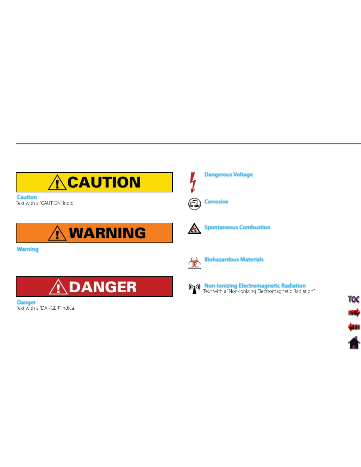
The precautionary instructions found in this section and throughout this manual are indicated by specific symbols. Understand these
symbols and their definitions before operating this equipment. The definition of these symbols are as follows:
Text with a “CAUTION” indicator will explain possible safety infractions that
could have the potential to cause minor to moderate injury or damage to
equipment.
Text with a “WARNING” indicator will explain possible safety infractions that
will potentially cause serious injury and equipment damage.
Text with a “Dangerous Voltage” indicator serves to inform the user
of possible hazards resulting in the electrical charge delivered to
the patient in certain treatment configurations of TENS waveforms.
NOTE: Throughout this manual, “NOTE” may be found. These Notes are
helpful information to aid in the particular area or function
being described.
PRECAUTIONARY DEFINITIONS
Caution
Warning
Dangerous Voltage
Text with a “DANGER” indicator will explain possible safety infractions that
are imminently hazardous situations that would result in death or serious
injury.
Danger
Corrosive
Text with a “Corrosive" indicator will explain possible safety
infractions if the chemical components of the battery are exposed
to air, skin or other materials.
Spontaneous Combustion
Text with a “Spontaneous Combustion" indicator will explain
possible safety infractions that could create conditions for a
spontaneous combustion if the material is mishandled and not
disposed of properly.
Text with a “Biohazard” indicator serves to inform the user of
possible hazards resulting in improper handling of components
and accessories that have come in contact with bodily fluids.
Biohazardous Materials
Text with a “Non-Ionizing Electromagnetic Radiation" indicator
informs the user of possible hazards resulting from elevated,
potentially dangerous, levels of non-ionizing radiation.
Non-Ionizing Electromagnetic Radiation
Page 12
Vectra Genisys® Therapy System
SAFETY PRECAUTIONS
3
Read, understand, and practice the precautionary and operating •
instructions. Know the limitations and hazards associated with
using any electrical stimulation or ultrasound device. Observe the
precautionary and operational decals placed on the unit.
DO NOT operate this unit in an environment where other devices
•
are being used that intentionally radiate electromagnetic energy in
an unshielded manner.
Ultrasound should be routinely checked before each use to
•
determine that all controls function normally, especially that
the intensity control does properly adjust the intensity of the
ultrasonic power output in a stable manner. Also, determine that
the treatment time control does actually terminate ultrasonic power
output when the timer reaches zero.
DO NOT use sharp objects such as a pencil point or ballpoint pen to
•
operate the buttons on the control panel.
This unit should be operated, transported and stored in
•
temperatures between 59° F and 104° F (15° C and 40° C), with
Relative Humidity ranging from 30%-60%.
Handle Ultrasound Applicator with care. Inappropriate handling of
•
the Ultrasound Applicator may adversely affect its characteristics.
Before each use, inspect Ultrasound Applicator for cracks, which
•
may allow the ingress of conductive fluid.
Inspect Applicator cables and associated connectors before •
each use.
The Vectra Genisys Therapy System is not designed to prevent the
•
ingress of water or liquids. Ingress of water or liquids could cause
malfunction of internal components of the system and therefore
create a risk of injury to the patient.
This equipment generates, uses and can radiate radio frequency
•
energy and, if not installed and used in accordance with the
instructions, may cause harmful interference to other devices in
the vicinity. However, there is no guarantee that interference will
not occur in a particular installation. Harmful interference to other
devices can be determined by turning this equipment on and off.
Try to correct the interference using one or more of the following:
reorient or relocate the receiving device, increase the separation
between the equipment, connect the equipment to an outlet on a
different circuit from that to which the other device(s) are connected
and consult the factory field service technician for help.
Nylatex® Wraps contain dry natural rubber and may cause allergic
•
reactions in patients with allergies to latex.
Use of parts or materials other than Chattanooga's can degrade
•
minimum safety.
Page 13

Vectra Genisys® Therapy System
SAFETY PRECAUTIONS
4
U.S.A. Federal Law restricts these devices to sale by, or on the order •
of, a physician or licensed practitioner. This device should be used
only under the continued supervision of a physician or licensed
practitioner.
Make certain the unit is electrically grounded by connecting only to a
•
grounded electrical service receptacle conforming to the applicable
national and local electrical codes.
Care must be taken when operating this equipment around other
•
equipment. Potential electromagnetic or other interference could
occur to this or to the other equipment. Try to minimize this
interference by not using other equipment in conjunction with it.
The safety of TENS waveforms for use during pregnancy or birth has
•
not been established.
TENS is not effective for pain of central origin. (This includes
•
headache.)
TENS should be used only under the continued supervision of a
•
physician or licensed practitioner.
TENS waveforms have no curative value.
•
TENS is a symptomatic treatment, and as such, suppresses the •
sensation of pain which would otherwise serve as a protective
mechanism.
The user must keep the device out of the reach of children.
•
Electronic monitoring equipment (such as ECG monitors and ECG •
alarms) may not operate properly when TENS stimulation is in use.
Powered muscle stimulators should be used only with the leads and •
electrodes recommended for use by the manufacturer.
In the event that an Error message or Warning appears beginning
•
with a 2 or 3, immediately stop all use of the system and contact the
dealer or DJO, LLC for service. Errors and Warnings in these categories
indicate an internal problem with the system that must be tested by
DJO, LLC or a Field Service Technician certified by DJO, LLC before any
further operation or use of the system. Use of a system that indicates
an Error or Warning in these categories may pose a risk of injury to
the patient, user or cause extensive internal damage to the system.
Use of controls or adjustments or performance of procedures other
•
than those specified herein may result in hazardous exposure to
ultrasonic energy.
Before administering any treatment to a patient you should become
•
acquainted with the operating procedures for each mode of
treatment available, as well as the indications, contraindications,
warnings and precautions. Consult other resources for additional
information regarding the application of Electrotherapy and
Ultrasound.
To prevent electrical shock, disconnect the unit from the power
•
source before attempting any maintenance procedures.
Keep electrodes separated during treatment. Electrodes in contact
•
with each other could result in improper stimulation or skin burns.
Long term effects of chronic electrical stimulation are unknown.
•
Page 14
Vectra Genisys® Therapy System
SAFETY PRECAUTIONS
5
Stimulation should not be applied over the anterior neck or mouth. •
Severe spasm of the laryngeal and pharyngeal muscles may occur
and the contractions may be strong enough to close the airway or
cause difficulty in breathing.
Stimulation should not be applied transthoracically in that the
•
introduction of electrical current into the heart may cause cardiac
arrhythmia.
Stimulation should not be applied over swollen, infected, and
•
inflamed areas or skin eruptions, e.g., phlebitis, thrombophlebitis,
varicose veins, etc.
Stimulation should not be applied over, or in proximity to, cancerous
•
lesions.
Output current density is related to electrode size. Improper
•
application may result in patient injury. If any question arises as to
the proper electrode size, consult a licensed practitioner prior to
therapy session.
The Vectra Genisys Therapy System optional modules and associated
•
accessories are designed for use only with the Chattanooga Vectra
Genisys Electrotherapy and Combination Therapy Systems.
Remove the Ultrasound or Laser Applicator by pulling the cable
•
connector only. DO NOT remove by pulling the cable.
Page 15

Vectra Genisys® Therapy System
SAFETY PRECAUTIONS
6
Stimulus delivered by the TENS waveforms of this •
device, in certain configurations, will deliver a charge of
25 microcoulombs (µC) or greater per pulse and may be
sufficient to cause electrocution. Electrical current of this
magnitude must not flow through the thorax because it
may cause a cardiac arrhythmia.
Patients with an implanted neurostimulation device
•
must not be treated with or be in close proximity to
any shortwave diathermy, microwave diathermy,
therapeutic ultrasound diathermy or laser diathermy
anywhere on their body. Energy from diathermy
(shortwave, microwave, ultrasound and laser) can be
transferred through the implanted neurostimulation
system, can cause tissue damage, and can result in
severe injury or death. Injury, damage or death can
occur during diathermy therapy even if the implanted
neurostimulation system is turned “off.”
Handle, clean and dispose of components and accessories
•
that have come in contact with bodily fluids according
to National, Local and Facility rules, regulations and
procedures.
NiMH Batteries contain Class E Corrosive materials. In the •
event of battery cell rupture or leakage, handle Battery
Module wearing neoprene or natural rubber gloves. Contents
of a ruptured or leaking battery can cause respiratory
irritation. Hypersensitivity to nickel can cause allergic
pulmonary asthma. Contents of cell coming in contact with
skin can cause skin irritation and/or chemical burns.
Never, under any circumstances, open the Battery Module •
housing or cells. Should an individual cell from a battery
become disassembled, spontaneous combustion of the
negative electrode is possible. There can be a delay between
exposure to air and spontaneous combustion.
Charge the Battery Module according to the instructions •
found in this manual. Never attempt to charge the Battery
Module on any other charging mechanism.
Use the Battery Module only with the Vectra Genisys Therapy •
Systems.
Do not reverse the polarity of the Battery Module. Doing so •
can increase the individual cell temperature and cause cell
rupture or leakage.
Never dispose of Battery Module in fire. Never short circuit •
the battery. The battery may explode, ignite, leak or get hot
causing serious personal injury.
Dispose of NiMH batteries according to national, state and •
local codes and regulations.
Page 16

Vectra Genisys® Therapy System
SAFETY PRECAUTIONS
7
ELECTROTHERAPY INDICATIONS, CONTRAINDICATIONS, AND ADVERSE EFFECTS
Indications for VMS, VMS Burst, Russian, TENS, High Voltage
Pulsed Current (HVPC), Interferential, and Premodulated
Waveforms
Relaxation of muscle spasms
•
Prevention or retardation of disuse atrophy•
Increase local blood circulation•
Muscle re-education•
Maintaining or increasing range of motion•
Additional Indications for Microcurrent, Interferential,
Premodulated, VMS™, VMS™ Burst, and TENS Waveforms
Symptomatic relief and management of chronic, intractable •
pain
Post-traumatic acute pain•
Post-surgical acute pain•
Indications for DC (Direct Current) Mode
Relaxation of muscle spasm•
Contraindications
This device should not be used for symptomatic local pain relief •
unless etiology is established or unless a pain syndrome has
been diagnosed.
This device should not be used when cancerous lesions are •
present in the treatment area.
Stimulation should not be applied over swollen, •
infected, inflamed areas or skin eruptions (e.g. phlebitis,
thrombophlebitis, varicose veins, etc.).
Other contraindications are patients suspected of carrying •
serious infectious disease and or disease where it is advisable,
for general medical purposes, to suppress heat or fevers.
Electrode placements must be avoided that apply current •
to the carotid sinus region (anterior neck) or transcerebrally
(through the head).
Safety has not been established for the use of therapeutic •
electrical stimulation during pregnancy.
Powered muscle stimulators should not be used on patients •
with cardiac demand pacemakers.
There should not be any use of TENS waveforms on patients •
with cardiac demand pacemakers.
Page 17

Vectra Genisys® Therapy System
SAFETY PRECAUTIONS
8
ELECTROTHERAPY INDICATIONS, CONTRAINDICATIONS, AND ADVERSE EFFECTS (CONTINUED)
Additional Precautions
Caution should be used for patients with suspected or
•
diagnosed heart problems.
Caution should be used for patients with suspected or •
diagnosed epilepsy.
Caution should be used in the presence of the following: •
When there is a tendency to hemorrhage following acute •
trauma or fracture.
Following recent surgical procedures when muscle •
contraction may disrupt the healing process.
Over a menstruating or pregnant uterus.•
Over areas of the skin which lack normal sensation.•
Some patients may experience skin irritation or hypersensitivity •
due to the electrical stimulation or electrical conductive
medium. The irritation can usually be reduced by using an
alternative conductive medium or an alternative electrode
placement.
Electrode placement and stimulation settings should be based •
on the guidance of the prescribing practitioner.
Powered muscle stimulators should be used only with the •
lead wires and electrodes recommended for use by the
manufacturer.
With TENS waveforms, isolated cases of skin irritation may •
occur at the site of electrode placement following long-term
application.
The effectiveness of TENS waveforms is highly dependent upon •
patient selection by a person qualified in pain management.
Adverse Effects
Skin irritation and burns beneath the electrodes have been •
reported with the use of powered muscle stimulators.
Potential adverse effects with TENS are skin irritation and •
electrode burns.
Page 18
Vectra Genisys® Therapy System
SAFETY PRECAUTIONS
9
sEMG INDICATIONS
To determine the activation timing of muscles for:
Retraining of muscle activation
•
Coordination of muscle activation•
An indication of the force produced by muscle for control •
and maintenance of muscle contractions
Relaxation muscle training•
Muscle re-education•
Indications- Surface EMG
Page 19
Vectra Genisys® Therapy System
SAFETY PRECAUTIONS
10
sEMG + STIM INDICATIONS, CONTRAINDICATIONS AND ADVERSE EFFECTS
Stroke rehab by muscle re-education
•
Relaxation of muscle spasms•
Prevention or retardation of disuse atrophy•
Increase local blood circulation•
Muscle re-education•
Maintaining or increasing range of motion•
Indications- sEMG + Stim using VMS™, Symmetrical Biphasic
(TENS), Asymmetrical Biphasic (TENS), or Russian waveforms
Contraindications
This device should not be used for symptomatic local pain
•
relief unless etiology is established or unless a pain syndrome
has been diagnosed.
This device should not be used when cancerous lesions are •
present in the treatment area.
Stimulation should not be applied over swollen, •
infected, inflamed areas, or skin eruptions (e.g. phlebitis,
thrombophlebitis, varicose veins, etc.).
Other contraindications are patients suspected of carrying •
serious infectious disease and/or disease where it is advisable,
for general medical purposes, to suppress heat or fevers.
Electrode placements must be avoided that apply current •
to the carotid sinus region (anterior neck) or transcereberally
(through the head).
Safety has not been established for the use of therapeutic •
electrical stimulation during pregnancy.
Powered muscle stimulators should not be used on patients •
with cardiac demand pacemakers.
There should not be any use of TENS waveforms on patients •
with cardiac demand pacemakers.
Page 20
Vectra Genisys® Therapy System
SAFETY PRECAUTIONS
11
sEMG + STIM INDICATIONS, CONTRAINDICATIONS AND ADVERSE EFFECTS (CONTINUED)
Caution should be used for patients with suspected or diagnosed
•
heart problems.
Caution should be used for patients with suspected or diagnosed •
epilepsy.
Caution should be used in the presence of the following: •
When there is a tendency to hemorrhage following acute •
trauma or fracture.
Following recent surgical procedures when muscle •
contraction may disrupt the healing process.
Over a menstruating or pregnant uterus.•
Over areas of the skin which lack normal sensation.•
Some patients may experience skin irritation or hypersensitivity •
due to the electrical stimulation or electrical conductive medium.
The irritation can usually be reduced by using an alternative
conductive medium or an alternative electrode placement.
Electrode placement and stimulation settings should be based on •
the guidance of the prescribing practitioner.
Powered muscle stimulators should be used only with the lead •
wires and electrodes recommended for use by the manufacturer.
With TENS waveforms, isolated cases of skin irritation may occur at •
the site of electrode placement following long term application.
The effectiveness of TENS waveforms is highly dependent upon •
patient selection by a person qualified in the management of
pain patients.
Additional Precautions
Skin irritation and burns beneath the electrodes have been
•
reported with the use of powered muscle stimulators.
Potential adverse effects with TENS are skin irritation and •
electrode burns.
Adverse Effects
Page 21

Vectra Genisys® Therapy System
SAFETY PRECAUTIONS
12
Indications for Ultrasound
Application of therapeutic deep heat for the treatment of selected
sub-chronic and chronic medical conditions such as:
Relief of pain, muscle spasms and joint contractures•
Relief of pain, muscle spasms and joint contractures that may •
be associated with:
Adhesive capsulitis•
Bursitis with slight calcification•
Myositis•
Soft tissue injuries•
Shortened tendons due to past injuries and scar tissues•
Relief of sub-chronic, chronic pain and joint contractures •
resulting from:
Capsular tightness•
Capsular scarring•
Contraindications
This device should not be used for symptomatic local pain relief •
unless etiology is established or unless a pain syndrome has
been diagnosed.
This device should not be used when cancerous lesions are •
present in the treatment area.
Other contraindications are patients suspected of carrying •
serious infectious disease and disease where it is advisable for
general medical purposes to suppress heat or fevers.
ULTRASOUND INDICATIONS AND CONTRAINDICATIONS
This device should not be used over or near bone growth
•
centers until bone growth is complete.
This device should not be used over the thoracic area if the •
patient is using a cardiac pacemaker.
This device should not be used over a healing fracture.•
This device should not be used over or applied to the eye.•
This device should not be used over a pregnant uterus.•
This device should not be used on ischemic tissues in •
individuals with vascular disease where the blood supply would
be unable to follow the increase in metabolic demand and
tissue necrosis might result.
Additional Precautions
Additional precautions should be used when ultrasound is •
used on patients with the following conditions:
Over an area of the spinal cord following: •
Laminectomy, i.e., when major covering tissues have been •
removed
Over anesthetic areas•
On patients with hemorrhagic diatheses•
Page 22
Vectra Genisys® Therapy System
NOMENCLATURE
13
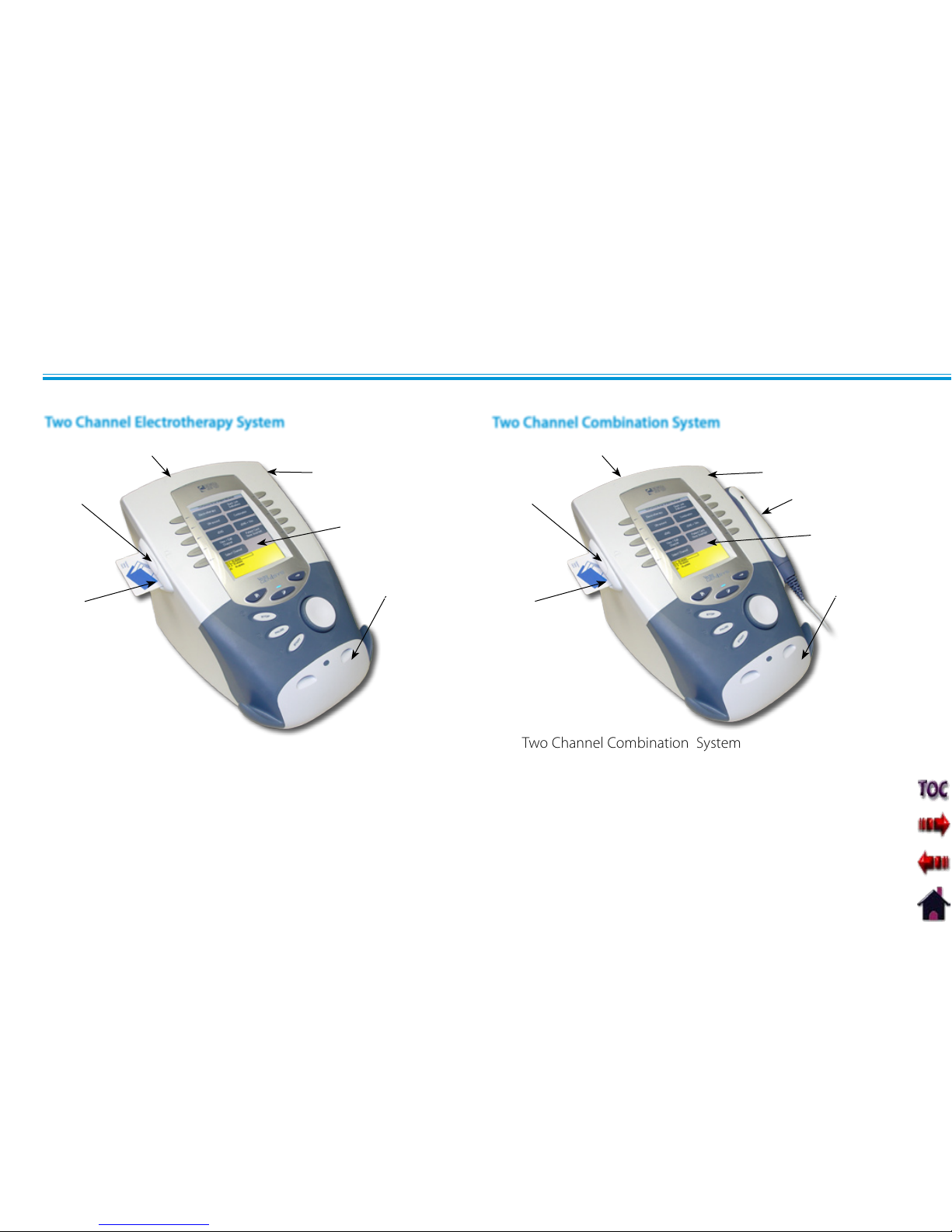
1. Two Channel Combination System
2. User Interface (See Page 15)
3. Front Access Panel
4. Rear Access Panel
5. Patient Data Card and sEMG Data Card access port
6. Multimedia Card (MMC) access port
7. Ultrasound Applicator (5cm
2
shown)
1. Two Channel Electrotherapy System
2. User Interface (See Page 15)
3. Front Access Panel
4. Rear Access Panel
5. Patient Data Card and sEMG Data Card access port
6. Multimedia Card (MMC) access port
Two Channel Electrotherapy System
VECTRA GENISYS ELECTROTHERAPY AND COMBINATION THERAPY SYSTEMS
5
4
6
1
2
3
7
Two Channel Combination System
5
4
6
1
2
3
Page 23
Vectra Genisys® Therapy System
NOMENCLATURE
14
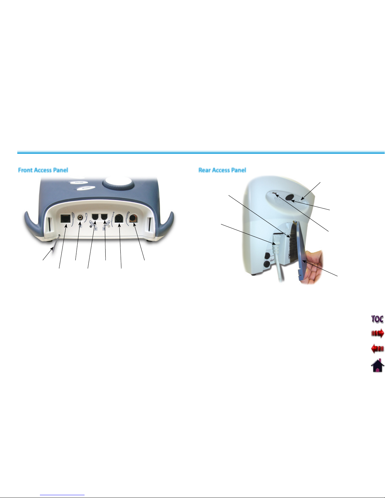
VECTRA GENISYS ELECTROTHERAPY AND COMBINATION THERAPY SYSTEMS (CONTINUED)
1. Screen Contrast Control (Not functional on Color Systems)
2. Power On/Off Switch
3. Technical Maintenance Port
4. Mains Power Cord
5. Rear Access Panel
6. Serial Decal
2
1
3
4
5
1. Front Access Panel Lanyard
NOTE: When reinstalling the Front Access Panel, make
certain the Lanyard does not become kinked.
2. Operator Remote Control Connector
3. Patient Interrupt Switch Connector
4. Channel 1 Lead Wire Connector
5. Channel 2 Lead Wire Connector
6. Microcurrent Probe Connector
7. Ultrasound Applicator Connector
1
2
3
4
5
6
7
6
Rear Access PanelFront Access Panel
Page 24
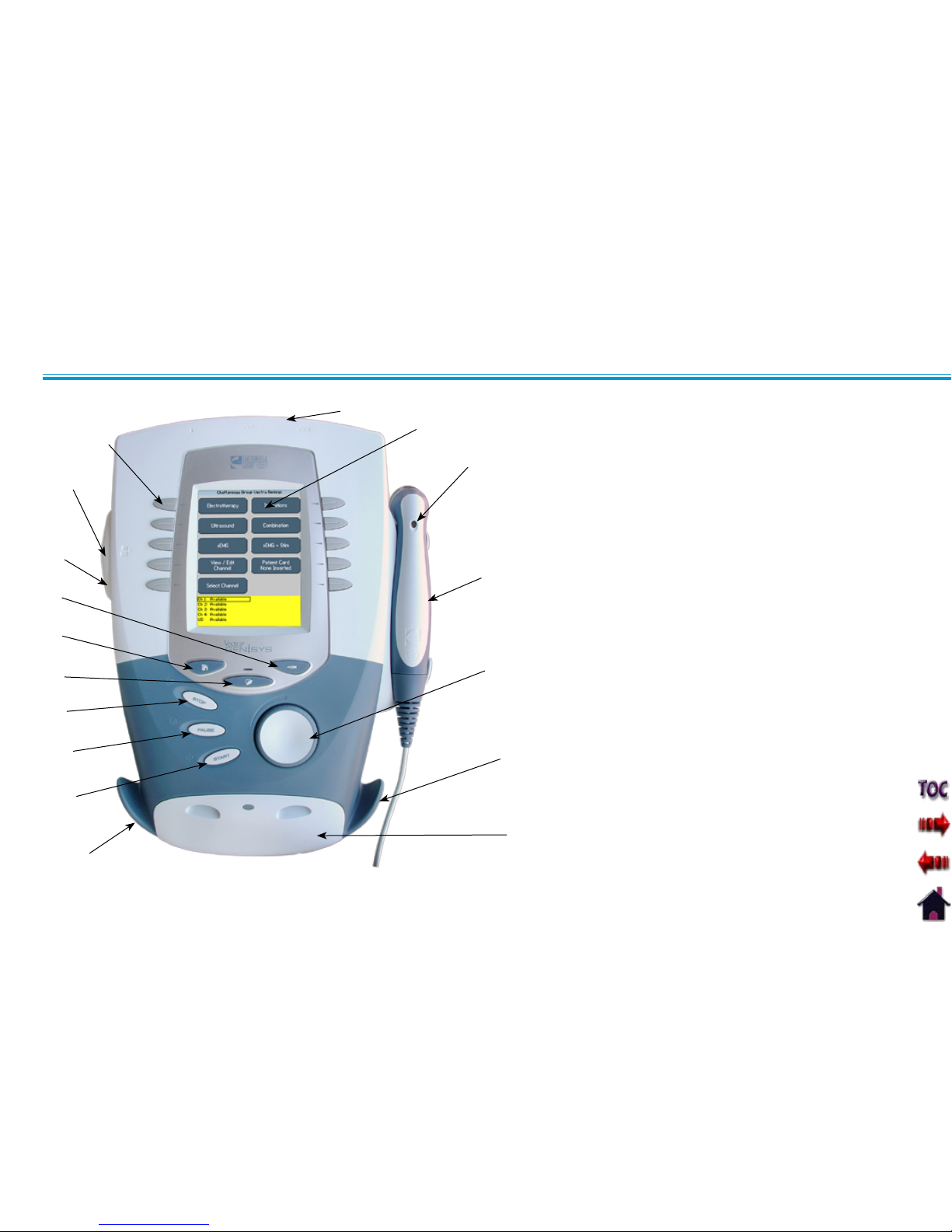
Vectra Genisys® Therapy System
NOMENCLATURE
15
Rear Access Panel 1. (See Page 14)
User Interface2.
Ultrasound LED Coupling Indicator 3.
(Combination only)
Ultrasound Applicator- 5 cm4.
2
Standard.
(Optional 1 cm2, 2 cm2 and 10 cm2 )
applicators available (Combination
only)
Intensity Knob5.
Cable and Lead Wire Hook6.
Front Access Panel 7. (See Page 14)
Start Button8.
Pause Button9.
Stop Button10.
Clinical Resources Library Button11.
Home Screen Button12.
Back Button13.
Patient Data Card and sEMG Data Card 14.
Port
Multimedia Card (MMC) Port15.
User Set Up and Parameter Control 16.
Buttons
1
2
3
4
5
6
7
6
8
9
10
11
12
13
14
16
USER INTERFACE
15
Page 25
Vectra Genisys® Therapy System
NOMENCLATURE
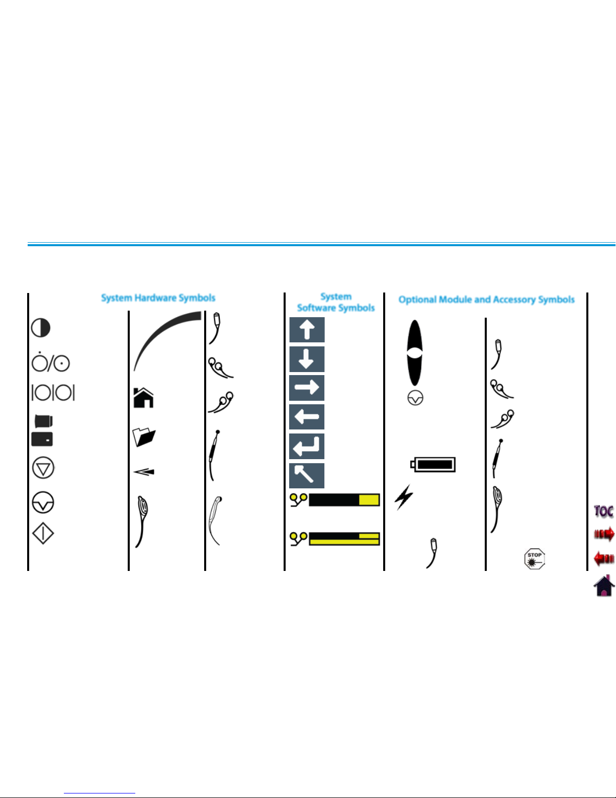
16
SYMBOL DEFINITIONS
Below are the definitions for all of the symbols used in the Vectra Genisys hardware and software. Study and learn these symbols before
any operation of the system.
ON/OFF SWITCH
DATA PORT
MULTIMED IA CARD,
PATIENT DATA CA RD,
AND sEMG DATA CARD
STOP TREATMENT
PAUSE TREATMENT
START TREATMENT
THERAPY
INTENSITY
CONTROL
CHANN EL 1/2
OPERATOR
REMOTE
CONTROL
OPTIONAL
PATIENT INTERRUPT
SWITCH OPTIONAL
CHANNEL 1
LEAD WIRES
CHANNEL 2
LEAD WIRES
MICROCURRENT PROBE
ULTRASOUND
APPLICATOR
HOME
CLINICAL
RESOURCES
LIBRARY
BACK
MOVE UP
MOVE DOWN
MOVE RIGHT
MOVE LEFT
ACCEPT AND
RETURN
DO NOT ACCEPT
AND RETURN
M
INCREASE
INTENSITY
DECREASE
INTENSITY
PAUSE
TREATMENT
MANUAL
STIMULATION
CHANN EL 3 LEAD WIRES
CHANN EL 4 LEAD WI RES
MICROCURRENT PROBE
CHARGE LEVEL
BATTERY CHARGING
CHANN EL 3/4 OPER ATOR
REMOTE CONTROL
OPTIONAL
PATIENT INTERRUPT
SWITCH OPTIONAL
CONTRAST CONTROL
NOT FUNCTIONAL ON
COLOR SYSTEMS
System Hardware Symbols
System
Software Symbols
Optional Module and Accessory Symbols
Operator Remote
Battery Module
Channel 3/4
Electrothrapy
Module
PAD CONTACT QUALITY
SINGLE CHANNEL GRAPH
PAD CONTACT QUALITY
DUAL CHANNEL GRAPH
Patient Interrupt
Switch
Laser Stop Switch
Page 26
Vectra Genisys® Therapy System
NOMENCLATURE
17
Below are the definitions for all of the unique terminology used throughout this manual. Study these and become familiar with these
terms for ease of system operation and familiarization with the components and control functionality of the Vectra Genisys Therapy
System. Some of these terms and definitions refer to a specific button or control on the system. Refer to page 16 for Symbol Definitions.
The dedicated button on the Main unit, below the display, that
each time pressed takes the user back one screen at a time.
The button used in some modalities and
functions that will take the user back one page when reading
multiple pages of text.
Controls used in various modality parameter screens to navigate
or change a value up or down within the parameter.
Refers to the Electrical muscle or nerve Stimulation modalities of
the system.
The primary system with all controls and functions.
Any optional modular modality component designed for
installation onto the System.
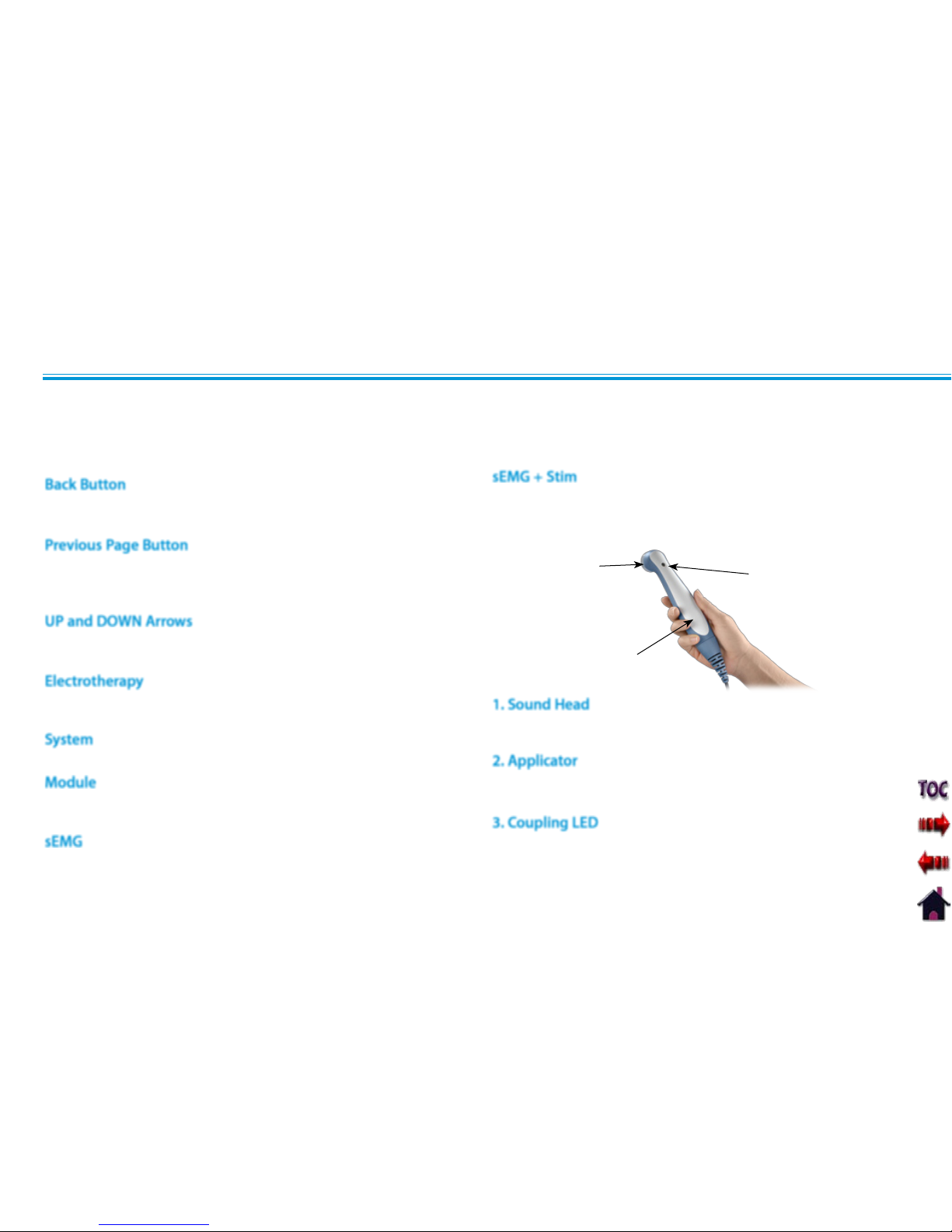
ULTRASOUND
1
GENERAL TERMINOLOGY
That component of the Applicator that makes contact with
the patient during Ultrasound or Combination therapy.
The assembly that connects to the System and incorporates
the Sound Head.
The component of the Applicator which indicates if the
Sound Head is Coupled or Uncoupled on the the treatment
area.
2
Back Button
Previous Page Button
UP and DOWN Arrows
Electrotherapy
System
Module
1. Sound Head
2. Applicator
3. Coupling LED
3
Abbreviation for Surface Electromyography with Triggered
Electrical Stimulation modality.
sEMG
sEMG + Stim
Abbreviation for the Surface Electromyography modality.
Page 27
Vectra Genisys® Therapy System
SPECIFICATIONS
18
Width
Combination System . . . . . . . . . . . . . . . . . . . . . . . . . . . . . . . . 11.375 in (28.9 cm)
Electrotherapy System ................................ 9.750 in (24.8 cm)
Depth (Combination and Electrotherapy System) ..........12.750 in (32.4 cm)
Height (Combination and Electrotherapy System) .........8.750 in (22.2 cm)
Standard Weight
Two Channel Combination System. . . . . . . . . . . . . . . . . . . . . . . . . . 7 lbs (3.2 kg)
Two Channel Electrotherapy System . . . . . . . . . . . . . . . . . . . . . . . . 6 lbs (2.7 kg)
Power (Combination and Electrotherapy Units)
Input ......................................... 100 - 240 V - 1.0 A, 50/60 Hz
Output (Internal Power Supply) ............................... +24 V, 7.3 A
Electrical Class .....................................................CLASS I
Mode of Operation ............................................Continuous
Electrical Type (Degree of Protection)
Ultrasound . . . . . . . . . . . . . . . . . . . . . . . . . . . . . . . . . . . . . . . . . . . . . . . . . . . . TYPE B
Electrotherapy and sEMG .....................................TYPE BF
Regulatory Compliance
UL/IEC/EN 60601-1
IEC/EN 60601-1-2
IEC 60601-2-5
IEC 60601-2-10
NOTE: All waveforms except High Voltage Pulsed Current (HVPC) have
been designed with a 200mA current limit. VMS™, VMS™ Burst and
all TENS waveform output intensities are measured, specified, and
listed to peak, not peak to peak.
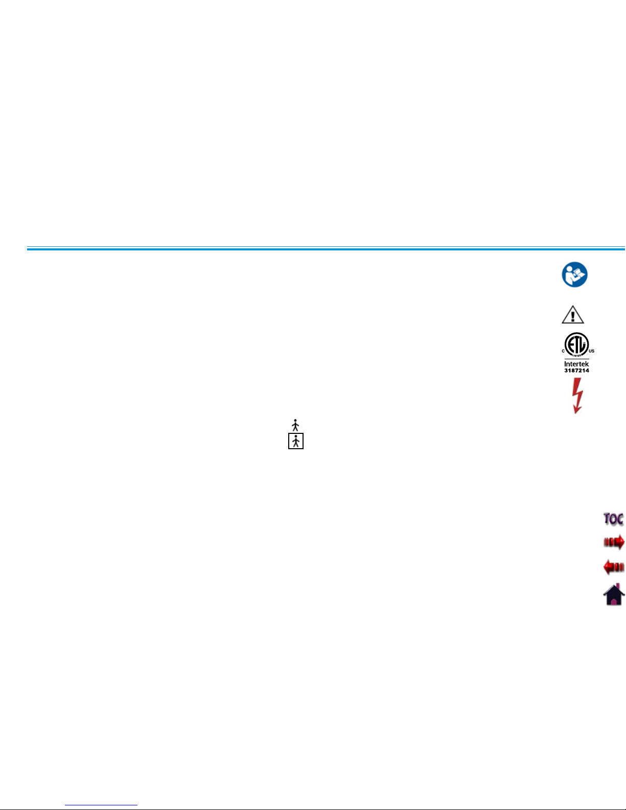
Refer to Instruction Manual/Booklet . . . . . . . . . . . . . . . . . . . . . . . . . . . . . . . . . . . . . . . .
Equipment capable of delivering output
values in excess of 10 mA r.m.s. or 10V r.m.s.
averaged over any period of 5 s . . . . . . . . . . . . . . . . . . . . . . . . . . . . . . . . .
Classified by Intertek Testing Services NA Inc. . . . . . . . . . . . . . . . . . . . . .
Dangerous Voltage . . . . . . . . . . . . . . . . . . . . . . . . . . . . . . . . . . . . . . . . . . . . . . .
SYSTEM SPECIFICATIONS AND DIMENSIONS DESCRIPTION OF DEVICE MARKINGS
Page 28
Vectra Genisys® Therapy System
SPECIFICATIONS
19
WAVEFORM SPECIFICATIONS
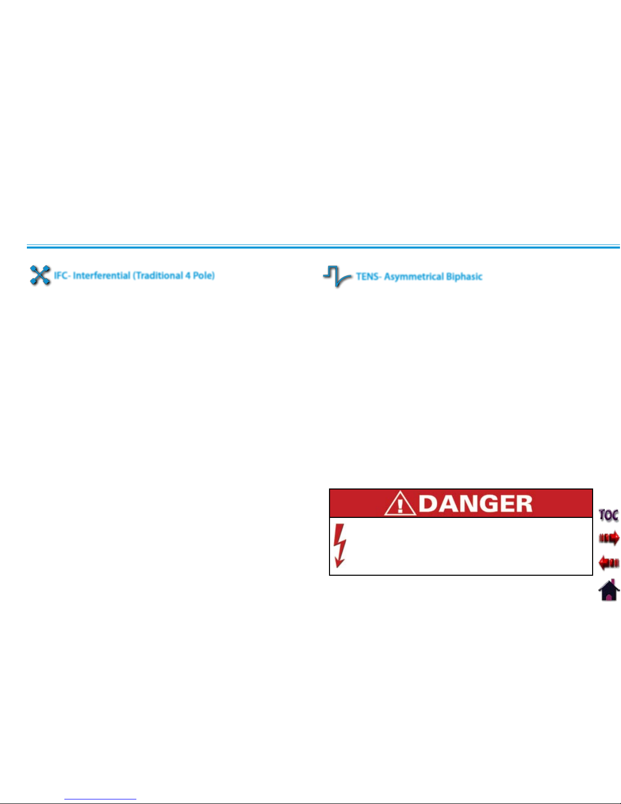
Interferential Current is a medium frequency waveform. Current is
distributed through two channels (four electrodes). The currents
cross each other in the body at the area requiring treatment.
The two currents interfere with each other at this crossing point,
resulting in a modulation of the intensity (the current intensity
increases and decreases at a regular frequency).
Output Mode ..........................................Electrodes
Output Intensity ...................................0-100 mA (CC)
0-100 V (CV)
Carrier Frequency .......................2,500, 4,000 and 5,000 Hz
Beat Frequency (Sweep Off ) ............................1-200 Hz
Sweep Time (Fixed) ........................................15 sec
Sweep Low Beat Frequency . . . . . . . . . . . . . . . . . . . . . . . . . . . . 1-199 Hz
Sweep High Beat Frequency ............................1-200 Hz
Vector Scan ...........................Off, Manual, 40% and 100%
Treatment Time .....................................1-60 Minutes
Mode Selection ........................................ CC or CV*
Available on Channel ............................1&2, 3&4 Option
The Asymmetrical Biphasic waveform has a short pulse duration.
It is capable of strong stimulation of the nerve fibers in the skin
as well as of muscle tissue. This waveform is often used in TENS
devices. Because of its short pulse, the patient typically tolerates
the current well, even at relatively high intensities.
Output Mode ..........................................Electrodes
Output Intensity ...................................0-110 mA (CC)
0-110 V (CV )
Phase Duration .................................... 20-1,000 µsec
Frequency .............................................. 1-250 Hz
Mode Selection ........................................CC or CV*
Burst Frequency . . . . . . . . . . . . . . . . . . . . . . . . . . . . . . . . . . . . . . . . 0-10 bps
Frequency Modulation . . . . . . . . . . . . . . . . . . . . . . . . . . . . . . . . . 0-250 Hz
Amplitude Modulation . . . . . . . . . . . . Off, 40%, 60%, 80% and 100%
Cycle Time ......4/4, 4/8, 7/7, 5/5 4/12, 10/10, 10/20, 10/30, 10/50
Treatment Time .........................................1-60 min
Available on Channels ........................ 1 & 2, 3 & 4 Option
*CC= Constant Current
CV= Constant Voltage
Stimulus delivered by the TENS waveforms of this device,
in certain configurations, will deliver a charge of 25
microcoulombs (µC) or greater per pulse and may be sufficient
to cause electrocution. Electrical current of this magnitude
must not flow through the thorax because it may cause a
cardiac arrhythmia.
IFC- Interferential (Traditional 4 Pole)
TENS- Asymmetrical Biphasic
Page 29
Vectra Genisys® Therapy System
SPECIFICATIONS
20
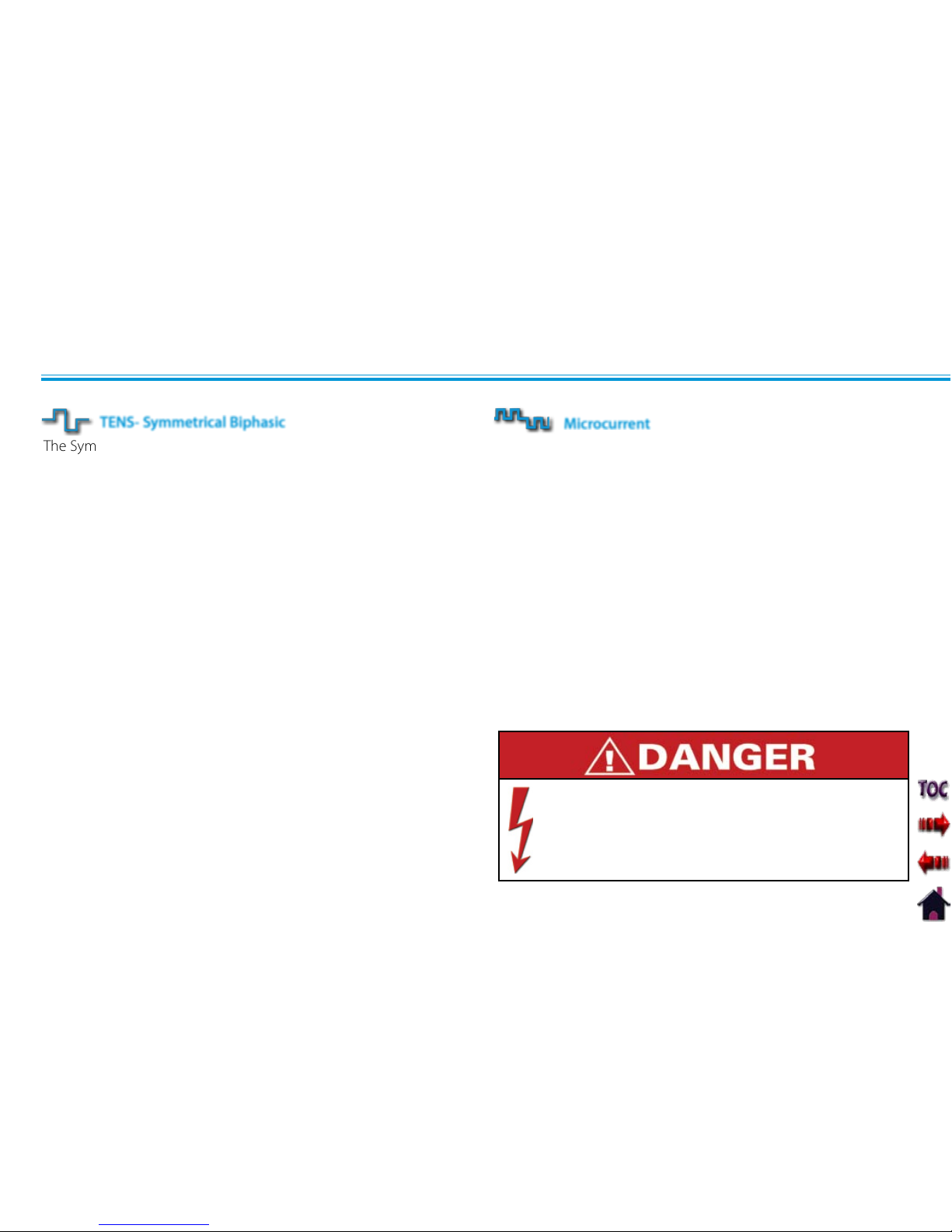
The Symmetrical Biphasic waveform has a short pulse duration
and is capable of strong stimulation of nerve fibers in the skin
and in muscle. This waveform is often used in portable muscle
stimulation units, and some TENS devices. Because of its short
pulse duration, the patient typically tolerates the current well,
even at relatively high intensities.
Output Mode ..........................................Electrodes
Output Intensity ....................................0-80 mA (CC)
0-80 V (CV)
Phase Duration .....................................20-1000 µsec
Frequency .............................................. 1-250 Hz
Mode Selection ........................................ CC or CV*
Burst Frequency . . . . . . . . . . . . . . . . . . . . . . . . . . . . . . . . . . . . . . . . 0-10 bps
Frequency Modulation . . . . . . . . . . . . . . . . . . . . . . . . . . . . . . . . . 0-250 Hz
Amplitude Modulation . . . . . . . . . . . . Off, 40%, 60%, 80% and 100%
Cycle Time ......4/4, 4/8, 7/7, 5/5 4/12, 10/10, 10/20, 10/30, 10/50
Treatment Time .........................................1-60 min
Available on channels . . . . . . . . . . . . . . . . . . . . . . . . 1 & 2, 3 & 4 Option
*CC= Constant Current
CV= Constant Voltage
TENS- Symmetrical Biphasic
WAVEFORM SPECIFICATIONS (CONTINUED)
Stimulus delivered by the TENS waveforms of this device,
in certain configurations, will deliver a charge of 25
microcoulombs (µC) or greater per pulse and may be
sufficient to cause electrocution. Electrical current of this
magnitude must not flow through the thorax because it may
cause a cardiac arrhythmia.
Microcurrent is a monophasic waveform of very low intensity that
closely simulates the electrical current generated by the human
body. Microcurrent can be applied via electrodes or probe.
Output Mode ................................ Electrodes or Probe
Output Intensity ...............................................5-1000 µA
Polarity ..........................Positive, Negative or Alternating
Treatment Time .....................................1-60 Minutes
1-60 Seconds (Probe)
Carrier Frequency ...................................0.1- 1000 Hz
Duty Cycle (Fixed) . . . . . . . . . . . . . . . . . . . . . . . . . . . . . . . . . . . . . . . . . . . 50%
Ramp (Fixed) . . . . . . . . . . . . . . . . . . . . . . . . . . . . . . . . . . . . . . . . . . . 1 second
Available on channels . . . . . . . . . . . . . . . . . . . . . . . . 1 & 2, 3 & 4 Option
Microcurrent
Page 30
Vectra Genisys® Therapy System
SPECIFICATIONS
21
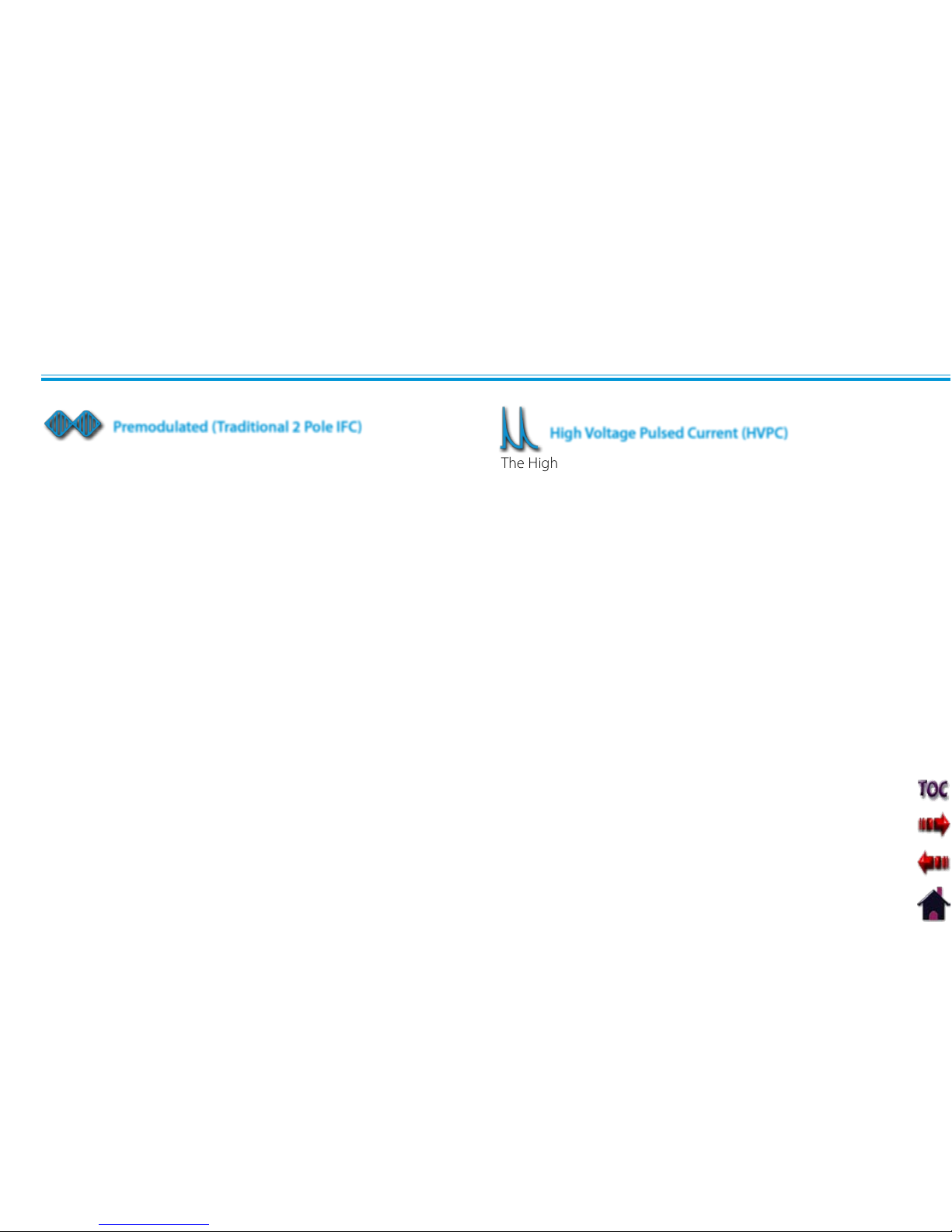
The High Voltage Pulsed Current (HVPC) has a very brief pulse
duration characterized by two distinct peaks delivered at
high voltage. The waveform is monophasic (current flows in
one direction only). The high voltage causes a decreased skin
resistance making the current comfortable and easy to tolerate.
Output Mode ................................ Electrodes or Probe
Output Intensity ..........................................0-500 V
Polarity ......................................Positive or Negative
Ramp ...................................0.5 sec, 1 sec, 2 sec, 5 sec
Display . . . . . . . . . . . . . . . . . . . . . . . . . . . . . . . . . . . . . Peak Current or Volts
Sweep ..............Continuous, 80/120 pps, 1/120 pps, 1/10 pps
Frequency ............................................10-120 pps
Cycle Time ......Continuous, 5/5, 4/12, 10/10, 10/20, 10/30, 10/50
Treatment Time .........................................1-60 Min
Anti-Fatique . . . . . . . . . . . . . . . . . . . . . . . . . . . . . . . . . . . . . . . . . . . .Off or On
Available on Channels ........................ 1 & 2, 3 & 4 Option
*CC= Constant Current
CV= Constant Voltage
WAVEFORM SPECIFICATIONS (CONTINUED)
High Voltage Pulsed Current (HVPC)
Premodulated Current is a medium frequency waveform. Current
comes out of one channel (two electrodes). The current intensity
is modulated: it increases and decreases at a regular frequency
(the Amplitude Modulation Frequency).
Output Mode ..........................................Electrodes
Output Intensity ..........................................0-100 mA (CC)
0- 100 V (CV )
Carrier Frequency (Fixed) . . . . . . . . . . . . . . . . . . . . . . . . . . . . . . . .2,500 Hz
Beat Frequency (Sweep Off ) ............................1-200 Hz
Sweep Time (Fixed) ...................................15 seconds
Sweep Low Beat Frequency . . . . . . . . . . . . . . . . . . . . . . . . . . . . 1-199 Hz
Sweep High Beat Frequency ............................2-200 Hz
Vector Scan ..............................Off, Manual, 40%, and 100%
Mode Selection ............................................... CC or CV*
Treatment Time .........................................1-60 Min
Available on Channel .........................1 & 2, 3 & 4 Option
Premodulated (Traditional 2 Pole IFC)
Page 31

Vectra Genisys® Therapy System
SPECIFICATIONS
22
WAVEFORM SPECIFICATIONS (CONTINUED)
VMS is a symmetrical biphasic waveform with a 100 µsec interphase
interval. Because the pulse is relatively short, the waveform has a low
skin load, making it suitable for applications requiring high intensities,
such as in muscle strengthening protocols.
Output Mode ..........................................Electrodes
Output Intensity ...........................................0-200 mA(CC)
0- 200 V (CV )
Channel Mode ......................... Single, Reciprocal, Co-Contract
Phase Duration ..............................................20-400 µsec
Mode Selection ............................................... CC or CV*
Anti-Fatigue ....................................................Off or On
Set Intensity .....................Individual Channel Intensity Setting in
Reciprocal and Co-Contract modes
Cycle Time ...........Continuous, 5/5, 4/12, 10/10, 10/20, 10/30, 10/50
Frequency .....................................................1-200 pps
Ramp ........................................0.5 sec, 1 sec, 2 sec, 5 sec
Treatment Time .........................................1-60 min
Available on Channels ........................ 1 & 2, 3 & 4 Option
*CC= Constant Current
CV= Constant Voltage
VMS
TM
VMS Burst is a symmetrical biphasic waveform delivered in a burst
format. Because the pulse is relatively short, the waveform has a
low skin load, making it suitable for applications requiring high
intensities, such as in muscle strengthening protocols.
Output Mode ..........................................Electrodes
Output Intensity ...........................................0-200 mA(CC)
0- 200 V (CV )
Channel Mode ......................... Single, Reciprocal, Co-Contract
Phase Duration ..............................................20-400 µsec
Mode Selection ............................................... CC or CV*
Anti-Fatigue ....................................................Off or On
Set Intensity ......................Individual Channel Intensity Setting in
Reciprocal and Co-Contract modes
Cycle Time ...........Continuous, 5/5, 4/12, 10/10, 10/20, 10/30, 10/50
Frequency .....................................................1-200 pps
Ramp ........................................0.5 sec, 1 sec, 2 sec, 5 sec
Treatment Time .........................................1-60 min
Available on Channels ........................ 1 & 2, 3 & 4 Option
VMSTM Burst
Page 32

Vectra Genisys® Therapy System
SPECIFICATIONS
23
Russian Current is a sinusoidal waveform, delivered in bursts or
series of pulses. This method was claimed by its author (Kots)
to produce maximal muscle strengthening effects without
significant discomfort to the patient.
Output Mode ..........................................Electrodes
Output Intensity ...........................................0-100 mA(CC)
0- 100 V (CV )
Carrier Frequency (Fixed) .....................................2,500 Hz
Channel Mode ......................... Single, Reciprocal, Co-Contract
Duty Cycle .............................10%, 20%, 30%, 40%, 50%
Mode Selection ............................................... CC or CV*
Anti-Fatigue ....................................................Off or On
Cycle Time ......Continuous, 5/5, 4/12, 10/10, 10/20, 10/30, 10/50
Burst Frequency . . . . . . . . . . . . . . . . . . . . . . . . . . . . . . . . . . . . . . 20-100 bps
Ramp .......................................... 0.5, 1, 2 and 5 sec
Treatment Time .........................................1-60 min
Available on Channels ........................ 1 & 2, 3 & 4 Option
*CC= Constant Current
CV= Constant Voltage
WAVEFORM SPECIFICATIONS (CONTINUED)
Russian
DC Current is a direct current flowing in one direction only. The
current can be continuous or interrupted.
Output Mode ..........................................Electrodes
Output Intensity ..........................................0-4 mA
Polarity Reversal . . . . . . . . . . . . . . . . . . . . . . . . . . . . . . . . . . . . . . . . On or Off
With Polarity Reversal On, Polarity will change at
50% of treatment time.
Cycle Time ....................................Continuous, 5/60, 10/60
Mode Selection .................................................... CC*
Treatment Time .........................................1-10 min
Available on Channels ........................ 1 & 2, 3 & 4 Option
DC (Direct Current)
Page 33

Vectra Genisys® Therapy System
SPECIFICATIONS
24
Frequency .............................1 MHz, ± 5%; 3.3 Mhz, ±5%
Duty Cycles ...........................10%, 20%, 50%, Continuous
Pulse Frequency ...........................................100 Hz
Pulse Duration .......1 mSec, ±20%; 2 mSec, ±20%; 5 mSec, ±20%
Output Power
10 cm2 Crystal .................0-20 W at 1MHz, 0-10 W at 3.3 MHz
5 cm2 Crystal . . . . . . . . . . . . . . . . . . . . . . . . . . . . . . .0-10 W, 1 and 3.3 MHz
2 cm2 Crystal . . . . . . . . . . . . . . . . . . . . . . . . . . . . . . . .0-4 W, 1 and 3.3 MHz
1 cm2 Crystal . . . . . . . . . . . . . . . . . . . . . . . . . . . . . . . . . 0-2 W 3.3 MHz Only
Amplitude ....................0 to 2.5 w/cm2 in continuous mode,
0-3 w/cm2 in pulsed modes
Output accuracy ...................±20% above 10% of maximum
Temporal Peak to Average Ratio: ....2:1, ± 20%, at 50% Duty Cycle
5:1, ± 20%, at 20% Duty Cycle
9:1, ± 20%, at 10% Duty Cycle
Beam Nonuniformity Ratio . . . . . . . . . . . . . . . . . . . . . . 5.0 : 1 maximum
Beam Type . . . . . . . . . . . . . . . . . . . . . . . . . . . . . . . . . . . . . . . . . . . .Collimating
IPXX Rating for Unit ...........................................IPX0
IPXX Rating for Applicator . . . . . . . . . . . . . . . . . . . . . . . . . . . . . . . . . . . .IPX7
ULTRASOUND SPECIFICATIONS
Ultrasound
Effective Radiating Areas. . . . . . . . . . . . 10 cm
2
Crystal: 6.8 cm
2
– 10 cm
2
5 cm2 Crystal: 3.5 cm2 – 5 cm
2
2 cm2 Crystal: 1.4 cm2 – 2 cm
2
1 cm2 Crystal: 0.7 cm2 – 1 cm
2
Treatment Time ..........................................1-30 min
Head Warming Feature
The Head Warming feature of an Vectra Genisys Combination
Therapy System utilizes Ultrasound output resulting in warming
of the Sound Head to increase patient comfort.
With Head Warming enabled, ultrasound is emitted without
pressing the Start button. The Applicator LED will not illuminate
during the Head Warming period. US Channel will indicate "Head
Warming".
Output . . . . . . . . . . . . . . . . . . . . . . . 0 - 50% Cycling of maximum power
Frequency ................................................ 3.3 Mhz
Sound Head Temperature . . . . . . . . . 29.4 °C - 43.3 °C (85 °F - 110 °F)
Do not apply the Ultrasound Applicator to the patient
during the Head Warming period. Applicator must remain in
Applicator Hook during the Head Warming period.
Page 34

Vectra Genisys® Therapy System
SET UP
25
VECTRA GENISYS THERAPY SYSTEMS
Remove the Vectra Genisys Two or Four Channel Therapy System and all accessories from the shipping carton. Visually inspect for damage.
Report any damage to the carrier immediately.
Contents of Carton:
Vectra Genisys Two or Four Channel Electrotherapy or Combination System
•
sEMG Module (Installed on System)•
Patient Data Cards (1)•
DURA-STICK II 1.25 in (3 cm) Round Disposable Electrodes (2 packs of 4 for use with sEMG and sEMG + Electrical Stimulation)•
sEMG Lead Wires (one for Channel 1 and one for Channel 2)•
Electrotherapy Lead Kit that includes:•
Lead Wires (one for Channel 1 and one for Channel 2)•
DURA-STICK II 2.75 in (7 cm) Round Disposable Electrodes (1 pack of 4)•
Lead Wires- (one for Channel 3 and one for Channel 4 - Four (4) Channel Systems only)•
5 cm•
2
Ultrasound Applicator (Combination Systems Only)
Cord Set•
Conductor Transmission Gel - 1 bottle (Combination Systems Only)•
User Manual•
Page 35

Vectra Genisys® Therapy System
SET UP
26
THERAPY SYSTEM SET UP
Select the row of alpha or numeric
characters desired by pushing the
button beside the corresponding
row. Select the desired character in
the row by pressing the row button
until the desired letter is framed.
NOTE: To add a space, select the
area to the left of the letter
A.
Once selection is framed, press the
Accept and Return Arrow button.
The character just chosen will
display in the top of the screen and
the cursor will advance to the next
character.
To go back a character press the
Move Left Arrow button. To delete
the character, press the Delete
button.
Once Clinic Name is completed,
press the Save button.
To discard entry, press the Back
button.
Plug unit into wall outlet.
Turn system On.
Press the Home and Back buttons
simultaneously.
To return to the System Home
screen, press the Home button.
Press Clinic Name button.
POWER SWITCH
CLINIC NAME BUTTON
ACCEPT AND
RETURN
MOVE
LEFT
SELECT ROW AND CHARACTER BUTTONS
Accessing Operator Utilities
Clinic Name
DELETE SAVE
BACK
Page 36

Vectra Genisys® Therapy System
SET UP
27
THERAPY SYSTEM SET UP (CONTINUED)
Restore Default Protocols
Press Restore Default Protocols
button.
Press Yes button to restore the
Protocols to Factory Settings.
NOTE: This will permanently
remove all User Protocols
and User saved
Sequences.
If it is not desired to permanently
remove all of the User Protocols
and User Sequences from the
System, press the No button.
RESTORE DEFAULT
PROTOCOLS BUTTON
PRESS YES BUTTON TO
RESTORE PROTOCOLS
Press the Restore Default Unit
Settings button to restore the
system defaults. This control will
neither change the Date and
Time nor affect any of the Clinical
Protocols™ stored in the system.
After the settings have been
restored, a message will appear
stating that the Default Unit
Settings are restored. Press any
button to return to Utilities
screen.
Restore Default Unit Settings
PRESS NO BUTTON TO
KEEP PROTOCOLS
AS THEY ARE
RESTORE DEFAULT UNIT
SETTINGS BUTTON
Page 37

Vectra Genisys® Therapy System
SET UP
28
Install Patient Data Card to be
erased into Patient Data Card
Access Port on the system.
Press Erase Patient Card button.
Press the Yes button to erase
all data from Patient Data Card.
Press the No button to keep all
data on Patient Data Card.
After Patient Data Card is
erased, a verification message
will appear. Press any button to
return to the Utilities screen.
ERASE PATIENT
CARD BUTTON
Erase Patient Data Card
THERAPY SYSTEM SET UP (CONTINUED)
INSERT
PATIENT
CARD
NO
BUTTON
YES
BUTTON
Press Set Date and Time button.
Press the UP or Down Arrow
button for the respective area
until desired change is displayed.
After all desired changes are
made, press the Back button to
return to the Utilities screen.
SET DATE
AND TIME
BUTTON
PRESS THE RESPECTIVE UP OR DOWN
ARROW BUTTONS TO CHANGE
Set Date and Time
BACK
BUTTON
YES
BUTTON
Page 38

Vectra Genisys® Therapy System
SET UP
29
Press Volume button until
the desired system volume is
achieved. There are six settings:
Off, X-Low, Low, Med, High and
X-High.
Each time the Volume button is
pressed the setting displayed will
emit three beep tones at that
level.
VOLUME
BUTTON
US COUPLING
BUTTON
THERAPY SYSTEM SET UP (CONTINUED)
Setting System Volume
Pause and Beep
Pauses Treatment Time and
emits an audible beep. When
the Applicator Sound Head is
re-coupled to the patient, the
Treatment Timer will automatically
restart.
Pause and No Beep
Pauses Treatment Timer. When
the Applicator Sound Head is
re-coupled to the patient, the
Treatment Timer will automatically
restart.
Beep
Emits an audible beep.
No Beep
No beep is emitted.
Off
Turns off the Ultrasound
Coupling feature.
Ultrasound Coupling
This warning system works in conjunction with the Applicator
LED to alert the user should the Sound Head become uncoupled
from the patient. Press the US Coupling button until the desired
setting is displayed. There are four different alarm settings and an
Off setting.
Page 39

Vectra Genisys® Therapy System
SET UP
30
Press the Display Unit Version
Information button to show
the system software versions
installed.
Press the Back button to return
the Operator Utilities screen.
PRESS DISPLAY UNIT
VERSION BUTTON TO VIEW
SOFTWARE VERSIONS
BACK
BUTTON
THERAPY SYSTEM SET UP (CONTINUED)
Display Unit Version Information
The Pad Contact Quality feature indicates to the user the contact
quality of the electrodes on the patient. This function, if On,
displays a bar graph at the bottom of Treatment Review screen for
the following waveforms only:
The Therapy System Pad Contact Quality default is ON.
PAD CONTACT QUALITY
BUTTON
Pad Contact Quality
Interferential:
•
Dual Channel Graph
IFC Premod (2p):•
Single Channel Graph
Russian: •
Single Channel Graph
To turn On or Off, press Pad
Contact Quality button until On
or Off as desired is displayed.
Single Channel Waveforms will
display a single bar graph. Dual
Channel waveforms will display a
double bar graph.
Contact quality is measured by
the amount of the graph filled
with black.
An ideal contact quality is 75% or
more of the graph filled.
SINGLE CHANNEL GRAPH
DUAL CHANNEL GRAPH
GOOD CONTACT
QUALITY
CHANN EL 1:
GOOD CONTACT QUALITY
CHANN EL 2:
NO CONTACT QUALITY
Page 40

Vectra Genisys® Therapy System
SET UP
31
Install Lead Wires, Ultrasound Applicator, Patient Interrupt Switch
and any other accessories according to the Front Access Panel as
illustrated below. Refer to page 16 for Symbol Definitions.
To change the language
displayed on the system, press
the Language button until the
desired language is displayed.
Press Home button to set the
language and return to Home
screen.
If Unit Default Settings are
restored, the language will revert
back to English.
LANGUAGE
BUTTON
PRESS HOME BUTTON
TO SET LANGUAGE
THERAPY SYSTEM SET UP (CONTINUED)
Select Language
Connecting Accessories to the Therapy System
OPERATOR REMOTE
OPTIONAL
CHANN EL 1/2
PATIENT INTERRUPT SWITCH
OPTIONAL
CHANNEL 1
LEAD WIRE
BLACK
CHANNEL 2
LEAD WIRE
GREY
MICROCURRENT PROBE
OPTIONAL
ULTRASOUND APPLICATOR
COMBO SYSTEMS ONLY
Page 41

Vectra Genisys® Therapy System
PATIENT PREPARATION
32
Examine the skin for any wounds and clean the skin.•
Apply the electrodes to the treatment area.•
Ensure the electrodes are applied securely to the skin.•
Ensure good contact between each electrode and the skin.•
Check the electrode contact regularly during the treatment.•
Examine the skin again after the treatment.•
Choose electrodes that fit the anatomy.•
View the Electrode Placement recommendations in the •
Treatment Review screen for the particular modality being used
for treatment as a reference point only prior to administering
treatment.
Refer to the respective electrode type instructions on • pages 33
through 35.
Follow electrode manufacturer instructions.•
ELECTROTHERAPY PATIENT PREPARATION
Electrode Placement
Keep electrodes separated during treatment. Electrodes in •
contact with each other could result in improper stimulation
or skin burns.
Output current density is related to electrode size. Improper •
application may result in patient injury. If any question arises
as to the proper electrode size, consult a licensed practitioner
prior to therapy session.
Powered muscle stimulators should be used only with •
the leads and electrodes recommended for use by the
manufacturer.
Page 42

Vectra Genisys® Therapy System
PATIENT PREPARATION
33
DURA-STICK™ Electrodes
Chattanooga DURA-STICK Electrodes are a self adhesive,
disposable product designed specifically for use with Chattanooga
Electrotherapy systems.
It is recommended that Chattanooga DURA-STICK Electrodes be
used whenever possible to ensure the highest level of contact
with the treatment area and most uniform delivery of the
prescribed electrotherapy treatment.
Reusable Carbon Electrodes (Optional)
If used for delivery of electrotherapy, the Carbon Electrodes
must be used with a conductive medium such as Conductor™
Transmission Gel.
These Carbon Electrodes should be secured to the treatment area
using Nylatex® Wraps.
ELECTROTHERAPY PATIENT PREPARATION (CONTINUED)
Page 43
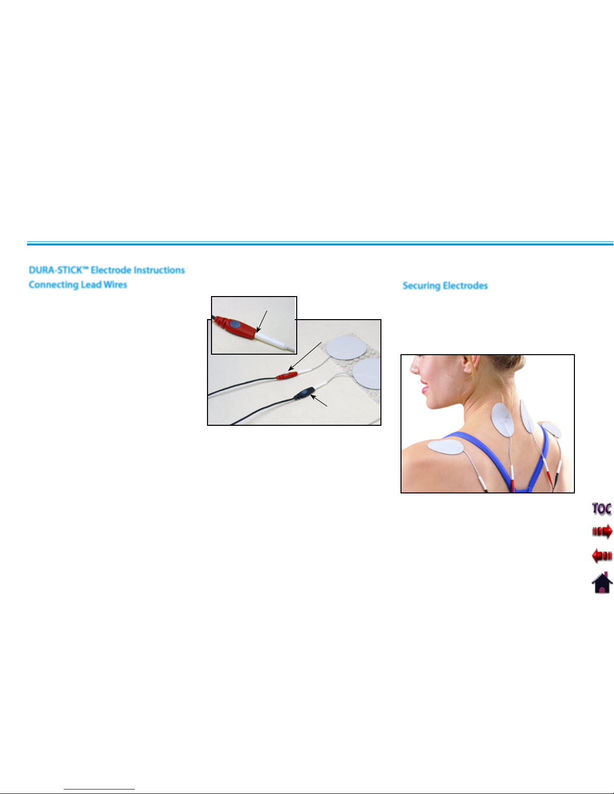
Vectra Genisys® Therapy System
PATIENT PREPARATION
34
ELECTROTHERAPY PATIENT PREPARATION (CONTINUED)
Insert the lead with the Red (+) electrode
connector into one DURA-STICK Electrode.
Insert the lead with the Black (-) electrode
connector into the other electrode.
Make certain the lead wires are
seated completely into the electrodes.
NOTE: Use of conductive medium
or sponges is not required or
recommended. DURA-STICK
Electrodes are manufactured to
ensure the optimum conductivity
during therapy when properly
applied.
DURA-STICK™ Electrode Instructions
Connecting Lead Wires
Remove the DURA-STICK Electrodes from
the protective backing and apply to the
treatment area as prescribed. Ensure the
entire electrode surface is in contact with
patient skin by pressing into place.
Securing Electrodes
RED +
LEAD WIRE
BLACK
LEAD WIRE
LEAD WIRE SEATED
Page 44

Vectra Genisys® Therapy System
PATIENT PREPARATION
35
Securing Electrodes
Liberally apply Conductor™ Transmission
Gel to electrode prior to placement on
patient.
Conductive Medium
Use Nylatex
®
Wrap to secure each electrode
in position on the patient.
Connecting Lead Wires
Insert the lead with the Red (+) electrode
connector into Red electrode. Insert the
lead with the Black (-) electrode connector
into the Black electrode.
Make certain the lead wires are seated
completely into the electrodes.
RED +
LEAD WIRE
BLACK
LEAD WIRE
ELECTROTHERAPY PATIENT PREPARATION (CONTINUED)
Reusable Carbon Electrodes (Optional)
LEAD WIRE
SEATED
SECURE WITH
NYLATEX
Nylatex® Wraps contain dry natural rubber and may
cause allergic reactions in patients with allergies to
latex.
Page 45

Vectra Genisys® Therapy System
PATIENT PREPARATION
36
NOTE: Refer to page 29 f o r U S
Coupling settings.
Examine the skin for any wounds and clean the skin.
Liberally apply Conductor™
Transmission Gel or equivalent to
the treatment area on the patient.
COUPLING
INDICATOR
LED
ULTRASOUND PATIENT PREPARATION
Preparing Treatment Area
View the Sound Head Recommendation in the Treatment
Review screen for Ultrasound (as a reference point only) prior to
administering treatment.
Sound Heads are available in the sizes shown below.
Size of Applicator
Clean applicator before each therapy session with warm soapy
water.
1 CM
2
2 CM
2
5 CM
2
STANDARD
10 CM
2
Applicator Preparation
Conductive Medium
APPLY
CONDUCTIVE GEL
If US Coupling is On, the Sound
Head is properly coupled to
the patient and administering
ultrasound when the LED is
constantly illuminated.
Treatment Area
Move the Sound Head during
therapy session in a circular
motion. The area treated should
be two times the diameter of the
Sound Head.
Applicator Coupling
Page 46

Vectra Genisys® Therapy System
PATIENT PREPARATION
37
Install sEMG Lead Wires to System
Connect a DURA-STICK II 1.25 in (3 cm)
disposable electrode to each lead. These
electrodes are designed for use with
Chattanooga equipment and will provide
an accurate reading of sEMG activity.
Leave electrodes on the protective
backing until treatment area has been
prepared.
sEMG AND sEMG+STIM PATIENT PREPARATION
Remove the Front Access Cover from the
Therapy System and remove the existing
Lead Wires. Connect the sEMG Lead wires
to the channel(s) desired for use with the
sEMG or sEMG + Stim modality.
CONNECT sEMG LEAD WIRES
Replace the Front Access Cover.
NOTE: Two Channels may be used for
sEMG Therapy at the same time. If four
electrotherapy channels are available, a
maximum of only two may be used at a
time and must be channels 1/2 or 3/4.
Install DURA-STICK™ II Electrodes Select Modality
Press the sEMG or sEMG + Stim button as
required for the therapy prescribed.
PRESS sEMG OR sEMG+STIM BUTTON
REFERENCE GREEN LEAD
ACTIVE RED LEAD
ACTIVE BLACK
LEAD
This section applies only to models
capable of supporting the functions of the
sEMG module.
Page 47

Vectra Genisys® Therapy System
PATIENT PREPARATION
38
sEMG AND sEMG+STIM PATIENT PREPARATION (CONTINUED)
Select Body Area
Press the Electrode Placement button to
view the Select Body Area screen.
Press the Up and Down Arrow buttons
until the area desired is highlighted.
UP ARROW BUTTON
DOWN ARROW
BUTTON
NOTE: The Page Up and Page Down
buttons allow navigation either
at the top or bottom of
the available selections.
Press the Accept and Return Arrow button
to view the specific electrode placement
graphic.
NOTE: As illustrated, the two Black
electrodes represent Active
electrodes and the one White
electrode represents
the Reference electrode.
View Electrode Placement Graphic
ELECTRODE PLACEMENT BUTTON
ACCEPT AND RETURN
ARROW BUTTON
Page 48

Vectra Genisys® Therapy System
PATIENT PREPARATION
39
sEMG AND sEMG+STIM PATIENT PREPARATION (CONTINUED)
BACK
BUTTON
View Electrode Placement Text
Press the Next Page button to view
text relating to the specific electrode
placement selected and typical conditions
of the area.
Press the Next Page button to view
additional text.
Press the Prev Page button to review the
previous page.
Press the Back button to return to the
Select Body Area screen.
Press the Back button a second time to
return to the Treatment Review screen.
NEXT PAGE
BUTTON
PREV PAGE
BUTTON
Prepare Treatment Area
Examine the skin for any wounds.
Thoroughly clean the treatment area by
scrubbing the skin with water and mild
antibacterial soap.
NOTE: Thorough and proper cleaning
of the treatment area to remove
any topical medication and
cream film as well as loose
skin particles from the treatment
area is critical to the skin contact
and reception of the Electrodes
during sEMG and sEMG + Stim
therapy.
NEXT PAGE BUTTON
Page 49

Vectra Genisys® Therapy System
PATIENT PREPARATION
40
Electrode Placement
sEMG AND sEMG+STIM PATIENT PREPARATION (CONTINUED)
Using DURA-STICK™ II 1.25 in (3 cm)
electrodes, place the Active (red and
black lead) electrodes in the center of the
muscle belly and parallel with the muscle
fibers.
Position the Reference electrode (green
lead) in close proximity to the treatment
area. Review the specific Electrode
Placement graphic for positioning of the
Reference (green lead) electrode.
NOTE: The electrodes may be placed
for specific, general and
quasi-specific biofeedback muscle
or muscle group activity.
Using small electrodes and placing them
closer together will render a more specific
reading of muscle activity during sEMG
and sEMG + Stim therapy.
The Active electrodes may be placed
farther apart to obtain a general reading of
a muscle or muscle group activity during
the session.
DJO, LLC recommends using only DURASTICK™ II electrodes to obtain the most
accurate sEMG feedback.
Follow the electrode manufacturer
instructions.
Trimming or cutting electrodes may
interfere with the reception of sEMG data
and may affect the delivery of electrical
stimulation in the sEMG + Stim Modality.
Keep stim electrodes separated during •
sEMG + Stim treatment. Electrodes in
contact with each other could result in
improper stimulation or skin burns.
Long term effects of chronic electrical
•
stimulation are unknown.
Stimulation should not be applied over
•
the anterior neck or mouth. Severe spasm
of the laryngeal and pharyngeal muscles
may occur and the contractions may be
strong enough to close the airway or cause
difficulty in breathing.
If using the Intra-Vaginal Probe, plug the
active ends of the sEMG lead wire (red and
black) into the Intra-Vaginal Probe.
The Intra-Vaginal Probe is for single
patient use only. Refer to the instructions
packaged with the probe for proper use,
care and disposal.
Intra-Vaginal Probe
REFERENCE
GREEN LEAD
ACTIVE
RED
LEAD
ACTIVE
BLACK
LEAD
Page 50

Vectra Genisys® Therapy System
41
OPERATION
The Vectra Genisys Therapy System Operator Interface houses all of the functions and controls necessary for the operator to access all
operator utilities, modalities and parameters for modification and system set up.
1
2
3
5
4
6
11
12
Top of Screen1.
The Title Bar indicates the Screen Title for
the modality being used. When at the
System Home screen, the Clinic Name is
displayed.
Center of Screen2.
Contains available Modality options.
Select Modality by pressing the desired
Modality button and then make
parameter modifications.
Bottom of Screen3.
Displays available channels and their
respective status. Displays Treatment
Time and status. After starting therapy
session, Modality and Parameter buttons
are used to select and modify channel
parameters.
Unit On Indicator4.
Illuminates green when System is
connected to an AC mains power source.
When the System is On, the indicator
will illuminate blue. With System On,
and if the system sits unused, the Screen
Saver initiates (blank screen) and the Blue
Indicator will flash.
Back button5.
Used to return back one screen. Used in
conjunction with the Home button to
access the Operator Utilities screen.
OPERATOR INTERFACE
Clinical Resources Library button6.
Used to access Clinical Protocols™, User
Protocols, Sequencing, and the Clinical
(Anatomical/Pathological) Libraries
screen.
Intensity Knob 7.
Rotate clockwise to increase Modality
intensity. Rotate counterclockwise to
decrease Modality intensity.
Start button 8.
Press to start therapy session after all
initial parameters have been set.
Pause button 9.
Press to pause a therapy session. Press
again to restart session.
Stop button 10.
Press to completely stop the therapy
session.
Home button11.
Used to go back to the System Home
screen. Used in conjunction with the
Back button to access the Operator
Utilities screen.
Modality and Parameter buttons12.
Used to select modality and edit
treatment parameters.
7
8
9
10
Page 51

Vectra Genisys® Therapy System
42
OPERATION
Electrotherapy1.
Accesses all the available waveforms and parameter editing controls.
Indications2.
Accesses specific pre-programmed indications, for general reference only, which
aid in selecting the proper waveform and electrode placement for particular
indicated patient syndrome diagnoses.
Ultrasound3.
Accesses the Ultrasound set up screen and parameter editing controls.
Combination4.
Accesses combination therapy set up screens and parameter editing controls.
sEMG5.
Accesses the Surface EMG (sEMG) modality and parameter editing controls.
sEMG + Stim6.
Accesses the Surface EMG (sEMG) + Electrical Stimulation modality and
parameter editing controls.
View/Edit Channel7.
Accesses the selected channel and allows editing of the channel's parameters
during therapy. Also used in the saving of information to the Patient Data Card.
Patient Card8.
Accesses Patient Data Card data.
Select Channel9.
Use to select desired channel for viewing and editing of channel parameters.
Unused10.
Reserved for optional expansion Modules.
1
3
5
7
2
4
6
8
10
9
HOME SCREEN
The Vectra Genisys Home screen affords access to all of the system modalities and functions. The area surrounding the screen has 10 modality
and parameter modification buttons.
Page 52

Vectra Genisys® Therapy System
43
OPERATION
The screen allows the operator to access, set up, and modify
parameters of each of the available waveforms within the Vectra
Genisys Therapy System. The following pages give a general
explanation of a treatment setup.
Refer to the Specifications section, beginning on page 18,
for detailed specifications of the system and each available
waveform.
ELECTROTHERAPY SCREEN
Page 53

Vectra Genisys® Therapy System
44
OPERATION
Refer to pages 32 through 35 for
electrode selection, preparing patient, and
securing electrodes.
GENERAL ELECTROTHERAPY WAVEFORM SET UP
The following information is an example of step by step set up for the Electrotherapy waveforms. All waveforms in the Vectra Genisys
Therapy System are set up and edited in the same basic fashion. The following set up instructions use Interferential Waveform.
Press the Electrotherapy button on the
Home screen.
Press button beside the desired waveform
from the listing on the screen.
Press the Waveform Description button
to view text explaining the waveform
rationale.
Refer to Specifications section of this
manual for all available waveforms on the
Vectra Genisys Therapy System.
Press the Next Page button to view
additional text. Press the Back button to
return to the Treatment Review screen.
ELECTROTHERAPY
BUTTON
Select Modality
Select Waveform
PRESS DESIRED WAVEFORM BUTTON
Prepare Patient
View Waveform Description
WAVEFORM DESCRIPTION
BUTTON
NEXT
PAGE
BUTTON
BACK
BUTTON
Page 54

Vectra Genisys® Therapy System
45
OPERATION
Make certain the Patient Interrupt Switch is
connected to the Therapy System. Refer to
page 16 for Symbol Definitions.
GENERAL ELECTROTHERAPY WAVEFORM SET UP (CONTINUED)
Press the Electrode Placement button to
view the most commonly used electrode
placement for the waveform selected.
Press the Next button to read Electrode
Placement Text. Press the Back button to
return to the Treatment Review screen.
View Electrode Placement
NEXT
PAGE
BUTTON
BACK
BUTTON
Press Edit button to access waveform
parameters.
Press the corresponding button to edit
each parameter as prescribed.
Press the Back button to return to the
Treatment Review screen.
Edit Waveform Parameters
EDIT
BUTTON
PARAMETER
BUTTONS
NOTE: When reinstalling the Front Access
Panel, make certain the Lanyard
does not become kinked.
Install Optional Patient Interrupt Switch
LANYARD
PATIENT
INTERRUPT
SWITCH
BACK
BUTTON
ELECTRODE PLACEMENT
BUTTON
Page 55

Vectra Genisys® Therapy System
46
OPERATION
Give Patient Interrupt Switch to patient
and explain that pressing the Red button
once pauses the therapy session.
GENERAL ELECTROTHERAPY WAVEFORM SET UP (CONTINUED)
Optional Patient Interrupt Switch
Set intensity by rotating the Intensity Control
Knob to the prescribed level.
Set Waveform Intensity
PRESSING BUTTON ONCE PAUSES SESSION
INTENSITY
DISPLAYED
ROTATE
INTENSITY
KNOB
Clockwise- Increases Intensity
Counterclockwise- Decreases Intensity
Intensity Knob Rotation
If Patient Interrupt Switch is depressed, the
treatment will be paused and a message
will appear on the System screen.
Press any button to clear the message.
NOTE: If the Patient Interrupt Switch
is depressed a second time,
the message will clear from
the screen and the treatment
will remain paused.
Start Treatment
Press the Start button to begin therapy
session.
START
BUTTON
Page 56

Vectra Genisys® Therapy System
47
OPERATION
After session is complete, press the Save
to Patient Card button. Refer to pages 80
through 89 for Patient Data Card Setup
and use.
GENERAL ELECTROTHERAPY WAVEFORM SET UP (CONTINUED)
Pause Treatment
Press the Pause button to pause therapy
session and maintain remaining time. To
resume treatment, press the Pause button
again.
Stop Treatment
To Stop treatment, press the Stop button
once. Treatment will stop and the
Completed Treatment Review screen will
display.
Save to Patient Data Card
PAUSE
BUTTON
STOP BUTTON
Page 57

Vectra Genisys® Therapy System
48
OPERATION
When finished editing the selected
channel, press the Home button to select
another channel if desired.
To view the Treatment Review screen, if
the Home screen is displayed, press the
View/Edit Channel button. If the Edit
screen is displayed, press the Back button.
PARAMETER
BUTTONS
ADJUSTING ELECTROTHERAPY CHANNEL PARAMETERS DURING TREATMENT
Select Channel
Press the Edit button. Edit parameters as
desired.
Press the Home button.
Press the Select Channel button until the
channel desired is framed.
The Electrotherapy channel parameters may be changed during a treatment session without pausing or stopping the treatment. The
waveform Intensity may be increased or decreased at any time during the session without utilizing this process.
SELECT CHANNEL
BUTTON
DESIRED
CHANNEL
FRAMED
VIEW/EDIT
BUTTON
Press the View/Edit Channel button. The
Treatment Review screen will display.
Edit Channel Paramenters
EDIT
BUTTON
Page 58

Vectra Genisys® Therapy System
49
OPERATION
Refer to page 36 for Applicator sizes,
patient preparation, and use of conductive
medium.
NOTE: Use only Vectra Genisys
Ultrasound Applicators. Previous
models of Chattanooga Ultrasound
Applicators will not work with the
Vectra Genisys Therapy System.
Press the Parameter Rationale button for
text. Press the Next Page button to continue
viewing text.
Press Sound Head Recommendation
button to view text explaining how to select
an Ultrasound Applicator size based on
treatment area.
ULTRASOUND
BUTTON
ULTRASOUND
The Vectra Genisys Therapy System Ultrasound modality allows the user to select specific Sound Head recommendations and edit treatment
parameters for various syndromes requiring the use of ultrasound therapy. The following information gives general instructions for the
setup of ultrasound therapy when selecting Ultrasound from the Home screen. Clinical Protocols™, Indications, and Ultrasound treatment
parameters are edited in their respective fashions.
Press the Ultrasound button on the Home
screen.
Select Modality
Prepare Patient View Parameter Rationale
PARAMETER RATIONALE
BUTTON
NEXT
PAGE
BUTTON
BACK
BUTTON
Press the Back button to the return to
Treatment Review screen.
Sound Head Recommendation
BACK
BUTTON
Press the Back button to the return to
Treatment Review screen.
SOUND HEAD
RECOMMENDATION
BUTTON
Page 59

Vectra Genisys® Therapy System
50
OPERATION
ULTRASOUND (CONTINUED)
Press Edit button to access ultrasound
parameters.
Press the corresponding button to edit as
prescribed.
The Vectra Genisys Therapy System
incorporates a Head Warming feature that
pre-heats the Sound Head of the Applicator
for increasing patient comfort. The control
for the Head Warming feature is in the Edit
screen of the Ultrasound modality.
Press the Head Warming button until On is
displayed.
NOTE:
Head Warming time is
approximately 2 minutes.
Edit Ultrasound Parameters
Press the Back button to return to
Treatment Review screen.
PARAMETER
BUTTONS
BACK
BUTTON
Head Warming
HEAD
WARMING
BUTTON
To set the default of the Head Warming
feature to On, press the Home button after
On is displayed in the Head Warming icon.
Head Warming will then start when the
Therapy System is turned On.
Set intensity by rotating the Intensity Control
Knob to the prescribed level.
Set Ultrasound Intensity
INTENSITY
DISPLAYED
ROTATE
INTENSITY
KNOB
Clockwise- Increases Intensity
Counterclockwise- Decreases Intensity
Intensity Knob Rotation
EDIT
BUTTON
Page 60

Vectra Genisys® Therapy System
51
OPERATION
NOTE: If US Coupling is On and
the Sound Head loses coupling
with the treatment area the session
will pause. When coupling is
reestablished the session will
automatically restart. See
page 29 for US Coupling settings.
After session is complete, press the Save
to Patient Card button. Refer to pages 80
through 89 for Patient Data Card Setup
and use.
Press the Pause button to pause therapy
session and maintain remaining time. To
resume treatment, press the Pause button
again.
or
If US Coupling is On, and the Sound
Head loses coupling with the treatment
area, the session will pause. When
coupling is reestablished, the session will
automatically restart. Refer to page 29 for
US Coupling settings.
ULTRASOUND (CONTINUED)
Start Treatment
Press the Start button to begin therapy
session.
Move the Applicator in a circular motion
over the treatment area.
Pause Treatment
Stop Treatment
To Stop treatment, press the Stop button
once. Treatment will stop and the
Treatment Review screen will display.
Save to Patient Data Card
START
BUTTON
PAUSE
BUTTON
STOP BUTTON
Page 61

Vectra Genisys® Therapy System
52
OPERATION
Press Select Channel button until US:
Running is framed.
Press View/Edit Channel button.
Press the Edit button on the Treatment
Review screen.
The ultrasound parameters may be changed during a treatment session without pausing or stopping the treatment. The following
information provides instructions for changing ultrasound treatment parameters during a treatment session. The ultrasound intensity may
be increased or decreased at any time during the session without utilizing this process.
ADJUSTING ULTRASOUND PARAMETERS DURING TREATMENT
Editing Ultrasound from Home Screen
SELECT
CHANNEL
BUTTON
VIEW/EDIT
CHANNEL
BUTTON
US: RU NNING
FRAMED
When editing is complete, press the Back
button to return to Treatment Review
screen.
PARAMETER
BUTTONS
BACK
BUTTON
Press the corresponding parameter button
and edit as prescribed.
Editing Ultrasound from Treatment
Review Screen
Press the Edit button on the Treatment
Review screen.
Press the corresponding parameter button
and edit as prescribed.
PARAMETER
BUTTONS
BACK
BUTTON
When editing is complete, press the Back
button to return to Treatment Review
screen.
EDIT
BUTTON
EDIT
BUTTON
Page 62

Vectra Genisys® Therapy System
53
OPERATION
sEMG THERAPY SET UP
The Vectra Genisys sEMG modality reads and records the sEMG biofeedback activity of a muscle or muscle group by sensing the electrical
impulses generated during a voluntary muscle contraction and relax cycle. These signals are accurately relayed to the Vectra Genisys
Therapy System through 1.25 in (3 cm) DURA-STICK™ II Disposable Electrodes.
sEMG can be beneficial to muscle retraining therapy by setting target values and charting the patient progress in reaching those goals in a
specific muscle or muscle group.
Within this section, general set up procedures of the various parameters of sEMG are explained. Also, set up and use of the optional sEMG
Data Card for recording sEMG Data are demonstrated.
NOTE: This section applies only to models capable of supporting the functions of the sEMG module.
General Information
The sEMG data can be recorded onto the optional
sEMG Data Card and viewed in graph form via the
optional Patient Data Management System connected
to a Windows ® PC. This allows the clinician to record
session activity, as well as see progress the patient
may be making through therapy, saving the data and
printing patient graphs and reports.
Illustrated is an example of the sEMG Graph through
the optional Patient Data Management System
(PDMS).
Optional Patient Data Management System (PDMS)
Page 63

Vectra Genisys® Therapy System
54
OPERATION
Channel1.
Select Channel 1, Channel 2, or Channel 1+2. Channel 1+2 is the Default Unit
Setting.
Target2.
Select Average, Max, or Manual Target. Max Target is the Default Unit Setting.
Alarm3.
Set Alarm to sound Above, Below, or at Target. Above Target is the Default Unit
Setting.
Capture Target4.
Captures target value while patient is performing a series of muscle contractions.
Audio5.
Allows selection of Constant, Pulsed, or Dynamic audio types. Constant is the
Default Unit Setting.
Volume6.
Set volume level to Low, Medium, High, or Off. Medium is the Default Unit Setting.
1
3
5
2
4
6
The Vectra Genisys sEMG screen affords access to all of the sEMG parameters and functions. The area surrounding the screen has 10 parameter
modification buttons. However, only six are used for the sEMG modality. Below is a general description of each of the sEMG parameter
buttons. Each sEMG parameter button is explained in greater detail in the following pages of this section.
sEMG THERAPY SET UP (CONTINUED)
sEMG Screen
Page 64

Vectra Genisys® Therapy System
55
OPERATION
Refer to pages 37 through 40 for Patient
Preparation and Electrode Placement.
Prepare Therapy System and patient. Refer
to pages 37 through 40.
sEMG THERAPY SET UP (CONTINUED)
Prepare System and Patient
Press the sEMG button on the Home
screen.
Select sEMG Modality
sEMG
BUTTON
Press the sEMG Description Text button to
view text explaining the rationale of sEMG
Therapy.
View sEMG Description Text
sEMG DESCRIPTION TEXT
BUTTON
Press the Next Page button to view
additional text.
Press the Prev Page button to review
previous page.
Press the Back button to return to the
Treatment Review screen.
BACK
BUTTON
NEXT PAGE
BUTTON
PREV PAGE
BUTTON
Electrode Placement
Page 65

Vectra Genisys® Therapy System
56
OPERATION
sEMG THERAPY SET UP (CONTINUED)
Select Edit
Press the Edit button on the Treatment
Review screen to edit sEMG parameters as
prescribed.
EDIT
BUTTON
Select Channel
Press the Channel Button until the
prescribed channel is displayed in the icon.
Therapy System
Available selections are 1, 2, or 1+2.
Channel 3/4 Electrotherapy Module
Available selections are 3, 4, or 3+4.
CHANNEL
BUTTON
Set Alarm
Set the alarm trigger in relation to the
target by pressing the Alarm button until
the desired selection is displayed in the
Alarm icon.
The available selections are:
Above- Alarm sounds when a muscle
contraction surpasses the target.
Target- Alarm sounds when a muscle
contraction reaches the target.
Below- Alarm sounds when a muscle
contraction is below the target.
NOTE: A maximum of two channels
may be used to administer sEMG
Therapy. Either channels 1+2 or 3+4.
sEMG will not function as a four
channel modality.
ALARM
BUTTON
NOTE: If Volume is Off, no alarm will be
heard.
Page 66

Vectra Genisys® Therapy System
57
OPERATION
sEMG THERAPY SET UP (CONTINUED)
Set Audio Type
Audio sets the type of sound heard when
the muscle contraction reaches the Alarm
setting.
Press the Audio button until the desired
audio type is displayed in the Audio icon.
The available selections are;
Constant- Continuous sound. ________
Pulsed- Fast, short beeps. . . . . . . . . . . . . . .
Dynamic- Slow, long beeps. _ _ _ _ _ _
AUDIO
BUTTON
NOTE: If volume is Off, no Audio type will
be heard.
Three options are available for setting the
sEMG modality target:
Max- Maximum of muscle contractions in
10 seconds.
Avg- Average of maximums achieved in
15 seconds of muscle contractions.
Manual- Set Target manually.
Press the Target button until the prescribed
target option is displayed in the Target icon.
Select Target Option
TARGET
BUTTON
Setting Max Target
Make certain Target Max is displayed in the
Target icon.
Press the Capture Target button. Have the
patient begin contracting the muscle and
press the Begin Capture button. Patient
should contract the muscle as hard as
possible during the preset 10 second
contraction period.
CAPTURE TARGET
BUTTON
BEGIN CAPTURE
BUTTON
NOTE: The capture may be stopped
by pressing the End Capture
Button. The System will then
select the maximum contraction
level achieved during the preset
10 second contraction period.
Page 67

Vectra Genisys® Therapy System
58
OPERATION
sEMG THERAPY SET UP (CONTINUED)
During the preset 10 second contraction
period, the Therapy System captures
and retains the maximum level of the
contraction the patient performed, then
automatically displays the Adjust sEMG
Target screen.
Use the Up and Down Arrow buttons to
adjust the Target percentage displayed at
the bottom of each channel column.
Press the Accept and Return Arrow button
to set the Target.
UP ARROW
BUTTON
ACCEPT AND
RETURN ARROW
BUTTON
DOWN ARROW
BUTTON
Setting Avg Target
Make certain Target Avg is displayed in the
Target icon.
Press the Capture Target button. Have the
patient begin contracting and releasing the
muscle. Press the Begin Capture button.
The patient should contract and release the
muscle as many times as possible during
the preset 15 second contraction period.
CAPTURE TARGET
BUTTON
BEGIN CAPTURE
BUTTON
During the preset 15 second contraction
period, the Therapy System captures and
retains the average maximum level of the
contractions the patient performed, then
automatically displays the Adjust sEMG
Target screen.
Use the Up and Down Arrow buttons to
adjust the Target percentage displayed at
the bottom of each channel column.
Press the Accept and Return Arrow button
to set the Target.
UP ARROW
BUTTON
ACCEPT AND
RETURN ARROW
BUTTON
DOWN ARROW
BUTTON
Page 68

Vectra Genisys® Therapy System
59
OPERATION
sEMG THERAPY SET UP (CONTINUED)
Press the Up and Down Arrow buttons to
adjust Target to prescribed level.
Press the Accept and Return Arrow button
to set the Target.
DOWN ARROW
BUTTON
ACCEPT AND
RETURN
ARROW BUTTON
UP ARROW
BUTTON
Set Volume
Press Volume button until the desired
volume level is displayed in the Volume
icon.
The available volume levels are Low,
Medium, High and Off.
VOLUME
BUTTON
NOTE: If Volume is Off, no alarm will
be heard when contraction reaches
the target setting.
Make certain Target Manual is displayed in
the Target icon.
Press the Adjust Target button.
Setting Manual Target
ADJUST TARGET
BUTTON
Page 69

Vectra Genisys® Therapy System
60
OPERATION
NOTE: To record the sEMG Data to a sEMG
Data Card, refer to the sEMG Data
Card Section of this Manual for
Set Up and use of the sEMG Data
Card.
To save the session parameters to a Patient
Data Card, refer to pages 80 through 89
for set up and use of the Patient Data Card.
The sEMG Data Card cannot be used to
save session parameters.
Press the Stop Button. The Completed
Treatment Review Screen will display.
Stopping sEMG Therapy Session
sEMG THERAPY SET UP (CONTINUED)
Start sEMG Therapy Session
Have patient perform contractions as
prescribed.
As the patient contracts the muscle, the
Vertical Scale for the channel being used
will begin to fill from bottom to top. When
the scale reaches the Target, the alarm will
sound.
CHANNEL
TARGET
DISPLAYED
SCALE
TARGET POINT
EACH
CONTRACTION
MAXIMUM
VERTICAL
SCALE
Page 70

Vectra Genisys® Therapy System
61
OPERATION
Refer to pages 32 through 35 for
electrode selection, preparing patient, and
securing electrodes.
INDICATIONS
The Vectra Genisys Therapy System incorporates a unique Indications section which allows the user to select specific Clinical Indications
and apply the most common therapy for the Indication selected. All modalities are editable, in their normal editing fashion, in order to
customize the treatment for each patient’s prescribed therapy.
Press the Indications button on the Home
screen.
Press the corresponding button beside the
desired Indication.
Select Indication
INDICATIONS BUTTON
PRESS
DESIRED
BUTTON
Prepare Patient
Available Indications
Acute Pain
Chronic Pain
Relax Muscle Spasm
Prevent/Retard Disuse Atrophy
Range of Motion
Increase Local Circulation
Muscle Re-education
Stroke Muscle Re-ed
Waveforms- Link to Waveform and Current
Library (Same as under Electrotherapy on Home
screen).
Press the Waveform Description button
to view text explaining the waveform
rationale.
Press the Next Page button to view
additional text. Press the Back button to
return to the Treatment Review screen.
View Waveform Description
WAVEFORM DESCRIPTION
BUTTON
NEXT
PAGE
BUTTON
BACK
BUTTON
Page 71

Vectra Genisys® Therapy System
62
OPERATION
Make certain the Patient Interrupt Switch is
connected to the unit. Refer to page 16 for
Symbol Definitions.
INDICATIONS (CONTINUED)
Press the Electrode Placement button to
view the most commonly used electrode
placement for the waveform selected.
Press the Next button to read Electrode
Placement Text. Press the Back button to
return to the Treatment Review screen.
ELECTRODE PLACEMENT
BUTTON
View Electrode Placement
NEXT
PAGE
BUTTON
BACK
BUTTON
Press Edit button to access waveform
parameters.
Press the corresponding button to edit
each parameter as prescribed.
Press the Back button to return to the
Treatment Review screen.
Edit Waveform Parameters
EDIT
BUTTON
PARAMETER
BUTTONS
NOTE: When reinstalling the Front Access
Panel, make certain the Lanyard does
not become kinked.
Install Optional Patient Interrupt Switch
LANYARD
PATIENT
INTERRUPT
SWITCH
Page 72

Vectra Genisys® Therapy System
63
OPERATION
INDICATIONS (CONTINUED)
Give Patient Interrupt Switch to patient
and explain that pressing the Red button
once pauses the therapy session.
Optional Patient Interrupt Switch
PRESSING BUTTON ONCE PAUSES SESSION
If Patient Interrupt Switch is depressed, the
treatment will be paused and a message
will appear on the System screen.
Press any button to clear the message.
NOTE: If the Patient Interrupt Switch
is depressed a second time,
the message will clear from
the screen and the treatment
will remain paused.
Reset intensity and press the Start button
to resume session.
START
BUTTON
Set intensity by rotating the Intensity Control
Knob to the prescribed level.
Setting Waveform Intensity
INTENSITY
DISPLAYED
ROTATE
INTENSITY
KNOB
Clockwise- Increases Intensity
Counterclockwise- Decreases Intensity
Intensity Knob Rotation
Page 73

Vectra Genisys® Therapy System
64
OPERATION
INDICATIONS (CONTINUED)
Start Treatment
Press the Start button to begin therapy
session.
Pause Treatment
Press the Pause button to pause therapy
session and maintain remaining time. To
resume treatment, press the Pause button
again.
START
BUTTON
PAUSE
BUTTON
Stop Treatment
To Stop treatment, press the Stop button
once. Treatment will stop and the
Completed Treatment Review screen will
display.
STOP BUTTON
Page 74

Vectra Genisys® Therapy System
65
OPERATION
After session is complete, press the Save
to Patient Card button. Refer to pages 80
through 89 for Patient Data Card Setup
and use.
The parameters may be edited during
a treatment session without pausing or
stopping the treatment.
Refer to page 48 for parameter changes
to electrotherapy waveforms and currents
and page 52 for editing Ultrasound.
NOTE: The intensity can be increased
or decreased by rotating the
Intensity Knob as desired without
pressing the Edit button.
INDICATIONS (CONTINUED)
Editing Parameters during Treatment
Session
Save to Patient Data Card
Page 75

Vectra Genisys® Therapy System
66
OPERATION
Refer to pages 32 through 35 to
prepare patient, select electrode, and
securing electrodes. Refer to page 36 for
Ultrasound patient preparation.
Connect the Black (-) Lead Wire from
Channel 2 to the electrode. Make certain
the Lead Wire is completely seated in the
electrode.
The Red (+) Lead Wire is not used. The
Ultrasound Applicator completes the
circuit for Combination Therapy.
COMBINATION
The Vectra Genisys Therapy System Combination modality allows the user to select and use ultrasound therapy in combination with
electrical muscle stimulation.
Combination therapy utilizes the Ultrasound modality in conjuction with High Voltage Pulsed Current (HVPC), IFC (4p), IFC Premodulated
(2p), Asymmetrical Biphasic, Symmetrical Biphasic or VMS™ to generate a therapeutic effect. In this mode of therapy, the Sound Head of the
Ultrasound Applicator becomes one half of the electrical circuit. An electrode attached to the Black (-) Lead Wire completes the circuit.
Press the Combination button on the Home
screen.
COMBINATION
BUTTON
Select ModalityPrepare Patient
Press the Waveform Description button
to view text explaining the waveform
rationale.
Press the Back button to return to the
Treatment Review screen.
View Application Description
APPLICATION
DESCRIPTION
BUTTON
BACK
BUTTON
Page 76

Vectra Genisys® Therapy System
67
OPERATION
NOTE: See page 50 for Head Warming
feature instructions.
COMBINATION (CONTINUED)
Press Edit button to access Combination
parameters.
Press the Back button to return to the
Treatment Review screen.
Access Combination Parameters
EDIT
BUTTON
Press the corresponding button to edit
the desired Ultrasound parameter as
prescribed.
Edit Ultrasound Parameters
PARAMETER
BUTTONS
Press the Electrode Placement button to
view the most commonly used electrode
placement for Combination therapy.
Press the Next button to read Electrode
Placement Text. Press the Back button to
return to the Treatment Review screen.
ELECTRODE PLACEMENT
BUTTON
View Electrode Placement
NEXT
PAGE
BUTTON
BACK
BUTTON
Page 77

Vectra Genisys® Therapy System
68
OPERATION
COMBINATION (CONTINUED)
Edit Waveform Parameters
Press the Edit Stim button to edit the
parameters of the waveform selected.
Press the corresponding button to edit
each parameter as prescribed.
EDIT STIM
BUTTON
PARAMETER
BUTTONS
Connect Patient Interrupt Switch to the
Therapy System. Give Patient Interrupt
Switch to patient and explain that pressing
the Red button once pauses the therapy
session.
Optional Patient Interrupt Switch
CONNECT PATIENT
INTERRUPT SWITCH
PATIENT INTERRUPT
SWITCH
If Patient Interrupt Switch is depressed, the
treatment will be paused and a message
will appear on the System screen.
Press any button to clear the message.
NOTE: If the Patient Interrupt Switch
is depressed a second time,
the message will clear from
the screen, and the treatment
will remain paused.
Press the Select Waveform button.
Select Waveform
UP ARROW
BUTTON
SELECT WAVEFORM
BUTTON
Press the Up or Down Arrow buttons until
the prescribed waveform is highlighted.
Press the Accept and Return Arrow button.
DOWN ARROW
BUTTON
ACCEPT AND
RETUN ARROW
BUTTON
Page 78

Vectra Genisys® Therapy System
69
OPERATION
NOTE: If US Coupling is On and the
Sound Head loses coupling with
the treatment area the session will
pause. When coupling is re-
established, the session will
automatically restart.
See page 29 for US Coupling
settings.
COMBINATION (CONTINUED)
Press the Edit Ultrasound button.
Set Ultrasound intensity by rotating the
Intensity Control Knob to the prescribed level.
Set Ultrasound Intensity
EDIT
ULTRASOUND
BUTTON
Clockwise- Increases Intensity
Counterclockwise- Decreases Intensity
Intensity Knob Rotation
ROTATE
INTENSITY
KNOB
Start Treatment
Press the Start button to begin therapy
session.
Move the Applicator in a circular motion
on the treatment area.
Set intensity by rotating the Intensity Control
Knob to the prescribed level.
Set Waveform Intensity
INTENSITY
DISPLAYED
Clockwise- Increases Intensity
Counterclockwise- Decreases Intensity
Intensity Knob Rotation
ROTATE
INTENSITY
KNOB
START
BUTTON
Page 79

Vectra Genisys® Therapy System
70
OPERATION
After session is complete, press the Save
to Patient Card button. Refer to pages 80
through 89 for Patient Data Card Setup
and use.
Pause Treatment
Press the Pause button to pause therapy
session and maintain remaining time. To
resume treatment, press the Pause button
again.
Stop Treatment
To Stop treatment, press the Stop button
once. Treatment will stop and the
Completed Treatment Review screen will
display.
COMBINATION (CONTINUED)
Save to Patient Data Card
PAUSE
BUTTON
STOP BUTTON
Page 80

Vectra Genisys® Therapy System
71
OPERATION
NOTE: See page 50 for Head Warming
feature instructions.
NOTE: To edit parameters from the Home
screen, see page 48 for selecting
channel instructions.
The channel parameters may be changed during a treatment session without pausing or stopping the treatment. The following
information provides instructions for changing Combination Treatment Electrotherapy Channel and Ultrasound parameters during a
treatment session.
ADJUSTING COMBINATION PARAMETERS DURING TREATMENT
Edit Waveform Parameters
Press the Edit Stim button to edit the
parameters of the waveform selected.
Press the corresponding button to edit
each parameter as prescribed.
Rotate the Intensity Knob to increase or
decrease waveform intensity as prescribed.
EDIT STIM
BUTTON
PARAMETER
BUTTONS
Press the Edit Ultrasound button.
Press the corresponding button to edit
the desired Ultrasound parameter as
prescribed.
Edit Ultrasound Parameters
PARAMETER
BUTTONS
EDIT
ULTRASOUND
BUTTON
Page 81

Vectra Genisys® Therapy System
72
OPERATION
sEMG+STIM THERAPY SET UP
General Information
The Vectra Genisys sEMG + Stim modality utilizes sEMG biofeedback activity coupled with triggered electrical muscle stimulation using
selected electrotherapy waveforms for the maximum benefit in muscle retraining. The sEMG + Stim will not function as a multi-channel
modality. It is designed for single channel use only. However, it is available to all electrotherapy channels.
The Electrical Muscle Stimulation is triggered when the muscle contraction (sEMG portion of the therapy) reaches the target. sEMG stops
and the muscle is then electrically stimulated for a period. After stimulation, the patient is given a short rest period and then repeats the
muscle contraction, attempting to reach the target to again trigger the electrical stimulation. This is repeated throughout the therapy
session.
Session parameters can be stored on a Patient Data Card. The Patient Data Card can be used with the optional Patient Data Management
System for adding session notes and printing reports. Several sessions can be stored on a Patient Data Card. Any of the sessions stored on
the Patient Data Card can be recalled in the Therapy System for future use.
It is recommended that each patient be assigned a Patient Data Card. Refer to the Vectra Genisys User Manual for Patient Data Card set up
and use instructions.
The sEMG portion of sEMG + Stim modality is used to force the patient to contract the muscle to a prescribed target. The data cannot be
recorded or stored on the Patient Data Card or the sEMG Data Card.
NOTE: This section applies only to models capable of supporting the functions of the sEMG module.
Page 82
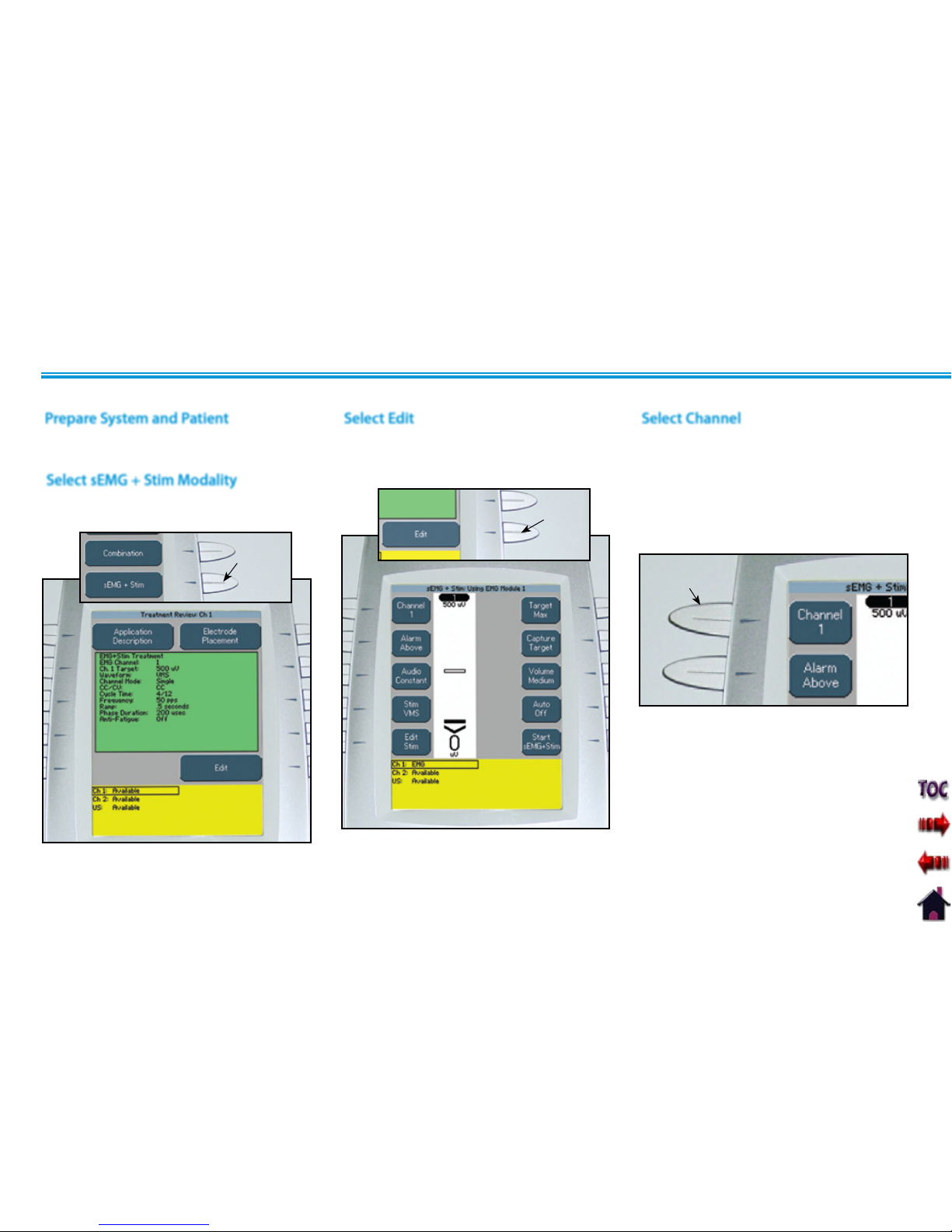
Vectra Genisys® Therapy System
73
OPERATION
Prepare Therapy System and patient. Refer
to pages 37 through 40.
Prepare System and Patient
Press the sEMG + Stim button on the Home
screen.
Select sEMG + Stim Modality
sEMG+STIM
BUTTON
sEMG+STIM THERAPY SET UP (CONTINUED)
Select Edit
Press the Edit button on the Treatment
Review screen to edit sEMG + Stim
parameters as prescribed.
EDIT
BUTTON
Select Channel
Press the Channel button until the
prescribed channel is displayed in the icon.
Therapy System
Available selections are 1 or 2.
Channel 3/4 Electrotherapy Module
Available selections are 3 or 4.
CHANNEL
BUTTON
NOTE: The sEMG + Stim will not function
as a multi-channel modality. It
is designed for single channel
use only. However, it is available
to all electrotherapy channels.
Page 83

Vectra Genisys® Therapy System
74
OPERATION
ALARM
BUTTON
sEMG + STIM THERAPY SET UP (CONTINUED)
AUDIO
BUTTON
Select Stim Waveform
Press the Stim button.
STIM
BUTTON
UP ARROW
BUTTON
DOWN ARROW
BUTTON
ACCEPT
AND
RETURN
ARROW
BUTTON
Press the Up and Down Arrow buttons until
the prescribed waveform is highlighted.
Press the Accept and Return Arrow button.
Set Alarm
Set the alarm trigger in relation to the
target by pressing the Alarm button until
the desired selection is displayed in the
Alarm icon.
The available selections are:
Above- Alarm sounds when a muscle
contraction surpasses the target.
Target- Alarm sounds when a muscle
contraction reaches the target.
Below- Alarm sounds when a muscle
contraction is below the target.
NOTE: If Volume is Off, no alarm will be
heard.
Set Audio Type
Audio sets the type of sound heard when
the muscle contraction reaches the Alarm
setting.
Press the Audio button until the desired
audio type is displayed in the Audio icon.
The available selections are:
Constant- Continuous sound. ________
Pulsed- Fast, short beeps. . . . . . . . . . . . . . .
Dynamic- Slow, long beeps. _ _ _ _ _ _
NOTE: If volume is Off, no Audio type will
be heard.
Page 84

Vectra Genisys® Therapy System
75
OPERATION
Refer to page 45 for Stim Editing
procedures.
After editing is complete, press the Back
button.
NOTE: Stim treatment time is fixed and
cannot be changed.
sEMG + STIM THERAPY SET UP (CONTINUED)
TARGET
BUTTON
CAPTURE TARGET
BUTTON
BEGIN CAPTURE
BUTTON
Edit Stim
Press the Edit Stim button.
EDIT STIM BUTTON
BACK
BUTTON
Three options are available for setting the
sEMG modality target:
Max- Maximum of muscle contractions in
10 seconds.
Avg- Average of maximums achieved in
15 seconds of muscle contractions.
Manual- Set Target manually.
Press the Target button until the prescribed
target option is displayed in the Target icon.
Select Target Option Setting Max Target
Make certain Target Max is displayed in the
Target icon.
Press the Capture Target button. Have the
patient begin contracting the muscle and
press the Begin Capture button. Patient
should contract the muscle as hard as
possible during the preset 10 second
contraction period.
NOTE: The capture may be stopped by
pressing the End Capture button.
The System will then select the
maximum contraction level
achieved during the preset
10 second contraction period.
Page 85

Vectra Genisys® Therapy System
76
OPERATION
sEMG + STIM THERAPY SET UP (CONTINUED)
During the preset 10 second contraction
period, the Therapy System captures
and retains the maximum level of the
contraction the patient performed, then
automatically displays the Adjust sEMG
Target screen.
Use the Up and Down Arrow buttons to
adjust the Target percentage displayed at
the bottom of each channel column.
Press the Accept and Return Arrow button
to set the Target.
UP ARROW
BUTTON
ACCEPT AND
RETURN ARROW
BUTTON
DOWN ARROW
BUTTON
Setting Avg Target
Make certain Target Avg is displayed in the
Target icon.
Press the Capture Target button. Have the
patient begin contracting and releasing the
muscle. Press the Begin Capture button.
The patient should contract and release the
muscle as many times as possible during
the preset 15 second contraction period.
CAPTURE TARGET
BUTTON
BEGIN CAPTURE
BUTTON
During the preset 15 second contraction
period, the Therapy System captures and
retains the average maximum level of the
contractions the patient performed, then
automatically displays the Adjust sEMG
Target screen.
Use the Up and Down Arrow buttons to
adjust the Target percentage displayed at
the bottom of each channel column.
Press the Accept and Return Arrow button
to set the Target.
UP ARROW
BUTTON
ACCEPT AND
RETURN ARROW
BUTTON
DOWN ARROW
BUTTON
Page 86

Vectra Genisys® Therapy System
77
OPERATION
sEMG + STIM THERAPY SET UP (CONTINUED)
Press the Up and Down Arrow buttons to
adjust Target to prescribed level.
Press the Accept and Return Arrow button.
DOWN ARROW
BUTTON
ACCEPT AND
RETURN
ARROW BUTTON
UP ARROW
BUTTON
Make certain Target Manual is displayed in
the Target icon.
Press the Adjust Target button.
Setting Manual Target
ADJUST TARGET
BUTTON
Set Volume
Press Volume button until the desired
volume level is displayed in the Volume
icon.
The available volume levels are Low,
Medium, High, and Off.
VOLUME
BUTTON
NOTE: If Volume is Off, no alarm will
be heard when contraction reaches
the target setting.
Page 87
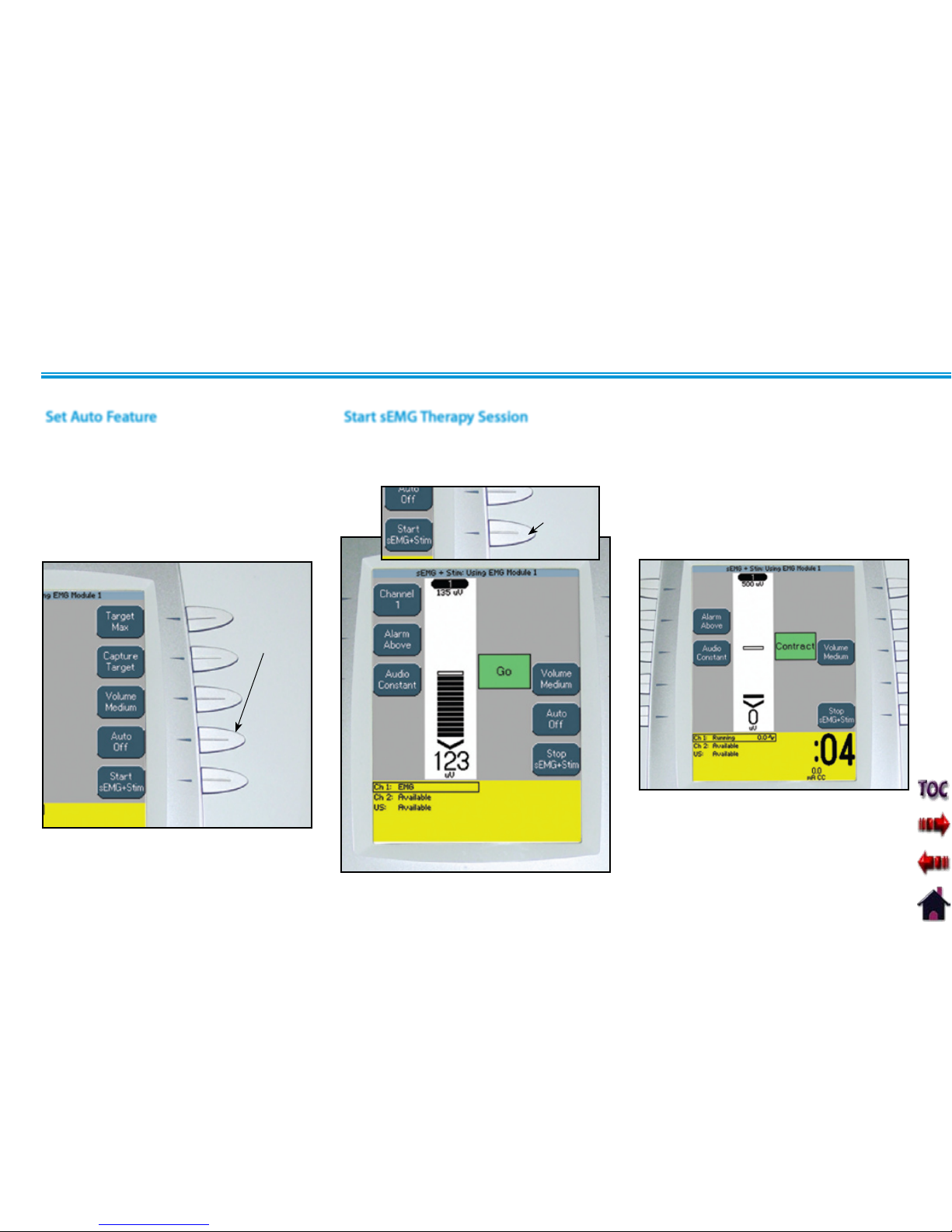
Vectra Genisys® Therapy System
78
OPERATION
sEMG + STIM THERAPY SET UP (CONTINUED)
Start sEMG Therapy Session
Have patient perform contractions as
prescribed.
When the contraction reaches the target,
the alarm will sound, the screen will change
and Stim will begin. The patient should
hold the contraction throughout the short
period of Stim.
After all parameters for sEMG and Stim have
been completed, press the Start sEMG +
Stim button.
START SEMG+STIM
BUTTON
NOTE: The Stim Intensity may be adjusted
only during the Stim portion of
the sEMG + Stim therapy session.
Set Auto Feature
The sEMG + Stim Auto feature is designed
to work in conjunction with the Target
settings. When On, the Auto feature will
automatically adjust the maximum target
as the patient fatigues.
Press the Auto button until Off or On is
displayed in the Auto icon.
AUTO
BUTTON
Page 88

Vectra Genisys® Therapy System
79
OPERATION
NOTE: Refer to pages 80 through 89 for
Patient Data Card set up and use.
The sEMG Data Card cannot be used to
save session parameters.
sEMG data, from an sEMG + Stim therapy
session, cannot be recorded to a sEMG Data
Card or Patient Data Card.
sEMG + STIM THERAPY SET UP (CONTINUED)
Stopping Stim
Stim may be stopped at any time during
the session by pressing the Stop sEMG +
Stim button.
STOP SEMG+STIM
BUTTON
Press the Stop button. The Completed
Treatment Review screen will display.
Stopping Therapy Session
Stim may be restarted at any time during
the session by pressing the Start sEMG +
Stim button.
NOTE: With Stim Off, the sEMG portion of
the session may continue.
After Stim is complete, the screen will
change and the patient should relax the
contraction.
After the Relax period is complete the
screen will change to Go.
Repeat the process throughout the
prescribed treatment time or until the
patient is fatigued.
Page 89

Vectra Genisys® Therapy System
80
OPERATION
PATIENT DATA CARD SET UP OF NEW CARD
The Vectra Genisys Therapy System incorporates a Patient Data Card reading and recording device that allows transfer of patient therapy
data from the system to the card for reviewing patient modality and pain profile information. Information may be transferred to a PC via the
optional Patient Data Management System. The PC software is designed to allow easy access to patient data and printing of reports as well as
adding session notes to the Patient Data Card.
The reading and recording device allows storage and recall of the following patient session data onto the Patient Data Card: Therapy Session
Parameters, Electrode Placement, Pain Map, Numeric Pain Scale or Visual Pain Scale, and Session Notes (stored on card via PC only). Each
Patient Data Card can store multiple sessions and each session can be recalled on the Vectra Genisys Therapy System.
With new Patient Data Card inserted in
the system, press the Save to Patient Card
button.
Insert New Patient Data Card
Insert a new Patient Data Card into the
system access port as shown below. The
Therapy System will automatically format
the new Patient Data Card and a verification
message will appear.
Press any button to continue.
PRESS ANY BUTTON
TO CONTINUE
INSERT NEW
PATIENT DATA CARD
Set up the patient's prescribed treatment.
Refer to the appropriate area of this manual
for modality set up.
Administer treatment as prescribed. When
treatment is complete, the Treatment
Review screen will be visible.
Set Up Treatment
Set Up of New Patient Data Card
SAVE TO
PATIENT CARD
BUTTON
General Information
Page 90

Vectra Genisys® Therapy System
81
OPERATION
PATIENT DATA CARD SET UP OF NEW CARD (CONTINUED)
Select the row of alpha or numeric
characters desired by pushing the button
beside the corresponding row. Select the
desired character in the row by pressing
the row button until the desired letter is
framed.
Enter Patient ID
SELECT ROW AND CHARACTERS
When the desired character is framed, press
the Accept and Return Arrow button. The
character selected will display in the top of
the screen and the cursor will advance to
the next position.
To move back a character, press the Left
Arrow button.
To delete a character, press the Left Arrow
button until the character to be deleted is
framed. Press the Delete button.
To discard entire entry, press the Back
button.
Repeat this procedure until the desired
Patient ID is entered.
After Patient ID is entered, press the Save
button.
CHARACTER
DISPLAYED
ACCEPT AND RETURN
ARROW BUTTON
LEFT
ARROW
BUTTON
NOTE: To add a space, select the area to
the left of the letter A.
SAVE
BUTTON
Page 91

Vectra Genisys® Therapy System
82
OPERATION
PATIENT DATA CARD SET UP OF NEW CARD (CONTINUED)
The following information uses an IFC
Treatment as an example. Electrode
Placement procedures for all modalities are
performed in the same basic fashion.
Press the Electrode Placement button.
NOTE: When Ultrasound is the modality,
only the Side button is available.
Access Electrode Placement
ELECTRODE PLACEMENT BUTTON
Electrode Placement Set Up
PAD
BUTTON
CHAN
BUTTON
SIDE
BUTTON
SIZE
BUTTON
Press the Up, Down, Left and Right Arrow
buttons to position the selected electrode
as close to the actual treatment location as
possible.
Press the Pad button to select the other
electrode. Repeat above procedure for
electrode positioning.
If applicable, press the Chan button to
select another channel and repeat above
procedures.
After positioning the electrodes, press the
Accept and Return Arrow button.
Electrode Placement
ACCEPT AND RETURN
ARROW BUTTON
ELECTRODES
POSITIONED
Press the Pad button to select the Red (+) or
Black (-) electrode.
Press the Chan button to select Channel 1
or Channel 2.
Press the Side button to select Front, Back,
Left, or Right of the body graphic.
Press the Size button until desired electrode
size is displayed. If electrode desired is not
listed, select Other.
Page 92

Vectra Genisys® Therapy System
83
OPERATION
PATIENT DATA CARD SET UP OF NEW CARD (CONTINUED)
Press the Pain Map button to select
the body area of the associated pain as
described by the patient.
Access Pain Map
PAIN MAP BUTTON
Select Pain Type
Press the Pain Type button until the
desired description is displayed in the Pain
Type icon.
PAIN TYPE
BUTTON
Add Pain Locations
Press the Add button. The Add Pain Map
window will display.
ADD
BUTTON
NOTE: A maximum of eight Pain Locations
may be selected.
Page 93

Vectra Genisys® Therapy System
84
OPERATION
PATIENT DATA CARD SET UP OF NEW CARD (CONTINUED)
Select Location of Pain
Press the Up and Down Arrow buttons to
move the Pain Locator to the area of the
body where the pain is located.
Press the Accept and Return Arrow button.
The Pain Map window will display.
Press the Edit button on the Pain Map
window.
UP AND DOWN
ARROW BUTTONS
PAIN
LOCATOR
ACCEPT AND RETURN
ARROW BUTTON
Press the Add button to continue selecting,
in sequence, the radiating path of the pain
using the above procedure.
Up to eight pain locations may be selected.
ADD
BUTTON
After all desired Pain Locations have been
made, press the Back button.
BACK
BUTTON
Editing Pain Locations
EDIT
BUTTON
Press the Edit Next button to highlight the
Pain Location to be edited.
Use the Up and Down Arrow buttons to
relocate the selected Pain Location.
Press the Accept and Return Arrow button.
Repeat until all editing is complete, then
press the Back button.
UP AND DOWN
ARROW BUTTONS
ACCEPT AND RETURN
ARROW BUTTON
EDIT NEXT
BUTTON
Page 94

Vectra Genisys® Therapy System
85
OPERATION
PATIENT DATA CARD SET UP OF NEW CARD (CONTINUED)
Press the Delete button on the Pain Map
window.
Deleting Pain Locations
DELETE
BUTTON
Use the Up and Down Arrow buttons to
highlight the Pain Location to be deleted.
Press the Delete button.
Press the Accept and Return Arrow button.
Repeat until all editing is complete, then
press the Back button.
UP AND DOWN
ARROW BUTTONS
ACCEPT AND RETURN
ARROW BUTTON
DELETE
BUTTON
Select the desired Pain Scale by pressing the
corresponding button.
Press the Left and Right Arrow buttons to
adjust the Pain Scale to the level the patient
is experiencing.
The Vectra Genisys Therapy System incorporates two internationally recognized Pain
Scales: one, VAS (Visual Analog Scale) has no indicator marks and, two, Numeric Scale
(indicated 1 through 10). Use either of these for describing the amount of pain the patient
is experiencing. When either pain scale is set, the other will automatically set to the
corresponding level.
NOTE:
Numeric Pain Scale illustrated.
Pain Scales
Select Pain Scale
NUMERIC PAIN
SCALE BUTTON
VISUAL PAIN
SCALE BUTTON
Adjust Pain Scale
After the desired level is achieved, press the
Accept and Return Arrow button.
ACCEPT AND RETURN
ARROW BUTTON
RIGHT
ARROW
BUTTON
LEFT
ARROW
BUTTON
Page 95

Vectra Genisys® Therapy System
86
OPERATION
After all desired session data has been
entered in the Patient Data Card screens,
press the Save to Patient Card button. A
message will appear stating the data has
been saved to the Patient Data Card.
Press any button.
PATIENT DATA CARD SET UP OF NEW CARD (CONTINUED)
Save to Patient Data Card
SAVE TO PATIENT
CARD BUTTON
After pressing any button, the Completed
Treatment Review screen will display.
Press the Home button.
Remove the Patient Data Card for filing with
patient records.
The Patient Data Card can also be used with
the optional Patient Data Management
System.
Page 96

Vectra Genisys® Therapy System
87
OPERATION
EXISTING PATIENT DATA CARD USE
Insert Existing Patient Data Card
Insert the Patient Data Card assigned to the
patient receiving treatment into the system
access port as shown below.
INSERT EXISTING
PATIENT DATA CARD
PATIENT CARD
BUTTON
Access Patient Data Card
Press the Patient Card button to access
Patient Data Card.
Select the date of the treatment session
desired using the Up and Down Arrow
buttons until date desired is highlighted.
UP ARROW
BUTTON
DOWN ARROW
BUTTON
View Patient Data Card
Press the corresponding button beside the
Patient Data to be viewed.
NOTE: No Session Notes will be
available unless the optional
Patient Data Management System
was utilized to enter Session Notes
onto the Patient Data Card.
Page 97

Vectra Genisys® Therapy System
88
OPERATION
Refer to pages 32-35 for Electrotherapy
patient preparation, select electrodes, and
secure electrodes. Refer to page 36 for
Ultrasound patient preparation.
Press the Up and Down Arrow buttons to
highlight the desired treatment date and
time.
Press the View Treat. button.
Press Start New Treatment button.
EXISTING PATIENT DATA CARD USE (CONTINUED)
Starting a New Treatment from Patient
Data Card
VIEW TR EAT.
BUTTON
START NEW
TREATMENT
BUTTON
Set intensity by rotating the Intensity Control
Knob to the prescribed level.
Set Intensity
INTENSITY
DISPLAYED
Clockwise- Increases Intensity
Counterclockwise- Decreases Intensity
Intensity Knob Rotation
ROTATE
INTENSITY
KNOB
Connect Patient Interrupt Switch to the
Therapy System. Give Patient Interrupt
Switch to patient and explain that pressing
the Red button once pauses the therapy
session.
Optional Patient Interrupt Switch
CONNECT PATIENT
INTERRUPT SWITCH
PATIENT
INTERRUPT
SWITCH
If Patient Interrupt Switch is depressed, the
treatment will be paused and a message
will appear on the System screen.
Press any button to clear the message.
NOTE: If the Patient Interrupt Switch
is depressed a second time,
the message will clear from
the screen and the treatment
will remain paused.
Page 98

Vectra Genisys® Therapy System
89
OPERATION
Refer to page 28 for proper Patient Data
Card Erasing instructions.
EXISTING PATIENT DATA CARD USE (CONTINUED)
Start Treatment
Press the Start button to begin therapy
session.
Pause Treatment
Press the Pause button to pause therapy
session and maintain remaining time. To
resume treatment, press the Pause button
again.
Stop Treatment
To Stop treatment, press the Stop button
once. Treatment will stop and the
Completed Treatment Review screen will
display.
Erasing Patient Data Card
START
BUTTON
PAUSE
BUTTON
STOP BUTTON
Page 99

Vectra Genisys® Therapy System
90
OPERATION
The Vectra Genisys Therapy System incorporates a sEMG Data Card that allows the recording of sEMG data from sEMG therapy sessions.
After recording the sEMG data, it can be imported, saved to, and viewed through a Windows® PC equipped with the optional Patient Data
Management System. The Patient Data Management System software and Card Reader are designed to allow importing and easy access to
the sEMG data, printing of reports, adding session notes, and adding other sEMG specific information to the sEMG data through a Windows®
PC.
The Therapy System sEMG Data Card allows recording only of the sEMG Data. No sEMG Data may be recorded from the PC and saved to the
sEMG Data Card for use in the Therapy System. However, the sEMG session parameters may be saved to a Patient Data Card (refer to pages 80
through 89) and recalled in the Therapy System.
Each time an existing sEMG Data Card is used for another sEMG therapy session, the existing sEMG data is overwritten with the new session
data.
It is recommended that each patient be assigned a sEMG Data Card. sEMG Data cannot be saved or recorded to the Patient Data Card.
NOTE: This section applies only to models capable of supporting the functions of the sEMG module.
SET UP OF NEW sEMG DATA CARD
General Information
Page 100

Vectra Genisys® Therapy System
91
OPERATION
Prepare Therapy System and patient. Refer
to pages 37 through 40.
Set up the patient's prescribed sEMG
therapy session. Refer to pages 53
through 60 of this manual for sEMG
modality set up.
Press the Setup sEMG Card button.
SET UP OF NEW sEMG DATA CARD (CONTINUED)
Insert New sEMG Data Card
Insert a new sEMG Data Card into the
system access port as shown below. The
Therapy System will automatically format
the new sEMG Data Card and a verification
message will appear.
Press any button to continue.
PRESS ANY BUTTON
TO CONTINUE
INSERT NEW sEMG DATA CARD
Set Up sEMG Therapy Session
Prepare System and Patient
SETUP sEMG CARD
BUTTON
Select the row of alpha or numeric
characters by pushing the button beside
the corresponding row. Select the desired
character in the row by pressing the row
button until the desired letter is framed.
Enter Patient ID
SELECT ROW AND CHARACTERS
 Loading...