

Page 1

Supplied by EME Services Ltd
User Manual
Operation & Installation
Instructions for:
Intelect Shortwave 100
REF 1602
Intelect Shortwave 100 (Canada)
REF 1604
Page 2
TABLE OF CONTENTS
W
Supplied by EME Services Ltd
Intelect® Shortwave 100
FOREWORD . . . . . . . . . . . . . . . . . . . . . . . . . . . . . . . . . . . . . . . . . . . 1
Product Description. . . . . . . . . . . . . . . . . . . . . . . . . . . . . . . . . . 1
General Information . . . . . . . . . . . . . . . . . . . . . . . . . . . . . . . . . 2
SAFETY INSTRUCTIONS . . . . . . . . . . . . . . . . . . . . . . . . . . . . . . . . 4
Precautionary Definitions . . . . . . . . . . . . . . . . . . . . . . . . . . . . 4
Cautions . . . . . . . . . . . . . . . . . . . . . . . . . . . . . . . . . . . . . . . . . . . .
Warnings . . . . . . . . . . . . . . . . . . . . . . . . . . . . . . . . . . . . . . . . . . . . 6
Dangers . . . . . . . . . . . . . . . . . . . . . . . . . . . . . . . . . . . . . . . . . . . . 10
Personal Safety . . . . . . . . . . . . . . . . . . . . . . . . . . . . . . . . . . . . . 12
Protection of the Unit . . . . . . . . . . . . . . . . . . . . . . . . . . . . . . . 14
ABOUT SHORTWAVE DIATHERMY . . . . . . . . . . . . . . . . . . . . . 16
Overview. . . . . . . . . . . . . . . . . . . . . . . . . . . . . . . . . . . . . . . . . . . 16
Pulsed Shortwave Diathermy - Introduction . . . . . . . . . . 16
INDICATIONS. . . . . . . . . . . . . . . . . . . . . . . . . . . . . . . . . . . . . . . . . 17
General . . . . . . . . . . . . . . . . . . . . . . . . . . . . . . . . . . . . . . . . . . . . 17
CONTRAINDICATIONS . . . . . . . . . . . . . . . . . . . . . . . . . . . . . . . . 20
General . . . . . . . . . . . . . . . . . . . . . . . . . . . . . . . . . . . . . . . . . . . . 20
ADDITIONAL PRECAUTIONS . . . . . . . . . . . . . . . . . . . . . . . . . . 24
General . . . . . . . . . . . . . . . . . . . . . . . . . . . . . . . . . . . . . . . . . . . . 24
SETUP . . . . . . . . . . . . . . . . . . . . . . . . . . . . . . . . . . . . . . . . . . . . . . . 26
Unpacking the Unit . . . . . . . . . . . . . . . . . . . . . . . . . . . . . . . . . 26
Inspection. . . . . . . . . . . . . . . . . . . . . . . . . . . . . . . . . . . . . . . . . . . 26
Requirements for Installation. . . . . . . . . . . . . . . . . . . . . . . . 27
Requirements for the Installation Location. . . . . . . . . . . . 27
NOMENCLATURE . . . . . . . . . . . . . . . . . . . . . . . . . . . . . . . . . . . . . 28
Front View. . . . . . . . . . . . . . . . . . . . . . . . . . . . . . . . . . . . . . . . . . 28
Rear View . . . . . . . . . . . . . . . . . . . . . . . . . . . . . . . . . . . . . . . . . . 29
5
User Interface . . . . . . . . . . . . . . . . . . . . . . . . . . . . . . . . . . . . . . 30
Software Symbols. . . . . . . . . . . . . . . . . . . . . . . . . . . . . . . . . . . 31
Accessories . . . . . . . . . . . . . . . . . . . . . . . . . . . . . . . . . . . . . . . . . 32
Capacitive Electrodes . . . . . . . . . . . . . . . . . . . . . . . . . . . . . . . . 32
Flexible Rubber Electrodes. . . . . . . . . . . . . . . . . . . . . . . . . . . 32
Monode (Drum) Electrode . . . . . . . . . . . . . . . . . . . . . . . . . . . 33
Diplode Electrode . . . . . . . . . . . . . . . . . . . . . . . . . . . . . . . . . . . 33
Indicator Discharge Tube . . . . . . . . . . . . . . . . . . . . . . . . . . . . 33
SPECIFICATIONS. . . . . . . . . . . . . . . . . . . . . . . . . . . . . . . . . . . . . . 34
Unit Specifications . . . . . . . . . . . . . . . . . . . . . . . . . . . . . . . . . . 34
Operating Data and Ratings. . . . . . . . . . . . . . . . . . . . . . . . . . 34
Software . . . . . . . . . . . . . . . . . . . . . . . . . . . . . . . . . . . . . . . . . . . . 35
Transport and Storage Conditions. . . . . . . . . . . . . . . . . . . . 35
Safety . . . . . . . . . . . . . . . . . . . . . . . . . . . . . . . . . . . . . . . . . . . . . . . 35
Applicator Specifications . . . . . . . . . . . . . . . . . . . . . . . . . . . . 36
Load Resistance and Applicator Spacing. . . . . . . . . . . . . . 36
Description of Device Markings . . . . . . . . . . . . . . . . . . . . . . 37
OPERATION . . . . . . . . . . . . . . . . . . . . . . . . . . . . . . . . . . . . . . . . . . 38
Description of Functions . . . . . . . . . . . . . . . . . . . . . . . . . . . . 38
i
Page 3
TABLE OF CONTENTS
Supplied by EME Services Ltd
Intelect® Shortwave 100
Introduction. . . . . . . . . . . . . . . . . . . . . . . . . . . . . . . . . . . . . . . . . 38
Applications. . . . . . . . . . . . . . . . . . . . . . . . . . . . . . . . . . . . . . . . . 38
Shortwave Diathermy in the
Capacitive (Dielectric) Field . . . . . . . . . . . . . . . . . . . . . . . . . . 39
Shortwave Diathermy in the Inductive Field . . . . . . . . . . 40
Installing the Applicators. . . . . . . . . . . . . . . . . . . . . . . . . . . . 41
Installing the Capacitive Electrodes . . . . . . . . . . . . . . . . . . 41
Installing the Monode (Drum) Electrode . . . . . . . . . . . . . . 43
Installing the Flexible Rubber Electrodes . . . . . . . . . . . . . 45
Preparing the Unit for Therapy. . . . . . . . . . . . . . . . . . . . . . . 46
Preparing the Patient for Therapy . . . . . . . . . . . . . . . . . . . . 47
Basic Operation. . . . . . . . . . . . . . . . . . . . . . . . . . . . . . . . . . . . . 48
Starting Therapy. . . . . . . . . . . . . . . . . . . . . . . . . . . . . . . . . . . . 49
Home Screen . . . . . . . . . . . . . . . . . . . . . . . . . . . . . . . . . . . . . . . . 49
Edit Treatment Screen . . . . . . . . . . . . . . . . . . . . . . . . . . . . . . . 49
Electrode Screen . . . . . . . . . . . . . . . . . . . . . . . . . . . . . . . . . . . . 50
Thermal Dosimetry . . . . . . . . . . . . . . . . . . . . . . . . . . . . . . . . . . 51
Quick Link Indications . . . . . . . . . . . . . . . . . . . . . . . . . . . . . . . 52
Starting Therapy from the Home Screen. . . . . . . . . . . . . . 52
Using the Indicator Discharge Tube . . . . . . . . . . . . . . . . . . 53
Stopping, Pausing, and Completing Therapy. . . . . . . . . . 54
Stopping Therapy Using the STOP Button . . . . . . . . . . . . 54
Stopping Therapy Using the Patient
Interrupt Cord . . . . . . . . . . . . . . . . . . . . . . . . . . . . . . . . . . . . . . . 54
Pausing Therapy . . . . . . . . . . . . . . . . . . . . . . . . . . . . . . . . . . . . . 55
Completing the Therapy Session . . . . . . . . . . . . . . . . . . . . . 55
Using Clinical Protocols . . . . . . . . . . . . . . . . . . . . . . . . . . . . . 56
Retrieving, Deleting, and Saving User Protocols. . . . . . . 58
Retrieving User Protocols . . . . . . . . . . . . . . . . . . . . . . . . . . . . 58
Deleting User Protocols. . . . . . . . . . . . . . . . . . . . . . . . . . . . . . 58
Saving New User Protocols. . . . . . . . . . . . . . . . . . . . . . . . . . . 59
Editing Existing User Protocols . . . . . . . . . . . . . . . . . . . . . . . 60
Using Clinical Resources - Educational Library . . . . . . . . 61
Anatomical Graphics Library . . . . . . . . . . . . . . . . . . . . . . . . . 61
Electrode Placement Library . . . . . . . . . . . . . . . . . . . . . . . . . 62
Diathermy Rationale . . . . . . . . . . . . . . . . . . . . . . . . . . . . . . . . . 64
Contraindications. . . . . . . . . . . . . . . . . . . . . . . . . . . . . . . . . . . . 64
Using Clinical Resources - Patient Card . . . . . . . . . . . . . . . 65
Patient Card . . . . . . . . . . . . . . . . . . . . . . . . . . . . . . . . . . . . . . . . . 65
Edit Pain Profile. . . . . . . . . . . . . . . . . . . . . . . . . . . . . . . . . . . . . . 66
Saving Treatments to the Patient Card. . . . . . . . . . . . . . . . 68
Erasing Patient Card . . . . . . . . . . . . . . . . . . . . . . . . . . . . . . . . . 69
Using Clinical Resources - Unit Settings. . . . . . . . . . . . . . . 70
Adding and Changing the Clinic Name . . . . . . . . . . . . . . . 70
Increasing and Decreasing the Unit Volume . . . . . . . . . . 70
Setting the Date and Time . . . . . . . . . . . . . . . . . . . . . . . . . . . 71
Resetting Unit Settings . . . . . . . . . . . . . . . . . . . . . . . . . . . . . . 71
Resetting Default Protocols . . . . . . . . . . . . . . . . . . . . . . . . . . 71
Changing Languages . . . . . . . . . . . . . . . . . . . . . . . . . . . . . . . . 72
Using the Applicators . . . . . . . . . . . . . . . . . . . . . . . . . . . . . . . 74
Using the Capacitive Electrodes . . . . . . . . . . . . . . . . . . . . . . 74
Using the Monode (Drum) Electrode . . . . . . . . . . . . . . . . . 75
ii
Page 4
TABLE OF CONTENTS
T
T
W
T
T
T
Supplied by EME Services Ltd
Intelect® Shortwave 100
Using the Flexible Rubber Electrode. . . . . . . . . . . . . . . . . . 76
Treatment Tips. . . . . . . . . . . . . . . . . . . . . . . . . . . . . . . . . . . . . . 78
Positioning the Electrodes . . . . . . . . . . . . . . . . . . . . . . . . . . . 78
Positioning of Electrodes - Edge Effect. . . . . . . . . . . . . . . . 78
Positioning of Electrodes - Edge Effect
and Metal Objects . . . . . . . . . . . . . . . . . . . . . . . . . . . . . . . . . . . 78
Positioning of Electrodes - Electrode
Constriction . . . . . . . . . . . . . . . . . . . . . . . . . . . . . . . . . . . . . . . . . 79
Positioning of Electrodes - Normal Cases . . . . . . . . . . . . . 80
Setting the Electrode - Skin Distance . . . . . . . . . . . . . . . . . 81
Dosage Levels According to Schliephake . . . . . . . . . . . . . 82
TROUBLESHOOTING . . . . . . . . . . . . . . . . . . . . . . . . . . . . . . . . . . 83
Errors . . . . . . . . . . . . . . . . . . . . . . . . . . . . . . . . . . . . . . . . . . . . . . 83
Error Codes and Descriptions . . . . . . . . . . . . . . . . . . . . . . . . 83
Using the Indicator Discharge Tube . . . . . . . . . . . . . . . . . . 84
MAINTENANCE . . . . . . . . . . . . . . . . . . . . . . . . . . . . . . . . . . . . . . . 85
Maintaining the Intelect Shortwave 100 . . . . . . . . . . . . . . 85
Routine Maintenance . . . . . . . . . . . . . . . . . . . . . . . . . . . . . . . . 85
Cleaning and Disinfection. . . . . . . . . . . . . . . . . . . . . . . . . . . . 85
Safety Inspections . . . . . . . . . . . . . . . . . . . . . . . . . . . . . . . . . . . 85
Service . . . . . . . . . . . . . . . . . . . . . . . . . . . . . . . . . . . . . . . . . . . . . . 87
Warranty Repair/Out of Service Repair. . . . . . . . . . . . . . . . 87
ACCESSORIES . . . . . . . . . . . . . . . . . . . . . . . . . . . . . . . . . . . . . . . . 88
Standard Accessories. . . . . . . . . . . . . . . . . . . . . . . . . . . . . . . . 88
Optional Accessories . . . . . . . . . . . . . . . . . . . . . . . . . . . . . . . . 88
WARRANTY . . . . . . . . . . . . . . . . . . . . . . . . . . . . . . . . . . . . . . . . . . 89
APPENDIX A EMC TABLES . . . . . . . . . . . . . . . . . . . . . . . . . . . . 90
Table 1: Guidance and Manufacturer’s Declaration–
Electromagnetic Emissions . . . . . . . . . . . . . . . . . . 90
Table 2: Guidance and Manufacturer’s Declaration–
Electromagnetic Immunity . . . . . . . . . . . . . . . . . . 91
Table 3: Recommended Separation Distances
between Portable and Mobile RF
Communications Equipment and the
Intelect Shortwave 100. . . . . . . . . . . . . . . . . . . . . . 93
iii
Page 5

FOREWORD
Supplied by EME Services Ltd
This manual has been written for the owners and operators of the Intelect® Shortwave 100 system. It contains general information on the
operation, precautionary practices, and maintenance information. In order to maximize use, efficiency, and the life of your unit, please read
this manual thoroughly and become familiar with the controls, as well as the accessories, before operating the unit. This manual contains
general safety, operating, maintenance, and care instructions for the owners and operators of the Intelect Shortwave 100 system.
Specifications put forth in this manual were in effect at the time of publication. However, owing to Chattanooga Group's policy of
continual improvement, changes to these specifications may be made at any time without obligation on the part of Chattanooga Group.
Before administering any treatment to a patient, the user of this equipment should read, understand, and follow the information contained
in this manual for each mode of treatment available, as well as the indications, contraindications, warnings, and precautions. Consult other
resources for additional information regarding the application of shortwave diathermy.
Intelect® Shortwave 100
Product Description
The Intelect Shortwave 100 utilizes both inductive and capacitive electrodes to administer the clinical application of oscillating
electromagnetic energy in the radio frequency of 27.12 megahertz to treat a wide variety of orthopedic and physiotherapeutic conditions.
Diathermy generates deep heat within body tissues to increase circulation, decrease pain, decrease inflammation, increase ROM, influence
muscle tone, and facilitate the sub acute healing phase.
Stay current with the latest clinical developments in the field of shortwave diathermy. Observe all applicable precautionary measures for
treatment.
Keep informed on appropriate indications and contraindications for the use of shortwave diathermy.
This equipment is to be used by, and sold to, a trained clinician only under the prescription and supervision of a licensed
practitioner.
©2009 Encore Medical, L.P. and its affiliates, Austin, Texas, USA. Any use of editorial, pictorial, or layout composition of this publication without express written consent from
Chattanooga Group of Encore Medical, L.P. is strictly prohibited. This publication was written, illustrated, and prepared for print by Chattanooga Group of Encore Medical, L.P.
Certain portions of this manual have been reproduced with the consent of gbo Medizintechnik AG.
1
Page 6

FOREWORD
Supplied by EME Services Ltd
Intelect® Shortwave 100
GENERAL INFORMATION
The Intelect Shortwave 100 unit and the accompanying components and individual elements fulfill, as a unit, the currently valid safety
standards and comply with the stipulations of IEC 60601-1 and the medical products regulations.
The unit and its external components (accessory elements) are safe if used properly and in compliance with the explanations and
instructions provided in this documentation. Nevertheless, the unit or its external components can pose dangers. Therefore, we urgently
recommend that anyone operating the shortwave diathermy unit become aware of the potential dangers of the unit and its external
components before beginning work.
Please read and observe all safety instructions in this operating manual.
The following features are available on the Intelect Shortwave 100 unit:
Clear Touch Screen LCD
Allows the operator to select an option on the screen by simply touching it. Guides the operator through the setup process providing
continuous feedback about treatment settings. Gives the operator optimal visibility during attended procedures. Allows the operator to
turn on the unit simply by pressing the LCD.
Clinical Protocols™
An efficient approach for setting up a treatment using preset parameters.
Thermal Dosimetry
Allows the operator to set up a treatment using the four treatment dosages according to Schliephake (see page 82).*
*Low and Reed (1990)
2
Page 7

FOREWORD
Supplied by EME Services Ltd
Intelect® Shortwave 100
GENERAL INFORMATION CONTINUED
Quick Link Indications
The Intelect Shortwave 100 incorporates a unique Quick Link Indications section which allows the user to select specific clinical indications
and apply the most common therapy for the Indication selected. All modalities are editable, in their normal editing fashion, in order to
customize the treatment for each patient’s prescribed therapy.
User Protocols
User protocols allow you to set, save, and change the parameters of each program (protocol) in order to tailor it to meet your patients’
specific needs. You may create up to 200 user protocols.
Automatic Tuning
The Intelect Shortwave 100 has been programmed to automatically regulate the power between the electrodes and the patient.
Screen Saver
The screen saver function acts like any other screen saver on a normal computer to reduce LCD screen burn-in. The unit will enter screen
saver mode after 10 minutes of inactivity. If the user presses the touch screen or any button on the User Interface, it will return to the Home
screen.
Realtime Clock
The Realtime Clock keeps track of date and time even when the unit is turned off or unplugged.
3
Page 8
SAFETY INSTRUCTIONS
Supplied by EME Services Ltd
Intelect® Shortwave 100
PRECAUTIONARY DEFINITIONS
The precautionary instructions found in this section and throughout this manual are indicated by specific symbols. Understand these
symbols and their definitions before operating this equipment. The definition of these symbols are as follows:
Explosion Hazard
Text with an “Explosion Hazard” indicator will explain
possible safety infractions if this equipment is used in the
Text with a “CAUTION” indicator will explain possible safety
infractions that could have the potential to cause minor to
moderate injury or damage to equipment.
Text with a “WARNING” indicator will explain possible safety
infractions that will potentially cause serious injury and
equipment damage.
presence of flammable anesthetics.
Dangerous Voltage
Text with a “Dangerous Voltage” indicator serves to inform
the user of possible hazards resulting in the electrical charge
delivered to the patient or operator in certain treatment
configurations.
Non-ionizing Electromagnetic Radiation
Text with a “Non-ionizing Electromagnetic Radiation"
indicator informs the user of possible hazards resulting
from elevated, potentially dangerous, levels of non-ionizing
radiation.
Text with a “DANGER” indicator will explain possible safety
infractions that are imminently hazardous situations that would
result in death or serious injury.
Refer to Instruction Manual/Booklet
NOTE: Throughout this manual, “NOTE” may be found. These
Notes are helpful information to aid in the particular area
or function being described.
4
Page 9

SAFETY INSTRUCTIONS
Supplied by EME Services Ltd
Intelect® Shortwave 100
Read• , understand, and practice the precautionary operating
instructions. Know the limitations and hazards associated with using
any shortwave diathermy device. Observe the precautionary and
operational decals placed on the unit.
DO NOT operate the Intelect Shortwave 100 in conjunction with any
•
other devices.
DO NOT operate this unit in an environment where other devices
•
are being used that intentionally radiate electromagnetic energy
in an unshielded manner. Portable and mobile RF communications
equipment can affect medical electrical equipment.
The unit should be routinely checked before each use to determine
•
that all controls function normally, especially that the output
control does properly adjust the intensity of the shortwave
diathermy power output in a stable manner. Also, determine that
the treatment time control does actually terminate shortwave
diathermy power output when the timer reaches zero.
DO NOT use sharp objects such as a pencil point or ballpoint pen to
•
operate the buttons on the control panel as damage may result.
This unit should be transported and stored in temperatures
•
between -40 °C and 70 °C (-40 °F and 158 °F) to prevent damage to
the unit or its components.
Handle shortwave diathermy accessories with care. Inappropriate
•
handling of the accessories may adversely affect their characteristics.
Inspect cables, electrodes, associated connectors, and accessories •
before each use. To test the Patient Interrupt Cord, follow the
procedures listed in "Stopping Therapy Using the Patient Interrupt
Cord" on page 54.
Ex
nal conductive material should be removed from the
ter
•
immediate treatment area.
Do not use accessories other than those supplied with the unit, or
•
recommended by Chattanooga Group. The safety of other products
has not been established, and their use could result in injury to the
patient and degrade minimum safety.
Disconnect the power supply cord before removing covers on
•
this equipment. Refer the servicing of this unit to qualified service
personnel.
This equipment has an output that is capable of producing a
•
physiological effect.
Grounding reliability can only be achieved when the equipment is
•
connected to an equivalent receptacle marked "Hospital Only" or
"Hospital Grade."
Medical electrical equipment needs special precautions regarding
•
EMC and needs to be installed and put into service according to the
EMC information provided in this manual.
5
Page 10

SAFETY INSTRUCTIONS
Supplied by EME Services Ltd
Intelect® Shortwave 100
This unit generates, uses, and can radiate radio frequency energy •
and, if not installed and used in accordance with the instructions,
may cause harmful interference to other devices in the vicinity.
However, there is no guarantee that interference will not occur in
a particular installation. Harmful interference to other devices can
be determined by turning this equipment on and off. Try to correct
the interference using one or more of the following: reorient or
relocate the receiving device, increase the separation between
the equipment, connect the equipment to an outlet on a different
circuit from that to which the other device(s) are connected, and
consult the factory field service technician for help.
Medical devices that are to be used within
• 12 meters of the
Intelect Shortwave 100 should have an electromagnetic site survey
completed. See NOTE 2 on page 92 for more information.
T
mine the distance of separation for all equipment operating
o deter
•
near the Intelect Shortwave 100, consult the EMC tables applicable
to the other equipment. If the distance cannot be determined, make
certain that the other equipment is operated from a distance of no
less than 12 meters.
This equipment is to be used by, and sold to, a trained clinician only
•
under the prescription and supervision of a licensed practitioner.
Since • relatively high powers are used, there is the possibility of
producing shock, localized burns, and cataracts if the patient is
unaware of the heat due to reduced thermal sensation, or if the
patient does not know what to expect during treatment.
Improper installation, operation or maintenance of the shortwave
•
diathermy system may result in malfunctions of this unit or other
devices.
In case of display failure or other obvious defects, switch the unit off
•
immediately by means of the power switch, disconnect the power
cord from the power outlet, and notify a certified service technician.
Be aware that some synthetics and plastics, though assumed to be
•
non-conductive, may be heated by shortwave diathermy.
Adjustments or replacement of components may result in the
•
equipment failing to meet the requirements for interference
suppression.
If the unit cannot be installed immediately after delivery, the unit and
•
its external components or accessory elements must be stored in
their original packaging in a dry place.
Do not store or operate the unit in a dusty environment.
•
Do not cross cables.•
Keep all electrodes, accessories, and their cords separated during •
treatment by using the cable clips located on the side of the arm
extenders. Electrodes or their cords in contact with each other during
treatment could result in improper stimulation, skin burns, or damage
to the cord or electrode.
6
Page 11

SAFETY INSTRUCTIONS
Supplied by EME Services Ltd
Intelect® Shortwave 100
Do not lean on or hold the cables during treatment. •
Keep all line cords away from the diathermy unit cables. Do not •
store or coil line cords where they can come close to the cables on
an operating shortwave diathermy unit.
This equipment is not designed to prevent the ingress of water
•
or liquids. Ingress of water or liquids could cause malfunction of
internal components of the system and therefore create a risk of
injury to the patient.
Care must be taken when operating this unit adjacent to or stacked
•
with other equipment. If adjacent or stacked use is necessary,
the Intelect Shortwave 100 should be observed to verify normal
operation in the configuration in which it will be used. Potential
electromagnetic or other interference could occur to this or other
equipment. Try to minimize this interference by not using other
equipment in conjunction with it.
Use only accessories that are specially designed for this unit. Do
•
not use accessories manufactured by other companies on this
unit. Chattanooga Group is not responsible for any consequence
resulting from using products manufactured by other companies.
The use of other accessories or cables (other than those specified)
may result in increased emissions or decreased immunity of this unit.
Metal in treatment area will provide low impedance paths to the •
induced radio frequency current, producing local heating and
the possibility of burning. In particular, treatment should never be
given in the area of metal implants. Also, metal jewelry, buckles, cell
phones, etc must be removed.
Use of controls or adjustments or performance of procedures other
•
than those specified herein may result in hazardous exposure to
shortwave diathermy energy.
Make certain that the unit is electrically earthed by connecting
•
only to a earthed electrical service receptacle, conforming to the
applicable national and local electrical codes.
This device should be kept out of the reach of children.
•
Induction field electrodes that are operated without a patient could •
be destroyed due to overheating.
Make certain that the electrode arms and arm extenders are locked
•
firmly into place during shortwave diathermy therapy using the front
and rear handwheels to prevent unintentional movement. See page
28 for the nomenclature of the unit.
D
o not leav
•
therapy.
e patient unattended during shortwave diathermy
7
Page 12

SAFETY INSTRUCTIONS
Supplied by EME Services Ltd
Intelect® Shortwave 100
Remove the electrode applicator by pulling the cable connector only. •
DO NOT remove by pulling the cable.
To remove the cable from the applicator, make certain the power
•
is off. While the electrode applicator is being supported by the
electrode arm, hold the electrode while removing the cable to
prevent the electrode from dropping to the floor.
Tighten arms so that they do not move during therapy.
•
Observe the patient and the position of the arms at all times during •
therapy.
Inform the patient that the arms are not supposed to move during
•
therapy.
Before using the unit, verify the patient is not in contact with the unit,
•
the electrode connection cable, the electrodes, or other devices or
metal objects.
In the event that an Error message or Warning appears beginning •
with a 2 or 3, immediately stop all use of the unit and contact the
dealer or Chattanooga Group for service. Errors and Warnings in
these categories indicate an internal problem with the unit that
must be tested by Chattanooga Group or a Field Service Technician
certified by Chattanooga Group before any further operation or use
of the system.Use of a unit that indicates an Error or Warning in these
categories may pose a risk of injury to the patient, user, or extensive
internal damage to the system.
8
Page 13
SAFETY INSTRUCTIONS
Supplied by EME Services Ltd
Intelect® Shortwave 100
Do not administer shortwave diathermy to a patient who •
has had an implant in the past unless you are absolutely
certain that the implant and all leads in their entirety
have been removed. Note that the leads are often left
implanted after the implant is removed.
This unit generates non-ionizing radiation. Patients with
•
implanted electronic devices, such as cardiac pacemakers
and defibrillators, cochlear implants, bone growth
stimulators, deep brain stimulators, spinal cord stimulators,
and other nerve stimulators, must not be treated, even if
the device has been turned off.
The function of certain implanted devices (e.g.,
•
pacemakers) may be adversely affected during treatment
with shortwave diathermy. In case of doubt, the advice of
a licensed practitioner in charge of the patient should be
sought.
Shortwave diathermy should not be used on patients who
•
have any implanted metallic lead or any implanted system
that may contain a lead. Both the heating and non-heating
modes of operation pose a risk of tissue destruction. If
you are a licensed practitioner who implants or monitors
patients with leads or implanted systems with leads,
explain to the patient what diathermy is and stress that
they should not receive shortwave diathermy treatment. If
you are a licensed practitioner who uses diathermy in your
practice, be sure to ask patients about possible implants
before deciding to administer shortwave diathermy.
Other equipment, including patient connected devices, may •
be adversely affected when in close proximity to shortwave
diathermy equipment.
Patients should not be treated with shortwave diathermy when
•
they have reduced thermal sensitivity over the proposed area of
treatment, unless the physician in charge of the patient is notified.
Treatment should not be given through clothing, although it is
•
permissible to administer treatment through a dressing or plaster
in pulsed modes.
Remove hearing aids prior to treatment.
•
At average power levels above 5 W, patients should not be •
allowed to come into contact with conductive parts which are
earthed or which have an appreciable capacitance to earth and
which may provide unwanted pathways for the radio frequency
current. In particular, treatment must never be given with the
patient on metal framed couches, chairs, or beds. Do not use
conductive mattresses or mattress covers.
Before increasing the output in response to a report of inadequate
•
patient heating, verify that the cables are properly routed, spaced
correctly, and away from metal or grounded objects. The heating
effect may be misdirected and heating may be occurring in an
unwanted area.
Before each use, check the condition of the housing and the
•
insulation of the electrodes, electrode connection cable, and the
power supply cable. Also make sure that the cables have been
routed correctly.
9
Page 14

SAFETY INSTRUCTIONS
Supplied by EME Services Ltd
Intelect® Shortwave 100
If the unit is not • safe for operation, then it must be repaired
by certified service personnel and the operators must be
informed of the dangers posed by the unit.
In order to prevent electrical shock, unplug the power plug
•
from the socket before cleaning or disinfecting the unit.
Under no circumstances may liquid penetrate the openings
•
on the unit, e.g. the connecting sockets of the electrode
cables. Therefore, do not use cleaning or disinfectant sprays.
The unit, electrodes, and cables may not be sterilized using
•
steam or gas.
Never clean the unit with abrasives, disinfectants or solvents
•
that could scratch the housing or damage the unit.
Internal burns can occur with the incorrect application of
•
shortwave diathermy due to excessive intensity.
Internal burns can occur with the incorrect application of
•
shortwave diathermy due to excessive exposure time.
Do not perform unauthorized repairs under any
•
circumstances.
The unit and the electrodes must be positioned so that
•
there is no danger of personal injury. Therefore, you must
read and observe the safety instructions and the list of
contraindications before putting the unit into operation.
10
The Electrode-Skin Distance (ESD) must be small for •
surface warming and large for depth warming. A larger
Electrode-Skin Distance (ESD) is necessary for patients
with a thick layer of subcutaneous fat in order to achieve
the necessary warming of deep-lying tissue.
Explosion hazard if Intelect Shortwave 100 is used in
•
the presence of flammable anesthetics mixture with air,
oxygen, or nitrous oxide.
The operator should not use diathermy over the heart in
•
order to prevent theoretical cardiac signal interference.
Never, under any circumstances, attempt to hold any of
•
the electrodes in your hands during therapy.
The unit must be installed so that there is no danger to
•
the patient, the operator or other persons. Therefore, you
must read the safety instruction and contraindications.
Keep all unnecessary persons out of the treatment
•
location. No other person should be located within 3
meters of the unit.
The Intelect Shortwave 100 unit may contain Di (2-
•
ethylhexyl) phthalate (DEHP) which is the plasticizer
for most PVC medical devices. Everyone is exposed to
small levels of DEHP in everyday life. However, some
Page 15

SAFETY INSTRUCTIONS
Supplied by EME Services Ltd
Intelect® Shortwave 100
individuals can be exposed to high levels of DEHP through certain
medical procedures. DEHP can leach out of plastic medical devices
into solutions that come into contact with the plastic. The amount
of DEHP that will leach out depends on the temperature, the lipid
content of the liquid, and the duration of contact with the plastic. As
a preventative measure, use PVC devices that do not contain DEHP,
or devices made of other materials such as ethylene (EVA), silicone,
polyethylene, or polyurethane for all clinical procedures. Avoid using
DEHP-leaching PVC when performing all clinical procedures on
male neonates, pregnant women who are carrying male fetuses, or
peripubertal males.
The Intelect Shortwave 100 unit may contain bisphenol-A (BPA)
•
which is a building block of polycarbonate plastic used to make
numerous consumer products (baby bottles, 5 gallon water bottles,
etc). This chemical is considered an Unclassifiable Carcinogen and
a suspected Endocrine disruptor which may interfere with or block
hormones. BPA is highly toxic if swallowed, absorbed through the
skin, or inhaled.
In case of damage from transport that could endanger personal •
safety, the unit must not be connected to the Mains Power Supply
before inspection is complete.
Adhere to rules, regulations, and ordinances that may vary from
•
location to location concerning the appropriate use of high
powered radio frequency fields.
Since the effects of high-frequency fields on unborn life have not yet
•
been sufficiently researched, we recommend that operators who are
pregnant are not within 15 meters of the applicator when the unit is
activated.
Any persons with pacemakers or implants must remain outside of
•
the treatment area during shortwave diathermy. No one wearing a
cardiac pacemaker should be within 15 meters of an operating unit.
11
Page 16

SAFETY INSTRUCTIONS
Supplied by EME Services Ltd
PERSONAL SAFETY
In case of improper or unauthorized use of the unit, the operator,
the patient or other persons may be subjected to the danger of
electric shock due to high voltage produced by the unit, the danger
of influence on active implantations by magnetic fields produced
by the unit and the danger of being burned due to erroneously
positioned electrodes or false parameters such as the duration of
treatment, power output or operating mode.
Before operating the unit, please read this instruction manual
carefully and observe the information contained therein.
Pay special attention to the list of contraindications. Refer to "Safety
Instructions" on pages 5-11, "Contraindications" on pages 20-23,
and "Additional Precautions" on pages 24-25.
Before operating the unit each time, verify that:
the unit has been correc
Supply.
the unit has been set up so that it is free-standing and the •
patient is not in direct contact with metal objects such as
heating radiators, metal beds, or other equipment.
the insulation of the RF output jack and electrode connection •
cables is not damaged.
the electrode connection cable is connected properly and is •
not cross-routed (which may cause capacitive short circuits).
only accessories (cables, electrodes) approved by the •
manufacturer are connected.
tly connected to the Mains Power •
•
the patient to be treated (and the personnel) have removed
all electric devices (e. g. hearing aids, electrotherapy
electrodes, mobile telephones) and all conductive objects
(e.g. rings, chains, watches, earrings or other jewelry,
eyeglasses) and that they are not in the immediate vicinity
of the unit, the patient is in a composed state and the bodily
areas to be treated are dry on the exterior.
the electrodes are positioned according to the doctor’s
•
instructions (to be checked by the doctor or physiotherapist if
applied by assisting personnel).
there are no unneeded personnel in the room other than the •
operator and the patient.
there is no danger of unwanted local warming due to •
electrode constrictions.
Before using the unit, speak with the patient to verify:
the patient is in a comfortable position during the entire •
treatment.
the patient is not in contact with the unit, the electrode •
connection cable, the electrodes, or other devices or metal
objects.
that the patient is comfortable before and during treatment.•
12
Intelect® Shortwave 100
Page 17

SAFETY INSTRUCTIONS
Supplied by EME Services Ltd
PERSONAL SAFETY CONTINUED
Before using the unit, determine the maximum nominal output
power of the respective accessory in order to avoid overheating
the tissue.
At regular intervals during the treatment, verify:
that the unit is functioning properly
•
that there is no moisture development* (perspiration) in •
the area of the electrodes
if the patient feels well.**•
After the treatment, ask the patient about the tolerance of the
treatment. The treatment environment should be inspected by a
licensed practitioner.
The affected parts of the body should be unclothed during *
treatment, since accumulation of moisture on the skin or in
folds can cause local overheating of the skin. This is especially
important in the event that the patient is wearing clothing
made of moisture-resistant fabric such as silk or synthetic
fibers.
*The output power must always be set according to the *
subjective response of the patient. Particular care is to be
taken with patients who have a reduced capacity for heat
perception (see the dosage levels according to Schliephake
on page 82).
Intelect® Shortwave 100
13
Page 18
SAFETY INSTRUCTIONS
Supplied by EME Services Ltd
PROTECTION OF THE UNIT
Improper installation, operation or maintenance of the shortwave
diathermy unit may result in malfunctions of this unit or other devices.
Observe the following instructions in order to prevent
malfunctions:
In order to prevent electromagnetic disturbances, place •
the unit at least 12 meters (see the Caution on page 6 for
more information) from any other devices. Also make sure
that there is sufficient distance between the unit and Mains
Power Supply or data cables in walls, ceilings and floors,
since the electromagnetic radiation from the unit can pass
these essentially without hindrance.
In selecting the location for the unit, make sure that the •
patient has contact during the treatment to the nonearthed application element and, due to equalizing
currents in case of differing potentials, that the patient is
never in contact with metal elements (especially if they are
earthed), such as heating radiators, metal beds or other
earthed devices.
Intelect® Shortwave 100
Before connecting the unit, make sure that:
the voltage rating on the safety label corresponds to the •
available system voltage.
•
the frequency rating on the rating plate corresponds to the
system frequency.
an earthed socket outlet with earthing contact is available •
for connecting the unit.
the routing of the power cable from the unit to the socket •
outlet with earthing contact does not pose a danger for
personnel or the patient.
the Mains Power Supply is designed for the comparatively •
high (possibly additional) power input of the unit (~ 1500
VA) and the line is sufficiently protected in accordance with
regulations.
Make certain that the unit is electrically earthed by connecting only to
a earthed electrical service receptacle, conforming to the applicable
national and local electrical codes.
14
Page 19

SAFETY INSTRUCTIONS
Supplied by EME Services Ltd
PROTECTION OF THE UNIT CONTINUED
Do not connect the unit to the Mains Power Supply until the
following requirements have been met:
Before putting the unit into operation, check to make sure
•
that the electrode connection cable and the electrodes are
undamaged and have been connected correctly to the unit.
Never operate the unit with open outputs, (i.e. without •
electrodes).
Do not operate the unit for an extended period with no load •
(without a patient), especially in coil (induction field) mode.
When operating the unit without power output, induction
field electrodes could be destroyed due to overheating.
Pay attention to the routing of the electrode connection •
cables. These must always be in the air and must never lie on
surfaces.
Other than Chattanooga Group equipment, keep chip cards, •
magnetic cards, audio and video cassettes, and other data
media susceptible to interference away from the unit.
Clean and disinfect the unit only when the Mains Power •
Supply is deactivated (power switch off, power plug
disconnected).
Clean and disinfect the unit only by means of disinfection by •
wiping. Disinfecting by spraying can damage the unit due to
penetrating moisture.
Intelect® Shortwave 100
•
Never clean the unit with abrasives, disinfectants, or solvents
that could scratch the housing or damage the unit.
Never perform unauthorized service work. All service work
•
must be performed only by service technicians who have
been authorized by the manufacturer.
15
Page 20

ABOUT SHORTWAVE DIATHERMY
Supplied by EME Services Ltd
OVERVIEW
Shortwave refers to electromagnetic radiation in the frequency
range 2 to 100 MHz. Shortwave diathermy is the application of
electromagnetic energy to the body at shortwave frequencies.
At these frequencies, the electromagnetic energy is converted to
thermal energy by the induction of circulating currents in the tissue
and dielectric absorption in insulating tissue. Shortwave diathermy
units may produce varying output power levels providing
significant heat to the area of the body being treated. To avoid
equipment such as shortwave diathermy units interfering with
radio communications, certain frequency ranges are designated by
international agreement as ISM (Industrial, Scientific, and Medical)
bands.
Shortwave diathermy equipment normally uses the band centered
on 27.12 MHz. This corresponds to a wavelength, in a vacuum, of
approximately 11 meters.
Shortwave diathermy is normally applied at a level which produces
detectable heating and the benefits are those associated with the
heating effect (encouragement of healing, pain relief, reduction of
muscle spasm, increase in mobility, etc.).
The difference between shortwave diathermy and other methods
of heating is that it provides “deep heat.” Other heating techniques
such as infrared therapy, hot packs, etc., provide the heat externally
whereas shortwave diathermy generates heat within the tissue.
Intelect® Shortwave 100
Pulsed Shortwave Diathermy - Introduction
Pulsed shortwave diathermy equipment delivers the energy in
pulses or bursts of shortwave energy. The pulses are typically
20 to 400 sec in duration (pulse width) and are repeated with
a frequency of 10 to 800 Hz (pulse frequency). As with other
modalities such as ultrasound, it is found that delivering the energy
in pulses is often therapeutically more beneficial than providing the
same amount of energy in continuous waveform. Pulsed shortwave
diathermy appears to be effective for many conditions especially in
the early stages of recovery.
Because the output is pulsed, the average output power levels can
be very low (less than 1 W) and still produce the effective treatment.
The Intelect Shortwave 100 in pulsed mode provides a peak power
of 200 W and average powers from a few mW to 64 W.
As the power levels are lower than with conventional shortwave
diathermy equipment, some of the potential dangers associated
with the modality no longer apply.
16
Page 21

INDICATIONS
Supplied by EME Services Ltd
GENERAL
Shortwave therapy is the application of electromagnetic energy
to the body at shortwave frequencies. Shortwave therapy
equipment normally uses 27.12 MHz to produce the desired deep
heating effect on the tissues of the body. At these frequencies,
electromagnetic energy is converted to thermal energy by the
induction of circulating currents in the insulating tissue.
The heating effect produced by Shortwave diathermy aids the
healing process by generating heat deep within the tissue resulting
in numerous beneficial effects.
Shortwave therapy is indicated for the following:
Intelect® Shortwave 100
Bursitis
Bursal synovitis
Distortions, Dislocations, and Contusions
Twisted joints, overextended joints, sprains, dislocations (luxation),
crushing, injury due to brute force (contusion)
Epicondylitis
Tennis elbow, inflammation of tendon attachments on cubital or
radial part of elbow joint (humeral)
Osteoarthritis
Chronic and acute joint disorders (knee, hip, shoulder, elbow, hand,
foot and mandibular joints)
Chronic Polyarthritis of the Hip and Shoulder Joints
Inflammation of more than one joint
Tendonitis/Tendinosis
Chronic and acute inflammation or injury to the tendons
Shin Splints
Painful condition of the shins
Sinusitis
Inflammation of the paranasal passages
Fractures
Broken bones
Intercostal Neuralgia
Nerve pain. Acute, painful irritation starting from the thoracic spine;
Possible causes of this are nerve root compressions and acute
blockages in the area of the kinetic elements or the joint faces of
the vertebral bodies
17
Page 22

INDICATIONS
Supplied by EME Services Ltd
GENERAL CONTINUED
Intelect® Shortwave 100
Ischialgia
Pain in ending of nervus ischiadicus, always radicular, usually caused
by damaged intervertebral disc
Contracture
Loss of motion in a joint due to the shortening of soft tissue
Lumbago
Muscle pain in the lumbar region, lumbar rheumatism
Myalgia
Muscle pain
Neuralgia/Neuritis
Nerve pain, nerve inflammation
Frozen Shoulder
Shoulder pain accompanied by limitation of movement
Periostitis
Cortical osteitis
Fibrositis/Fibromyalgia
Condition classified by the presence of chronic widespread pain
Spondylosis / Osteochondrosis
Arthrosis of the vertebral bodies or degeneration of the intervertebral
discs
Carpal Tunnel Syndrome
Medical condition in which median nerve is compressed at the wrist
causing pain and muscle weakness
Tendovaginitis
Inflammation of tendon and sheath; Painful grating or chafing of the
affected tendon after overstraining or dull trauma
Cervical syndrome
Post-traumatic neck syndrome; Refers to afflictions beginning in the
cervical spine that can emanate into the shoulder muscles or arms
Piriformis Syndrome
Neuromuscular disorder when sciatic nerve is compressed or
otherwise irritated by the piriformis muscle
18
Page 23

INDICATIONS
Supplied by EME Services Ltd
GENERAL CONTINUED
Morton’s Neuroma
Benign neuroma of the interdigital plantar nerve
Plantar Fasciitis
Inflammatory condition of the foot caused by excessive wear to the
plantar facia that supports the arch
Rotator Cuff Tear/Repair
Tears of one or more of the four tendons of the rotator cuff muscles
Torticollis
Condition in which head is tilted to one side, chin elevated and
turned to opposite side
Plica Syndrome
Occurs when plica in the knee becomes irritated or inflamed
Retropatellar Pain Syndrome
Inflammation of the patellar tendon in the knee
Intelect® Shortwave 100
19
Page 24

CONTRAINDICATIONS
Supplied by EME Services Ltd
GENERAL
The Intelect Shortwave 100 unit is contraindicated for the following:
Any patient with an implanted electronic device such as a •
cardiac pacemaker, bladder stimulator, spinal cord stimulator
or electrodes for a myoelectric prosthesis, or implanted
metallic leads, must not be treated with shortwave diathermy
and should not be subjected to shortwave diathermy. Do not
use on patients who have had an implant in the past unless
you are absolutely certain that the implant and all leads in
their entirety have been removed. Note that leads are often
left implanted after the implant is removed. The effects of
the applied high frequency on the pacemaker could cause
ventricular fibrillation. Any other persons with pacemakers
must also remain outside of the treatment area during
shortwave diathermy. No one wearing a cardiac pacemaker
should be within 15 meters of an operating unit.
•
Patients whose condition could be negatively affected by
heat.
Patients with hemorrhages or risk of hemorrhage.•
Patients with septic conditions and empyemas.•
Patients with malignant tumors and undiagnosed tumors.¹•
Implants, areas where implants have been removed, •
damaged implants, and metal inclusions.²
Implants that could be impaired by shortwave diathermy •
irradiation.
Swellings that still feel warm.•
Intelect® Shortwave 100
Thermohypesthesia (diminished perception of temperature •
differences).
Thermohyperesthesia (very acute thermoesthesia or •
temperature sense; exaggerated perception of hot and cold).
Acute inflammations.•
Severe arterial obstructions (stage III and IV).•
Gynecological disorders involving acute inflammation³.•
Wetness, perspiration, or damp bandages.•
Permeating irradiation of the thorax in cases of severe heart •
diseases (heart valve diseases, myocardial insufficiency,
myocardiac infarct, severe coronary sclerosis).
Pregnancy, since irradiation of the abdomen could cause •
teratogenous damage due to alterations of blood circulation
and diffusion.
During the menstrual cycle.•
Over the pregnant or potentially pregnant uterus. Therefore, •
shortwave diathermy should not be applied over the uterus
unless specific assurance can be attained from the patient
that she is not pregnant.
Sudeck’s syndrome, stage I and II.•
Basedow’s disease (irradiation could cause serious states of •
agitation).
Varicose veins (irradiation could cause congestive pain).•
Particular care must be taken if the patient’s clothing is wet •
20
Page 25

CONTRAINDICATIONS
Supplied by EME Services Ltd
GENERAL CONTINUED
or damp, since the garments may heat up faster and more
intensely than the patient’s body.
Synthetic fibers (perlon, nylon, etc.) are characterized by low
•
absorbency, which can cause the skin beneath such fabrics
to quickly become moist. Therefore, it is recommended
that the body areas to be treated be completely unclothed
and the patient’s skin dried, particularly where perspiration
accumulates in folds of the skin. This applies especially
when a higher dosage is being applied. There is no danger,
however, when applying shortwave diathermy irradiation to
bandaged areas as long as the bandages are completely dry.
When treating small children, particular care is obviously •
required due to the low body weight. Very careful dosing and
constant observation (manual checks of the skin temperature
while the unit is switched off) are necessary.
Since the effects of high-frequency fields on unborn life have •
not yet been sufficiently researched, we recommend that
operators who are pregnant are not within 15 meters of the
applicator when the unit is activated.
The output power must always be set according to the •
subjective response of the patient. Therefore, special care
must be taken in case of patients with a diminished capacity
for perception of heat (refer to "Dosage Levels According to
Schliephake on page 82).
It is advisable to post warnings for wearers of pacemakers •
Intelect® Shortwave 100
in the rooms where high-frequency therapy (e.g. shortwave
diathermy) is applied.
A distance of at least 12 meters (see the Caution on • page 6
for more information) must be maintained between the unit
and any low-frequenc
Cardiac conditions.•
Deep vein thrombosis, phlebitis, varices.•
Arterial disease, circulatory insufficiency.•
Over eyes.•
Over reproductive organs.•
Over cardiac pacemakers and defibrillators, cochlear implants, •
bone growth stimulators, deep brain stimulators, spinal cord
stimulators, and other nerve stimulators.
Over open lamina (after laminectomy; spina bifida).•
Over superficial endoprosthesis or metal implants.•
Directly over the carotid sinuses, ceruical stellate ganglion, or •
Vagus nerve located in the anterior neck triangle.
Direct application over cancerous tumors or lesions due to its •
potential to increase blood flow to the area of malignancy.
Neoplastic tissues or space occupying lesions.•
Occlusive vascular disease, such as arteriosclerosis obliterans •
and thromboangitis obliterans, in which organic occlusion
and ischemia are evident.
Directly over the epiphysis of growing bones in children •
y therapy that is being used.
21
Page 26

CONTRAINDICATIONS
Supplied by EME Services Ltd
GENERAL CONTINUED
Intelect® Shortwave 100
and adolescents because shortwave diathermy therapy may
enhance or inhibit bone growth.
NOTE: The mean age for skeletal maturity is 15 ½ years in
females and 17 ½ years in males.
In the presence of systemic or local infection (sepsis, •
Osteomyelitis, tuberculosis) or if the patient has an elevated
temperature.
In areas where metal is present due to eddy current •
generation of excessive and uneven heat distribution. Metal
objects within the treatment area should be removed and
placed outside the electromagnetic field. These include, but
are not limited to metal:
Metal in the environment:•
Within 0.3 m of beds, treatment tables, standard chairs, •
wheelchairs, swivel stools, step stools, splints, braces,
scissors, forceps, and scalpels.
Within 12 meters (see the Caution on • page 6 for
more information) of electronically controlled medical
devices such as, CPM devices, electric wheelchairs,
electrotherapy devices or other electrical systems,
computers, etc.
Metal near the patient:•
Jewelry, body piercing earrings, watches, keys, coins, •
belt buckles, underwire bra, hearing aids, zipper in
clothing or pillow cases.
•
Metal objects within the treatment area that cannot be
removed should be avoided. These include, but are not
limited to:
External metal: orthodontic braces, dental fillings, •
staples, external fixation devices.
Internal metal: valves, joint replacements, metal IUDs, •
shrapnel, metal implants, internal fixation devices-rods,
plates, screws, wires, etc.
NOTE: lf there is a scar in or near the treatment area,
check with the patient and/or the patient's chart to
determine if there is metal under the scar.
¹According to Schneider (in Elektromedizin 7/62): Tissue and organ sections with
inflammations, necroses, pus formation and abscesses. In such cases, the therapist must
choose between the application of cold or heat in accordance with general pathological
considerations, depending on the degree of inflammation. Inflammatory conditions that
are still in statu nascendi are treated with cold. Inflammatory conditions with necroses and
a cavitary tendency are treated with therapeutic means that generate heat and hyperemia.
Chronic and unspecific inflammations are treated in the same way (heat and hyperemia),
as this supports resorption, reparation and regeneration. Specific chronic inflammations
(such as tuberculosis), however, are activated by heat. Accordingly, they represent a
contraindication. The same applies in the case of malignant tumorous conditions. Heat
application in the case of a tumorous disease can only be regarded as malpractice. Moreover,
cardiac congestions must be removed prior to any heat application.
22
Page 27

CONTRAINDICATIONS
Supplied by EME Services Ltd
GENERAL CONTINUED
²The higher conductivity of metals causes concentration of the fi eld, producing a high
temperature in the border area of the tissue. This, in turn, can cause excessive local heat,
leading to (irreparable) third-degree burns. Therefore, caution is also necessary in case of
long-existing metal inclusions, such as shell fragments.
³Further contraindications relating to gynecological disorders include (see Möbius,
Gynecological University Clinic, Jena): genital tuberculosis, endometriosis, pyosalpinx or pyoovarium, tubal carcinoma.
Intelect® Shortwave 100
23
Page 28

ADDITIONAL PRECAUTIONS
Supplied by EME Services Ltd
GENERAL
Intelect® Shortwave 100
When administering shortwave diathermy, keep in mind the
following:
Caution is advised in patients who cannot perceive or report •
pain or heat sensation accurately. Absent or diminished
sensation should be avoided or, if unavoidable, treated
with caution. Establishment of acceptable intensity levels
for desensitized areas may be related to the intensity levels
tolerated on normal skin in opposite or related body parts.
Frequent monitoring of intensity level and skin response
should occur during all treatments.
Caution is suggested when using shortwave diathermy •
immediately after the application of superficial and deep heat
or cold modalities. The application of thermal modalities prior
to shortwave diathermy can alter the patient's perception of
warmth and pain.
Caution is advised when applying thermal shortwave •
diathermy directly to an area with impaired arterial blood
supply because the compromised blood flow may not meet
the increased metabolic demand placed on the tissues by
the thermal energy dose. Always start with a low dose and
observe patient response. Increase in dose may be made in
subsequent treatments if the patient can tolerate the dosage
given.
Caution should be exercised when treating over adipose •
tissue. Excessive superficial heating can occur due to the
high electrical resistance of subcutaneous fat to shortwave
diathermy.
Shortwave diathermy should be applied with caution over •
bone where minimal (bony prominence) or no (Stage IV
wounds) soft tissue is present.
Hearing aids should be removed.•
The function of other patient connected equipment may be •
adversely affected by the operation of the pulsed shortwave
diathermy equipment. Maintain maximum distance between
units in order to reduce any tendency to interaction.
Any bleeding tendency is increased by heating because •
of the increase in blood flow and vascularity of the heated
tissues. Care, therefore, should be used in treating patients
with therapeutic shortwave diathermy who have bleeding
disorders.
Heating of the joint capsule in acute or subacute arthritis •
should be avoided.
Use a single layer of toweling to absorb moisture during •
treatment with the inductive drum applicators.
Shortwave diathermy may interfere with other electronic •
therapeutic devices such as neuromuscular stimulators and
therapeutic ultrasound units. Never use another electronic
device on the same patient when shortwave diathermy is
being applied.
24
Page 29

ADDITIONAL PRECAUTIONS
Supplied by EME Services Ltd
GENERAL CONTINUED
Use caution when treating obese patients with capacitive •
electrodes since this method of application may heat fat
excessively.
•
Frequent monitoring of intensity level and skin response
should occur during all treatments.
Intelect® Shortwave 100
25
Page 30
SETUP
Supplied by EME Services Ltd
UNPACKING THE UNIT
The unit is generally delivered with the packaging material supplied
by the manufacturer. Since the unit weighs approximately 60 lbs
(27.22 kg), it must be unpacked by at least 2 persons.
Proceed as follows:
Position the transport packaging so that the arrows are •
pointing upward.
Remove the safety bands from the transport packaging.•
Remove the transport packaging upward.•
Remove the remaining foam material.•
Using at least 2 people, lift the unit from the lower packaging •
element.
Inspection
Immediately upon unpacking the unit, perform the following steps:
Verify the delivery documents to make sure that the delivery •
is complete.
Check the external components and accessories for possible •
damage due to transport.
Intelect® Shortwave 100
Verify that the packaging contains the unit, applicators, •
power cord, User Manual, Quick Start Guide, and indicator
discharge tube.
In case of damage from transport that could endanger personal safety,
the unit must not be connected to the Mains Power Supply before
inspection is complete.
26
Page 31

SETUP
Supplied by EME Services Ltd
REQUIREMENTS FOR INSTALLATION
Intelect® Shortwave 100
Before the unit can be installed and put into operation, certain
requirements must be fulfilled in the building where the unit is to
be operated.
If the unit cannot be installed immediately after delivery, the unit •
and its external components or accessory elements must be stored
in their original packaging in a dry place.
Do not store or operate the unit in a dusty environment.
•
Requirements of the Installation Location
The unit must be installed so that there is no danger to the patient,
the operator, or other persons. Therefore, you must read the Safety
Instructions on
Keep in mind the following:
By selecting a suitable location for setting up the unit or by •
means of structural measures, contact during the treatment
by the personnel or the patient with conductive materials
pages 4-11 and the following information.
that are earthed or have a high capacity to earth must be
prevented (e.g. heating pipes, water faucets, metal chairs,
metal beds or other earthed devices).
The unit must be set up so that the (normal) release of •
electromagnetic radiation during operation does not hinder
the function of other devices or data media. The minimum
distance to other devices or their power supplies or data
transfer lines is 12 meters (see the Caution on page 6 for
more information). Please note that the radiation can easily
pass walls, ceilings and floors.
The room and the installation location must be large enough •
so that the unit can be operated from the front even if the
electrodes are positioned inconveniently.
27
Page 32

NOMENCLATURE
Supplied by EME Services Ltd
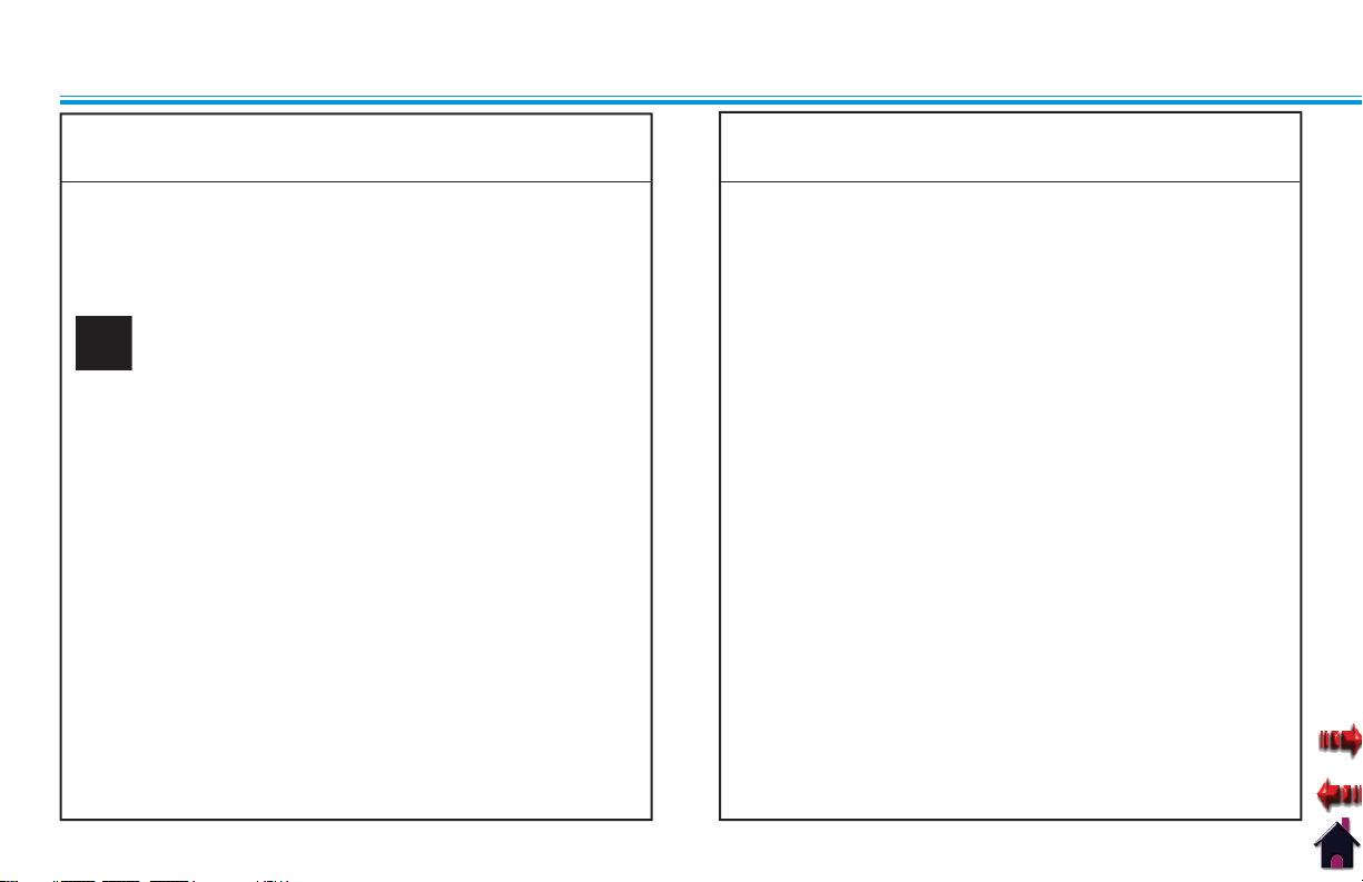
FRONT VIEW
1
15
14
13
12
2
Intelect® Shortwave 100
3
2
4
6
5
7
8
9
10
User Interface (see 1. page 30)
Arm Extender Lock Knobs2.
Electrode Lock Knobs3.
Front Handwheel4.
Arm Extenders5.
Capacitive Electrodes 120 mm6.
Electrode arm7.
Rear Handwheel8.
Electrode connection cable9.
Locking castor10.
Non locking castors11.
IEC Connector for Power Cord12.
Storage Bin13.
Grab Bar14.
Swivel Console15.
11
28
Page 33

NOMENCLATURE
Supplied by EME Services Ltd
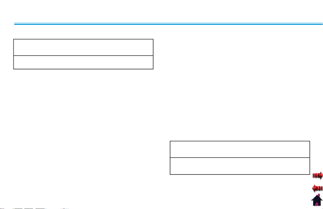
REAR VIEW
1
4
3
Intelect® Shortwave 100
Expansion Port (for Service Use only)1.
Output Sockets2.
Patient Interrupt Cord3.
Cable Clips4.
2
29
Page 34

NOMENCLATURE
Supplied by EME Services Ltd
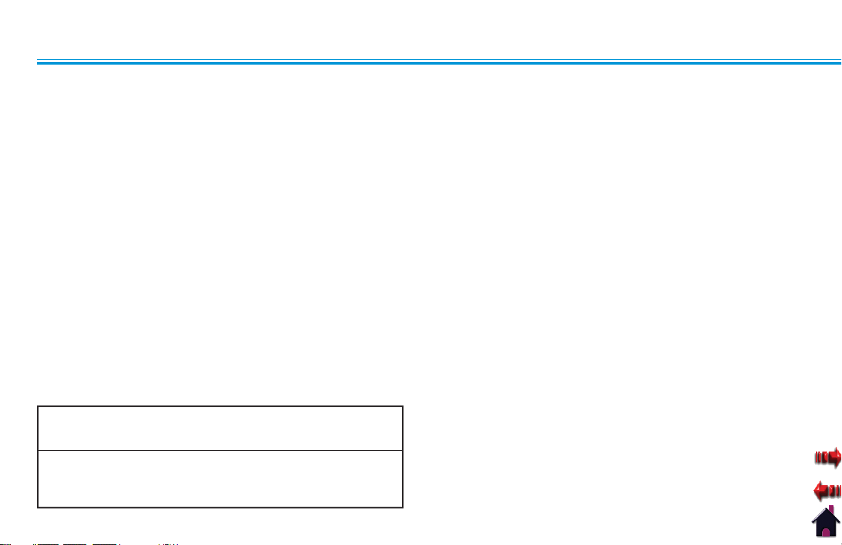
USER INTERFACE
1
9
8
Intelect® Shortwave 100
2
Power On/Off Button1.
Liquid Crystal Display (LCD) and Touch Screen2.
Clinical Resources Button3.
START Button4.
3
PAUSE Button5.
Multimedia Card (MMC) Port6.
Patient Data Card Port7.
STOP Button8.
Power LED9.
4
5
6
7
30
Page 35

NOMENCLATURE
Supplied by EME Services Ltd
SOFTWARE SYMBOLS
Intelect® Shortwave 100
Display the Edit Treatment Screen
Up Arrow (Increase)
Down Arrow (Decrease)
Touch and Slide Left to Increase
Touch and Slide Right to Decrease
Back (Return to Previous Screen)
Display the Home Screen
Move the cursor to the left one space
Move the cursor to the right one space
Accept/Select (Parameters)
Cancel and Return to Previous Screen
Display Information
Change Text to Upper Case
Change Text to Lower Case
Shortwave Diathermy is being emitted
Pause
Unit is Tuning
31
Page 36

NOMENCLATURE
Supplied by EME Services Ltd
ACCESSORIES
Keep all electrodes, accessories, and their cords separated during
treatment by using the cable clips located on the side of the arm
extenders. Electrodes or their cords in contact with each other during
treatment could result in improper stimulation, skin burns, or damage
to the cord or electrode.
Capacitive Electrodes
Capacitive Electrode 1.
165 mm (6.5 in)
Capacitive Electrode 2.
120 mm (4.7 in)
Electrode connection 3.
cable
Intelect® Shortwave 100
Flexible Rubber Electrodes
Flexible Rubber Electrode 250 x 145 mm (9.8 x 5.7 in)1.
Flexible Rubber Electrode 180 x 120 mm (7.1 x 4.7 in)2.
Felt layer with linen bag for 1 and 23.
Perforated rubber band with 2 buttons4.
32
Page 37

NOMENCLATURE
Supplied by EME Services Ltd
ACCESSORIES CONTINUED
Intelect® Shortwave 100
Monode (Drum) Electrode
14 cm (5.5 in) round Monode (Drum) Electrode with cable
Diplode Electrodes
18 x 39 cm (7 x 15.4 in) curved rectangular Diplode Electrode with
cable
Indicator Discharge Tube
To verify that shortwave diathermy energy is actually being
transmitted, this small, fluorescent tube illuminates when it’s held
between the capacitive or flexible rubber electrodes, or near the
monode and diplode (assuming a therapy session is in progress).
NOTE: The indicator discharge tube will not illuminate if the
output power is at a low setting.
33
Page 38

SPECIFICATIONS
Supplied by EME Services Ltd
Intelect® Shortwave 100
UNIT SPECIFICATIONS
HEIGHT
DEPTH
Certifi ed to CAN/CSA STD C22.2 No. 601.1
WIDTH
1604
1602
0413
Operating Data and Ratings
Width* . . . . . . . . . . . . . . . . . . . . . . . . . . . . . . . . . . . . . . . . . . . . . 420 mm (16.5")
Depth*. . . . . . . . . . . . . . . . . . . . . . . . . . . . . . . . . . . . . . . . . . . . 410 mm (16.14")
Height* . . . . . . . . . . . . . . . . . . . . . . . . . . . . . . . . . . . . . . . . . . . . 1143 mm (45")
Standard Weight (with diplode electrode) . . . . . . . . . 27.22 kg (60 lbs)
Ambient temperature. . . . . . . . . . . . . . +10 °C to 40 °C (50 °F to 104 °F)
Relative Humidity . . . . . . . . . . . . . . . . . . . . . . . . . . . . . . . . . . . . . 30% to 75%
Air Pressure . . . . . . . . . . . . . . . . . . . . . . . . . . . . . . . . . . . 700 hPa to 1060 hPa
Power Consumption . . . . . . . . . . . . . . . . . . . . . . . . . . . . . . . . . . . . . . . 500 VA
Input. . . . . . . . . . . . . . . . . . . . . . . . . . 120-240 V ~, 50/60 Hz (Model 1602)
. . . . . . . . . . . . . . . . . . . . . . . . . . . . . . . . . . . . . . . 120 V ~, 60 Hz (Model 1604)
Output Frequency . . . . . . . . . . . . . . . . . . . . . . . . . . . . . . 27.12 MHz ± 0.6%
Mode . . . . . . . . . . . . . . . . . . . . . . . . . . . . . . . . . . . . . . . .Pulsed or Continuous
Output Power. . . . . . . . . . . 0 - 100 W in continuous mode at 50 ohms
. . . . . . . . . . . . . . . . . . . . . . . . . . . . .0 - 200 W in pulsed modes at 50 ohms
Power Increment Settings. . . . . . . . . . . . . . . . . . . . . . . . . . . . . . . . . . . . . .5 W
Power Indication . . . . . . . . . . . . . . . . . . . .maximum and average power
Pulse Width . . . . . . . . . . . . . . . . . . . 20 - 400 µsec in 20 µsec increments
Pulse Frequencies. . . . . . . . . . . . . . . . . 10 - 800 Hz in 10 Hz increments
Treatment Duration . . . . . . . . .1 - 60 minutes in 1 minute increments
Electrical Class . . . . . . . . . . . . . . . . . . . . . . . . . . . . . . . . . . . . . . . . . . . . .CLASS I
Electrical Type (Degree of Protection). . . . . . . . . . . . . . . . . . TYPE BF
Regulatory Risk Class . . . . . . . . . . . . . .IIb according to MDD 93/42/EEC
* without electrodes, electrode arm, and electrode cables
34
Page 39

SPECIFICATIONS
Supplied by EME Services Ltd
UNIT SPECIFICATIONS CONTINUED
Software
The software is developed and provided by Chattanooga Group.
©2009 Encore Medical, L.P. and its affiliates, Austin, Texas, USA.
To view the version of the software, press the Unit Settings button
on the Clinical Resources screen. The version number of the
software appears at the top of the screen.
Transport and Storage Conditions
Ambient temperature. . . . . . . . . . . . . . -40 °C to 70 °C (-40 °F to 158 °F)
Relative Humidity . . . . . . . . . . . . . . . . . . . . . . . . . . . . . . . . . . . . . 30% to 75%
Air Pressure . . . . . . . . . . . . . . . . . . . . . . . . . . . . . . . . . . . . .50 kPa to 1060 kPa
Safety
The Intelect Shortwave 100 has been designed to meet the
requirements of IEC/EN 60601-1, 60601-2-3, 60601-1-2, and
60601-1-4.
In order to prevent excessive warming of tissue, the maximum and
average output power must not be exceeded.
Intelect® Shortwave 100
35
Page 40

SPECIFICATIONS
Supplied by EME Services Ltd
Intelect® Shortwave 100
APPLICATOR SPECIFICATIONS
Pay special attention to the list of contraindications. Refer to "Safety Instructions" on pages 5-11, "Contraindications" on pages 20-23,
"Additional Precautions" on pages 24-25, and "Personal Safety" on pages 12-13.
36
Page 41

SPECIFICATIONS
Supplied by EME Services Ltd
Intelect® Shortwave 100
DESCRIPTION OF DEVICE MARKINGS
The markings on the Intelect Shortwave 100 system are your assurance of its conformity to the highest applicable standards of medical equipment safety
and electromagnetic compatibility. One or more of the following markings may appear on the device:
Meets Directive 93 /42 /EEC, Complies with
21CFR 1040.10 &1040.11 IEC/UL/EN: IEC/EN 60601-1,
60601-2-3, 60601-1-2, and 60601-1-4
Electromedical equipment, Canadian Electrical Code.
Part II: Safety standards for Electrical Equipment Risk Class I.
Listed by Intertek Group, PLC with respect to electric
shock, fire and mechanical hazards only in accordance
with UL 60601-1, and CAN/CSA C22.2 No. 601.1-M90
w/Amd 2.
Refer to Instruction Manual/Booklet
Type BF Equipment
Council Directive 2002/96/EC concerning Waste Electrical
and Electronic Equipment (WEEE). Indicates a requirement
not to dispose of WEEE as municipal waste. Contact your local
distributor for information regarding disposal of the unit and
accessories.
0413
9700675
Adjustments or replacement of components may result in
the equipment failing to meet the requirements for
interference suppression.
Non-ionizing Electromagnetic Radiation. Text with a
“Non-ionizing Electromagnetic Radiation" indicator
informs the user of possible hazards resulting from
elevated, potentially dangerous, levels of non-ionizing
radiation.
37
Page 42

OPERATION
Supplied by EME Services Ltd
Intelect® Shortwave 100
DESCRIPTION OF FUNCTIONS
Introduction
The Intelect Shortwave 100 unit can produce dielectric warming by means of electric or electromagnetic fields of varying intensity in
essentially any region of the body and can therefore be used for a wide variety of applications.
Treatments can be carried out using either the capacitive field or the inductive field method. In the capacitive field method, the body part
to be treated is within the electric field between two capacitive electrodes. The “radiation” produces a warming of the body part located
within the induction field. Fat layers are warmed considerably more than muscle tissue. When applying the inductive field method, the
body part is within a magnetic field, which especially warms tissue containing liquid located near the surface, such as muscles.
Applications
The shortwave diathermy unit is suitable for nearly all heat therapy processes for use in clinics and private practices. Classical therapy
applications can be conducted with the inductive field and capacitive field methods in continuous or pulsed mode.
The application of high-frequency energy in heat therapy has the advantage of greater depth penetration as opposed to simpler methods,
such as packs, baths, infrared light, and heat cushions.
The endogenous heat that is formed triggers a series of physiological processes, producing a spasmolytic effect on muscles, tendons, and
other structures containing connective tissue, increasing the cell metabolism and the enzyme reaction speed and stimulating perfusion in
the treated zone.
The capability of applying the high-frequency energy in short, intense pulses (pulsed mode) can further increase the depth effectiveness,
especially the stimulation of perfusion, while the heat generation is hardly felt in the skin, which is more sensitive to heat.
The applications for the high-frequency therapy are diverse. This therapy is especially effective in treating rheumatic disorders of the joints
and muscles, inflammatory disorders of the respiratory organs, the kidneys and bile ducts, and all disorders due to insufficient perfusion.
The pulsed mode is advantageous in the treatment of acute conditions.
Intelect Shortwave 100 units are therefore used for a wide range of applications in hospitals and in private practices by doctors and
physiotherapists.
38
Page 43

OPERATION
Supplied by EME Services Ltd
DESCRIPTION OF FUNCTIONS CONTINUED
Intelect® Shortwave 100
Shortwave Diathermy in the Capacitive (Dielectric)
Field
12
3
Heat distribution with a small Electrode-Skin Distance (ESD)1.
Heat distribution with a large Electrode-Skin Distance (ESD)2.
Heat distribution with an unequal Electrode-Skin Distance (ESD)3.
With the capacitive field method, the body part being treated is
located in the high-frequency electric field between two insulated
electrodes. The body and the electrodes together form a capacitor.
This causes heat to be generated in the entire treatment field
located between the electrodes.
With the capacitive method, fat tissue is warmed more effectively
than muscle tissue.
Capacitive electrodes and flexible rubber electrodes are used for
the capacitive method.
An adjusting device on the capacitive electrodes or layers of felt
with the flexible rubber electrodes can be used to achieve different
Electrode-Skin Distances (ESD).
The Electrode-Skin Distance (ESD) must be small for surface warming
and large for depth warming. A larger Electrode-Skin Distance (ESD) is
necessary for patients with a thick layer of subcutaneous fat in order to
achieve the necessary warming of deep-lying tissue.
39
Page 44

OPERATION
Supplied by EME Services Ltd
Intelect® Shortwave 100
DESCRIPTION OF FUNCTIONS CONTINUED
Shortwave Diathermy in the Inductive Field
The inductive field method produces high-frequency electric currents within the body tissue by means of induction. The high-frequency
circuit of closed currents occurring in the tissue as a result of induction are referred to as eddy currents. The density of these eddy currents,
which is important for the warming effect, is proportional to the electrical conductivity of the tissue. At the same field intensity, therefore,
tissue with better conductivity, such as muscles and inner organs, are warmed more than fat tissue. The danger of excessive heating of the
outer layers of tissue is therefore significantly reduced, while effective warming down into the muscles is primary.
Two different inductive electrodes are available:
Monode (Drum) Electrode for treatment of mid-sized areas.
•
Diplode for treatment of large areas and for treatment of suitable body parts that can be warmed from three sides at the same time.•
With the inductive field electrodes, the perception of warming is delayed. It is recommended to remain below the desired power output at
the beginning of the treatment and then to increase the power in increments.
Inductive field electrodes that are operated without a patient could be
destroyed due to overheating.
40
Page 45

OPERATION
Supplied by EME Services Ltd
INSTALLING THE APPLICATORS
Intelect® Shortwave 100
Installing the Capacitive Electrodes
Remove the cable from the 1.
electrode.
Loosen the Electrode Lock 2.
Knob by turning it counter
clockwise.
Push the electrode rod 3.
through the hole in the
extension arm until the
electrode rod is barely seen
on the other side of the
hole.
Tighten the Electrode 4.
Lock Knob by turning it
clockwise.
41
Page 46

OPERATION
Supplied by EME Services Ltd
INSTALLING THE APPLICATORS CONTINUED
Intelect® Shortwave 100
Re-attach the cable to the 5.
electrode.
Fit the cord of the 6.
electrode into the cable
clip on the outside of the
arm.
Plug the connector of the 7.
electrode cable into the
output socket on the rear
panel.
Repeat steps 1-7 for the 8.
additional electrode.
Do not cross cables.•
To remove the cable from the applicator, make certain the power •
is off. While the electrode applicator is being supported by the
electrode arm, hold the electrode while removing the cable to
prevent the electrode from dropping to the floor.
Tighten arms so that they do not move during therapy.
•
Observe the patient and the position of the arms at all times during •
therapy.
Inform the patient that the arms are not supposed to move during
•
therapy.
Before using the unit, verify the patient is not in contact with the
•
unit, the electrode connection cable, the electrodes, or other devices
or metal objects.
42
Page 47

OPERATION
Supplied by EME Services Ltd
INSTALLING THE APPLICATORS CONTINUED
Intelect® Shortwave 100
Installing the Monode (Drum) and Diplode
Electrodes
The Monode and Diplode are installed identically. However, only the
monode is illustrated in this section.
Remove the black, plastic 1.
retaining T nut from the
sleeve by turning it counter
clockwise.
Slide the sleeve off the 2.
metal mounting post of
the monode.
Remove the Electrode Lock 3.
Knob by turning it counter
clockwise.
Push the sleeve completely 4.
through the hole in the
extension arm.
43
Page 48

OPERATION
Supplied by EME Services Ltd
INSTALLING THE APPLICATORS CONTINUED
Reattach and tighten the 5.
Electrode Lock Knob by
turning it clockwise until it
is snug.
Push the metal mounting 6.
post of the monode
completely through the
sleeve.
Intelect® Shortwave 100
Re-attach and tighten the 7.
black, plastic retaining T
nut onto the sleeve by
turning it clockwise.
Fit the cord of the monode 8.
into the cable clip on the
outside of the arm.
44
Page 49

OPERATION
Supplied by EME Services Ltd
INSTALLING THE APPLICATORS CONTINUED
Intelect® Shortwave 100
Plug the connectors of the 9.
monode cable into the
output sockets on the rear
panel.
To remove the cable from the applicator, make certain the power •
is off. While the electrode applicator is being supported by the
electrode arm, hold the electrode while removing the cable to
prevent the electrode from dropping to the floor.
Tighten arms so that they do not move during therapy.
•
Observe the patient and the position of the arms at all times during •
therapy.
Inform the patient that the arms are not supposed to move during
•
therapy.
Before using the unit, verify the patient is not in contact with the unit,
•
the electrode connection cable, the electrodes, or other devices or
metal objects.
Installing the Flexible Rubber Electrodes
Installation of the Flexible Rubber electrodes is only necessary
immediately before therapy. For more information, refer to "Using
the Flexible Rubber Electrodes" on page 76.
45
Page 50

OPERATION
Supplied by EME Services Ltd
PREPARING THE UNIT FOR THERAPY
The unit has been completely assembled in the factory and is
ready for use except for connection of the electrodes and the
power cord.
Proceed as follows in order to prepare the unit for operation:
•
Make sure that the voltage rating on the serial decal
conforms to the system voltage of the building.
Insert the required electrodes into the recesses at the end •
of the electrode arms and fasten the electrodes with the
locking screws. See pages 41-42 for more information on
installing the electrodes.
Plug the electrode connection cable into the socket on the •
back of the unit. Attach the connecting cable in the cable
holders on the electrode arms.
Check the condition of the housing and the insulation of •
the electrodes, electrode connection cable and the power
supply cable. Also make sure that the cables have been
routed correctly.
Insert the power cord plug into an earthed socket outlet.•
Intelect® Shortwave 100
The unit and the electrodes must be positioned so that there is no
danger of personal injury. Therefore, you must read and observe the
safety instructions and the list of contraindications before putting the
unit into operation.
Make certain that the unit is electrically earthed by connecting
only to an earthed electrical service receptacle, conforming to the
applicable national and local electrical codes.
46
Page 51

OPERATION
Supplied by EME Services Ltd
PREPARING THE PATIENT FOR THERAPY
Before applying shortwave diathermy to the patient, you must first
prepare the patient’s skin. By properly preparing the patient’s skin
for shortwave diathermy, you will allow more energy to reach the
targeted areas and reduce the risk of skin irritation.
To prepare the patient’s skin for shortwave diathermy, do the
following:
Thoroughly wash the skin on which you intend to administer 1.
shortwave diathermy therapy with mild soap and water or
alcohol wipe.
Dry the skin thoroughly.2.
Before using the unit, verify the patient is not in contact with the unit,
the electrode connection cable, the electrodes, or other devices or
metal objects.
Intelect® Shortwave 100
47
Page 52

OPERATION
Supplied by EME Services Ltd
BASIC OPERATION
Connect the male end of 1.
the power supply cord to
an appropriate electrical
outlet.
Connect the female end of 2.
the power supply cord into
the IEC connector on the
side of the unit.
Intelect® Shortwave 100
Press the Power On/Off 3.
button or touch the LCD.
The following occurs when
the Power On/Off button
is pressed or the LCD is
touched:
three quick beeps
•
sound
the blue LED illuminates•
the Home Screen •
displays.
The Operator Interface consists of buttons with a touch screen
liquid crystal display (LCD). The operator is able to view parameter
options on the display and make selections by pressing the buttons
directly on the LCD. The LCD provides continuous information
during the treatments concerning dosage and elapsed time.
Parameters are adjusted using the and buttons. The output
can be stopped by the user by pressing the PAUSE or STOP buttons
located on the Operator Interface. The patient can stop the therapy
treatment at any time by pulling the cord of the patient interrupt
cord.
48
Page 53

OPERATION
Supplied by EME Services Ltd
STARTING THERAPY
Intelect® Shortwave 100
The Intelect Shortwave 100 offers the following methods from
which you can begin a treatment session:
• page 51)
Thermal Dosimetry (
Quick Link Indications (• page 52)
Clinical Protocols (• page 56)
User Protocols (• page 58)
Home screen (• page 52)
Patient Card (• page 65)
Home Screen
The Home screen serves as the main treatment screen. After the
treatment parameters have been selected, you may increase or
decrease the output power (in watts) during therapy on the Home
screen by using the and buttons.
Edit Treatment Screen
On the Home Screen, press 1.
the button. The Edit
Treatment screen displays.
Increase the parameters on 2.
the Edit Treatment screen
by pressing the button.
Decrease the parameters 3.
by pressing the button.
You may also increase and 4.
decrease parameters by
pressing and sliding the
button either left or right.
49
Page 54

OPERATION
Supplied by EME Services Ltd
STARTING THERAPY CONTINUED
Press the Mode button 5.
to select either Pulsed or
Continuous.
NOTE: Pulse Rate and
Press the 6.
return to the previous
screen.
Press the 7. button to
return to the Home screen.
Pulse Width
parameters are
not available
when the
Continuous
mode is selected
and the Diplode
or Monode
electrodes are
selected.
button to
Intelect® Shortwave 100
Electrode Screen
On the Edit Treatment 1.
screen, press the Electrode
button at the top of the
screen. The Select Electrode
screen displays.
Press the electrode to 2.
highlight it, or press the
and buttons to
scroll through a list of the
available electrodes.
Press the 3. button to
accept the highlighted
selection and return to the
Edit Treatment screen.
Press the 4. button to
return to the previous
screen.
50
Page 55

OPERATION
Supplied by EME Services Ltd
STARTING THERAPY CONTINUED
Intelect® Shortwave 100
Thermal Dosimetry
Press the 5. button to
return to the Home screen.
On the Home screen, press 1.
the Thermal Dosimetry
button. The Select Thermal
Dosimetry screen displays.
Press the button next to 2.
the appropriate dosage
and applicable indication.
You are returned to
the Home screen with
the parameters of the
indication displayed to
begin treatment.
51
Page 56

OPERATION
Supplied by EME Services Ltd
BASIC OPERATION CONTINUED
Quick Link Indications
By pressing the Quick Link Indications button on the Home screen,
you can access specific pre-programmed indications, for general
reference only, which aid in selecting the proper output and
electrode placement for particular indicated patient syndrome
diagnoses.
On the Home screen, press 1.
the Quick Link Indications
button. The Quick Link
Indications screen displays.
Click one of the buttons on 2.
the Quick Link Indications
screen (depending on the
needs and symptoms of
the patient). The Home
screen displays with
the pre-set parameters
for the indication you
selected displays to begin
Intelect® Shortwave 100
treatment. For example,
you may have pressed the
Acute Pain button which
would cause the Acute
Pain screen to display.
Starting Therapy from the Home Screen
On the Home screen, press 1.
the and buttons
to set the appropriate
output power (in watts) for
therapy.
NOTE: You can only set
the treatment
time on the Edit
Treatment screen.
52
Page 57

OPERATION
Supplied by EME Services Ltd
BASIC OPERATION CONTINUED
Press the START button on 2.
the User Interface to begin
treatment. When the START
button is pressed:
a beep sounds•
the unit begins auto •
tuning (clicking can be
heard)
the unit begins emitting •
shortwave diathermy
energy
the timer counts down•
the • icon
displays.
Intelect® Shortwave 100
Indicator Discharge Tube
To verify that shortwave energy is actually being transmitted, this
small, fluorescent tube illuminates when it’s held between the rigid
condenser electrodes and the flexible rubber electrodes (assuming
a therapy session is in progress).
NOTE: The indicator discharge tube will not illuminate if the
output power is at a low setting.
53
Page 58

OPERATION
Supplied by EME Services Ltd
STOPPING, PAUSING, AND COMPLETING THERAPY
Stopping Therapy Using the STOP Button
To stop shortwave diathermy, press the STOP button on the User
Interface. When the STOP button is pressed:
•
the applicator stops emitting shortwave diathermy energy.
the message "• Treatment has been stopped by user. Do you
want to save treatment to a Patient Card?"
the unit sounds long tones until you press a button on the •
message window.
If you choose to save the 1.
current parameters to a
patient card, press the
Yes button and follow the
instructions on page 68,
beginning with step 2.
If you do not want to save 2.
the current parameters,
press the No button. You
are returned to the Home
screen.
Intelect® Shortwave 100
Stopping Therapy Using the Patient Interrupt Cord
If the therapy is stopped by pulling the cord of the Patient Interrupt
Cord:
•
the applicator stops emitting shortwave diathermy energy
The • (pause) symbol displays and blinks
the message "• Treatment has been stopped by the patient.
Press any button to continue."
Press any button on the 1.
unit to acknowledge the
message. The treatment
can be resumed by
pressing the Pause or Start
buttons.
54
Page 59

OPERATION
Supplied by EME Services Ltd
STOPPING, PAUSING, AND COMPLETING THERAPY
Pausing Therapy
The therapy can be interrupted at any time by pressing the PAUSE
button on the User Interface. When the PAUSE button is pressed,
the following occurs:
•
the applicator stops emitting shortwave diathermy energy
The • (pause) symbol displays and blinks
To resume therapy, press the PAUSE button on the User Interface.
Completing the Therapy Session
When the treatment time expires:
the applicator stops emitting shortwave diathermy energy•
the message "• Treatment has completed. Do you want to save
treatment to a Patient Card?"
the unit sounds long tones until you press a button on the •
message window.
Intelect® Shortwave 100
If you choose to save the 1.
current parameters to a
patient card, press the
Yes button and follow the
instructions on page 68,
beginning with step 2.
If you do not want to save 2.
the current parameters,
press the No button. You
are returned to the Home
screen.
55
Page 60

OPERATION
Supplied by EME Services Ltd
Intelect® Shortwave 100
USING CLINICAL PROTOCOLS
The indications contained in this section are to be used only as guidelines. Each patient should be individually assessed to determine the
appropriateness of the parameter setting prior to use.
Insert the MMC labeled 1.
"SWD Clinical Resource
Library" into the MMC port.
On the Home screen, 2.
press the Clinical Protocols
button. The Clinical
Protocols screen displays.
Press the specific body area 3.
on the front or back image
to select the desired body
area to treat. The screen
unique to the area of the
body you pressed displays.
If applicable, press the 4.
and buttons to
scroll through the pages of
protocols.
Press the protocol to 5.
highlight it, or press the
and buttons to scroll
through the list.
Press the 6. button to
accept the highlighted
selection. The suggested
parameter and electrode
screen displays.
To select this protocol and 7.
begin treatment, press the
button. The Home
screen displays and you
can begin treatment.
If you want to change 8.
the electrode placement
(e.g. the recommended
electrode does not match
the electrode you are
56
Page 61

OPERATION
Supplied by EME Services Ltd
USING CLINICAL PROTOCOLS CONTINUED
using), press the Electrode
Placement button. The next
Clinical Protocols screen
displays.
Intelect® Shortwave 100
Press the 10. button. The
Home screen displays with
the new parameters.
Press one of the electrode 9.
placement images
to change electrode
placement. The suggested
parameter and electrode
screen displays. Notice
that the electrode details
changed to match the new
electrode placement image
selection.
57
Press the 11.
buttons to set the
appropriate output power
for treatment.
Press the EDIT button to 12.
change the parameters.
Press the START button to 13.
begin treatment.
and
Page 62

OPERATION
Supplied by EME Services Ltd
Intelect® Shortwave 100
RETRIEVING, DELETING, AND SAVING USER PROTOCOLS
The Intelect Shortwave 100 unit allows you to tailor a protocol according to the requirements of a patient. The treatment parameters
selected at the home screen can be saved as a new user protocol or saved to replace a previously saved user protocol. You may create up
to 200 user protocols.
Retrieving User Protocols
On the Home screen, press 1.
the User Protocols button.
The User Protocols screen
displays.
Press the Retrieve Protocol 2.
button. The Retrieve
Protocol screen displays.
Press or scroll to the 3.
desired user protocol
to view the treatment
parameters.
Press 4. to select the
highlighted protocol. You
are returned to the Home
screen to begin treatment.
Deleting User Protocols
To delete the highlighted 1.
user protocol, press the
Delete button on the
Retrieve Protocol screen. A
message displays to verify
the deletion.
Press the Yes button to 2.
delete the user protocol.
You are returned to the
Retrieve Protocol screen.
NOTE: If you press Yes,
the user protocol
name and
parameters will
be permanently
removed from the
unit.
58
Page 63

OPERATION
Supplied by EME Services Ltd
RETRIEVING, DELETING, AND SAVING USER PROTOCOLS CONTINUED
Intelect® Shortwave 100
Saving New User Protocols
Press the No button to 3.
keep the user protocol
and return to the Retrieve
Protocol screen.
Set up treatment 1.
parameters by completing
the steps listed in "Starting
Therapy" on pages 49-51,
but do not press the START
button.
On the Home screen, press 2.
the User Protocols button.
The User Protocols screen
displays.
Press Save Protocol. The 3.
Save Protocol screen
displays.
To create a name for 4.
the new protocol, press
the Save Protocol as a
New Name button. The
Keyboard screen displays.
Type the name of the new 5.
protocol. The name of
the new protocol can be
up to 25 alpha-numeric
characters.
59
Page 64

OPERATION
Supplied by EME Services Ltd
RETRIEVING, DELETING, AND SAVING USER PROTOCOLS CONTINUED
Intelect® Shortwave 100
Editing Existing User Protocols
Press the 6. button
to save the name of the
protocol. A message
displays briefly to confirm
the protocol was saved.
The Home screen displays
the parameters of the user
protocol you just saved.
To edit the treatment 1.
parameters of a previously
saved user protocol, press
to highlight, or scroll
through the list of user
protocols and highlight the
appropriate user protocol.
Press the 2.
save the new treatment
parameters. A message
displays to confirm the
overwriting of the old
parameters. If you press
Yes, a message displays
briefly to confirm the
protocol was saved and
the Home screen displays
the parameters of the
user protocol you just
saved. If you press No, you
are returned to the Save
Protocol screen.
button to
60
Page 65

OPERATION
Supplied by EME Services Ltd
USING CLINICAL RESOURCES EDUCATIONAL LIBRARY
Intelect® Shortwave 100
The Educational Library can be accessed by pressing the button with the
screen display. The Clinical Resources screen allows you access to the Educational Library, Patient Card management, and Utilities screens.
Anatomical Graphics Library
The Anatomical Graphics Library features graphical images of the
human anatomy and pathological conditions for which shortwave
diathermy is used. To access the Anatomical Graphics Library, make
sure the MMC labeled "SWD Clinical Resource Library" is in the MMC
port and do the following:
On the Clinical Resources 1.
screen, press the
Anatomical Graphics
Library button. The
Anatomical Graphical
Library screen displays.
icon (Clinical Resources button) located below the touch
Press the button of the 2.
body area on which you
intend to administer
therapy. The screen that
corresponds to the body
area you selected displays.
For example, you may
have pressed the back
of the neck which would
cause the Neck: Page 1 of 2
screen to display.
If available, press the 3.
icon to display
additional pathological
images.
61
Page 66

OPERATION
Supplied by EME Services Ltd
USING CLINICAL RESOURCES EDUCATIONAL LIBRARY CONTINUED
Intelect® Shortwave 100
Press a button on the 4.
left side of the screen
(Anatomical Images) to
display a list of either
muscles or bones that
make up the area.
Press the 5.
return to the previous
screen.
Press a button on the 6.
right side of the screen
(Pathological Images)
to display an illustration
of a common disorder
associated with the body
area.
Press the 7. button to
return to the previous
screen.
button to
Electrode Placement Library
The Electrode Placement Library serves as a guideline for the
placement of electrodes for shortwave diathermy.
On the Clinical Resources 1.
screen, press the Electrode
Placement Library button.
The Select Treatment Area
screen displays.
Press the body area on 2.
which you intend to
administer therapy. The
screen that corresponds to
the body area you selected
displays. For example, if you
press the back of the neck,
the Electrode Placement:
Neck displays.
62
Page 67

OPERATION
Supplied by EME Services Ltd
USING CLINICAL RESOURCES EDUCATIONAL LIBRARY CONTINUED
Press one of the electrode 3.
placement thumbnails to
view the entire picture of
the electrode placement.
The Electrode Placement
screen displays.
Intelect® Shortwave 100
Press the 4.
return to the previous
screen.
Press the 5. button to
return to the Home screen.
button to
63
Page 68

OPERATION
Supplied by EME Services Ltd
USING CLINICAL RESOURCES EDUCATIONAL LIBRARY CONTINUED
Intelect® Shortwave 100
Diathermy Rationale
Pressing the Diathermy Rationale button displays an overview of
shortwave diathermy, a list of available treatment options, and a
synopsis of the available parameters.
On the Clinical Resources 1.
screen, press the Diathermy
Rationale button. The
Shortwave Diathermy
Rationale screen displays.
Press the 2.
buttons to scroll through
the information.
Press the 3. button to
return to the previous
screen.
Press the 4. button to
return to the Home screen.
and
Contraindications
Pressing the Contraindications button displays a list of conditions
for which shortwave diathermy is contraindicated.
On the Clinical Resources 1.
screen, press the
Contraindications button.
The Contraindications
screen displays.
Press the 2.
buttons to scroll through
the information.
Press the 3. button to
return to the previous
screen.
Press the 4. button to
return to the Home screen.
64
and
Page 69

OPERATION
Supplied by EME Services Ltd
USING CLINICAL RESOURCES PATIENT CARD
The Patient Card buttons serve to manage the information stored on a patient's data card.
NOTE: This button is only active when a patient card is inserted into the patient card port on the device.
Intelect® Shortwave 100
Viewing and Retrieving Treatments from the Patient
Card
Press the Patient Card button to access the patient treatment data
stored on the patient card.
On the Clinical Resources 1.
screen, press the Patient
Card button. The Patient
Card screen displays.
Press the 2. and
buttons to scroll through
the treatment sessions. The
treatment parameters for
the highlighted treatment
display at the top of the
screen.
65
Press the 3.
buttons if the number of
treatment sessions extend
beyond one page.
Press the 4. button
to select the treatment
session. The treatment
parameter screen displays.
Review the parameters of 5.
the treatment session.
Press the Run this 6.
Treatment button to begin
treatment.
and
Page 70

OPERATION
Supplied by EME Services Ltd
USING CLINICAL RESOURCES PATIENT CARD CONTINUED
Edit Pain Profile
The Edit Pain Profile button allows access to the screen for pain
information to be saved to the patient card while a therapy session
is in progress. This information includes:
Pain Scale before treatment•
Pain Scale after treatment•
Pain Type before treatment•
Pain Type after treatment•
Pain Map before treatment•
Pain Map after treatment•
Treatment Area•
Intelect® Shortwave 100
In the Pain Before 2.
Treatment section, press to
select either a Numeric or
Visual pain scale.
Press the 3. button to
decrease the amount of
pain on the scale.
Press the 4. button to
increase the amount of
pain on the scale.
On the Clinical Resources 1.
screen, press the Edit Pain
Profile button. The Edit Pain
Profile screen displays.
Press the Pain Type button. 5.
The Select Pain Type Before
Treatment screen displays.
Press the pain type or use 6.
the , , and
buttons to select the pain
type. You are returned to
the Edit Pain Profile screen
with the new pain type
selected.
66
Page 71

OPERATION
Supplied by EME Services Ltd
USING CLINICAL RESOURCES PATIENT CARD CONTINUED
Intelect® Shortwave 100
Press the Edit Pain Map 7.
button. The Pain Map
Before Treatment screen
displays.
Press the body area on 8.
which you intend to
administer therapy. A
purple shading displays in
the areas you press.
Press the Clear button 9.
to remove all the areas
previously selected in the
previous step.
In the Pain After Treatment 10.
section, repeat steps 2-9.
Press the Treatment 11.
Area screen. The Select
Treatment Area screen
displays.
Press the specific body 12.
area on the front or back
image to select the desired
body area to treat. You are
returned to the Edit Pain
Profile screen.
Press the Save to Patient 13.
Card to save the pain
information to the patient's
card.
Press the 14. button
to return to the Clinical
Resources screen.
Press the 15. button to
return to the Home screen.
67
Page 72

OPERATION
Supplied by EME Services Ltd
USING CLINICAL RESOURCES PATIENT CARD CONTINUED
Saving Treatments to the Patient Card
If the treatment time expires during a treatment, or if you stop a
treatment using the STOP button, the unit gives you the option of
saving the treatment to a patient card.
Press Yes when prompted 1.
to save to the patient card.
Follow steps 2-13 on 2. pages
66-67.
Intelect® Shortwave 100
When you press the Sa
to Patient Card button, the
message "Treatment has
been saved for (patient
name)" briefly displays.
ve 3.
68
Page 73

OPERATION
Supplied by EME Services Ltd
USING CLINICAL RESOURCES PATIENT CARD CONTINUED
Intelect® Shortwave 100
Erasing Patient Card
Use this button to remove all information on the Patient Card.
To delete all information on 1.
the Patient Card, insert the
patient card to be erased
into the Patient Data Card
Port.
Press the Erase Patient Card 2.
button. A message displays
to verify the deletion.
Press the No button if you 3.
do not want to erase all the
information on the Patient
Card. You are returned
to the Clinical Resources
screen.
Press the Yes button to 4.
erase all the information on
the Patient Card.
NOTE: By pressing the
Yes button, you
will permanently
remove all data on
the Patient Card.
You are returned to the
Clinical Resources Screen.
69
Page 74

OPERATION
Supplied by EME Services Ltd
Intelect® Shortwave 100
USING CLINICAL RESOURCES UNIT SETTINGS
To access the Unit Settings screen, press the Unit Settings button on the Clinical Resources screen. The version number of the software
appears at the top of the screen.
Adding and Changing the Clinic Name
On the Clinical Resources 1.
screen, press the Unit
Settings button. The Unit
Setup screen displays.
On the Unit Setup screen, 2.
press the Clinic Name
button. The Keyboard
screen displays.
Type the name of the new 3.
protocol. The name of the
protocol can be up to 25
alpha-numeric characters.
Press the 4. button
to save the name of the
protocol and return to the
Unit Settings screen.
Press the 5.
delete the new information
you may have entered and
return to the Unit Settings
screen.
button to
Increasing and Decreasing the Unit Volume
On the Unit Settings screen, press the Volume button repeatedly
until the appropriate volume level displays. Each time you press the
Volume button, a tone sounds at the volume level displayed. The
volume will remain at the same level, even after powering the unit
off.
70
Page 75

OPERATION
Supplied by EME Services Ltd
USING CLINICAL RESOURCES UNIT SETTINGS CONTINUED
Intelect® Shortwave 100
Setting the Date and Time
On the Unit Settings 1.
screen, press the Set Date
and Time button. The Set
Date and Time screen
displays.
Press the 2.
buttons to set the year,
month, day, hour, and
minute.
Press the 3. button to
save the date and time
settings you entered and
return to the Unit Settings
screen.
and
Resetting Unit Settings
This button resets settings such as the language, volume, and clinic
name back to the original factory defaults.
On the Unit Settings 1.
screen, press the Reset Unit
Settings button. The reset
message displays.
Touch anywhere on the 2.
LCD. You are returned to
the Unit Settings screen.
Resetting Default Protocols
To reset all user protocols 1.
to the default parameters,
press the Reset Default
Protocols button. A
message displays to verify
the reset.
71
Page 76

OPERATION
Supplied by EME Services Ltd
USING CLINICAL RESOURCES UNIT SETTINGS CONTINUED
Press the No button if 2.
you do not reset all the
user protocols to the
default parameters. You
are returned to the Unit
Settings screen.
Changing Languages
Intelect® Shortwave 100
On the Unit Settings 1.
screen, press the Language
button. The Language
screen displays.
Press the Yes button to 3.
reset all user protocols to
the default parameters.
NOTE: By pressing the
Yes button, you
will permanently
remove user
protocols you may
have created.
You are returned to the
Unit Settings Screen.
72
Press the 2.
buttons to scroll through
the pages of available
languages.
Press the language to 3.
highlight it, or press the
and buttons to scroll
through the list.
Press the 4. button to
accept the highlighted
selection. You are returned
to the Unit Setup screen.
and
Page 77

OPERATION
Supplied by EME Services Ltd
USING CLINICAL RESOURCES UNIT SETTINGS CONTINUED
Notice that all the buttons
are now in the new
language you selected.
Intelect® Shortwave 100
73
Page 78

OPERATION
Supplied by EME Services Ltd
USING THE APPLICATORS
Using the Capacitive Electrodes
Loosen the front and 1.
rear handwheels and the
Electrode Lock Knobs.
Using the arms and arm 2.
extenders, position the
electrodes appropriately
(see "Setting the ElectrodeSkin Distance" on page 81).
Intelect® Shortwave 100
If necessary
spacing closer or farther
away from the patient's
skin sliding the shaft of the
capacitive electrode in or
out of the main electrode
housing.
Tighten the front and 4.
rear handwheels and
retaining sleeves to prevent
movement of the arms and
electrodes.
, adjust the 3.
74
Page 79

OPERATION
Supplied by EME Services Ltd
USING THE APPLICATORS CONTINUED
Depress the tabs of the 5.
castor locks to prevent the
front wheels from moving.
To start therapy, continue 6.
with the section entitled
"Starting Therapy" on pages
49-51.
Intelect® Shortwave 100
Using the arm and arm 2.
extender, position the
Monode (or Diplode)
over the treatment
area appropriately (see
"Setting the Electrode-Skin
Distance" on page 81).
Using the Monode (Drum) and Diplode Electrodes
Loosen the front and 1.
rear handwheels and the
Electrode Lock Knob of the
arm that has the Inductive
Applicator affixed to it.
Tighten the front and 3.
rear handwheels and the
Electrode Lock Knob to
prevent movement of the
arm and Monode.
75
Page 80

OPERATION
Supplied by EME Services Ltd
USING THE APPLICATORS CONTINUED
Depress the tabs of the 4.
castor locks to prevent the
front wheels from moving.
To start therapy, continue 5.
with the section entitled
"Starting Therapy" on pages
49-51.
Intelect® Shortwave 100
Depress the tabs of the 2.
castor locks to prevent the
front wheels from moving.
Using the Flexible Rubber Electrodes
Plug the connector of the 1.
flexible rubber electrodes
into the output socket on
the rear panel.
Slide the felt spacers and 3.
flexible rubber electrode
into the linen bag.
NOTE: Make certain to
place the felt
spacer on the side
of bag that will
be touching the
patient's skin.
76
Page 81

OPERATION
Supplied by EME Services Ltd
USING THE APPLICATORS CONTINUED
Depending on the type of 4.
therapy required, use the
felt spacers to determine
the appropriate space
between the flexible
rubber electrodes and
the patient’s skin. For
more information, see
"Setting the Electrode-Skin
Distance" on page 81.
Intelect® Shortwave 100
Position the electrodes on 6.
both sides of the treatment
area.
Tie the straps together on 5.
the linen bag to secur
flexible rubber electrodes.
e the
Using the rubber strap, 7.
secure the electrodes and
felt spacers on both sides
of the treatment area.
To start therapy, continue 8.
with the section entitled
"Starting Therapy" on pages
49-51.
77
Page 82

OPERATION
Supplied by EME Services Ltd
TREATMENT TIPS
Treatment times depend on the required depth and area of
treatment. Shorter times should be used for areas of small tissue
volume (e.g., hands, forearms, ankles, etc.). Longer times should
be used for larger tissue volume (e.g., thighs, trunk, abdomen,
etc.). Where possible, treatments should be twice daily. Otherwise,
treatments should be at least every two days until the condition
improves (normally between 6 to 10 treatments).
Should any discomfort occur, either during or after treatment, it
may be due to excessive output for the condition being treated.
In such cases, reduce the pulse rate by one setting and continue
treatment. It is always better to reduce the pulse rate than the pulse
width.
Positioning the Electrodes
Position the required electrodes on the part of the body to be
treated according to the medical indication. Refer to the indications
table at the end of this user manual and also make sure the
electrodes are positioned so as to avoid overheating due to edge
effects. The surfaces of the electrodes must be nearly parallel to the
area being treated. It is possible, however, to use these edge effects
for therapeutic purposes.
Intelect® Shortwave 100
Correct Incorrect
Positioning of Electrodes – Edge Effect
Correct positioning of the electrodes for the Edge Effect allows
for equal distribution of the concentrated heating effect. Local
overheating can occur in the electric field due to one-sided
application of electrodes or the presence of metal objects (e.g.
earrings, metal implants).
NOTE: If such an effect is expressly desired, the dosage must be
controlled very carefully.
Correct Incorrect
Positioning of Electrodes – Edge Eff ect and Metal Objects
78
Page 83

OPERATION
Supplied by EME Services Ltd
TREATMENT TIPS CONTINUED
Local overheating can also occur due to electrode constrictions.
This can be prevented by increasing the distance (e.g. with
pillows, felt layers) of the affected body part.
Correct
Incorrect
Intelect® Shortwave 100
Surface warming can be reduced by increasing the electrode
distance. It is also possible to achieve this, however, by using
different electrode sizes and varying the positions.
Positioning of Electrodes – Electrode Constriction
79
Page 84

OPERATION
Supplied by EME Services Ltd
TREATMENT TIPS CONTINUED
Below you will find several examples for correct placement of electrodes:
Intelect® Shortwave 100
1.
Even irradiation of extremities in the transverse field1.
2.
Positioning of Electrodes – Normal Cases
Even irradiation of areas of the trunk, the head or the 2.
extremities with a large Electrode-Skin Distance
80
Page 85

OPERATION
Supplied by EME Services Ltd
TREATMENT TIPS CONTINUED
Setting the Electrode-Skin Distance
The full power required for successful depth therapy is provided
by the unit by using a large Electrode-Skin Distance (ESD).
For treatment near the surface, in which the power must be
limited in accordance with the respective therapy, a small
Electrode-Skin Distance is required.
The optimum setting of the capacitive electrodes can also be
achieved when the electrodes are in contact with the patient’s
body by adjusting the electrode adjusting pin.
This adjustment changes the distance of the metal plate that is
built into the electrode for determining the penetration depth of
the HF field; (i.e. the distance between the metal plate and the
body is increased or decreased.)
The flexible rubber electrodes adapt to the shape of the body and
are held to the body with elastic bands or with small sandbags.
The desired Electrode-Skin Distance can be achieved by placing a
variable number of felt layers underneath.
The inductive eddy-current electrodes (monode and diplode) are
generally placed in contact with the patient’s body.
Set the Electrode-Skin Distance accordingly.
Intelect® Shortwave 100
1
2
3
1
2
Capacitive Electrode with Adjusting Pin
Position 1 2 3
Electrode-Skin
Distance
Position of the
adjusting pin
1 cm approx.
1.75 cm
inserted half
pulled-out
3
approx.
2.5 cm
fully
pulled-out
81
Page 86

OPERATION
Supplied by EME Services Ltd
TREATMENT TIPS CONTINUED
Dosage Levels According to Schliephake*
Dosage I (Lowest): No perception of heat (Athermal)
Dosage II (Low): Slight warming (Mild perception of heat)
Dosage III (Medium): Pleasant warming (Comfortable
perception of heat)
Dosage IV (Heavy): Strong warming (strong but tolerable
perception of heat)
Intelect® Shortwave 100
Heat
perception
None
Low
Medium
Heavy
NOTE: Always begin the treatment with a low initial
dosage. After the treatment has been in progress
for 1- 2 minutes, make the final setting based on the
subjective response of the patient.
Treatment Dosage
I II III IV
*Low and Reed (1990)
82
Page 87

TROUBLESHOOTING
Supplied by EME Services Ltd
ERRORS
Error Codes and Descriptions
Error Code Description
100 The patient interrupt cord was pressed. Refer to page 54
for more inf
Cord.
102 The Save to Patient Card button was pressed, but there is
no Patient Card inserted.
103 The Save to Patient Card button was pressed, but the
card that is currently inserted in the Patient Data Card
Port is not a valid patient data card.
104 The Save to Patient Card button was pressed, but the
card that is currently inserted in the Patient Data Card
Port is full.
106 No patient name was entered when the Save to Patient
Card button was pressed.
107 No protocol name was entered when attempting to save
a protocol.
108 The Retrieve Protocol button was pressed, but no user
protocols have been set up in the unit. Refer to page 59
for more inf
ormation about using the Patient Interrupt
ormation about saving user protocols.
Intelect® Shortwave 100
Error Code Description
109 The protocol cannot be saved because the unit has
maximum number of protocols already saved.
110 The MMC is being accessed, but there is no MMC
inserted into the MMC port.
114 The treatment being accessed on the Patient Card is a
traction type of treatment.
115 The treatment being accessed on the Patient Card is an
electrotherapy type of treatment.
117 The treatment being accessed on the Patient Card is an
unknown type of treatment.
119 The unit failed to tune properly. Tell the patient to be still
and check all connections and electrodes.
83
Page 88

TROUBLESHOOTING
Supplied by EME Services Ltd
ERRORS CONTINUED
In the event that an Error message or Warning appears beginning
with a 2 or 3, immediately stop all use of the unit and contact the
dealer or Chattanooga Group for service. Errors and Warnings in these
categories indicate an internal problem with the unit that must be
tested by Chattanooga Group or a Field Service Technician certified by
Chattanooga Group before any further operation or use of the system.
Use of a unit that indicates an Error or Warning in these categories may
pose a risk of injury to the patient, user, or extensive internal damage to
the system.
In case of display failure or other obvious defects, switch the unit off
immediately by means of the Power On/Off button and notify a certified
service technician.
Intelect® Shortwave 100
Using the Indicator Discharge Tube
To verify that shortwave diathermy energy is actually being
transmitted, this small, fluorescent tube illuminates when it’s held
between the capacitive or flexible rubber electrodes, or near the
monode and diplode (assuming a therapy session is in progress).
NOTE: The indicator discharge tube will not illuminate if the
output power is at a low setting.
84
Page 89

MAINTENANCE
Supplied by EME Services Ltd
MAINTAINING THE INTELECT SHORTWAVE 100
Routine Maintenance
Keep in mind the following when maintaining the unit:
•
As the manufacturer, Chattanooga Group is responsible
for the safety and reliability of the unit only if it is used in
accordance with this user manual.
Safety inspections, maintenance, repairs, and modifications •
may be performed only by a certified service center or field
technician certified by Chattanooga Group.
Cleaning and Disinfection
When cleaning the unit, keep in mind the following:
Press the Power On/Off button so that the unit is off.•
Unplug the power plug from the power outlet before •
cleaning or disinfecting the unit.
After each patient use, clean the accessories using a soft, •
clean cloth dampened with water and a mild antibacterial
detergent. Avoid the use of abrasive materials and cleaning
solvents.
Wait until the unit is completely dry before operating it again.•
Intelect® Shortwave 100
Under no circumstances may liquid penetrate the openings on the •
unit (e.g. the connecting sockets of the electrode cables). Therefore,
do not use cleaning or disinfectant sprays.
The unit, electrodes, and cables may not be sterilized using steam or
•
gas.
Never clean the unit with abrasives, disinfectants, or solvents that
•
could scratch the housing or LCD or otherwise damage the unit.
In order to prevent electrical shock, unplug the power plug from the
•
power outlet before cleaning or disinfecting the unit.
Safety Inspections
The following safety inspections must be performed on this unit.
This must be done by persons who, based on training, knowledge
or practical experience, are capable of conducting the inspections
correctly and independently.
Visual Inspection (Daily)
When performing daily inspections of the unit, pay particular
attention the following areas of potential damage:
Deformation of unit housing•
Power cable damage•
85
Page 90

MAINTENANCE
Supplied by EME Services Ltd
MAINTAINING THE INTELECT SHORTWAVE 100 CONTINUED
•
Electrode connection sockets damage
Electrode cable damage•
Capacitive Electrodes, Diplode electrode, and Monode (Drum) •
Electrode damage (fissures or brittle material)
Flexible Rubber Electrodes damage (worn or thin areas or •
holes)
Functional Test (Daily)
When performing daily inspections of the unit, pay particular
attention the following areas of potential damage:
Correct function of indicators•
Display of operating modes•
Verify power output using the indicator discharge tube•
Patient Interrupt Cord•
NOTE: It is the responsibility of the health care facility to
verify that the unit complies with the facility, local, and
national Earth Leakage limits.
If the unit is not safe for operation, it must be repaired by a certified
service technician and the operators must be informed of the dangers
posed by the unit.
Intelect® Shortwave 100
86
Page 91

MAINTENANCE
Supplied by EME Services Ltd
MAINTAINING THE INTELECT SHORTWAVE 100 CONTINUED
Service
Do not perform unauthorized repairs under any circumstances.
The Intelect Shortwave 100 unit must be recalibrated if it is not
operating within specifications after routine maintenance and
safety inspections have been performed. It is recommended that all
Chattanooga Group shortwave diathermy products be returned to
the factory or a certified servicing dealer for repairs or recalibration.
Should the Intelect Shortwave 100 unit require service, contact the
selling dealer or Chattanooga Group Service Department.
All units returned to the factory for service must include the
following:
Warranty Repair/Out of Warranty Repair
Written statement containing the following information:1.
Return Authorization (RA) number- obtain from factory•
Unit model number•
Unit serial number•
Contact person with phone and fax numbers•
Billing address (for out of warranty repair)•
Shipping address (where to ship unit after repair)•
Detailed description of problem or symptoms•
Copy of original invoice issued at purchase of the unit.2.
Ship the unit to address specified by an certified service 3.
technician.
Service to these units should be performed only by Service
Technicians certified by Chattanooga Group.
NOTE: The unit was calibrated during the manufacturing
Council Directive 2002/96/EC concerning Waste Electrical and
Electronic Equipment (WEEE). Indicates a requirement not
to dispose of WEEE as municipal waste. Contact your local
distributor for information regarding disposal of the unit and
accessories.
Intelect® Shortwave 100
process and is ready to be placed into service upon
delivery.
87
Page 92

ACCESSORIES
Supplied by EME Services Ltd
STANDARD ACCESSORIES
Intelect® Shortwave 100
REF. Description Qty
14762 Indicator Discharge Tube 1
14668 Int
14670 Intelect Shortwave 100 Quick Start Guide 1
020453217 Capacitive Electrode 120mm diameter 2
14712 Connection cable for capacitive electrodes
14779 Cable clips 2
14679 US [18 AWG, 118 in (300 cm), Shielded] 1
elect Shortwave 100 CD User Manual 1
One of the following power cords:
OPTIONAL ACCESSORIES
REF. Description Qty
020453218 Capacitive Electrode 165 mm diameter
02200002 Monode (Drum) Elec
020969553 Diplode (Coil Field Electrode 18 x 39 cm) with cable 1
020453266 Flexible Rubber Electrode 180 x 120 inclusive one Linenpocket and
one intermediate felt layer
trode 1
REF. Description Qty
14814 Switzerland [18 AWG, 118 in (300 cm), Shielded] 1
14815 UK [18 A
14816 India [18 A
14817 Israel [18 AWG, 118 in (300 cm), Shielded] 1
2
14818 Denmark [18 AWG, 118 in (300 cm), Shielded] 1
14819 Austrailia [18 AWG, 118 in (300 cm), Shielded] 1
14820 EU [18 AWG, 118 in (300 cm), Shielded] 1
14821 Japan [18 AWG, 118 in (300 cm), Shielded] 1
WG, 118 in (300 cm), Shielded] 1
WG, 118 in (300 cm), Shielded] 1
NOTE: The power cord shipped with the unit will
accommodate the electrical requirements for
the country of use.
REF. Description Qty
1
1
020453267 Flexible Rubber Electrode 250 x 145 inclusive one Linenpocket and
10842 Rubber Strap (for use with the rubber pad electrodes) 1
one intermedia
te felt layer
1
88
Page 93

WARRANTY
Supplied by EME Services Ltd
Chattanooga Group, a division of Encore Medical, L.P., ("Company") warrants that the Intelect Shortwave 100 ("Product") is free of defects in material and workmanship. This warranty shall remain in
effect for two years (24 months) from the date of original consumer purchase. If this Product fails to function during the two year warranty period due to a defect in material or workmanship, at the
Company's Option, Company or the selling dealer will repair or replace this Product without charge.
All repairs to the Product must be performed by a service center certified by the Company. Any modifications or repairs performed by unauthorized centers or groups will void this warranty.
The warranty period for accessories is 180 days.
This Warranty Does Not Cover:
• Replacement parts or labor furnished by anyone other than the Company, the selling dealer or a certified Company service technician.
• Defects or damage caused by labor furnished by someone other than Company, the selling dealer or a certified Company service technician.
• Any malfunction or failure in the Product caused by product misuse, including, but not limited to, the failure to provide reasonable and necessary maintenance or any use that is
inconsistent with the Product User's Manual.
COMPANY SHALL NOT BE LIABLE IN ANY EVENT FOR INCIDENTAL OR CONSEQUENTIAL DAMAGES.
Some areas do not allow the exclusion or limitation of incidental or consequential damages, so the above limitation or exclusion may not apply to you.
To Obtain Service From Company or the selling dealer under this warranty:
1. A written claim must be made within the warranty period to the Company or the selling dealer. Written claims made to the Company should be sent to:
Chattanooga Group
Hixson, TN 37343
Telephone: +1 (423) 870-7200
FAX: +1 (423) 870-2046
and
2. The Product must be returned to the Company or the selling dealer by the owner.
This warranty gives you specific legal rights and you may also have other rights which vary from region to region.
The Company does not authorize any person or representative to create for it any other obligation or liability in connection with the sale of the Product. Any representation or agreement not
contained in the warranty shall be void and of no effect.
4717 Adams Road
chattgroup.com
THE FOREGOING WARRANTY IS IN LIEU OF ALL OTHER WARRANTIES, EXPRESSED OR IMPLIED,
INCLUDING ANY WARRANTY OR MERCHANTABILITY OR FITNESS FOR A PARTICULAR PURPOSE.
Intelect® Shortwave 100
89
Page 94

APPENDIX A EMC TABLES
Supplied by EME Services Ltd
Intelect® Shortwave 100
TABLE 1: GUIDANCE AND MANUFACTURER’S DECLARATIONELECTROMAGNETIC EMISSIONS
The Intelect Shortwave 100 unit is intended for use in the electromagnetic environment specified in the table below. The user of the
Intelect Shortwave 100 unit should assure that it is used in such an environment.
Emission Tests Compliance Electromagnetic Environment - Guidance
RF emissions
CISPR 11
RF emissions
CISPR 11
Harmonic emissions
IEC 61000-3-2
Voltage fluctuations/Flicker
Emissions
IEC 61000-3-3
Group 1
Class A
Class A
Complies
telect Shortwave 100 uses RF energy only for its internal function. Therefore, its RF emissions are very low and are not likely to cause any
The In
interference in nearby electronic equipment
The Intelect Shortwave 100 is suitable for use in all establishments, other than domestic, and those directly connected to the public low-voltage
power supply network that supplies buildings used for domestic purposes.
90
Page 95

APPENDIX A EMC TABLES
Supplied by EME Services Ltd
Intelect® Shortwave 100
TABLE 2: GUIDANCE AND MANUFACTURER’S DECLARATIONELECTROMAGNETIC IMMUNITY
The Intelect Shortwave 100 unit is intended for use in the electromagnetic environment specified in the table below. The user of the
Intelect Shortwave 100 should assure that it is used in such an environment.
Immunity Test
Electrostatic discharge (ESD)
IEC 61000-4-2
Electrical fast transient/burst
IEC 61000-4-4
Surge
IEC 61000-4-5
Voltage dips, short
interruptions and voltage
variations on power supply
input lines
IEC 61000-4-11
Power frequency (50/60Hz)
magnetic field
IEC 61000-4-8
NOTE: UT is the a.c. mains voltage prior to application of the test level.
IEC 60601
Test Level
±6 kV contac
t
±8 kV air
±2 kV for power supply lines
±1 kV for input/output lines
±1 kV differential mode
±2 kV common mode
<5% U
40% U
70% U
<5% U
T
T
T
T
(>95% dip in UT) for 0.5 cycle
(60% dip in UT) for 5 cycles
(30% dip in UT) for 25 cycles
(>95% dip in UT) for 5 sec
Compliance Level Electromagnetic Environment - Guidance
±6 kV contact
±8 kV air
±2 kV for power supply lines
Floors should be wood, concrete, or ceramic tile. If floors are covered with synthetic material, the
relative humidity should be at least 30%.
Mains power quality should be that of a typical commercial or hospital environment.
N/A - No Input/Output lines
±1 kV differential mode
Mains power quality should be that of a typical commercial or hospital environment.
±2 kV common mode
<5% U
40% U
70% U
<5% U
T
T
T
T
(>95% dip in UT) for 0.5 cycle
(60% dip in UT) for 5 cycles
(30% dip in UT) for 25 cycles
(>95% dip in UT) for 5 sec
Mains power quality should be that of a typical commercial or hospital environment. If the user of
the Intelect Shortwave 100 requires continued operation during power mains interruptions, it is
recommended that the Intelect Shortwave 100 be powered from an uninterrupted power supply or a
battery.
3 A/m 3 A/m Power frequency magnetic fields should be at levels characteristic of a typical location in a typical
commercial or hospital environment.
91
Page 96

APPENDIX A EMC TABLES
Supplied by EME Services Ltd
Intelect® Shortwave 100
TABLE 2: GUIDANCE AND MANUFACTURER’S DECLARATIONELECTROMAGNETIC IMMUNITY (CONTINUED)
The Intelect Shortwave 100 unit is intended for use in the electromagnetic environment specified in the table below. The user of the
Intelect Shortwave 100 unit should assure that it is used in such an environment.
Immunity
Test
Conducted RF
IEC 61000-4-6
Radiated RF
IEC 61000-4-3
NOTE 1: At 80 MHz and 800 MHz, the higher frequency range applies.
NOTE 2: These guidelines may not apply in all situations. Electromagnetic propagation is affected by absorption and reflection from structures, objects, and people.
a
Field strengths from fixed transmitters, such as base stations for radio (cellular/cordless) telephones and land mobile radios, amateur radio, AM and FM radio broadcast
and TV broadcast cannot be predicted theoretically with accuracy. To assess the electromagnetic environment due to fixed RF transmitters, an electromagnetic site survey
should be considered. If the measured field strength in the location in which the Intelect Shortwave 100 is used exceeds the applicable RF compliance level above, the
Intelect Shortwave 100 should be observed to verify normal operation. If abnormal performance is observed, additional measures may be necessary, such as reorienting or
relocating the Intelect Shortwave 100.
b
Over the frequency range 150 kHz to 80 MHz, field strengths should be less than 3 V/m.
IEC 60601
Test Level
3 Vrms
150 kHz to 80 MHz
3 V/m
80 MHz to 2.5 GHz
Compliance Level Electromagnetic Environment - Guidance
Portable and mobile RF communications equipment should be used no closer to any part of the Intelect Shortwave 100, including cables, than the
recommended separation distance calculated from the equation applicable to the frequency of the transmitter.
Recommended separation distance:
3 Vrms
d = [3.5]√P
V
1
3 V/m d = [3.5]√P 80 MHz to 800 MHz
E
1
d = [7]√P 800 MHz to 2.5 GHz
E
1
where P is the maximum output power rating of the transmitter in watts (W ) according to the transmitter manufacturer and d is the recommended
separation distance in meters (m).
Field strengths from fixed RF transmitters, as determined by an electromagnetic site survey
frequency range
b
.
a
, should be less than the compliance level in each
Interference may occur in the vicinity of equipment marked with the following symbol:
92
Page 97

APPENDIX A EMC TABLES
Supplied by EME Services Ltd
Intelect® Shortwave 100
TABLE 3: RECOMMENDED SEPARATION DISTANCES BETWEEN PORTABLE AND MOBILE RF
COMMUNICATIONS EQUIPMENT AND THE INTELECT SHORTWAVE 100
The Intelect Shortwave 100 unit is intended for use in an electromagnetic environment in which radiated RF disturbances are controlled.
The customer or the user of the Intelect Shortwave 100 can help prevent electromagnetic interference by maintaining a minimum
distance between portable and mobile RF communications equipment (transmitters) and the Intelect Shortwave 100 as recommended
below, according to the maximum output power of the communications equipment.
For transmitters rated at a maximum output power not listed above, the recommended separation distance d in meters (m) can be estimated using the
equation applicable to the frequency of the transmitter, where P is the maximum output power rating of the transmitter in watts (W) according to the
transmitter manufacturer.
NOTE 1: At 80 MHz and 800 MHz, the separation distance for the higher frequency range applies.
NOTE 2: These guidelines may not apply in all situations. Electromagnetic propagation is affected by absorption and reflection from structures,
Rated Maximum Output Power of
Transmitter
W
0.01 0.12 0.12 0.23
0.1 0.38 0.38 0.73
1 1.2 1.2 2.3
10 3.8 3.8 7.3
100 12 12 23
objects, and people.
Separation Distance According to Frequency of Transmitter
m
150 kHz to 80 MHz
d = [3.5]√P
V
1
93
80 MHz to 800 MHz
d = [3.5]√P
E
1
800 MHz to 2.5 GHz
d = [7]√P
E
1
Page 98

Medical Device Safety Service (MDSS)
Supplied by EME Services Ltd
GmbH
Schiffgraben 41
30175 Hannover, Germany
Telephone: + 49 -511-6262-8630
Fax: + 49-511-6262-8633
Chattanooga Group
4717 Adams Road
P.O. Box 489
Hixson, TN 37343
+1-423-870-7200 OUTSIDE U.S.A.
+1 423-870-2046 OUTSIDE U.S.A. FAX
chattgroup.com
U.S.A.
0413
14666B
Chattanooga Group is an ISO 13485 Certified Company
© 2009 Encore Medical, L.P.
 Loading...