

Chatsworth Products RIM-600 User Manual

Remote Infrastructure Management
800-834-4969
techsupport@chatsworth.com
www.chatsworth.com
(RIM-600)
User Manual
Version 1.04
©2006 Chatsworth Products, Inc. All rights reserved. CPI and MegaFrame are
registered trademarks and TeraFrame is a trademark of Chatsworth Products, Inc.
All other trademarks belong to their respective companies. MKT-60020-328-GT 1/06

Every effort has been made to ensure that the information in this document is complete, accurate and up-to-date. Chatsworth Products, Inc. assumes no responsibility for the results of errors
beyond its control. Chatsworth Products, Inc. also cannot guarantee that changes in equipment
made by other manufacturers, and referred to in this manual, will not affect the applicability of the
information in this manual.
Copyright © 2006 by Chatsworth Products, Inc.
First Edition, version 1.04, January 2006
Written and produced by Chatsworth Products, Inc.
Please address comments on this publication to:
RIM-600 Product Manager
Chatsworth Products, Inc.
9353 Winnetka Avenue
Chatsworth, CA 91311
800-834-4969
252-514-2977
Fax:
RIM-600 is a registered trademark of Chatsworth Products, Inc.

Important Safety Instructions
Your RIM-600 has been carefully designed to give you years of safe, reliable performance. As with all
electrical equipment, however, there are a few basic precautions you should take to avoid hurting yourself or damaging the unit:
• Read the installation and operating instructions in this manual carefully. Be sure to save it for
future reference.
• Read and follow all warning and instruction labels on the product itself.
• To protect the RIM-600 from overheating, make sure all openings on the unit are not blocked. Do
not place on or near a heat source, such as a radiator or heat register.
• Do not use your RIM-600 near water, or spill liquid of any kind into it.
• Be certain that your power source matches the rating in the specifications of this manual. If you’re
not sure of the type of power supply to your facility, consult your dealer or local power company.
• Do not allow anything to rest on the power cord. Do not locate this product where the cord will be
abused by persons walking on it.
• Do not overload wall outlets and extension cords, as this can result in the risk of fire or electric
shock.
• To reduce the risk of electric shock, the power supply cord for the RIM-600 Host must have a
grounded lug.
• The
• All
• Never push objects of any kind into this product through ventilation holes as they may touch
• To reduce the risk of electric shock, do not disassemble this product, but return it to CPI Customer
• If anything happens that indicates that your RIM-600 is not working properly or has been
• Avoid using a telephone (other than a cordless type) during an electrical storm. There may be a
RIM-600 Host power supply cord must be used in accordance with applicable UL/CSA/
EN/IEC standards, and must meet the conductor size and length terms of the above-mentioned
standards.
RIM-600 components (Host, Node, PowerGate and PowerGate2) must be plugged into a
grounded outlet.
dangerous voltage points or short out parts that could result in a risk of fire or electric shock.
Service, or another approved repair facility, when any service or repair work is required. Opening
or removing covers may expose you to dangerous voltages or other risks. Incorrect reassembly
can cause electric shock when the unit is subsequently used.
damaged, unplug it immediately and follow the procedures in the manual for having it serviced.
Return the unit for servicing under the following conditions:
1. The power cord or plug is frayed or damaged.
2. Liquid has been spilled into the product or it has been exposed to water.
3. The unit has been dropped, or the enclosure is damaged.
4. The unit doesn’t function normally when you’re following the operating instructions.
remote risk of electric shock from lightning.
iii
iii

RIM-600 Manual
• To reduce the risk of fire or injury to persons, read and follow these instructions:
1. Use only the specified type and size batteries.
2. Do not dispose of the batteries in a fire. The cell may explode. Check with local codes for
possible special disposal instructions.
3. Do not open or mutilate batteries. Released electrolyte is corrosive and may cause
damage to the eyes or skin. It may be toxic if swallowed.
4. Exercise care in handling batteries in order not to short the battery with conducting
materials such as rings, bracelets, and keys. The battery or conductor may overheat and
cause burns.
5. Remove main power and telephone connections before replacing the battery.
FCC Requirements
Part 68: The Chatsworth RIM-600 complies with 47 CFR, Part 68 of the rules. On the back of the
unit there is a label that contains, among other information, the Certification Number and the Ringer
Equivalence Number (REN) for this equipment. You must, upon request, provide this information to
your local telephone company.
The REN is useful to determine the quantity of devices that you may connect to your telephone line
and still have all of those devices ring when your telephone number is called. In most, but not all areas,
the sum of the REN’s of all devices connected to one line should not exceed five (5.0). To be certain of
the number of devices that you may connect to your line, you may want to contact your local telephone
company to determine the maximum REN for your calling area.
The applicable certification jack USOC for this equipment is: RJ11C. The facility interface code (FIC)
for this equipment is: 02LS2.
A compliant telephone cord and modular plug are provided with equipment. This equipment is
designated to be connected to the telephone network or premises wiring using a compatible modular
jack which is Part 68 compliant. See Installation Instructions for details.
This equipment may not be used on coin service units provided by the telephone company. Connection
to party lines is subject to state tariffs. Contact the state public utility commission, public service com
-
mission or corporation commission for information.
Should the RIM-600 cause harm to the telephone network, the telephone company may discontinue
your service temporarily. If possible, they will notify you in advance. But if advance notice isn’t
practical, the telephone company may temporarily discontinue service without notice and you will be
notified as soon as possible. You will be informed of your right to file a complaint with the FCC. The
telephone company may make changes in its facilities, equipment, operations, or procedures where
such action is reasonably required in the operation of its business and is not inconsistent with the rules
and regulations of the FCC that could affect the proper functioning of your equipment. If they do, you
will be notified in advance to give you an opportunity to maintain uninterrupted telephone service.
If you experience trouble with the Chatsworth RIM-600, or you need information on obtaining service
or repairs, please contact:
Chatsworth Products, Inc.
701 Industrial Drive
New Bern, NC 28562
800-834-4969
252-514-2977
Fax:
iv
iv

If the equipment is causing harm to the telephone network, the telephone company may ask that you
disconnect this equipment from the network until the problem has been corrected or until you are sure
that the equipment is not malfunctioning.
Part 15: This equipment has been tested and found to comply with the limits for a Class A digital
device, pursuant to Part 15 of the FCC Rules. These limits are designed to provide reasonable protec
tion against harmful interference when the equipment is operated in a commercial environment. This
equipment generates, uses and can radiate radio frequency energy and, if not installed and used in
accordance with the instructions, may cause harmful interference to radio communications. Operation
of this equipment in a residential area is likely to cause harmful interference in which case the user will
be required to correct the interference at his own expense.
Telephone Consumer Protection Act (Host only)
The FCC Telephone Consumer Protection Act of 1991 makes it unlawful for any person to use a computer or other electronic device, including FAX machines, to send a message unless such message contains, in a margin at the top or bottom of each transmitted page or on the first page of the transmission,
the date and time it is sent and an identification of the business or other entity, or other individual sending the message, and the telephone number of the sending machine or such business, other entity, or
individual. (The telephone number provided may not be a 900 number or any other number for which
charges exceed local or long-distance transmission charges.)
To comply with this law, you must enter the following information into your RIM-600:
-
• Date and Time as described in the Unit Properties section of the Software Manual.
• Name and telephone number to identify the source of the FAX transmission, as shown in the Unit
Properties section of the Software Manual.
General Requirements for all Automatic Dialers (Host only)
When programming emergency numbers and (or) making test calls to emergency numbers:
1. Remain on the line and briefly explain to the dispatcher the reason for the call.
2. Perform such activities in the off-peak hours, such as early morning or late evenings.
Canadian Department of Communications Statement (Host only)
Notice: The Canadian Department of Communications label identifies certified equipment. This cer-
tification means that the equipment meets certain telecommunications network protective operational
and safety requirements. The Department does not guarantee the equipment will operate to the user’s
satisfaction.
Before installing this equipment, users should ensure that it is permissible to be connected to the facili
ties of the local telecommunications company. The equipment must also be installed using an acceptable method of connection. In some cases, the company’s inside wiring associated with a single line
individual service may be extended by means of a certified connector assembly (telephone extension
cord). The customer should be aware that compliance with the above conditions may not prevent deg
radation of service in some situations.
-
-
Repairs to certified equipment should be made by an authorized Canadian maintenance facility des
ignated by the supplier. Any repairs or alterations made by the user to this equipment, or equipment
malfunctions, may give the telecommunications company cause to request the user to disconnect the
equipment.
-
v
v

RIM-600 Manual
Users should ensure for their own protection that the electrical ground connections of the power utility,
telephone lines and internal metallic water pipe system, if present, are connected together. This precaution may be particularly important in rural areas.
CAUTION: Users should not attempt to make such connections themselves, but should contact the
appropriate electric inspection authority, or electrician, as appropriate.
The Ringer Equivalence Number (REN) assigned to each terminal device denotes the percentage of the
total load to be connected to a telephone loop which is used by the device to prevent overloading. The
termination on a loop may consist of any combination of devices subject only to the requirement that
the total of the Ringer Equivalence Numbers of all the devices does not exceed 5.0. For RIM-600, the
Ringer Equivalence Number is 0.3.
The following Copyright applies to the Graphing features of the RIM-600 web page.
Portions copyright 1994, 1995, 1996, 1997, 1998, 1999, 2000, 2001, 2002 by Cold Spring Harbor
Laboratory. Funded under Grant P41-RR02188 by the National Institutes of Health.
Portions copyright 1996, 1997, 1998, 1999, 2000, 2001, 2002 by Boutell.Com, Inc.
Portions relating to GD2 format copyright 1999, 2000, 2001, 2002 Philip Warner.
Portions relating to PNG copyright 1999, 2000, 2001, 2002 Greg Roelofs.
Portions relating to gdttf.c copyright 1999, 2000, 2001, 2002 John Ellson (ellson@lucent.com).
Portions relating to gdft.c copyright 2001, 2002 John Ellson (ellson@lucent.com).
Portions relating to JPEG and to color quantization copyright 2000, 2001, 2002, Doug Becker and
copyright © 1994, 1995, 1996, 1997, 1998, 1999, 2000, 2001, 2002, Thomas G. Lane. This software is
based in part on the work of the Independent JPEG Group.
Portions relating to WBMP copyright 2000, 2001, 2002 Maurice Szmurlo and Johan Van den Brande.
Permission has been granted to copy, distribute and modify gd in any context without fee, including a
commercial application, provided that this notice is present in user-accessible supporting documenta
-
tion.
This does not affect your ownership of the derived work itself, and the intent is to assure proper credit
for the authors of gd, not to interfere with your productive use of gd. If you have questions, ask.
“Derived works” includes all programs that utilize the library. Credit must be given in user-accessible
documentation.
This software is provided “AS IS.” The copyright holders disclaim all warranties, either express or
implied, including but not limited to implied warranties of merchantability and fitness for a particular
purpose, with respect to this code and accompanying documentation.
Although their code does not appear in gd 2.0.4, the authors wish to thank David Koblas, David
Rowley, and Hutchison Avenue Software Corporation for their prior contributions.
vi
vi

1 YEAR LIMITED WARRANTY
PLEASE READ THIS WARRANTY CAREFULLY BEFORE USING THE PRODUCT.
THIS LIMITED WARRANTY CONTAINS CHATSWORTH PRODUCTS’ STANDARD TERMS AND CONDITIONS. WHERE PERMITTED
BY THE APPLICABLE LAW, BY KEEPING YOUR CHATSWORTH PRODUCT BEYOND THIRTY (30) DAYS AFTER THE DATE OF
DELIVERY, YOU FULLY ACCEPT THE TERMS AND CONDITIONS SET FORTH IN THIS LIMITED WARRANTY.
IN ADDITION, WHERE PERMITTED BY THE APPLICABLE LAW, YOUR INSTALLATION AND/OR USE OF THE PRODUCT
CONSTITUTES FULL ACCEPTANCE OF THE TERMS AND CONDITIONS OF THIS LIMITED WARRANTY (HEREINAFTER REFERRED
TO AS "LIMITED WARRANTY OR WARRANTY"). IF YOU DO NOT AGREE TO THE TERMS AND CONDITIONS OF THIS WARRANTY,
INCLUDING ANY LIMITATIONS OF WARRANTY, INDEMNIFICATION TERMS OR LIMITATION OF LIABILITY, THEN YOU SHOULD
NOT USE THE PRODUCT AND SHOULD RETURN IT TO THE SELLER FOR A REFUND OF THE PURCHASE PRICE. THE LAW
MAY VARY BY JURISDICTION AS TO THE APPLICABILITY OF YOUR INSTALLATION OR USE ACTUALLY CONSTITUTING
ACCEPTANCE OF THE TERMS AND CONDITIONS HEREIN AND AS TO THE APPLICABILITY OF ANY LIMITATION OF WARRANTY,
INDEMNIFICATION TERMS OR LIMITATIONS OF LIABILITY.
1. WARRANTOR: In this Warranty, Warrantor shall mean "Dealer, Distributor, and/or Manufacturer."
2. ELEMENTS OF WARRANTY: This Product is warranted to be free from defects in materials and craftsmanship with only the limi-
tations and exclusions set out below.
3. WARRANTY AND REMEDY: One-Year Warranty — In the event that the Product does not conform to this warranty at any time
during the time of one year from the date of installation or initial use, provided that this period shall not exceed 18 months from
the original date of shipment from factory.
This warranty shall terminate and be of no further effect at the time the product is: (1) damaged by extraneous cause such as
fire, water, lightning, etc. or not maintained as reasonable and necessary; or (2) modified; or (3) improperly installed; or (4) mis
used; or (5) repaired or serviced by someone other than Warrantors’ authorized personnel or someone expressly authorized by
Warrantor’s to make such service or repairs; (6) used in a manner or purpose for which the product was not intended; or (7) sold
by original purchaser.
LIMITED WARRANTY, LIMITATION OF DAMAGES AND DISCLAIMER OF LIABILITY FOR DAMAGES: THE WARRANTOR’S
OBLIGATION UNDER THIS WARRANTY IS LIMITED TO REPAIR OR REPLACEMENT OF THE PRODUCT, AT THE WARRANTOR’S
OPTION AS TO REPAIR OR REPLACEMENT. IN NO EVENT SHALL WARRANTORS BE LIABLE OR RESPONSIBLE FOR PAYMENT
OF ANY INCIDENTAL, CONSEQUENTIAL, SPECIAL AND/OR PUNITIVE DAMAGES OF ANY KIND, INCLUDING BUT NOT LIMITED
TO ANY LABOR COSTS, PRODUCT COSTS, LOST REVENUE, BUSINESS INTERRUTPION LOSSES, LOST PROFITS, LOSS OF
BUSINESS, LOSS OF DATA OR INFORMATION, OR FINANCIAL LOSS, FOR CLAIMS OF ANY NATURE, INCLUDING BUT NOT
LIMITED TO CLAIMS IN CONTRACT, BREACH OF WARRANTY OR TORT, AND WHETHER OR NOT CAUSED BY WARRANTORS’
NEGLIGENCE. IN THE EVENT THAT IT IS DETERMINED IN ANY ADJUDICATION THAT THE LIMITED WARRANTIES OF REPAIR
OR REPLACEMENT ARE INAPPLICABLE, THEN THE PURCHASER’S SOLE REMEDY SHALL BE PAYMENT TO THE PURCHASER
OF THE ORIGINAL COST OF THE PRODUCT, AND IN NO EVENT SHALL WARRANTORS BE LIABLE OR RESPONSIBLE FOR
PAYMENT OF ANY INCIDENTAL, CONSEQUENTIAL, SPECIAL AND/OR PUNITIVE DAMAGES OF ANY KIND, INCLUDING BUT NOT
LIMITED TO ANY LOST REVENUE, BUSINESS INTERRUTPION LOSSES, LOST PROFITS, LOSS OF BUSINESS, LOSS OF DATA OR
INFORMATION, OR FINANCIAL LOSS, FOR CLAIMS OF ANY NATURE, INCLUDING BUT NOT LIMITED TO CLAIMS IN CONTRACT,
BREACH OF WARRANTY OR TORT, AND WHETHER OR NOT CAUSED BY WARRANTORS’ NEGLIGENCE.
WITHOUT WAIVING ANY PROVISION IN THIS LIMITED WARRANTY, IF A CIRCUMSTANCE ARISES WHERE WARRANTORS ARE
FOUND TO BE LIABLE FOR ANY LOSS OR DAMAGE ARISING OUT OF MISTAKES, NEGLIGENCE, OMISSIONS, INTERRUPTIONS,
DELAYS, ERRORS OR DEFECTS IN WARRANTORS’ PRODUCTS OR SERVICES, SUCH LIABILITY SHALL NOT EXCEED THE TOTAL
AMOUNT PAID BY THE CUSTOMER FOR WARRANTORS’ PRODUCT AND SERVICES OR $250.00 US DOLLARS, WHICHEVER IS
GREATER. YOU HEREBY RELEASE WARRANTORS FROM ANY AND ALL OBLIGATIONS, LIABILITIES AND CLAIMS IN EXCESS OF
THIS LIMITATION.
-
INDEMNIFICATION AND COVENANT NOT TO SUE: YOU WILL INDEMNIFY, DEFEND AND HOLD HARMLESS WARRANTORS,
THEIR OWNERS, DIRECTORS, OFFICERS, EMPLOYEES, AGENTS, SUPPLIERS OR AFFILIATED COMPANIES, AGAINST ANY
AND ALL CLAIMS, DEMANDS OR ACTIONS BASED UPON ANY LOSSES, LIABILITIES, DAMAGES OR COSTS, INCLUDING BUT
NOT LIMITED TO DAMAGES THAT ARE DIRECT OR INDIRECT, INCIDENTAL, SPECIAL OR CONSEQUENTIAL, AND INCLUDING
ATTORNEYS FEES AND LEGAL COSTS, THAT MAY RESULT FROM THE INSTALLATION, OPERATION, USE OF, OR INABILITY TO
USE WARRANTORS’ PRODUCTS AND SERVICES, OR FROM THE FAILURE OF THE WARRANTORS’ SYSTEM TO REPORT A GIVEN
EVENT OR CONDITION, WHETHER OR NOT CAUSED BY WARRANTORS’ NEGLIGENCE.
vii

RIM-600 Manual
YOU AGREE TO RELEASE, WAIVE, DISCHARGE AND COVENANT NOT TO SUE WARRANTORS, THEIR OWNERS, DIRECTORS,
OFFICERS, EMPLOYEES, AGENTS, SUPPLIERS OR AFFILIATED COMPANIES, FOR ANY AND ALL LIABILITIES POTENTIALLY
ARISING FROM ANY CLAIM, DEMAND OR ACTION BASED UPON ANY LOSSES, LIABILITIES, DAMAGES OR COSTS, INCLUDING
BUT NOT LIMITED TO DAMAGES THAT ARE DIRECT OR INDIRECT, INCIDENTAL, SPECIAL OR CONSEQUENTIAL, AND INCLUDING
ATTORNEYS FEES AND LEGAL COSTS, THAT MAY RESULT FROM THE INSTALLATION, OPERATION, USE OF, OR INABILITY TO
USE WARRANTORS’ PRODUCTS AND SERVICES, OR FROM THE FAILURE OF THE WARRANTORS’ SYSTEM TO REPORT A GIVEN
EVENT OR CONDITION, WHETHER OR NOT CAUSED BY WARRANTORS’ NEGLIGENCE, EXCEPT AS NECESSARY TO ENFORCE
THE EXPRESS TERMS OF THIS LIMITED WARRANTY.
EXCLUSIVE WARRANTY: THE LIMITED WARRANTY OR WARRANTIES DESCRIBED HEREIN CONSTITUTE THE SOLE WARRANTY
OR WARRANTIES TO THE PURCHASER. ALL IMPLIED WARRANTIES ARE EXPRESSLY DISCLAIMED, INCLUDING: THE
WARRANTY OF MERCHANTIBILITY AND THE WARRANTY OF FITNESS FOR A PARTICULAR USE AND THE WARRANTY OF
FITNESS FOR A PARTICULAR PURPOSE AND THE WARRANTY OF NON-INFRINGEMENT AND/OR ANY WARRANTY ARISING
FROM A COURSE OF DEALING, USAGE, OR TRADE PRACTICE.
It must be clear that the Warrantors are not insuring your premises or business or guaranteeing that there will not be damage to
your person or property or business if you use this Product. You should maintain insurance coverage sufficient to provide com
pensation for any loss, damage, or expense that may arise in connection with the use of products or services, even if caused by
Warrantors’ negligence. The warrantors assume no liability for installation of the Product and/or interruptions of the service due
to strikes, riots, floods, fire, and/or any cause beyond Seller’s control, further subject to the limitations expressed in any License
Agreement or other Agreement provided by Warrantors to purchaser.
The agreement between the Warrantors and the Purchaser, including but not limited to the terms and conditions herein shall not
be governed by the Convention for the International Sale of Goods. Where applicable, the Uniform Commercial Code as adopted
by the State of Delaware
shall apply.
-
4. RETURNS AND REPAIRS: No products or part thereof shall be returned to CPI unless the customer first obtains a Customer
Return Authorization (CRA) number from a CPI customer service representative. This number must appear clearly and promi
nently on all shipping containers. Containers without the labels will not be accepted.
Products returned for warranty repair shall be shipped prepaid to CPI. Said products are subject to handling charges if no defects
are found during inspection. All products returned to CPI shall be packaged to prevent damage during shipment. Any damage
that occurs during shipment is the responsibility of the customer and the shipping company. CPI will send back repaired products
freight prepaid.
If CPI finds that products returned for repair, whether in or out of warranty, have failed due to misuse or negligence or have com
ponents removed, CPI will repair the product in accordance with “out-of-warranty” charges. If CPI finds products, in or out of
warranty, to be damaged beyond repair, the customer can choose to have the product sent back “as is” or scrapped by CPI.
5. LEGAL REMEDIES AND DISCLAIMER: Some jurisdictions may not allow, or may place limits upon, the exclusion and/or
limitation of implied warranties, incidental damages and/or consequential damages for some types of goods or products sold to
consumers and/or the use of indemnification terms. Thus, the exclusions, indemnification terms and limitations set out above
may not apply, or may be limited in their application, to you. If the implied warranties can not be excluded, and the applicable law
permits limiting the duration of implied warranties, then the implied warranties herein are to be limited to the same duration as
the applicable written warranty or warranties herein. The warranty or warranties herein may give you specific legal rights that will
depend upon the applicable law. You may also have other legal rights depending upon the law in your jurisdiction.
6. CHOICE OF FORUM AND CHOICE OF LAW
Warranty, then any claims or suits of any kind concerning such disputes shall only and exclusively be brought in either the
of Los Angeles County, California
Regardless of the place of contracting or performance, this Limited Warranty and all questions relating to its validity, interpretation,
performance and enforcement shall be governed by and construed in accordance with the laws of the State of Delaware, without
regard to the principles of conflicts of law.
or the United States District Court in Los Angeles, California.
: In the event that a dispute arises out of or in connection with this Limited
-
-
Court
viii
Effective date 01/10/2006
Chatsworth Products, Inc.
701 Industrial Drive
New Bern, NC 28562
800-834-4969
Fax: 252-514-2977

Table of Contents
Table of Contents
Table of Contents
Important Safety Instructions . . . . . . . . . . . . . . . . . . . . . . . . . . . . . . . . . . . . . . . . . . . . . . iii
FCC Requirements
. . . . . . . . . . . . . . . . . . . . . . . . . . . . . . . . . . . . . . . . . . . . . . . . . . . . . . . iv
Telephone Consumer Protection Act (Host only)
General Requirements for all Automatic Dialers (Host only)
Canadian Department of Communications Statement (Host only)
1 YEAR LIMITED WARRANTY . . . . . . . . . . . . . . . . . . . . . . . . . . . . . . . . . . . . . . . . . . . . .
. . . . . . . . . . . . . . . . . . . . . . . . . . . . . . . . .v
. . . . . . . . . . . . . . . . . . . . . . . . .v
. . . . . . . . . . . . . . . . . . .v
vii
Chapter 1: Installation . . . . . . . . . . . . . . . . . . . . . . . . . . . . . . . . . . . . . . . . . 19
Introduction. . . . . . . . . . . . . . . . . . . . . . . . . . . . . . . . . . . . . . . . . . . . . . . . . . . . . . . . . . 19
Features . . . . . . . . . . . . . . . . . . . . . . . . . . . . . . . . . . . . . . . . . . . . . . . . . . . . . . . . . . . . 19
Technical Support
About This Manual . . . . . . . . . . . . . . . . . . . . . . . . . . . . . . . . . . . . . . . . . . . . . . . . . . . .
HOST INSTALLATION and CONFIGURATION . . . . . . . . . . . . . . . . . . . . . . . . . . . . . . . .
Physical Description
Front Panel Layout
Serial Port
RJ-45 10/100BASE-T Ethernet Port
Phone Jack
Sensor Inputs
. . . . . . . . . . . . . . . . . . . . . . . . . . . . . . . . . . . . . . . . . . . . . . . . . . . . . . . . . . 20
. . . . . . . . . . . . . . . . . . . . . . . . . . . . . . . . . . . . . . . . . . . . . . . . . . . . . 19
20
20
. . . . . . . . . . . . . . . . . . . . . . . . . . . . . . . . . . . . . . . . . . . . . . . . . . . . 20
. . . . . . . . . . . . . . . . . . . . . . . . . . . . . . . . . . . . . . . . . . . . . . . . . . . 20
. . . . . . . . . . . . . . . . . . . . . . . . . . . . . . . . . . . . . . . 20
. . . . . . . . . . . . . . . . . . . . . . . . . . . . . . . . . . . . . . . . . . . . . . . . . . . . . . . . . 20
. . . . . . . . . . . . . . . . . . . . . . . . . . . . . . . . . . . . . . . . . . . . . . . . . . . . . . . 21
Sensor Input LEDs . . . . . . . . . . . . . . . . . . . . . . . . . . . . . . . . . . . . . . . . . . . . . . . . . . . 21
AC Power and Battery LEDs . . . . . . . . . . . . . . . . . . . . . . . . . . . . . . . . . . . . . . . . . . . .
Microphone Jack . . . . . . . . . . . . . . . . . . . . . . . . . . . . . . . . . . . . . . . . . . . . . . . . . . . .
Rear Panel
ON/OFF Switch . . . . . . . . . . . . . . . . . . . . . . . . . . . . . . . . . . . . . . . . . . . . . . . . . . . . .
Installation . . . . . . . . . . . . . . . . . . . . . . . . . . . . . . . . . . . . . . . . . . . . . . . . . . . . . . . . . . . 22
Parts Required . . . . . . . . . . . . . . . . . . . . . . . . . . . . . . . . . . . . . . . . . . . . . . . . . . . . . .
Operating Environment
Rack Mount Installation . . . . . . . . . . . . . . . . . . . . . . . . . . . . . . . . . . . . . . . . . . . . . . . .
Wall Mount Installation
Tabletop Installation
Power On Self Test (POST)
Connecting Sensors . . . . . . . . . . . . . . . . . . . . . . . . . . . . . . . . . . . . . . . . . . . . . . . . . . .
Network Configuration
Local Configuration Definitions . . . . . . . . . . . . . . . . . . . . . . . . . . . . . . . . . . . . . . . . .
Battery Maintenance
Service life . . . . . . . . . . . . . . . . . . . . . . . . . . . . . . . . . . . . . . . . . . . . . . . . . . . . . . . . . .
. . . . . . . . . . . . . . . . . . . . . . . . . . . . . . . . . . . . . . . . . . . . . . . . . . . . . . . . . . 22
. . . . . . . . . . . . . . . . . . . . . . . . . . . . . . . . . . . . . . . . . . . . . . . . . 23
. . . . . . . . . . . . . . . . . . . . . . . . . . . . . . . . . . . . . . . . . . . . . . . 23
. . . . . . . . . . . . . . . . . . . . . . . . . . . . . . . . . . . . . . . . . . . . . . . . . . . 24
. . . . . . . . . . . . . . . . . . . . . . . . . . . . . . . . . . . . . . . . . . . . . . 24
. . . . . . . . . . . . . . . . . . . . . . . . . . . . . . . . . . . . . . . . . . . . . . . . . 25
. . . . . . . . . . . . . . . . . . . . . . . . . . . . . . . . . . . . . . . . . . . . . . . . . . . 29
22
22
22
22
23
24
28
29
Replacing the Battery
. . . . . . . . . . . . . . . . . . . . . . . . . . . . . . . . . . . . . . . . . . . . . . . . . 29
ix
ix

RIM-600 Manual
RIM-600 Host Specifications . . . . . . . . . . . . . . . . . . . . . . . . . . . . . . . . . . . . . . . . . . . . . 31
Operating Specifications
Communications Specifications . . . . . . . . . . . . . . . . . . . . . . . . . . . . . . . . . . . . . . . . . .
Environmental Monitoring . . . . . . . . . . . . . . . . . . . . . . . . . . . . . . . . . . . . . . . . . . . . . .
NODE INSTALLATION & CONFIGURATION
Physical Description
Front Panel Layout
Sensor Inputs
. . . . . . . . . . . . . . . . . . . . . . . . . . . . . . . . . . . . . . . . . . . . . . . . . . . . . . . 32
. . . . . . . . . . . . . . . . . . . . . . . . . . . . . . . . . . . . . . . . . . . . . . . . 31
31
31
. . . . . . . . . . . . . . . . . . . . . . . . . . . . . . . . . . 32
. . . . . . . . . . . . . . . . . . . . . . . . . . . . . . . . . . . . . . . . . . . . . . . . . . . . 32
. . . . . . . . . . . . . . . . . . . . . . . . . . . . . . . . . . . . . . . . . . . . . . . . . . . 32
Microphone . . . . . . . . . . . . . . . . . . . . . . . . . . . . . . . . . . . . . . . . . . . . . . . . . . . . . . . . 32
RJ-45 10/100BASE-T Ethernet Port
Serial Port
. . . . . . . . . . . . . . . . . . . . . . . . . . . . . . . . . . . . . . . . . . . . . . . . . . . . . . . . . . 32
ON/OFF Switch . . . . . . . . . . . . . . . . . . . . . . . . . . . . . . . . . . . . . . . . . . . . . . . . . . . . .
Rear Panel
. . . . . . . . . . . . . . . . . . . . . . . . . . . . . . . . . . . . . . . . . . . . . . . . . . . . . . . . . . 33
Battery Compartment . . . . . . . . . . . . . . . . . . . . . . . . . . . . . . . . . . . . . . . . . . . . . . . .
. . . . . . . . . . . . . . . . . . . . . . . . . . . . . . . . . . . . . . . 32
33
33
Installation . . . . . . . . . . . . . . . . . . . . . . . . . . . . . . . . . . . . . . . . . . . . . . . . . . . . . . . . . . . 33
Parts Required . . . . . . . . . . . . . . . . . . . . . . . . . . . . . . . . . . . . . . . . . . . . . . . . . . . . .
Operating Environment
. . . . . . . . . . . . . . . . . . . . . . . . . . . . . . . . . . . . . . . . . . . . . . . . . 33
Battery Replacement . . . . . . . . . . . . . . . . . . . . . . . . . . . . . . . . . . . . . . . . . . . . . . . . . .
33
34
Rack Mount Installation . . . . . . . . . . . . . . . . . . . . . . . . . . . . . . . . . . . . . . . . . . . . . . . .
Wall Mount Installation . . . . . . . . . . . . . . . . . . . . . . . . . . . . . . . . . . . . . . . . . . . . . . .
Tabletop Installation
. . . . . . . . . . . . . . . . . . . . . . . . . . . . . . . . . . . . . . . . . . . . . . . . . . . 35
Connecting Sensors . . . . . . . . . . . . . . . . . . . . . . . . . . . . . . . . . . . . . . . . . . . . . . . . . . .
Network Configuration
. . . . . . . . . . . . . . . . . . . . . . . . . . . . . . . . . . . . . . . . . . . . . . . . . 36
Local Configuration Definitions . . . . . . . . . . . . . . . . . . . . . . . . . . . . . . . . . . . . . . . . . .
34
34
35
37
Node Specifications . . . . . . . . . . . . . . . . . . . . . . . . . . . . . . . . . . . . . . . . . . . . . . . . . . . . 38
Operating Specifications
Communications Specifications . . . . . . . . . . . . . . . . . . . . . . . . . . . . . . . . . . . . . . . . . .
Environmental Monitoring . . . . . . . . . . . . . . . . . . . . . . . . . . . . . . . . . . . . . . . . . . . . . .
. . . . . . . . . . . . . . . . . . . . . . . . . . . . . . . . . . . . . . . . . . . . . . . . 38
38
38
Chapter 2: RIM-600 Software . . . . . . . . . . . . . . . . . . . . . . . . . . . . . . . . . . . 39
Introduction. . . . . . . . . . . . . . . . . . . . . . . . . . . . . . . . . . . . . . . . . . . . . . . . . . . . . . . . . . 39
Help . . . . . . . . . . . . . . . . . . . . . . . . . . . . . . . . . . . . . . . . . . . . . . . . . . . . . . . . . . . . . . . 39
RIM-600 Quick Start Guide . . . . . . . . . . . . . . . . . . . . . . . . . . . . . . . . . . . . . . . . . . . . . . 39
Install Units and Configure Network Settings
Install Software and Log In to Host. . . . . . . . . . . . . . . . . . . . . . . . . . . . . . . . . . . . . . . . 39
. . . . . . . . . . . . . . . . . . . . . . . . . . . . . . . . 39
Default Username and Password . . . . . . . . . . . . . . . . . . . . . . . . . . . . . . . . . . . . . . . . .
Configure the Unit Properties for the Host and Node(s)
Configure Input Templates
. . . . . . . . . . . . . . . . . . . . . . . . . . . . . . . . . . . . . . . . . . . . . . 40
. . . . . . . . . . . . . . . . . . . . . . . . 40
Connect Environmental Sensors to Host and Node(s) . . . . . . . . . . . . . . . . . . . . . . . . . 40
Configure User Profiles and Contacts . . . . . . . . . . . . . . . . . . . . . . . . . . . . . . . . . . . . . . 41
Configure IP Alarms . . . . . . . . . . . . . . . . . . . . . . . . . . . . . . . . . . . . . . . . . . . . . . . . . . . 41
xx
39

Table of Contents
Table of Contents
Record and Assign Voice Messages. . . . . . . . . . . . . . . . . . . . . . . . . . . . . . . . . . . . . . . . 41
Software Installation and Hardware Requirements
Hardware and Software
Requirements. . . . . . . . . . . . . . . . . . . . . . . . . . . . . . . . . . . . . 42
. . . . . . . . . . . . . . . . . . . . . . . . . . . 42
Minimum Requirements: . . . . . . . . . . . . . . . . . . . . . . . . . . . . . . . . . . . . . . . . . . . . . .
Software Installation
. . . . . . . . . . . . . . . . . . . . . . . . . . . . . . . . . . . . . . . . . . . . . . . . . . . 42
Installing from the CD . . . . . . . . . . . . . . . . . . . . . . . . . . . . . . . . . . . . . . . . . . . . . . . . . 42
Starting the RIM-600 ConsoleView Software . . . . . . . . . . . . . . . . . . . . . . . . . . . . . . . .
Configuring Hosts and Nodes
Setting Up An Enterprise
Adding an Enterprise Group
Deleting an Enterprise Group
Adding a Host
Connecting to a Host
Deleting a Host
. . . . . . . . . . . . . . . . . . . . . . . . . . . . . . . . . . . . . . . . . . . . . . . . . . . . . . . 44
. . . . . . . . . . . . . . . . . . . . . . . . . . . . . . . . . . . . . . . . . . . . . . . . . 44
. . . . . . . . . . . . . . . . . . . . . . . . . . . . . . . . . . . . . . . . . . . . . . . . . . . . . . 44
Setting the Unit Properties for the RIM-600 Host
Adding a Node
Deleting a Node
. . . . . . . . . . . . . . . . . . . . . . . . . . . . . . . . . . . . . . . . . . . . . . . . . . . . . . 46
. . . . . . . . . . . . . . . . . . . . . . . . . . . . . . . . . . . . . . . . . . . . . . . . . . . . . 47
Changing Host Network Settings using ConsoleView
. . . . . . . . . . . . . . . . . . . . . . . . . . . . . . . . . . . . . . . . . . . . 43
. . . . . . . . . . . . . . . . . . . . . . . . . . . . . . . . . . . . . . . . . . . . . . . . 43
. . . . . . . . . . . . . . . . . . . . . . . . . . . . . . . . . . . . . . . . . . . . 44
. . . . . . . . . . . . . . . . . . . . . . . . . . . . . . . . . . . . . . . . . . . 44
. . . . . . . . . . . . . . . . . . . . . . . . . . . . 45
. . . . . . . . . . . . . . . . . . . . . . . . . 47
42
43
Setting the Unit Properties for the Node
Sample Application:
. . . . . . . . . . . . . . . . . . . . . . . . . . . . . . . . . . . . . . . . . . . . . . . . . . 48
. . . . . . . . . . . . . . . . . . . . . . . . . . . . . . . . . . . 47
Changing Node Network Settings . . . . . . . . . . . . . . . . . . . . . . . . . . . . . . . . . . . . . . . .
Configuring Environmental Inputs
Channel Setup
. . . . . . . . . . . . . . . . . . . . . . . . . . . . . . . . . . . . . . . . . . . . . . . . . . . . . . . 49
. . . . . . . . . . . . . . . . . . . . . . . . . . . . . . . . . . . . . . . . 49
Editing the schedule: . . . . . . . . . . . . . . . . . . . . . . . . . . . . . . . . . . . . . . . . . . . . . . . . .
Alarm Response via the PowerGate, PowerGate2, or Camera . . . . . . . . . . . . . . . . . .
PowerGate . . . . . . . . . . . . . . . . . . . . . . . . . . . . . . . . . . . . . . . . . . . . . . . . . . . . . . . . . 52
Camera Snapshots on Alarm . . . . . . . . . . . . . . . . . . . . . . . . . . . . . . . . . . . . . . . . . . .
High Sound Alarms . . . . . . . . . . . . . . . . . . . . . . . . . . . . . . . . . . . . . . . . . . . . . . . . . . . .
Realtime Strip Chart . . . . . . . . . . . . . . . . . . . . . . . . . . . . . . . . . . . . . . . . . . . . . . . . . . .
Environmental Input Alarm Logic
Trouble Alarms
. . . . . . . . . . . . . . . . . . . . . . . . . . . . . . . . . . . . . . . . . . . . . . . . . . . . . . . . 54
. . . . . . . . . . . . . . . . . . . . . . . . . . . . . . . . . . . . . . . . . 54
Removing/Changing a Sensor . . . . . . . . . . . . . . . . . . . . . . . . . . . . . . . . . . . . . . . . . . .
Special Notes
Configuring Templates
Configuring IP Alarms
. . . . . . . . . . . . . . . . . . . . . . . . . . . . . . . . . . . . . . . . . . . . . . . . . . . . . . . 54
. . . . . . . . . . . . . . . . . . . . . . . . . . . . . . . . . . . . . . . . . . . . . . . . 54
. . . . . . . . . . . . . . . . . . . . . . . . . . . . . . . . . . . . . . . . . . . . . . . . . . 56
48
50
52
52
53
53
54
IP Alarm
Programming Alarm Parameters
Setup. . . . . . . . . . . . . . . . . . . . . . . . . . . . . . . . . . . . . . . . . . . . . . . . . . . . . . . . 56
. . . . . . . . . . . . . . . . . . . . . . . . . . . . . . . . . . . . . . . . . . 56
Alarm Logic . . . . . . . . . . . . . . . . . . . . . . . . . . . . . . . . . . . . . . . . . . . . . . . . . . . . . . . . . .
Removing an IP Alarm . . . . . . . . . . . . . . . . . . . . . . . . . . . . . . . . . . . . . . . . . . . . . . . . .
Input/Alarm Classes
. . . . . . . . . . . . . . . . . . . . . . . . . . . . . . . . . . . . . . . . . . . . . . . . . . . . 60
58
59
xi
xi

RIM-600 Manual
Configuring User Profiles and Contacts . . . . . . . . . . . . . . . . . . . . . . . . . . . . . . . . . . . . 61
Configuring User Profiles . . . . . . . . . . . . . . . . . . . . . . . . . . . . . . . . . . . . . . . . . . . . . . .
Adding a Profile
. . . . . . . . . . . . . . . . . . . . . . . . . . . . . . . . . . . . . . . . . . . . . . . . . . . . . . . 61
61
Permissions. . . . . . . . . . . . . . . . . . . . . . . . . . . . . . . . . . . . . . . . . . . . . . . . . . . . . . . . . . 62
Classes . . . . . . . . . . . . . . . . . . . . . . . . . . . . . . . . . . . . . . . . . . . . . . . . . . . . . . . . . . . . . 63
Selecting Classes . . . . . . . . . . . . . . . . . . . . . . . . . . . . . . . . . . . . . . . . . . . . . . . . . . . .
Deleting a Profile
. . . . . . . . . . . . . . . . . . . . . . . . . . . . . . . . . . . . . . . . . . . . . . . . . . . . . . 64
63
Contacts . . . . . . . . . . . . . . . . . . . . . . . . . . . . . . . . . . . . . . . . . . . . . . . . . . . . . . . . . . . . . 64
Adding Contacts
Voice Calls . . . . . . . . . . . . . . . . . . . . . . . . . . . . . . . . . . . . . . . . . . . . . . . . . . . . . . . . .
Numeric Pager Calls . . . . . . . . . . . . . . . . . . . . . . . . . . . . . . . . . . . . . . . . . . . . . . . . .
Alphanumeric Pager Calls
Fax Calls
. . . . . . . . . . . . . . . . . . . . . . . . . . . . . . . . . . . . . . . . . . . . . . . . . . . . . . . . . . . 66
. . . . . . . . . . . . . . . . . . . . . . . . . . . . . . . . . . . . . . . . . . . . . . . . . . . . . 64
65
65
. . . . . . . . . . . . . . . . . . . . . . . . . . . . . . . . . . . . . . . . . . . . . . 65
E-mail. . . . . . . . . . . . . . . . . . . . . . . . . . . . . . . . . . . . . . . . . . . . . . . . . . . . . . . . . . . . . 66
SNMP. . . . . . . . . . . . . . . . . . . . . . . . . . . . . . . . . . . . . . . . . . . . . . . . . . . . . . . . . . . . . 66
Schedule . . . . . . . . . . . . . . . . . . . . . . . . . . . . . . . . . . . . . . . . . . . . . . . . . . . . . . . . . . 66
Editing the schedule: . . . . . . . . . . . . . . . . . . . . . . . . . . . . . . . . . . . . . . . . . . . . . . . .
Alarm Delivery Options
. . . . . . . . . . . . . . . . . . . . . . . . . . . . . . . . . . . . . . . . . . . . . . . . . 66
66
Saving and Loading Programming
. . . . . . . . . . . . . . . . . . . . . . . . . . . . . . . . . . . . . . . . 67
Reconnecting . . . . . . . . . . . . . . . . . . . . . . . . . . . . . . . . . . . . . . . . . . . . . . . . . . . . . . . . . 67
Recording and Uploading Voice Messages
. . . . . . . . . . . . . . . . . . . . . . . . . . . . . . . . . . 67
Recording Voice Messages . . . . . . . . . . . . . . . . . . . . . . . . . . . . . . . . . . . . . . . . . . . . . . 67
Holiday Setup . . . . . . . . . . . . . . . . . . . . . . . . . . . . . . . . . . . . . . . . . . . . . . . . . . . . . . . .
Alarm Message Pop-Ups . . . . . . . . . . . . . . . . . . . . . . . . . . . . . . . . . . . . . . . . . . . . . . . .
Activating Alarm Pop-Ups
Enabling Custom Pop-Up Messages
Setting Pop-Up Text Location
Editing Pop-Up Custom Message
Audible Alarm Notification
E-Mail Setup and Two-Way E-Mail Commands
SMTP Error messages
. . . . . . . . . . . . . . . . . . . . . . . . . . . . . . . . . . . . . . . . . . . . . . . 70
. . . . . . . . . . . . . . . . . . . . . . . . . . . . . . . . . . . . . . . 70
. . . . . . . . . . . . . . . . . . . . . . . . . . . . . . . . . . . . . . . . . . . . 71
. . . . . . . . . . . . . . . . . . . . . . . . . . . . . . . . . . . . . . . . . 71
. . . . . . . . . . . . . . . . . . . . . . . . . . . . . . . . . . . . . . . . . . . . . . 71
. . . . . . . . . . . . . . . . . . . . . . . . . . . . . . . 72
. . . . . . . . . . . . . . . . . . . . . . . . . . . . . . . . . . . . . . . . . . . . . . . . . 72
Two Way E-Mail . . . . . . . . . . . . . . . . . . . . . . . . . . . . . . . . . . . . . . . . . . . . . . . . . . . . .
Requesting a Status Report
. . . . . . . . . . . . . . . . . . . . . . . . . . . . . . . . . . . . . . . . . . . . . 73
Requesting an IP Ping . . . . . . . . . . . . . . . . . . . . . . . . . . . . . . . . . . . . . . . . . . . . . . . .
Requesting a Trace Route
. . . . . . . . . . . . . . . . . . . . . . . . . . . . . . . . . . . . . . . . . . . . . . 73
69
70
73
73
Requesting a PowerGate Outlet Command . . . . . . . . . . . . . . . . . . . . . . . . . . . . . . . .
Requesting a Picture from a Camera . . . . . . . . . . . . . . . . . . . . . . . . . . . . . . . . . . . . .
Requesting Help
Configuring a Video Camera
Web Page
xiixii
. . . . . . . . . . . . . . . . . . . . . . . . . . . . . . . . . . . . . . . . . . . . . . . . . . . . . . . . . . . . 77
. . . . . . . . . . . . . . . . . . . . . . . . . . . . . . . . . . . . . . . . . . . . . . . . . . . . . 74
. . . . . . . . . . . . . . . . . . . . . . . . . . . . . . . . . . . . . . . . . . . . . . 75
74
74

Table of Contents
Table of Contents
Graphs . . . . . . . . . . . . . . . . . . . . . . . . . . . . . . . . . . . . . . . . . . . . . . . . . . . . . . . . . . . . . . 77
Updating the Web Page
. . . . . . . . . . . . . . . . . . . . . . . . . . . . . . . . . . . . . . . . . . . . . . . . 78
Viewing the Remote Web Page . . . . . . . . . . . . . . . . . . . . . . . . . . . . . . . . . . . . . . . . .
History . . . . . . . . . . . . . . . . . . . . . . . . . . . . . . . . . . . . . . . . . . . . . . . . . . . . . . . . . . . . . .
Datalog History . . . . . . . . . . . . . . . . . . . . . . . . . . . . . . . . . . . . . . . . . . . . . . . . . . . . . . .
Viewing History . . . . . . . . . . . . . . . . . . . . . . . . . . . . . . . . . . . . . . . . . . . . . . . . . . . . .
History QuickView . . . . . . . . . . . . . . . . . . . . . . . . . . . . . . . . . . . . . . . . . . . . . . . . . . .
Querying the History Database with HistoryView . . . . . . . . . . . . . . . . . . . . . . . . . .
Graphing . . . . . . . . . . . . . . . . . . . . . . . . . . . . . . . . . . . . . . . . . . . . . . . . . . . . . . . . . . 82
Printing Data . . . . . . . . . . . . . . . . . . . . . . . . . . . . . . . . . . . . . . . . . . . . . . . . . . . . . . .
Exporting Data
. . . . . . . . . . . . . . . . . . . . . . . . . . . . . . . . . . . . . . . . . . . . . . . . . . . . . . 82
Copying to the Clipboard . . . . . . . . . . . . . . . . . . . . . . . . . . . . . . . . . . . . . . . . . . . . .
Deleting Data
. . . . . . . . . . . . . . . . . . . . . . . . . . . . . . . . . . . . . . . . . . . . . . . . . . . . . . . 83
Archiving . . . . . . . . . . . . . . . . . . . . . . . . . . . . . . . . . . . . . . . . . . . . . . . . . . . . . . . . . .
Manually Forcing History Downloads . . . . . . . . . . . . . . . . . . . . . . . . . . . . . . . . . . . .
Updating Firmware . . . . . . . . . . . . . . . . . . . . . . . . . . . . . . . . . . . . . . . . . . . . . . . . . . . .
Chapter 3: Operation
. . . . . . . . . . . . . . . . . . . . . . . . . . . . . . . . . . . . . . . . . . . . . . . . . . . . 85
Alarm Delivery and Acknowledgment . . . . . . . . . . . . . . . . . . . . . . . . . . . . . . . . . . . . .
79
79
80
81
81
81
82
83
83
83
84
85
Alarm Acknowledgment . . . . . . . . . . . . . . . . . . . . . . . . . . . . . . . . . . . . . . . . . . . . . . . . 85
Alarm Delivery Logic . . . . . . . . . . . . . . . . . . . . . . . . . . . . . . . . . . . . . . . . . . . . . . . . . .
Sample Alarm Messages
. . . . . . . . . . . . . . . . . . . . . . . . . . . . . . . . . . . . . . . . . . . . . . . . 86
Sample E-mail alarm message . . . . . . . . . . . . . . . . . . . . . . . . . . . . . . . . . . . . . . . . . .
Sample Fax message . . . . . . . . . . . . . . . . . . . . . . . . . . . . . . . . . . . . . . . . . . . . . . . . .
Sample Alphanumeric Pager Message . . . . . . . . . . . . . . . . . . . . . . . . . . . . . . . . . . . .
Voice Status Report and Touch-Tone Commands . . . . . . . . . . . . . . . . . . . . . . . . . . . .
User Specific Reports
Sample Status Report
Voice Alarm Dialout
. . . . . . . . . . . . . . . . . . . . . . . . . . . . . . . . . . . . . . . . . . . . . . . . . . . 87
. . . . . . . . . . . . . . . . . . . . . . . . . . . . . . . . . . . . . . . . . . . . . . . . . . 88
. . . . . . . . . . . . . . . . . . . . . . . . . . . . . . . . . . . . . . . . . . . . . . . . . . . . 89
Performing an IP Ping via Telephone . . . . . . . . . . . . . . . . . . . . . . . . . . . . . . . . . . . .
Call-in Alarm Acknowledgment . . . . . . . . . . . . . . . . . . . . . . . . . . . . . . . . . . . . . . . . . .
Remote Login via Dialup
Windows 95 and 98
Windows 2000
Windows XP
. . . . . . . . . . . . . . . . . . . . . . . . . . . . . . . . . . . . . . . . . . . . . . . . . . . . . . . 90
. . . . . . . . . . . . . . . . . . . . . . . . . . . . . . . . . . . . . . . . . . . . . . . . . . . . . . . . . 90
. . . . . . . . . . . . . . . . . . . . . . . . . . . . . . . . . . . . . . . . . . . . . . . . 90
. . . . . . . . . . . . . . . . . . . . . . . . . . . . . . . . . . . . . . . . . . . . . . . . . . . 90
Communicating with your RIM-600 . . . . . . . . . . . . . . . . . . . . . . . . . . . . . . . . . . . . . . .
86
86
87
87
87
89
89
90
Chapter 4: SNMP (Simple Network Management Protocol) . . . . . . . . . . . 91
xiii
xiii

RIM-600 Manual
Chapter 5: PowerGate . . . . . . . . . . . . . . . . . . . . . . . . . . . . . . . . . . . . . . . . . 93
Physical Description. . . . . . . . . . . . . . . . . . . . . . . . . . . . . . . . . . . . . . . . . . . . . . . . . . . . 93
Front Panel Layout
Rear Panel
LEDs. . . . . . . . . . . . . . . . . . . . . . . . . . . . . . . . . . . . . . . . . . . . . . . . . . . . . . . . . . . . . . 93
Installation . . . . . . . . . . . . . . . . . . . . . . . . . . . . . . . . . . . . . . . . . . . . . . . . . . . . . . . . . . . 93
Parts Required . . . . . . . . . . . . . . . . . . . . . . . . . . . . . . . . . . . . . . . . . . . . . . . . . . . . . .
Operating Environment . . . . . . . . . . . . . . . . . . . . . . . . . . . . . . . . . . . . . . . . . . . . . . . .
Rack Mount Installation . . . . . . . . . . . . . . . . . . . . . . . . . . . . . . . . . . . . . . . . . . . . . . . .
Tabletop Installation . . . . . . . . . . . . . . . . . . . . . . . . . . . . . . . . . . . . . . . . . . . . . . . . . . .
Connection to RIM-600 Host or Node . . . . . . . . . . . . . . . . . . . . . . . . . . . . . . . . . . . . .
Operation. . . . . . . . . . . . . . . . . . . . . . . . . . . . . . . . . . . . . . . . . . . . . . . . . . . . . . . . . . . . 95
Plugging In Equipment
PowerGate Setup via the RIM-600 ConsoleView Software . . . . . . . . . . . . . . . . . . . . .
Switching Outlets using the RIM-600 ConsoleView Software
Automatic Outlet Switching
Switching Outlets via Telephone . . . . . . . . . . . . . . . . . . . . . . . . . . . . . . . . . . . . . . . . .
Switching Outlets via Email . . . . . . . . . . . . . . . . . . . . . . . . . . . . . . . . . . . . . . . . . . . . .
RIM-600 PowerGate Specifications . . . . . . . . . . . . . . . . . . . . . . . . . . . . . . . . . . . . . . . . 98
. . . . . . . . . . . . . . . . . . . . . . . . . . . . . . . . . . . . . . . . . . . . . . . . . . . . . . . . . . 93
. . . . . . . . . . . . . . . . . . . . . . . . . . . . . . . . . . . . . . . . . . . . . . . . . . . 93
94
94
94
94
95
. . . . . . . . . . . . . . . . . . . . . . . . . . . . . . . . . . . . . . . . . . . . . . . . . 95
95
. . . . . . . . . . . . . . . . . . . 96
. . . . . . . . . . . . . . . . . . . . . . . . . . . . . . . . . . . . . . . . . . . . . 97
97
97
Operating Specifications
. . . . . . . . . . . . . . . . . . . . . . . . . . . . . . . . . . . . . . . . . . . . . . . . 98
Chapter 6: PowerGate2 . . . . . . . . . . . . . . . . . . . . . . . . . . . . . . . . . . . . . . . 99
Physical Description. . . . . . . . . . . . . . . . . . . . . . . . . . . . . . . . . . . . . . . . . . . . . . . . . . . . 99
Front Panel Layout . . . . . . . . . . . . . . . . . . . . . . . . . . . . . . . . . . . . . . . . . . . . . . . . . . . .
Rear Panel . . . . . . . . . . . . . . . . . . . . . . . . . . . . . . . . . . . . . . . . . . . . . . . . . . . . . . . . . . .
LEDs . . . . . . . . . . . . . . . . . . . . . . . . . . . . . . . . . . . . . . . . . . . . . . . . . . . . . . . . . . . . . . . 99
Installation . . . . . . . . . . . . . . . . . . . . . . . . . . . . . . . . . . . . . . . . . . . . . . . . . . . . . . . . . . 100
Parts Required . . . . . . . . . . . . . . . . . . . . . . . . . . . . . . . . . . . . . . . . . . . . . . . . . . . . . .
Operating Environment . . . . . . . . . . . . . . . . . . . . . . . . . . . . . . . . . . . . . . . . . . . . . . .
Rack Mount Installation . . . . . . . . . . . . . . . . . . . . . . . . . . . . . . . . . . . . . . . . . . . . . . .
Tabletop Installation . . . . . . . . . . . . . . . . . . . . . . . . . . . . . . . . . . . . . . . . . . . . . . . . . .
Connection to RIM-600 Host or Node . . . . . . . . . . . . . . . . . . . . . . . . . . . . . . . . . . . .
Operation. . . . . . . . . . . . . . . . . . . . . . . . . . . . . . . . . . . . . . . . . . . . . . . . . . . . . . . . . . . 101
Connect Input Power . . . . . . . . . . . . . . . . . . . . . . . . . . . . . . . . . . . . . . . . . . . . . . . . .
Plugging In Equipment
Latched Power to Outlets
. . . . . . . . . . . . . . . . . . . . . . . . . . . . . . . . . . . . . . . . . . . . . . . . 102
. . . . . . . . . . . . . . . . . . . . . . . . . . . . . . . . . . . . . . . . . . . . . . 102
99
99
100
100
100
101
101
101
PowerGate2 Setup via the RIM-600 ConsoleView Software . . . . . . . . . . . . . . . . . . .
Switching Outlets using the RIM-600 ConsoleView Software . . . . . . . . . . . . . . . . . . .
Automatic Outlet Switching
Switching Outlets via Telephone . . . . . . . . . . . . . . . . . . . . . . . . . . . . . . . . . . . . . . . .
Switching Outlets via Email . . . . . . . . . . . . . . . . . . . . . . . . . . . . . . . . . . . . . . . . . . . .
xivxiv
. . . . . . . . . . . . . . . . . . . . . . . . . . . . . . . . . . . . . . . . . . . . 104
103
103
104
104

Table of Contents
Table of Contents
RIM-600 PowerGate2 Specifications . . . . . . . . . . . . . . . . . . . . . . . . . . . . . . . . . . . . . . 105
Chapter 7: RIM-600 Sensors . . . . . . . . . . . . . . . . . . . . . . . . . . . . . . . . . . . 107
60010-001 Room Temperature Sensor . . . . . . . . . . . . . . . . . . . . . . . . . . . . . . . . . . . . 107
Installation Instructions
. . . . . . . . . . . . . . . . . . . . . . . . . . . . . . . . . . . . . . . . . . . . . . . . 107
Introduction . . . . . . . . . . . . . . . . . . . . . . . . . . . . . . . . . . . . . . . . . . . . . . . . . . . . . . . . 107
Package Contents
. . . . . . . . . . . . . . . . . . . . . . . . . . . . . . . . . . . . . . . . . . . . . . . . . . . 107
Cabling . . . . . . . . . . . . . . . . . . . . . . . . . . . . . . . . . . . . . . . . . . . . . . . . . . . . . . . . . . . 107
Mounting. . . . . . . . . . . . . . . . . . . . . . . . . . . . . . . . . . . . . . . . . . . . . . . . . . . . . . . . . . 107
Electrical box installation . . . . . . . . . . . . . . . . . . . . . . . . . . . . . . . . . . . . . . . . . . . . .
Hidden cable surface installation . . . . . . . . . . . . . . . . . . . . . . . . . . . . . . . . . . . . . . .
Visible cable surface installation . . . . . . . . . . . . . . . . . . . . . . . . . . . . . . . . . . . . . . . .
Configuration. . . . . . . . . . . . . . . . . . . . . . . . . . . . . . . . . . . . . . . . . . . . . . . . . . . . . . . 109
Fahrenheit/Celsius Selection
Sensor Template (factory default)
. . . . . . . . . . . . . . . . . . . . . . . . . . . . . . . . . . . . . . . . . . . . 109
. . . . . . . . . . . . . . . . . . . . . . . . . . . . . . . . . . . . . . . . 110
Specifications . . . . . . . . . . . . . . . . . . . . . . . . . . . . . . . . . . . . . . . . . . . . . . . . . . . . . . . 110
60011-001 Room Temperature Sensor with displ
Installation Instructions
. . . . . . . . . . . . . . . . . . . . . . . . . . . . . . . . . . . . . . . . . . . . . . . . 111
ay (Fahrenheit) . . . . . . . . . . . . . . . 111
Introduction . . . . . . . . . . . . . . . . . . . . . . . . . . . . . . . . . . . . . . . . . . . . . . . . . . . . . . . . 111
Package Contents
. . . . . . . . . . . . . . . . . . . . . . . . . . . . . . . . . . . . . . . . . . . . . . . . . . . 111
Cabling . . . . . . . . . . . . . . . . . . . . . . . . . . . . . . . . . . . . . . . . . . . . . . . . . . . . . . . . . . . 111
108
108
108
Mounting. . . . . . . . . . . . . . . . . . . . . . . . . . . . . . . . . . . . . . . . . . . . . . . . . . . . . . . . . . 111
Electrical box installation . . . . . . . . . . . . . . . . . . . . . . . . . . . . . . . . . . . . . . . . . . . . .
Hidden cable surface installation . . . . . . . . . . . . . . . . . . . . . . . . . . . . . . . . . . . . . . .
Visible cable surface installation . . . . . . . . . . . . . . . . . . . . . . . . . . . . . . . . . . . . . . . .
111
112
112
Configuration. . . . . . . . . . . . . . . . . . . . . . . . . . . . . . . . . . . . . . . . . . . . . . . . . . . . . . . 113
Sensor Template
(factory default). . . . . . . . . . . . . . . . . . . . . . . . . . . . . . . . . . . . . . . . 113
Specifications . . . . . . . . . . . . . . . . . . . . . . . . . . . . . . . . . . . . . . . . . . . . . . . . . . . . . . . 113
60012-007 Mini–Temperature Sensor (Fahrenheit)
Installation Instructions
. . . . . . . . . . . . . . . . . . . . . . . . . . . . . . . . . . . . . . . . . . . . . . . . 114
. . . . . . . . . . . . . . . . . . . . . . . . . . 114
Introduction . . . . . . . . . . . . . . . . . . . . . . . . . . . . . . . . . . . . . . . . . . . . . . . . . . . . . . . . 114
Cabling
. . . . . . . . . . . . . . . . . . . . . . . . . . . . . . . . . . . . . . . . . . . . . . . . . . . . . . . . . . . 114
Mounting. . . . . . . . . . . . . . . . . . . . . . . . . . . . . . . . . . . . . . . . . . . . . . . . . . . . . . . . . . 114
Configuration. . . . . . . . . . . . . . . . . . . . . . . . . . . . . . . . . . . . . . . . . . . . . . . . . . . . . . . 114
Sensor Template
(factory default). . . . . . . . . . . . . . . . . . . . . . . . . . . . . . . . . . . . . . . . 115
Specifications . . . . . . . . . . . . . . . . . . . . . . . . . . . . . . . . . . . . . . . . . . . . . . . . . . . . . . . 115
60013-001 Room Temperature Sensor with display (Celsius) . . . . . . . . . . . . . . . . . 116
Installation Instructions
. . . . . . . . . . . . . . . . . . . . . . . . . . . . . . . . . . . . . . . . . . . . . . . . 116
Introduction . . . . . . . . . . . . . . . . . . . . . . . . . . . . . . . . . . . . . . . . . . . . . . . . . . . . . . . . 116
Cabling . . . . . . . . . . . . . . . . . . . . . . . . . . . . . . . . . . . . . . . . . . . . . . . . . . . . . . . . . . . 116
Mounting. . . . . . . . . . . . . . . . . . . . . . . . . . . . . . . . . . . . . . . . . . . . . . . . . . . . . . . . . . 116
xv
xv

RIM-600 Manual
Electrical box installation . . . . . . . . . . . . . . . . . . . . . . . . . . . . . . . . . . . . . . . . . . . . . 116
Hidden cable surface installation . . . . . . . . . . . . . . . . . . . . . . . . . . . . . . . . . . . . . . .
Visible cable surface installation . . . . . . . . . . . . . . . . . . . . . . . . . . . . . . . . . . . . . . . .
Configuration. . . . . . . . . . . . . . . . . . . . . . . . . . . . . . . . . . . . . . . . . . . . . . . . . . . . . . . 118
Sensor Template
(factory default). . . . . . . . . . . . . . . . . . . . . . . . . . . . . . . . . . . . . . . . 118
Specifications . . . . . . . . . . . . . . . . . . . . . . . . . . . . . . . . . . . . . . . . . . . . . . . . . . . . . . . 118
60030-001 Room Humidity Sensor
Installation Instructions
. . . . . . . . . . . . . . . . . . . . . . . . . . . . . . . . . . . . . . . . . . . . . . . . 119
. . . . . . . . . . . . . . . . . . . . . . . . . . . . . . . . . . . . . . . 119
Introduction . . . . . . . . . . . . . . . . . . . . . . . . . . . . . . . . . . . . . . . . . . . . . . . . . . . . . . . . 119
Cabling . . . . . . . . . . . . . . . . . . . . . . . . . . . . . . . . . . . . . . . . . . . . . . . . . . . . . . . . . . . 119
Mounting. . . . . . . . . . . . . . . . . . . . . . . . . . . . . . . . . . . . . . . . . . . . . . . . . . . . . . . . . . 119
Electrical box installation . . . . . . . . . . . . . . . . . . . . . . . . . . . . . . . . . . . . . . . . . . . . .
Hidden cable surface installation . . . . . . . . . . . . . . . . . . . . . . . . . . . . . . . . . . . . . . .
Visible cable surface installation . . . . . . . . . . . . . . . . . . . . . . . . . . . . . . . . . . . . . . . .
Configuration. . . . . . . . . . . . . . . . . . . . . . . . . . . . . . . . . . . . . . . . . . . . . . . . . . . . . . . 121
Sensor Template
(factory default). . . . . . . . . . . . . . . . . . . . . . . . . . . . . . . . . . . . . . . . 121
Specifications . . . . . . . . . . . . . . . . . . . . . . . . . . . . . . . . . . . . . . . . . . . . . . . . . . . . . . . 121
60031-001 Room Humidity Sensor with display
. . . . . . . . . . . . . . . . . . . . . . . . . . . . 122
117
117
119
120
120
Installation Instructions
. . . . . . . . . . . . . . . . . . . . . . . . . . . . . . . . . . . . . . . . . . . . . . . . 122
Introduction . . . . . . . . . . . . . . . . . . . . . . . . . . . . . . . . . . . . . . . . . . . . . . . . . . . . . . . . 122
Cabling . . . . . . . . . . . . . . . . . . . . . . . . . . . . . . . . . . . . . . . . . . . . . . . . . . . . . . . . . . . 122
Mounting. . . . . . . . . . . . . . . . . . . . . . . . . . . . . . . . . . . . . . . . . . . . . . . . . . . . . . . . . . 122
Electrical box installation . . . . . . . . . . . . . . . . . . . . . . . . . . . . . . . . . . . . . . . . . . . . .
Hidden cable surface installation . . . . . . . . . . . . . . . . . . . . . . . . . . . . . . . . . . . . . . .
Visible cable surface installation . . . . . . . . . . . . . . . . . . . . . . . . . . . . . . . . . . . . . . . .
Configuration. . . . . . . . . . . . . . . . . . . . . . . . . . . . . . . . . . . . . . . . . . . . . . . . . . . . . . . 124
Sensor Template
(factory default). . . . . . . . . . . . . . . . . . . . . . . . . . . . . . . . . . . . . . . . 124
Specifications . . . . . . . . . . . . . . . . . . . . . . . . . . . . . . . . . . . . . . . . . . . . . . . . . . . . . . . 124
60032-010 Water Detection Sensor
Installation Instructions
. . . . . . . . . . . . . . . . . . . . . . . . . . . . . . . . . . . . . . . . . . . . . . . . 125
. . . . . . . . . . . . . . . . . . . . . . . . . . . . . . . . . . . . . . 125
Introduction . . . . . . . . . . . . . . . . . . . . . . . . . . . . . . . . . . . . . . . . . . . . . . . . . . . . . . . . 125
Cabling . . . . . . . . . . . . . . . . . . . . . . . . . . . . . . . . . . . . . . . . . . . . . . . . . . . . . . . . . . . 125
Extending the WaterRope
. . . . . . . . . . . . . . . . . . . . . . . . . . . . . . . . . . . . . . . . . . . . . . 125
Cascading Water Sensors . . . . . . . . . . . . . . . . . . . . . . . . . . . . . . . . . . . . . . . . . . . . .
Mounting. . . . . . . . . . . . . . . . . . . . . . . . . . . . . . . . . . . . . . . . . . . . . . . . . . . . . . . . . . 126
122
123
123
126
Configuration. . . . . . . . . . . . . . . . . . . . . . . . . . . . . . . . . . . . . . . . . . . . . . . . . . . . . . . 126
Sensor Template
(factory default). . . . . . . . . . . . . . . . . . . . . . . . . . . . . . . . . . . . . . . . 127
Specifications . . . . . . . . . . . . . . . . . . . . . . . . . . . . . . . . . . . . . . . . . . . . . . . . . . . . . . . 127
60040-001 External Power Sensor . . . . . . . . . . . . . . . . . . . . . . . . . . . . . . . . . . . . . .
Installation Instructions
xvixvi
. . . . . . . . . . . . . . . . . . . . . . . . . . . . . . . . . . . . . . . . . . . . . . . . 128
128

Table of Contents
Table of Contents
Introduction . . . . . . . . . . . . . . . . . . . . . . . . . . . . . . . . . . . . . . . . . . . . . . . . . . . . . . . . 128
Package Contents
. . . . . . . . . . . . . . . . . . . . . . . . . . . . . . . . . . . . . . . . . . . . . . . . . . . 128
Cabling . . . . . . . . . . . . . . . . . . . . . . . . . . . . . . . . . . . . . . . . . . . . . . . . . . . . . . . . . . . 128
Mounting. . . . . . . . . . . . . . . . . . . . . . . . . . . . . . . . . . . . . . . . . . . . . . . . . . . . . . . . . . 129
Configuration. . . . . . . . . . . . . . . . . . . . . . . . . . . . . . . . . . . . . . . . . . . . . . . . . . . . . . . 129
Sensor Template
(factory default). . . . . . . . . . . . . . . . . . . . . . . . . . . . . . . . . . . . . . . . 130
Specifications . . . . . . . . . . . . . . . . . . . . . . . . . . . . . . . . . . . . . . . . . . . . . . . . . . . . . . . 130
60050-001 Dry Contact Bridge . . . . . . . . . . . . . . . . . . . . . . . . . . . . . . . . . . . . . . . . .
Installation Instructions
. . . . . . . . . . . . . . . . . . . . . . . . . . . . . . . . . . . . . . . . . . . . . . . . 131
131
Introduction . . . . . . . . . . . . . . . . . . . . . . . . . . . . . . . . . . . . . . . . . . . . . . . . . . . . . . . . 131
Package Contents
Wiring the Contact
. . . . . . . . . . . . . . . . . . . . . . . . . . . . . . . . . . . . . . . . . . . . . . . . . . . 131
. . . . . . . . . . . . . . . . . . . . . . . . . . . . . . . . . . . . . . . . . . . . . . . . . . . 131
Cabling . . . . . . . . . . . . . . . . . . . . . . . . . . . . . . . . . . . . . . . . . . . . . . . . . . . . . . . . . . . 131
Mounting. . . . . . . . . . . . . . . . . . . . . . . . . . . . . . . . . . . . . . . . . . . . . . . . . . . . . . . . . . 132
Configuration. . . . . . . . . . . . . . . . . . . . . . . . . . . . . . . . . . . . . . . . . . . . . . . . . . . . . . . 132
Sensor Template (factory default)
. . . . . . . . . . . . . . . . . . . . . . . . . . . . . . . . . . . . . . . . 133
Specifications . . . . . . . . . . . . . . . . . . . . . . . . . . . . . . . . . . . . . . . . . . . . . . . . . . . . . . . 133
60051-001 4–20mA Bridge . . . . . . . . . . . . . . . . . . . . . . . . . . . . . . . . . . . . . . . . . . . . . 134
Installation Instructions
. . . . . . . . . . . . . . . . . . . . . . . . . . . . . . . . . . . . . . . . . . . . . . . . 134
Introduction . . . . . . . . . . . . . . . . . . . . . . . . . . . . . . . . . . . . . . . . . . . . . . . . . . . . . . . . 134
Package Contents
Wiring the Transducer . . . . . . . . . . . . . . . . . . . . . . . . . . . . . . . . . . . . . . . . . . . . . . . .
. . . . . . . . . . . . . . . . . . . . . . . . . . . . . . . . . . . . . . . . . . . . . . . . . . . 134
134
Cabling . . . . . . . . . . . . . . . . . . . . . . . . . . . . . . . . . . . . . . . . . . . . . . . . . . . . . . . . . . . 134
Mounting. . . . . . . . . . . . . . . . . . . . . . . . . . . . . . . . . . . . . . . . . . . . . . . . . . . . . . . . . . 135
Configuration. . . . . . . . . . . . . . . . . . . . . . . . . . . . . . . . . . . . . . . . . . . . . . . . . . . . . . . 135
Sensor Template (factory default)
. . . . . . . . . . . . . . . . . . . . . . . . . . . . . . . . . . . . . . . . 136
Specifications . . . . . . . . . . . . . . . . . . . . . . . . . . . . . . . . . . . . . . . . . . . . . . . . . . . . . . . 136
60052-001 Door Switch. . . . . . . . . . . . . . . . . . . . . . . . . . . . . . . . . . . . . . . . . . . . . . . . 137
Installation Instructions
. . . . . . . . . . . . . . . . . . . . . . . . . . . . . . . . . . . . . . . . . . . . . . . . 137
Introduction . . . . . . . . . . . . . . . . . . . . . . . . . . . . . . . . . . . . . . . . . . . . . . . . . . . . . . . . 137
Package Contents
Mounting the Door Switch
Mounting the Bridge . . . . . . . . . . . . . . . . . . . . . . . . . . . . . . . . . . . . . . . . . . . . . . . . .
. . . . . . . . . . . . . . . . . . . . . . . . . . . . . . . . . . . . . . . . . . . . . . . . . . . . 137
. . . . . . . . . . . . . . . . . . . . . . . . . . . . . . . . . . . . . . . . . . . . . 137
138
Configuration. . . . . . . . . . . . . . . . . . . . . . . . . . . . . . . . . . . . . . . . . . . . . . . . . . . . . . . 138
Sensor Template
(factory default). . . . . . . . . . . . . . . . . . . . . . . . . . . . . . . . . . . . . . . . 138
Specifications . . . . . . . . . . . . . . . . . . . . . . . . . . . . . . . . . . . . . . . . . . . . . . . . . . . . . . . 139
60061-007 Passive Infrared Detection Sensor
Installation Instructions
. . . . . . . . . . . . . . . . . . . . . . . . . . . . . . . . . . . . . . . . . . . . . . . . 140
. . . . . . . . . . . . . . . . . . . . . . . . . . . . . . 140
Introduction . . . . . . . . . . . . . . . . . . . . . . . . . . . . . . . . . . . . . . . . . . . . . . . . . . . . . . . . 140
xvii
xvii

RIM-600 Manual
Package Contents. . . . . . . . . . . . . . . . . . . . . . . . . . . . . . . . . . . . . . . . . . . . . . . . . . . . 140
Configuration. . . . . . . . . . . . . . . . . . . . . . . . . . . . . . . . . . . . . . . . . . . . . . . . . . . . . . . 141
Sensitivity Adjustment . . . . . . . . . . . . . . . . . . . . . . . . . . . . . . . . . . . . . . . . . . . . . . . .
Sensor Template
Specifications . . . . . . . . . . . . . . . . . . . . . . . . . . . . . . . . . . . . . . . . . . . . . . . . . . . . . . . 142
60062-007 Smoke Detector Sensor
Installation Instructions
Introduction . . . . . . . . . . . . . . . . . . . . . . . . . . . . . . . . . . . . . . . . . . . . . . . . . . . . . . . . 143
Cabling . . . . . . . . . . . . . . . . . . . . . . . . . . . . . . . . . . . . . . . . . . . . . . . . . . . . . . . . . . . 143
Mounting. . . . . . . . . . . . . . . . . . . . . . . . . . . . . . . . . . . . . . . . . . . . . . . . . . . . . . . . . . 143
Configuration. . . . . . . . . . . . . . . . . . . . . . . . . . . . . . . . . . . . . . . . . . . . . . . . . . . . . . . 143
Sensor Template
Specifications . . . . . . . . . . . . . . . . . . . . . . . . . . . . . . . . . . . . . . . . . . . . . . . . . . . . . . . 144
Technical Support for the RIM-600 Sensors
(factory default). . . . . . . . . . . . . . . . . . . . . . . . . . . . . . . . . . . . . . . . 142
. . . . . . . . . . . . . . . . . . . . . . . . . . . . . . . . . . . . . . . 143
. . . . . . . . . . . . . . . . . . . . . . . . . . . . . . . . . . . . . . . . . . . . . . . . 143
(factory default). . . . . . . . . . . . . . . . . . . . . . . . . . . . . . . . . . . . . . . . 144
. . . . . . . . . . . . . . . . . . . . . . . . . . . . . . . . 145
141
Appendix A: Weekly Testing Procedure . . . . . . . . . . . . . . . . . . . . . . . . . . 147
Appendix B: Troubleshooting . . . . . . . . . . . . . . . . . . . . . . . . . . . . . . . . . .
Appendix C: RIM-600
Accessories . . . . . . . . . . . . . . . . . . . . . . . . . . . . . . . 151
149
Appendix D: License Agreement for RIM-600 ConsoleView Software . . 153
Appendix E: Returning a RIM-600 Unit for
Test Log . . . . . . . . . . . . . . . . . . . . . . . . . . . . . . . . . . . . . . . . . . . . . . . . . . .
Repair . . . . . . . . . . . . . . . . . . 157
159
Index
xviiixviii

Chapter 1: Installation
Chapter 1: Installation
Chapter 1: Installation
Introduction
Congratulations on your purchase of the Chatsworth RIM-600 Remote Infrastructure Management
System. This one-of-a-kind solution will change the way you think about computer room and
network monitoring. The system is designed to be a comprehensive method of ensuring 100%
up-time of your computer systems. By monitoring all aspects of your computer room, including
environmental conditions and network equipment, the system will keep you informed of the status
of your infrastructure. Monitored conditions can include temperature levels, humidity levels, line
voltage, leak detection, server response, UPS systems, and more. The system allows the computer
professional to be notified immediately of any detected problems. Notification can occur via
voice telephone call, pager, e-mail, or fax. An internal battery backup system insures that the unit
will continue to run if main power fails. The system also includes the ability to remotely perform
diagnostic tests via Touch-Tone commands or e-mail. And with the RIM-600 PowerGate, you can
also remotely reboot equipment.
Features
The RIM-600 series of products includes the following key features:
n Expandable architecture permitting up to thirty-one RIM-600 Nodes to be used with each
RIM-600 Host.
n Eight sensor inputs per Host/Node to monitor environmental conditions and/or alarm contacts
from other computer equipment such as UPS systems..
n 10/100BASE-T Ethernet port for inter-operation with other RIM-600 equipment and network
devices.
n RS-232 serial port for local configuration.
n Internal battery backup for uninterrupted performance.
n Microphone for detecting audible alarms such as smoke detectors.
n Compact design allows rack-mount, wall-mount, or tabletop installation.
n ConsoleView software to program and manage your RIM-600 system.
Technical Support
If any questions arise upon installation or operation of the RIM-600, please contact the CPI
Technical Service Department at 800.834.4969 and have the following information available:
• Date of purchase __________________
• Serial number __________________
Technical support is available from 5:00 AM to 5:00 PM, Pacific Standard Time.
19
19
RIM-600 Manual
About This Manual
This manual comprises the instructions and commands necessary to install and program the RIM-
600. Additional summary and application chapters are included to help you speed programming
and to understand RIM-600’s features. You should thoroughly read this manual to establish a basic
understanding of the system and keep it as a reference.
HOST INSTALLATION and CONFIGURATION
Physical Description
The RIM-600 Host is housed in a 17”w x 1.75”h x 10”d enclosure, which is 1 EIA rack-mount
space high.
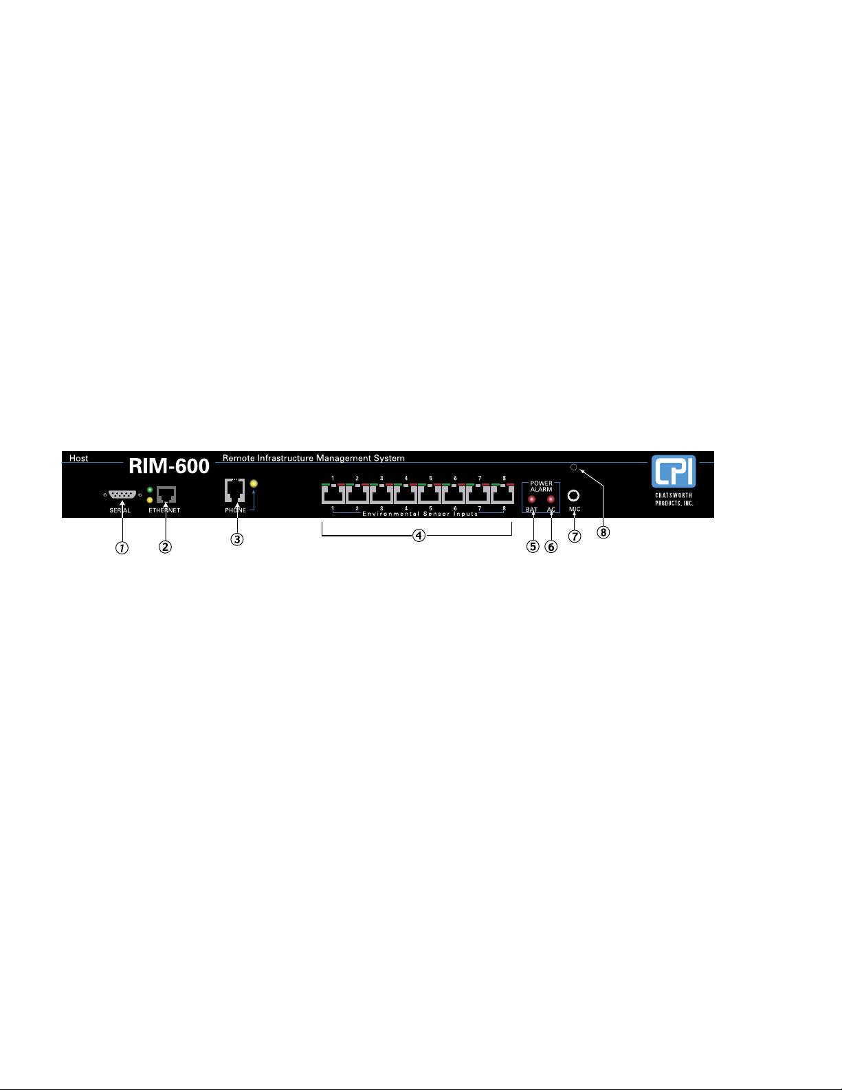
Front Panel Layout
The front panel contains connections for eight sensor inputs, microphone input, Ethernet port, serial
port, and status LEDs. See figure below:
Figure 1: Front Panel Layout of the RIM-600 Host
1 Serial Port
2 Ethernet port (10/100Base-T)
3 Phone line
4 Sensor Inputs (8)
5 Battery Power Alarm LED
6 AC Power Alarm LED
7 External Microphone Input
8 Internal Microphone
Serial Port
The RS-232 serial port is used to configure network settings. The port operates at 9600 baud, no
parity, and 1 stop bit.
RJ-45 10/100BASE-T Ethernet Port
This jack is for connecting to your network so that the RIM-600 Host can communicate with the
RIM-600 Nodes and ping selected network servers and/or services. Two LEDs indicate received
data (green) and transmitted data (yellow).
Phone Jack
Connect the RIM-600’s Phone jack to a standard 2-wire analog phone line. The unit dials using
touch-tones, with loop start only. The RIM-600 will recognize ringer frequencies from 16 to 60 Hz
and will operate with all standard analog telephone systems that accept tone dialing.
2020

Chapter 1: Installation
Chapter 1: Installation
Certain private telephone systems and public switching equipment may not accept the unit’s dialing
or may generate an unacceptable ring signal. In those cases, a dedicated line may be required for
the unit. Consult the supplier of your telephone system if you encounter problems.
CAUTION: Never install telephone wiring during a lightning storm. Never install telephone
jacks in wet locations unless the jack is specifically designed for wet locations. Never touch
uninsulated telephone wires or terminals unless the telephone line has been disconnected at the
network interface. Use caution when installing or modifying telephone lines.
Sensor Inputs
The sensor inputs are designed to interface with
RIM-600 series sensors (See Chapter 7). The use
of RJ-45 jacks for sensor inputs allows the use of existing structured cabling to connect remote sensors.
Since the sensor produces an analog signal, it must connect directly to the Host or Node. The path
from the sensor to the RIM-600 unit CANNOT pass through a network Hub or Switch.
Sensor Input LEDs
Each sensor input has two LEDs (red and green) to indicate the present status of the input. The
key below describes the multiple modes of operation.
Mode 0: No sensor at input
Green: OFF
Red: OFF
Mode 1: Sensor present—No alarms
Green: ON
Red: OFF
Mode 2: Alarm detected but has not exceeded recognition time
Green: FAST BLINK
Red: FAST BLINK
Mode 3: New alarm exists and not yet acknowledged
Green: SLOW BLINK
Red: SLOW BLINK
Mode 4: Input is in normal range, but alarm is still unacknowledged
Green: ON
Red: SLOW BLINK
Mode 5: Alarm has been acknowledged, but input is still out of range
Green: SLOW BLINK
Red: ON
Mode 6: Sensor in trouble
Green: QUICK FLASH
Red: QUICK FLASH
21
21
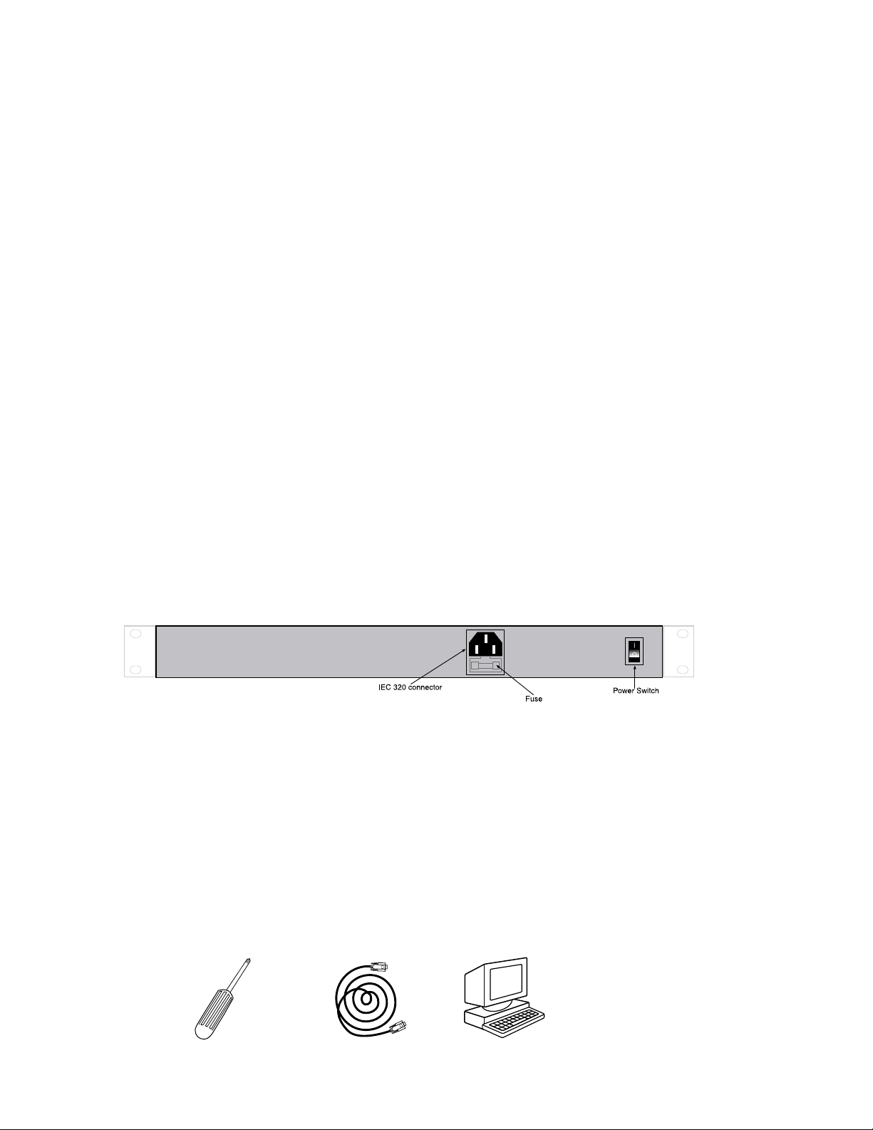
RIM-600 Manual
AC Power and Battery LEDs
The AC Power and Battery alarm status is indicated by two red LEDs. Their modes of operation
are described below.
Mode 1: No Alarm
LED: OFF
Mode 2: Alarm detected but has not exceeded recognition time
LED: FAST BLINK
Mode 3: New Alarm exists and not yet acknowledged
LED: SLOW BLINK
Mode 4: Alarm has been acknowledged but input is still out of range
LED: ON
Microphone Jack
The Host unit comes with a built-in microphone. Directly below the built-in mic is a separate jack
for connecting an optional condenser microphone to sense audible alarms, such as smoke detectors.
When an external microphone is connected, the internal microphone is disabled.
Rear Panel
The rear panel is where the main power switch is located. The main power cord attaches to the
IEC320 connector. The unit can be powered from 90–260VAC 47–63Hz.
ON/OFF Switch
The on/off switch connects main power and battery power to the system. Note that the system will
only turn on when main power is present. When main power fails, the internal battery will auto
matically supply power to the unit.
Figure 2: Rear Panel of the RIM-600 Host
Installation
This section provides information on:
n Operating environment
n Rack, wall, and tabletop installation
n Connecting sensors
-
Parts Required
22
22
Phillips 9 pin F/F null Dumb terminal or PC
Screwdriver modem cable w/9 pin com port
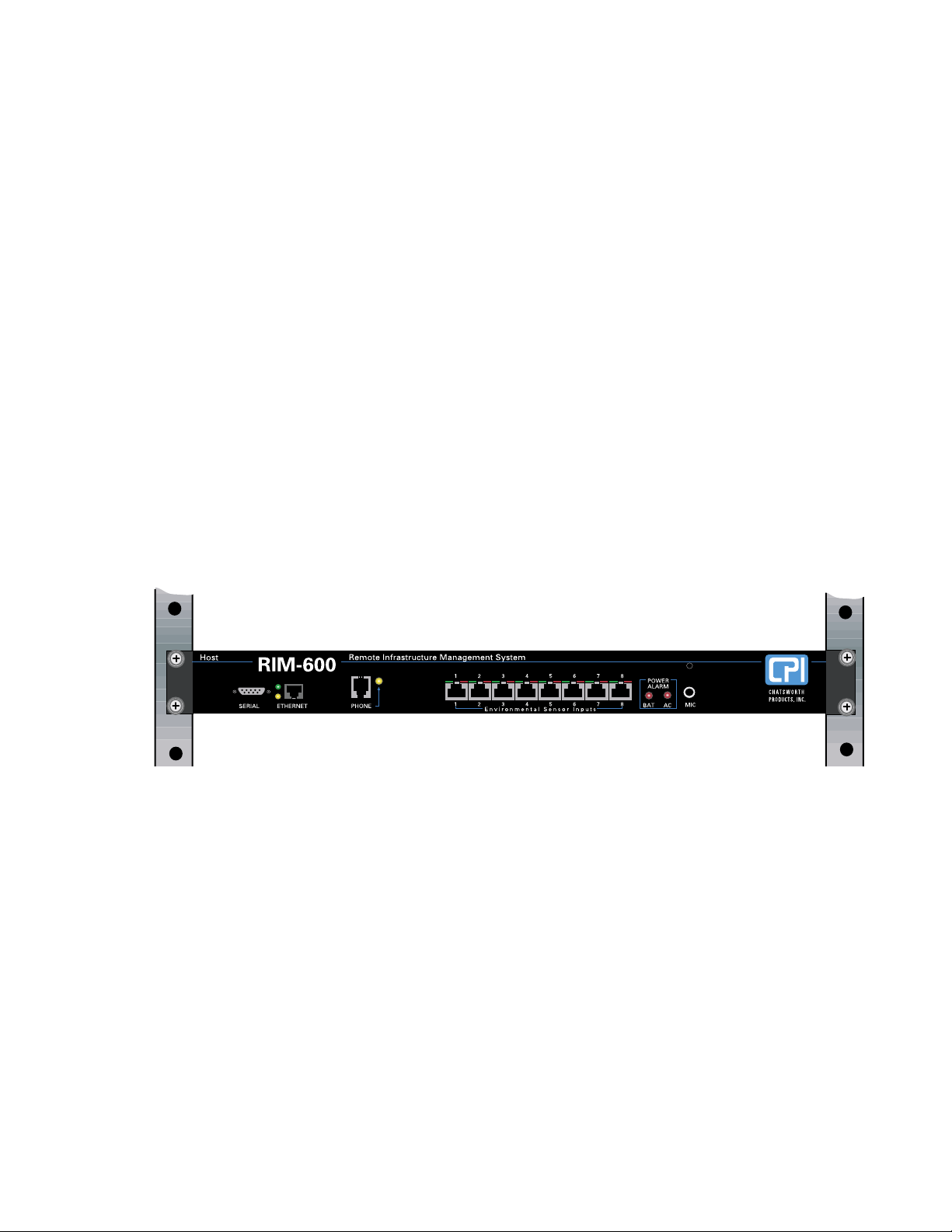
Chapter 1: Installation
Chapter 1: Installation
Operating Environment
Before you install the RIM-600 Host be sure that your operating environment meets the physical
requirements of the equipment.
Operating Temperature: 32º– 122º Fahrenheit (0º–50º C)
Humidity: 5– 90 %RH, non-condensing
Power: 90–260VAC 47/63 Hz outlet within 6'
Rack Requirements: Standard 19
" equipment rack with supplied mounting bracket
hardware. Requires 1.0 EIA rack mount space.
Tabletop requirements: Flat area which can support an enclosure 17" wide by 10" deep by 2"
high.
Rack Mount Installation
The RIM-600 Host can be rack mounted using the included rack mount brackets. Follow the steps
below:
1) Attach rack-mount brackets to the sides of the Host unit with a Phillips screwdriver.
2) Attach the unit to the equipment rack using two pan-head screws per side. Tighten the
screws with a Phillips screwdriver.
3) Plug the power cord into a 90-260VAC outlet.
Figure 3: Rack-mounted Host Unit
Wall Mount Installation
The RIM-600 Host can be wall mounted using the optional wall mount brackets. Follow the steps
below:
1) Attach the optional wall mount brackets to the sides of the
#6-32 screws. A Phillips screwdriver will be required. (Order part # 60075-001 Universal
Wall Mount Kit)
2) Attach the unit to the wall using two screws per side. Tighten the screws with a Phillips
screwdriver.
3) Plug the power cord into a 90-260VAC outlet.
RIM-600 using the eight black
23
23

RIM-600 Manual
Figure 4: Wall-mounted Host Unit
Tabletop Installation
The RIM-600 Host can be installed on a tabletop or shelf. Follow the steps below:
1) Attach the four self-adhesive rubber feet to the four corners on the bottom of the RIM-600.
2) Place the unit on a tabletop or shelf and connect the power cord into a 90-260VAC outlet.
Figure 5: Tabletop-mounted Host Unit
Power On Self Test (POST)
When the power switch is turned on, the red and green input LEDs will begin a blinking pattern to
indicate that the unit is booting up and performing internal diagnostic tests. The unit will also beep
once, 25 seconds after power is applied. When the LEDs stop blinking, the unit is fully booted and
operational. The boot and Power On Self Test take approximately 2 minutes.
Connecting Sensors
The RIM-600 Host has eight sensor inputs. Each input can accept any sensor type. Sensors are
available to monitor the following:
n Temperature n Smoke
n Humidity n Security
n Water detection n Motion
n AC voltage
n Alarm contacts from external equipment
All RIM-600 sensors connect to the Host using standard RJ-45 cables. This makes it easy to connect sensors directly to the unit. Simply plug one end of the cable into the sensor and the other end
into one of the sensor inputs on the Host.
2424

Chapter 1: Installation
Chapter 1: Installation
Another benefit of using RJ-45 connectors is that you can easily locate sensors at distant locations
within your facility by using your existing structured cabling. For example: Suppose you have an
RIM-600 installed in room A and you want to install a sensor in room B. If your existing cabling
infrastructure has an unused cable path between room A and room B, then you simply use an RJ-45
interconnect cable to connect the
RIM-600 to the patch panel in room A, and an RJ-45 interconnect
cable from the wall jack in room B to the sensor.
CAUTION: The sensor produces an analog signal which must connect directly to the Host or
Node. The path from the sensor to the RIM-600 unit CANNOT pass through a network Hub or
Switch.
Network Configuration
The RIM-600 Host has a serial port on the front panel which is used to configure network settings
and security options. A dumb terminal or terminal emulation software is required to get online
and set up the configuration. The port is male DTE, so you will need to use a null modem cable.
Terminal communication settings must be set to:
n 9600 baud, no parity, 8 data bits, 1 stop bit
To get online with the RIM-600, connect your terminal to the serial port and press <RETURN>. A
menu will appear which will guide you through the setup.
RIM-600 Host Unit V1.0.0.0
Enter Password ()>
{The DEFAULT PASSWORD for a New Unit is “rim600”}
1. Display Enterprise status
2. Display Network and Option configuration
3. Configure Network settings
4. Configure Enterprise Name
5. Configure Web Server
6. Configure Remote Access Server
7. Enable Two-Way E-mail Responder
8. Enable Microphone Listen-In
9. Enable default Master Administrator Account (temporarily)
0. Enable data modem
A. Configure SNMP
B. Change Admin Password
C. Reset To Factory Defaults
D. Display Statistics
E. Reboot
F. Logout
Enter option->
If you select Option 1 you will see the IP address and status of the Host and all associated nodes.
A sample is shown below:
25
25

RIM-600 Manual
Enterprise Status
Unit Type IP Status
RIM-600 Monitor Host 10.1.4.10 Ok
NY_Node Node 10.1.4.17 Ok
Press any key to return to main menu
Option 2 will display the network configuration for the Host as well as web server, RAS, and twoway email settings. A sample of Option 2 is shown below:
Network and Option Configuration
Physical Address 00:D0:C9:37:40:86
IP Address 10.1.4.10
Subnet Mask 255.255.255.0
Default Gateway 10.1.4.1
DNS Server 10.1.2.111
Enterprise name RIM-600 Enterprise
Web Server Enabled
Web Server Security Enabled
Web Programming Option Enabled
Web Programming Security Enabled
Remote Access Server Enabled
RAS IP Port Address 0.0.0.0
Two-Way E-mail Responder Enabled
Microphone Listen-in Enabled
Datamodem Enabled
SNMP RO community public
SNMP RW community private
SNMP Agent Enabled
Allow remote configuration Disabled
Press any key to return to main menu
Option 3 will allow you to set all pertinent network settings listed under Option 2.
NOTE: You can remotely reconfigure the Host network settings using the
RIM-600
ConsoleView software if the Allow Remote Configuration option is set to Y. However, the Host
must initially be configured via the serial port before any remote configuration is possible.
Option 4 allows you to configure or reconfigure the Enterprise name.
Option 5 allows you to configure the Web server. When Web security is enabled, a Profile
Username & Password must be entered to view the web page. A sample of the Web configuration
menu is shown below:
Configure Web Server
1. Enable Web Server: Y/N
2. Enable Web Status Security: Y/N
3. Enable Web Programming option: Y/N
4. Enable Web Programming Security: Y/N
26
26
 Loading...