

Chatillon Force Measurement MT500LExBX, MT150LU1B2, MT150LS1BX, MT150LE1B2, MT500LUxBX User manual [en, fr]
...Page 1

Part No. NC002660
August 2014
MT Series - Série MT
Tension/Compression Mechanical Test Stand
Bancs d’essais de traction & compression
User Manual - Manuel d’utilisation
MT Series User Manual 1
Find Quality Products Online at: [email protected]
www.GlobalTestSupply.com
Page 2

PRODUCT WARRANTY
This instrument is warranted against defects in workmanship, material and
design for one (1) year from date of delivery to the extent that AMETEK will,
at its sole option, repair or replace the instrument or any part thereof which is
defective, provided, however, that this warranty shall not apply to instruments
subjected to tampering or abuse, or exposed to highly corrosive conditions.
THIS WARRANTY IS IN LIEU OF ALL OTHER WARRANTIES WHETHER EXPRESS OR IMPLIED AND AMETEK HEREBY DISCLAIMS ALL OTHER WARRANTIES, INCLUDING, WITHOUT LIMITATION, ANY WARRANTY OF FITNESS
FOR A PARTICULAR PURPOSE OR MERCHANTABILITY. AMETEK SHALL NOT
BE LIABLE FOR ANY INCIDENTAL OR CONSEQUENTIAL DAMAGES INCLUDING, BUT NOT LIMITED TO, ANY ANTICIPATED OR LOSS PROFITS.
This warranty is voidable if the purchaser fails to follow any and all instructions,
warnings, and cautions in the instrument’s Instruction Manual.
If a manufacturing defect is found, AMETEK will replace or repair the instrument
or replace any defective part thereof without charge; however, AMETEK’s obligation hereunder does not include the cost of transportation which must be borne
by the customer. AMETEK assumes no responsibility for damage in transit, and
any claims for such damage should be presented to the carrier by the purchaser.
GARANTIE DU PRODUIT
Cet instrument est garanti contre tout défaut de fabrication pour un an (1),
pièces et main-d’œuvre. Cette garantie ne s’applique pas si l’appareil a été soumis à une tentative de réparation, à une mauvaise utilisation, ou s’il a été exposé
à des conditions fortement corrosives.
CETTE GARANTIE REMPLACE TOUTES AUTRES GARANTIES QUELLES
QU’ELLES SOIENT. AMETEK NE SERA PAS TENU RESPONSABLE DES DOMMAGES CONSECUTIFS A L’UTILISATION DU MATERIEL QUI ENTRAINERAIT
UNE PERTE D’EXPLOITATION EVENTUELLE.
Cette garantie ne s’applique pas si l’acheteur ne tient pas compte des avertissements et précautions décrits dans le présent manuel d’utilisation.
Si un défaut de fabrication est trouvé, AMETEK remplace ou répare l’appareil,
ou toutes pièces défectueuses sans frais ; cependant l’engagement de AMETEK ci-dessus n’inclut pas les frais de transports qui doivent être payés par le
client. AMETEK n’assume aucune responsabilité de possibles dommages lors
du transport, et toutes les réclamations pour de tels dommages devraient être
présentés au transporteur par l’acheteur.
2 MT Series User Manual
Find Quality Products Online at: [email protected]
www.GlobalTestSupply.com
Page 3

TABLE OF CONTENTS / TABLE DES MATIERES
1.0 Introduction ......................................... 4
2.0 Specifications ..................................... 4
2.1 Capacities ............................................. 4
2.2 Drive Mechanism .................................. 4
2.3 Travel Rate ........................................... 4
2.4 Total Column Length ............................ 4
2.5 Stroke .................................................... 4
2.6 Throat Depth ......................................... 4
2.7 MT Weight ............................................. 4
3.0 Assembly & Spare Parts .................... 4
3.1 Bench/Wall Mounting ........................... 4
3.2 Force Gauge Mounting Kits ................. 5
3.3 Ruler Assembly Kit ............................... 6
3.4 Digital Indicator Assembly Kit .............. 7
3.5 Horizontal/Wall Mounting Kit ............... 8
3.6 Additional Spare Part Kits .................... 9
3.6.1 Load Actuation Assemblies ................. 9
3.6.2 Misc. Spare Parts ................................. 9
4.0 Standard accessories ........................ 9
5.0 Compression Testing Procedure .. 10
6.0 Tension Testing Procedure ........... 11
1.0 Intruduction ................................... 20
2.0 Specifications ............................... 20
2.1 Capacités ....................................... 20
2.2 Mécanisme d’utilisation ................. 20
2.3 Précision du déplacement ............. 20
2.4 Longueur de colonne ..................... 20
2.5 Crémaillère ..................................... 20
2.6 Profondeur du débattement ........... 20
2.7 Poids du banc MT .......................... 20
3.0 Kit de Montage et accessoires ... 20
3.1 Montage sur établit ou mur ............ 20
3.2 Kit de montage de dynamomètre .. 21
3.3 Kit de montage de la règle ............. 22
3.4 Kit de montage de l’indicateur numérique .. 23
3.5 Kit de montage horizontal ou mural ..... 24
3.6 Kit d’accesoires supplémentaires .. 25
3.6.1 Méchanisme d’utilisation ............... 25
3.6.2 Accessoires divers ......................... 25
4.0 Accessoires Standard ................... 25
5.0 Procedure de Test en Compression .. 26
6.0 Procedure de Test en Tension ....... 27
7.0 Repair of MT Test Stand ................ 11
8.0 Parts list ............................................. 12
7.0 Entretien du Banc de Test MT ....... 27
8.0 List des Pieces Detachees ............ 28
MT Series User Manual 3
Find Quality Products Online at: [email protected]
www.GlobalTestSupply.com
Page 4

1.0 INTRODUCTION
The CHATILLON MT test stand is designed to perform various tension or compression tests
utilizing the full range of CHATILLON force gauges. The MT test stand has two available
capacities 150 LBF (660 N) and 500 LBF (2.2 KN). Each capacity has a quick-action lever or
precision hand-wheel operating mechanism available. The MT test stand can be positioned
vertically and mounted to a bench or wall mounted. The MT test stand can also be horizontally mounted and fastened to a bench. The wall mounting and horizontal mounting utilize
the same components. The MT column comes in three selectable heights 750mm, 1000mm
and 1500mm to accommodate various test sample heights. A ruler assembly is available for
measurements that require minimal travel accuracy. A digital indicator is available for measurements that require accurate travel measurements. The MT test stand is lightweight and
modular in design. The MT test stand comes with standard accessories that will allow many
CHATILLON and LLOYD grips and fixtures to adapt to the test stand.
2.0 SPECIFICATION
2.1 Capacities 150 LBF (660 N)
500 LBF (2.2 KN)
2.2 Drive Mechanism Quick-Action Lever
Precision Hand-Wheel
2.3 Travel Rate Quick-Action Lever – 75 mm (3 in) per Rev
Precision Hand-Wheel – 12 mm (0.5 in) per Rev
2.4 Total Column Length Standard – 750 mm (29.5 in)
Extended – 1000 mm (39.4 in)
Ultra – 1500 mm (59.1 in)
2.5 Stroke 150 mm (6 in)
2.6 Throat Depth 150 mm (6 in)
2.7 MT Weight 12.2 KG (26 LB) approx. weight
3.0 ASSEMBLY AND SPARE PARTS LIST
3.1 Bench/Wall Mounting
Place MT test stand on a firm, flat level work surface that is free from vibration to ensure
accurate readings. It is recommended that the MT test stand is vertically mounted to a
work bench utilizing the four Ø8 mm (Ø.31 in) holes in the base. For horizontal or wall
mounting there are four Ø8.5mm (Ø.33 in) holes in two mounting plates that are used for
mounting the MT test stand to a bench or wall.
4 MT Series User Manual
Find Quality Products Online at: [email protected]
www.GlobalTestSupply.com
Page 5
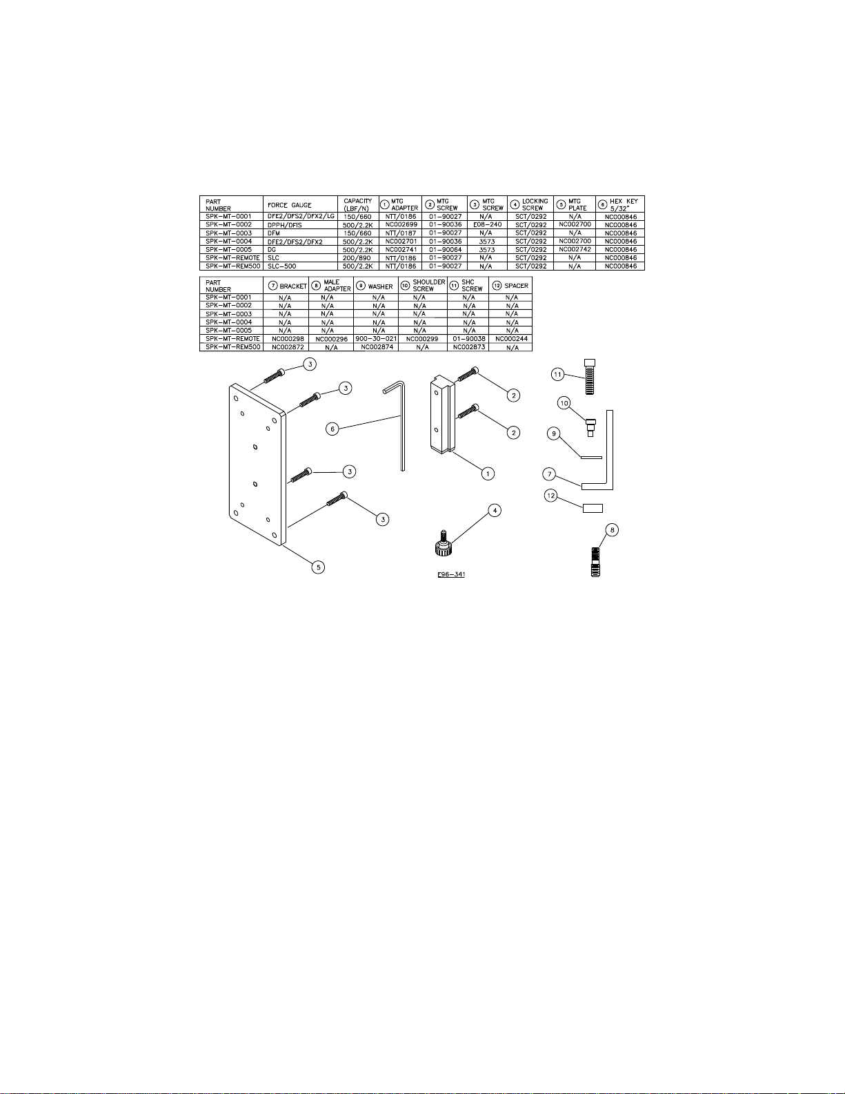
3.2 Force Gauge Mounting Kits
When ordering a force gauge mounting kit the parts shown in FIGURE 1 will be supplied
as indicated. For DFE2/DFS2/DFX2 Series Gauges use SPK-MT-0001 mounting kit from 0
to 150 LBF testing and use SPK-MT-0004 mounting kit for 150 to 500 LBF testing.
MT Series User Manual 5
Find Quality Products Online at: [email protected]
www.GlobalTestSupply.com
Page 6
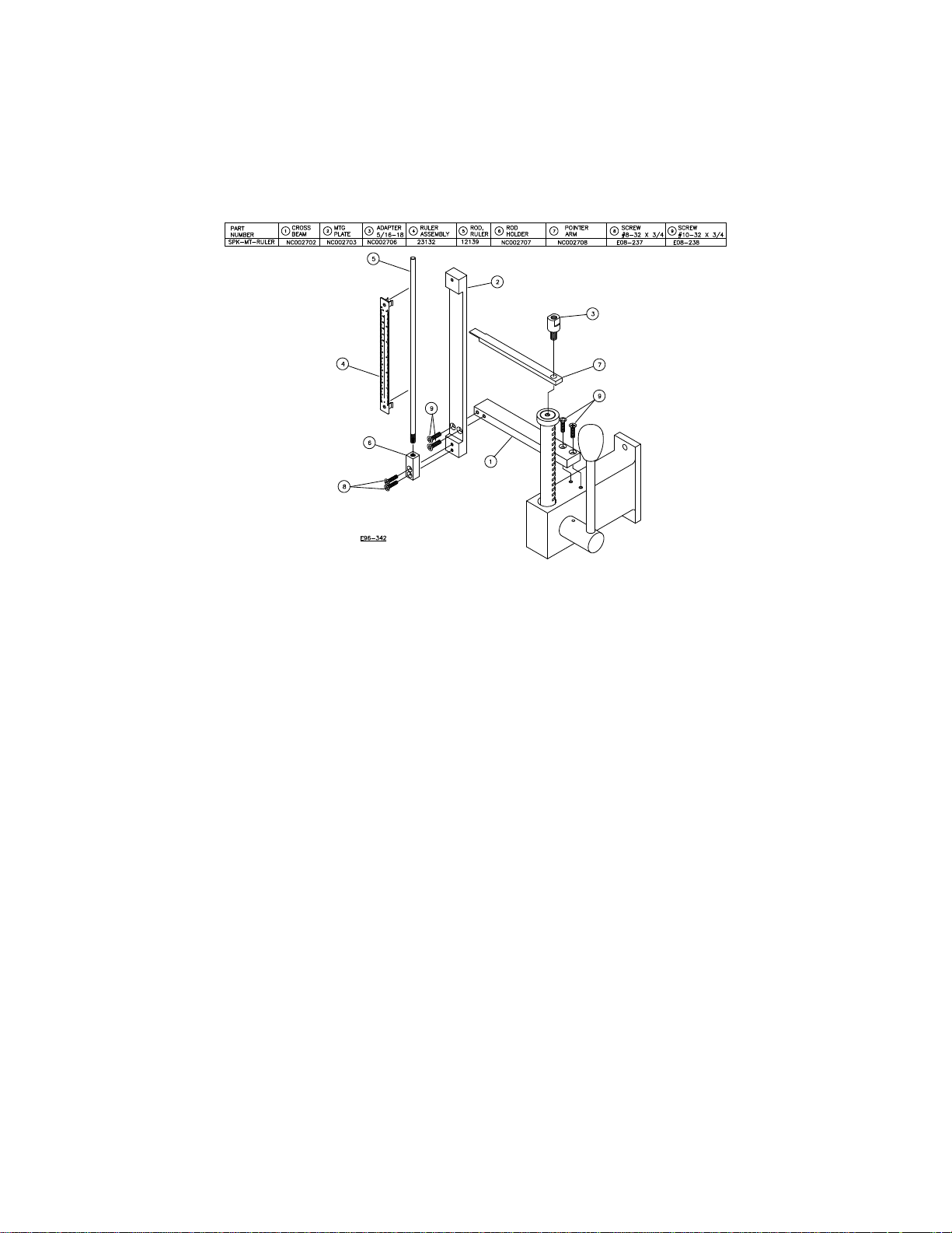
3.3 Ruler Assembly Kit
The ruler assembly instructions are as follows:
3.3.1 Assemble CROSS BEAM (Item 1) to top of lever or hand-wheel assembly of MT
test stand using two SCREWS (Item 9).
3.3.2 Assemble MTG PLATE (Item 2) to CROSS BEAM (Item 1) using two SCREWS
(Item 9).
3.3.3 Thread RULER ROD (Item 5) to ROD HOLDER (Item 6).
3.3.4 Assemble ROD HOLDER (Item 6) to MTG PLATE (Item 2) using two SCREWS
(Item 8).
3.3.5 Press on RULER ASSEMBLY (Item 4) to RULER ROD (Item 5).
3.3.6 Assemble POINTER ARM (Item 7) to movable RACK on MT test stand using
5/16-18 ADAPTER (Item 3). The pointer arm should be located in front of the ruler
assembly.
6 MT Series User Manual
Find Quality Products Online at: [email protected]
www.GlobalTestSupply.com
Page 7
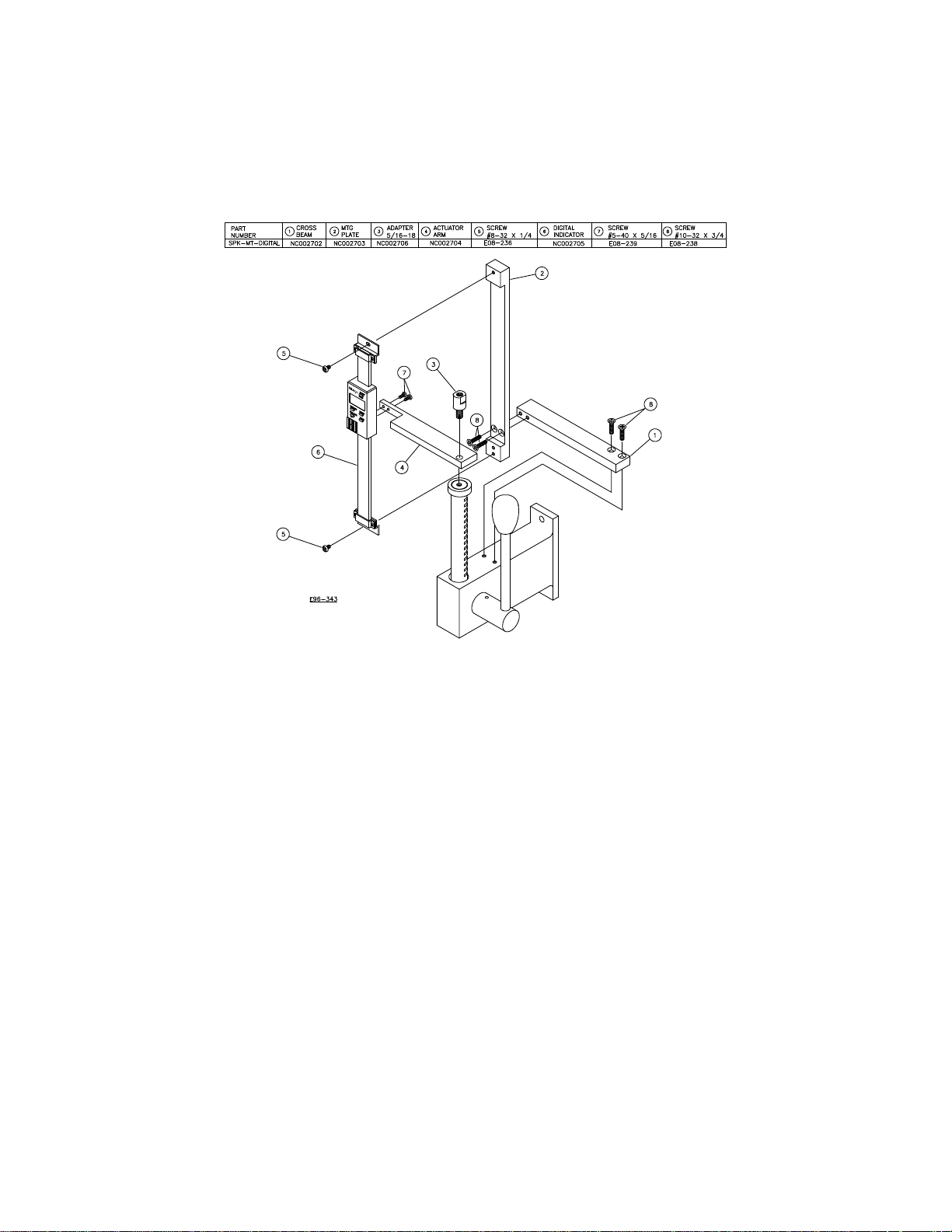
3.4 Digital Indicator Assembly Kit
The digital indicator assembly instructions are as follows:
3.4.1 Assemble CROSS BEAM (Item 1) to top of lever or hand-wheel assembly of MT
test stand using two SCREWS (Item 8).
3.4.2 Assemble MTG PLATE (Item 2) to CROSS BEAM (Item 1) using two SCREWS
(Item 8).
3.4.3 Assemble ACTUATOR ARM (Item 4) to the lower two screw holes of the DIGITAL
INDICATOR (Item 6) using two SCREWS (Item 7).
3.4.4 Assemble DIGITAL INDICATOR (Item 6) to MTG PLATE (Item 2) using two
SCREWS (Item 5).
3.4.5 Assemble ACTUATOR ARM (Item 4) to movable RACK on MT teststand using
5/16-18 ADAPTER (Item 3).
MT Series User Manual 7
Find Quality Products Online at: [email protected]
www.GlobalTestSupply.com
Page 8
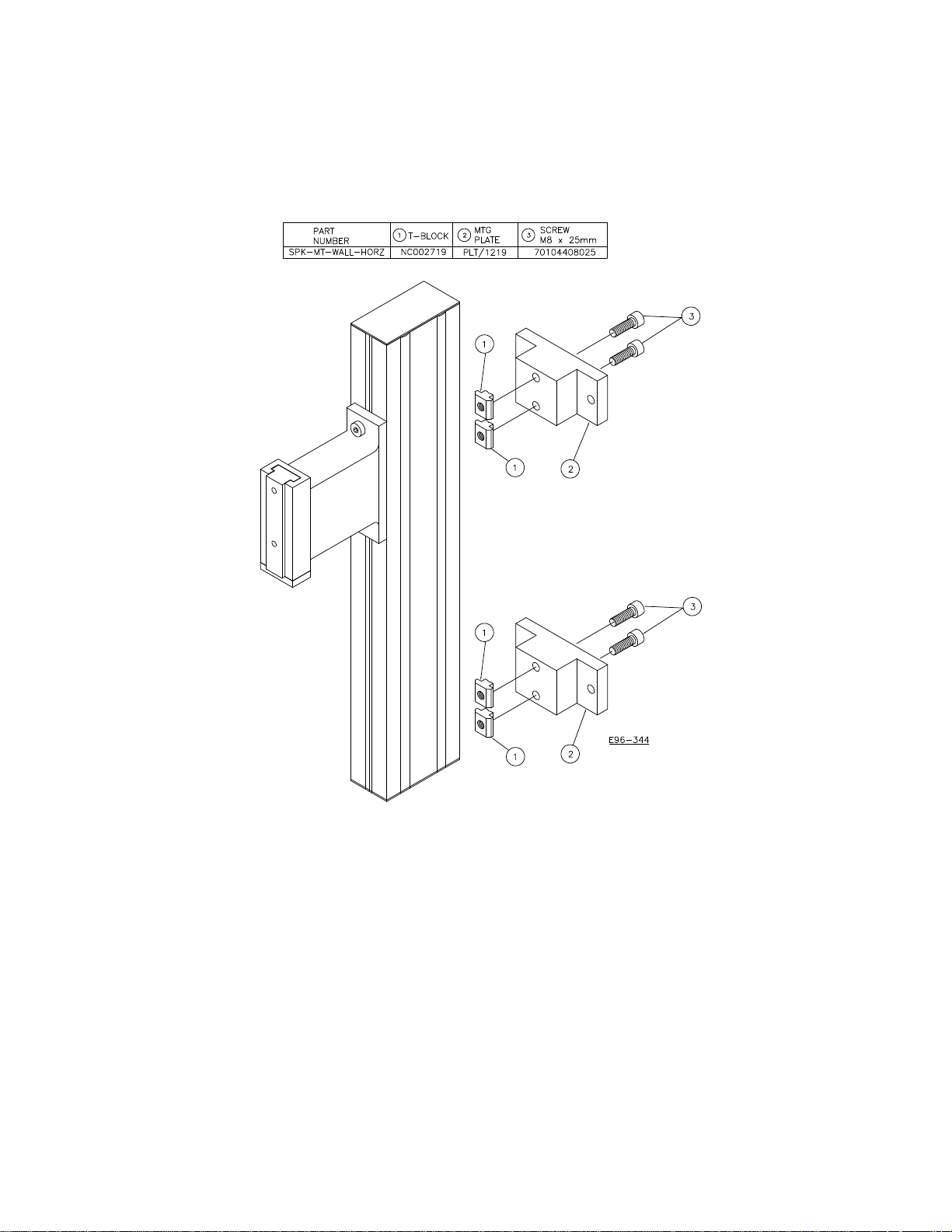
3.5 Horizontal / Wall Mounting Kit
The Horizontal/Wall mounting assembly instructions are as follows:
3.5.1 Remove top plastic cap from top of column using a small screw driver.
3.5.2 Assemble two SCREWS (Item 3) to MTG PLATE (Item 2) and thread
on two LONG NUTS (Item 1).
3.5.3 Slide bottom mounting plate assembly to lower part of the MT test stand
column and fully tighten two screws using a 6mm hex key.
3.5.4 Repeat step 3.5.2 for the top mounting plate assembly.
3.5.5 Slide top mounting plate assembly to upper part of the MT test stand
column and fully tighten two screws using a 6mm hex key.
3.5.6 The four Ø8.5mm (Ø.33 in) holes in the two mounting plates are used for
mounting the MT test stand to a bench (horizontally) or wall (vertically).
3.5.7 Replace the top plastic cap to the column by pressing it on.
8 MT Series User Manual
Find Quality Products Online at: [email protected]
www.GlobalTestSupply.com
Page 9

3.6 Additional Spare Parts
3.6.1. Load Actuation Assemblies
SPK-MT-L150 Lever Actuation Model, 150 LB/660 N
SPK-MT-L500 Lever Actuation Model, 500 LB/2.2 KN
SPK-MT-H150 Hand Wheel Actuation Model, 150 LB/660 N
SPK-MT-H500 Hand Wheel Actuation Model, 500 LB/2.2 KN
3.6.2. Miscellaneous Spare Parts
SPK-MT-REMOTE Remote load cell MTG kit (0.55 LB/250 G to 200 LB/890 N)
SPK-MT-REM500 Remote load cell MTG kit (500 LB/2.2 KN)
4.0 STANDARD ACCESSORIES
The Standard accessories that come with the MT test stand are as follows:
NC000714 Hex Key, 6mm
NC002660 Operation Manual
SPK-FMG-012B Hook Assembly, 150 LB (STD with 150 LB test stand)
SPK-FMG-012C Hook Assembly, 500 LB (STD with 500 LB test stand)
17012 Compression Platen, Ø3 in
NC002686 Set Screw, 5/16-18 X 1 in
P-10020 Adapter, 5/16-18 M to #10-32 F (STD with 150 LB test stand)
NC002292 Registration Card
13048 Coupling, 1/4-28 F to 5/16-18 F
ADT/0115 5/16-18 F to 5/8 in Eye End
3157 Set Screw, #10-32 X 3/4 in (STD with 150 LB test stand)
MT Series User Manual 9
Find Quality Products Online at: [email protected]
www.GlobalTestSupply.com
Page 10
5.0 COMPRESSION TESTING PROCEDURE
5.1. Establish the platform location in reference to its travel so that the deflection
requirements for the test to be made will be accomplished before the platform
reaches the limit of its stroke. For example: if the test requires 2 inches of deflection, ensure the platform will travel the required 2 inches before stopping. Allow
additional travel for the deflection of the force gauge.
5.2. Center the test specimen on platform and adjust height of force gauge above
platform to desired height using the 6mm hex key provided.
5.3. If deflection measurements using the ruler assembly are required, take note of
reading on ruler when gauge plate touches the test specimen. This point can
be determined by monitoring the force gauge indicator while slowly raising the
platform. Stop the platform travel the moment a force is registered on the gauge
and then back off very slightly. At this point, note the reading on the ruler. The
ruler may be adjusted on the rod to line up with the pointer for easier reading. The
CHATILLON force gauges have different deflection and this must be accounted
for when taking deflection measurements. Refer to TABLE 1 for deflection of each
model gauge at full scale. Example: If A DPP 50 LB gauge was loaded at 50 LB
(full scale) and the deflection on the ruler indicated 2.0 inches, the true movement
of the sample was 1.9 inches due to the shaft of the DPP force gauge moving 0.1
inches.
Gauge Model Load Cell/Spring Deflection
DPP, DPPH .100 inches at full scale (1 revolution)
LG/DG 10mm (.394 inches) at full scale (1 revolution)
DFM .015 inches at full scale
DFIS/DFE2/DFS2/DFX2 .007 inches at full scale
DFGS integral load cell .010 inches at full scale
DFS-R 250 g to 10 LB .015 inches at full scale
DFS-R 50 LB to 500 LB .008 inches at full scale
TABLE 1
5.4. When using the digital indicator it is necessary to compensate for deflection of the
force gauge when performing a compression test. To obtain the true deflection
of the test specimen refer to TABLE 1 for the full scale deflection for each force
gauge model. Example: If A DPP 50 LB gauge was loaded at 25 LB (half scale)
and the deflection on the digital indicator was 2.000 inches, the true movement of
the sample was 1.950 inches due to the shaft of the DPP force gauge moving .05
inches.
10 MT Series User Manual
Find Quality Products Online at: [email protected]
www.GlobalTestSupply.com
Page 11

6.0 TENSION TESTING PROCEDURE
6.1. Establish the platform location in reference to its travel so that the deflection
requirements for the test to be made will be accomplished before the platform
reaches the limit of its stroke. For example: if the test requires 2 inches of deflection, ensure the platform will travel the required 2 inches before stopping. Allow
additional travel for the deflection of the force gauge.
6.2. Place test specimen in upper grip or hook and zero the force gauge. Then attach
test specimen to lower grip or hook.
6.3. If deflection measurements using the ruler assembly are required, take note of
reading on ruler when the test specimen is taut between the grips or hooks. This
point can be determined by monitoring the force gauge indicator while slowly
lowering the lower grip or hook. Stop the platform travel the moment a force is
registered on the gauge and then back off very slightly. At this point, note the
reading on the ruler. The ruler may be adjusted on the rod to line up with the
pointer for easier reading. The CHATILLON force gauges have different deflection
and this must be accounted for when taking deflection measurements. Refer to
TABLE 1 for deflection of each model gauge at full scale. Example: If A DPP 50 LB
gauge was loaded at 50 LB (full scale) and the deflection on the ruler indicated 2.0
inches, the true movement of the sample was 1.9 inches due to the shaft of the
DPP force gauge moving 0.1 inches.
6.4. When using the digital indicator it is necessary to compensate for deflection of
the force gauge when performing a tension test. To obtain the true deflection
of the test specimen refer to TABLE 1 for the full scale deflection for each force
gauge model. Example: If A DPP 50 LB gauge was loaded at 25 LB (half scale)
and the deflection on the digital indicator was 2.000 inches, the true movement of
the sample was 1.950 inches due to the shaft of the DPP force gauge moving .05
inches.
7. REPAIR OF MT TEST STAND
If MT test stand becomes damaged, please contact a local AMETEK distributor to obtain
spare parts or repair service.
MT Series User Manual 11
Find Quality Products Online at: [email protected]
www.GlobalTestSupply.com
Page 12
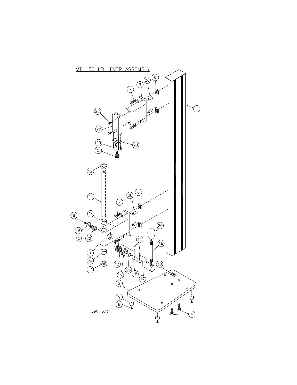
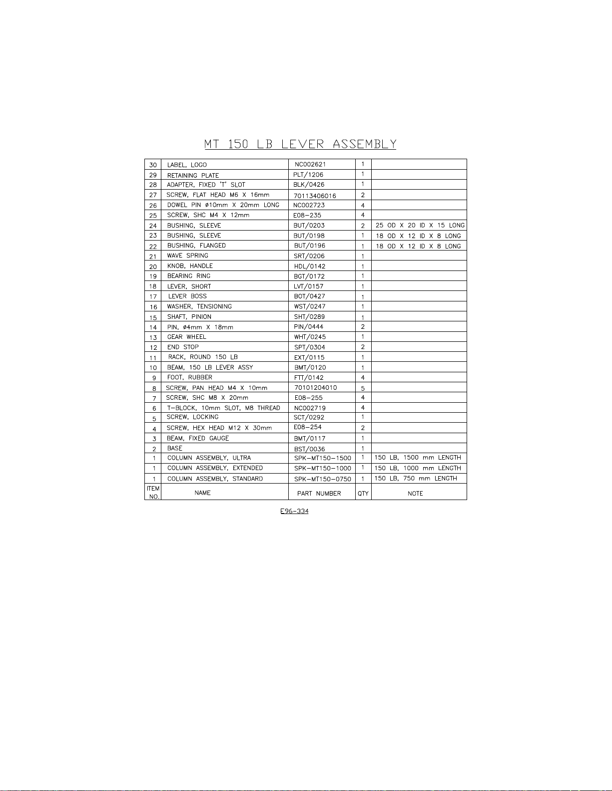
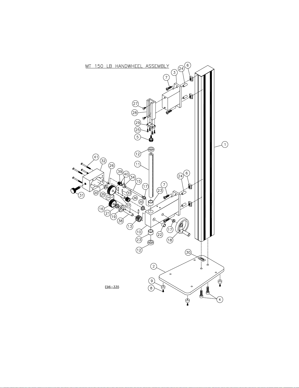
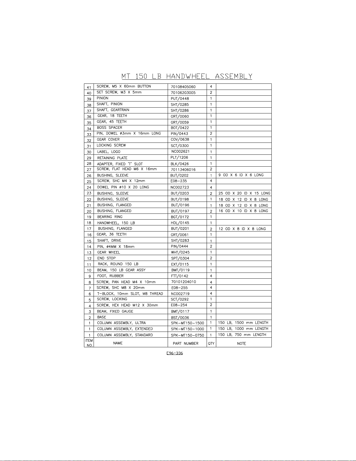
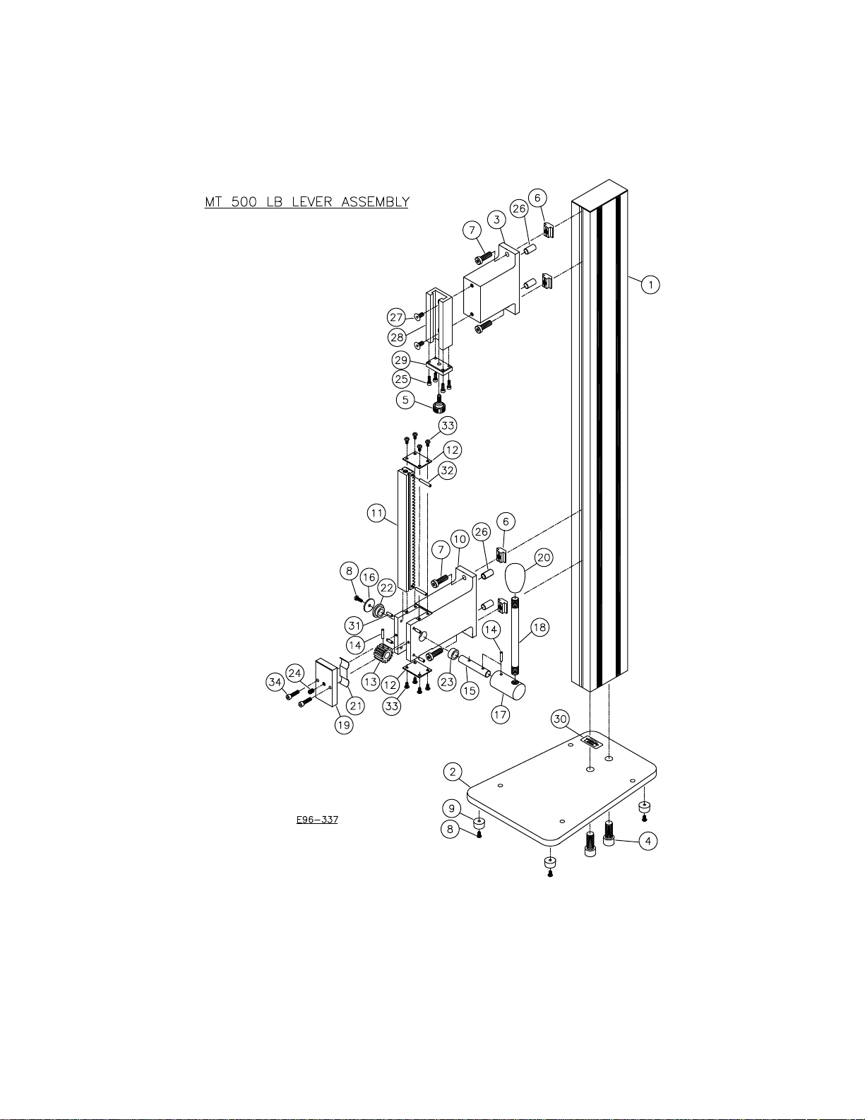
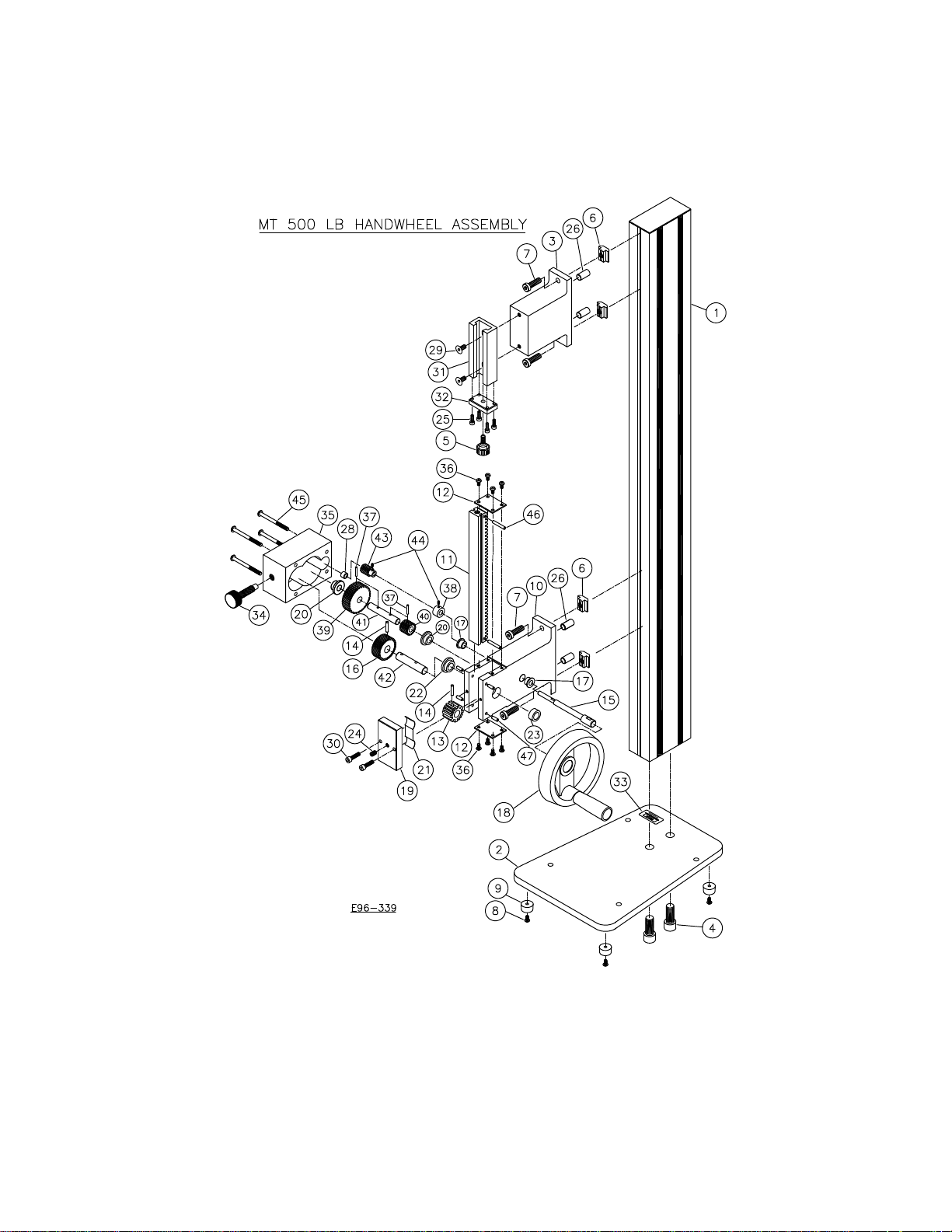
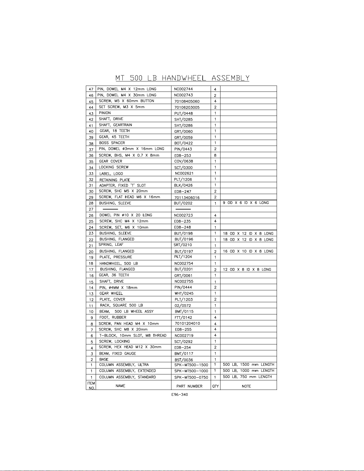
8. PRTS LIST
12 MT Series User Manual
Find Quality Products Online at: [email protected]
www.GlobalTestSupply.com
Page 13
MT Series User Manual 13
Find Quality Products Online at: [email protected]
www.GlobalTestSupply.com
Page 14
14 MT Series User Manual
Find Quality Products Online at: [email protected]
www.GlobalTestSupply.com
Page 15
MT Series User Manual 15
Find Quality Products Online at: [email protected]
www.GlobalTestSupply.com
Page 16
16 MT Series User Manual
Find Quality Products Online at: [email protected]
www.GlobalTestSupply.com
Page 17

MT Series User Manual 17
Find Quality Products Online at: [email protected]
www.GlobalTestSupply.com
Page 18
18 MT Series User Manual
Find Quality Products Online at: [email protected]
www.GlobalTestSupply.com
Page 19
MT Series User Manual 19
Find Quality Products Online at: [email protected]
www.GlobalTestSupply.com
 Loading...