

Page 1
Page 1
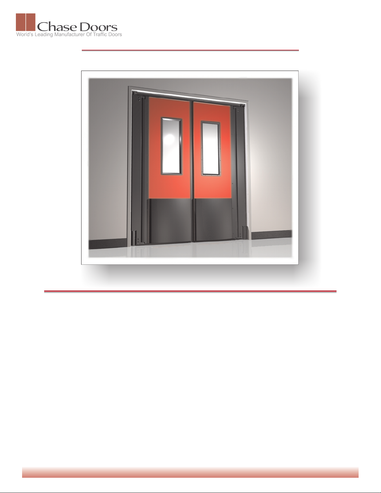
Durulite Evolution XLD360 Installation Instructions
}
DWG # 4002 • DATE: 06-25-08
Preparation
Measure width and height of framed opening and
compare with dimensions given at the time of ordering.
See Figure 1, Page 2 for instructions on testing for a
Square, Level and Plumb Opening.
NOTE: The Durulite® XLD360 doors are constructed
using the dimensions given by the customer when
ordering and are not adapted to fit into a different
sized opening!
Framed openings must meet the dimensions given on
the order received by Chase Doors within the following
tolerances:
SINGLE PANELS
Height: +1/4” -1/4”
Width: +1/4” -1/4”
IMPORTANT: Contact the factory if the dimensions of
your opening do not match the dimensions used for
ordering your panels within the specified tolerances.
DO NOT Continue with installation!
IMPORTANT: ALL CHASE PRODUCTS MUST BE INSTALLED PLUMB AND LEVEL IN A SQUARE OPENING FOR PROPER OPERATION!
Cincinnati OH, and Redmond OR • Phone Toll Free: 1.800.543.4455 • Fax: 1.800.285.0126 • www.chasedoors.com
Cincinnati OH, and Redmond OR • Phone Toll Free: 1.800.543.4455 • Fax: 1.800.285.0126 • www.chasedoors.com
DOUBLE PANELS
Height: +1/4” -1/4”
Width: +1/2” -1/2”
Tools Required
The following tools should be readily available for use
when installing the Durulite® XLD360 Doors:
1) Level
2) Tape Measure
3) Framing Square
4) Phillips Screwdriver
5) Hammer
6) Drill
7) Drill Driver or Rachet
8) 6” Rachet Extension
9) 5/16”, 3/8” & 7/16” Sockets
10) 3/8” Masonry Drill Bit
11) Drill Bits for your application
A] 1/8” Bit for Steel Jambs up to 3/8” Thick
B] 13/64” Bit for Steel Jambs over 3/8” Thick
C] 3/16” Bit for Wood Jambs
D] 5/16” Bit for Drilling and Pinning Lower Hinge
12) 3/16” Allen Wrench (Provided)
13) Center Punch
14) Safety Glasses
It is always recommended that you use protective eye-wear
when installing Chase Doors.
Page 2
Page 2
Durulite Evolution XLD360 Installation Instructions - Continued
}
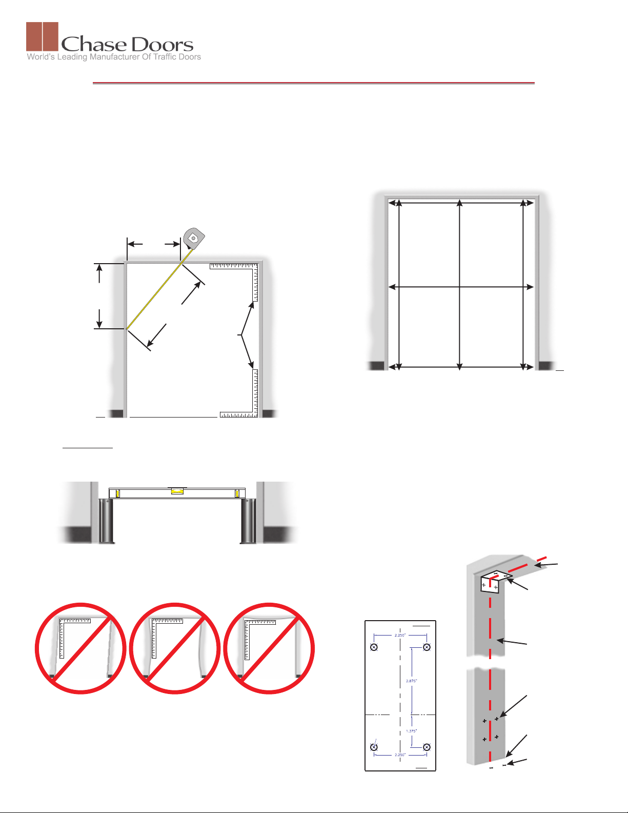
Checking for Square & Plumb Frame
You can check the Upper and Lower Corners of your opening with
a Framing Square, See Figure 1. If you do not have access to a
square then you can use what is commonly known as the “3, 4, 5
Method”.
To Perform the 3, 4, 5 Method (Refer to Figure 1):
Begin by measuring out horizontally from the corner and make a
slight mark at 3’ (Measurement # 1).
From the same corner measure down vertically and make a mark
at 4’ (Measurement # 2).
If the Frame is Square then the measurement between the two
marks (Measurement # 3) will be 5’. If the measurement is not 5’,
then your frame is not square and your doors may not work
properly.
Measurement # 1
3’
Measurement # 2Measurement # 2
4’
Measurement # 3
5’
Framing Square
DWG # 4002 • DATE: 06-25-08
Measuring Your Frame
There are commonly 6 Points of Measurement to assure that your
frame is square, See Figure 3.
If any of these measurements vary by more than 1/4” the doors will
not work properly.
NOTE: The use of any shim material to correct your opening
may cause gaskets to not seal properly. Longer Gaskets may be
available, contact the factory for assistance.
F.F.L.
Figure 1- A
IMPORTANT: If you are installing double panels, it is extremely
important that the Jamb Guards be level with one another for
proper operation, see Figure 1 - B. Un-level floors may require
shims (provided) to be placed under one Jamb Guard.
Doors Must Be Installed Level
for Proper Operation!
Figure 1- B
If any of the conditions in Figure 2-A apply to your opening and
are out of tolerance by more than what is defined in Figure 2-B,
then you will have to rework or replace the frame before installing
Chase Doors.
Figure 3
F.F.L.
Before You Begin Installation
Remove door panel from container. Do NOT remove lumber that binds
the upper and lower hinges together at this time, See Figure 5 - Page 3.
Locate the Hardware Fasteners, Top Seal and Upper Hinge Template. If
any of these items are missing please contact the Customer Service
Department at Chase Doors.
Installing the Durulite XLD360
1)
Locate the Upper Hinge Template, See Figure 4-A. Fold Template
at 90° as indicated on the template. Place template in upper most
corner of Frame and center with jamb & header as shown in
Figure 4-B. Secure with tape. Place a center punch at the center
point of the circles indicated on the template and strike the center
punch with a hammer. Remove the template from the frame and
drill holes at the marks with the appropriate sized bit indicated on
the template.
NOTE: You may need to adjust
your template if there is a Fillet
Weld in the corner of the Jamb.
Measurements on template are
taken from the face of the Jamb
& the face of the Header.
TAPE THIS EDGE TO HEADER
Upper Hinge
Template
Jamb
Header
Figure 2- A
Framed openings must meet the dimensions given on the order
received by Chase Doors within the following tolerances:
SINGLE PANELS
Height: +1/4” -1/4”
Width: +1/4” -1/4”
DOUBLE PANELS
Height: +1/4” -1/4”
Width: +1/2” -1/2”
Figure 2- B
CENTER LINECENTER LINE
JAMB & HEADER
CENTER THIS LINE WITH
3/8" Thick & Over, USE: 13/64" Drill Bit
For Steel Jambs
For Wood Jambs
Up To 3/8" Thick, USE: 1/8" Drill Bit
Use: 3/16" Drill Bit
DRILL BIT SIZES
FOLD UP 90°
MARK @ CENTER
OF HOLES
TAPE THIS EDGE TO JAMB
For Steel Jamb
For Wood Jamb
Use: 1/4" X 1" TEK Screw
Use: 1/4" X 2" HW Screw
FASTENERS
Figure 4-A Figure 4-B
Use 8” Jamb
Guard for
Template
Finished Floor
Line
Mark & Drill for
Anchor Bolts
Page 3

Page 3
Durulite Evolution XLD360 Installation Instructions - Continued
}
Installing the Durulite XLD360 Continued
Carefully remove the 1 X 4 wood
2)
member that holds the upper &
lower hinges in place, beginning
with the fasteners at the Top.
Remove the fasteners from the
lower jamb guard and remove the
Lower Hinge system from the
panel.
NOTE: If the Upper Hinge
Assembly should come apart
before installation refer to page 4
for assistance in reassembling
the hinge. The hinge must have
all parts listed on page 4 to work
properly. If any part is damaged
or missing call the factory
immediately.
Remove 1 X 4 Wood Member
from the Back of the Door
Assembly and discard. Begin
disassembly by removing
the Fasteners that secure the
Top Hinge Assembly.
Locate and remove the Lower Jamb Guard (See Figure 6) from
3)
the hinge assembly. Place the Jamb Guard on the floor at the
lower corner of the jamb, See Figure 6.
NOTE: If a flooring material is to be added later you will need
to make the proper vertical adjustments prior to marking and
drilling the mounting holes. Before marking and drilling holes
for mounting the hardware, double check opening height with
the opening height used when placing order. If there are any
variations your panels may not work properly. Please contact
factory for assistance if your opening differs from the opening
measurements used to order panels.
Center the Jamb Guard with the Jamb as seen in Figure 6.
Secure the Jamb Guard to jamb and floor with tape.
Use a Center Punch and Hammer to mark the center of the
mounting holes on the jamb as done in the previous step.
Check to see that the jamb guard has not moved before
marking each hole.
Figure 5
DWG # 4002 • DATE: 06-25-08
Mark the center point of the holes at the base of the jamb guard
for inserting floor anchors.
Remove Jamb Guard from jamb and set aside.
Use the same drill bit on the jamb as required in the previous step.
You will need a 3/8” Masonry Bit to drill for the Floor Anchors.
Once all the mounting holes have been marked and drilled,
4)
reassemble the hinge system by lifting the door panel and placing
the spine onto the cam as shown in Figure 7.
Figure 7
Stand the door panel up and slide into the opening as near to the
5)
mounting holes as possible.
Carefully remove the Retaining Screw from the upper hinge
assembly using a phillips screwdriver, See Figure 8.
Keep Fingers away from the top of the hinge!
Line up the upper and lower hinges with the mounting holes.
Begin with the Top Hinge and insert and firmly tighten the
appropriate fasteners for your jamb material. Insert fasteners into
the jamb guard and firmly tighten.
Insert floor anchors as instructed on Anchor Package.
Finished Floor
Line
CENTER LINECENTER LINE
Figure 6
Header
Jamb
Use 8” Jamb
Guard for
Template
Mark & Drill for
3/8” Anchor Bolts
Figure 8
IMPORTANT NOTE
THE JAMB GUARD MUST BE PINNED FOR PROPER OPERATION!
Through Jamb Guard
The “Pinning” Process and Step 6 of
Loosen the Setscrews that have been installed in the Lower Jamb
Guard, See Figure 9. Set the door to the center position and firmly
these instructions has been removed.
tighten the setscrew on one side of the Jamb Guard. Open door
These doors are now “Pinned” in the
enough to give you access to the center setscrew and tighten firmly.
Make sure that the door is still in the centered position. Remove the
setscrew on the side and Drill a 5/16” hole completely through the
Jamb Guard and Aluminum Cam, See Figure 9. Use a hammer and
gently tap the 5/16” Roll Pin supplied with your hardware, through the
hole until the end is Flush with the outside edge of the Jamb Guard.
and Aluminum Cam
factory. This will not allow for any
centering adjustment at the Cam and
Hinge. Any centering adjustments
must be made using shims behind
the Hinge/Jamb Guard and the
Upper Hinge Bracket. If your doors
do not close at the center of the
Drill 5/16” Hole
opening, place shims as needed to
Completely
Jamb
Guard
Knurled Point
Setscrew
bring the leading edges of the doors
together.
Knurled Point
Setscrew
Figure 9
Page 4

Page 4
21
19
22
22
21
19
21
21
19
19
10
21
21
21
21
}
15
2
2
4
13
20
DWG # 4002 • DATE: 06-25-08
Locate the Top (Header) Seal, See Figure 10. Remove paper backing from tape.
7)
9
10
10
11
10
10
18
2
18
2
3
18
Locate centerline of header. Center the top seal between the upper hinge
brackets and press firmly to header.
Insert fasteners for every hole in the base of
Tape
the top seal and tighten firmly. Some
Trimming may be required. Trim as needed
for proper seal.
2”
Top Seal
End View
NOTE: The fasteners included for your
Top Seal are self tapping and do not
require a pilot hole. However if you are
installing to a Hard Steel Frame it may
be easier to drill a 1/8” pilot hole at the
hole locations in the base of the top seal
then insert the fasteners.
DESCRIPTION
Durulite XLD360
Care & Maintenance
The XLD360 Hinge was
designed to be Maintenance
Free.
Door panels may be washed
with detergent, either
sponged or sprayed on.
Dishwashing detergent mixed
with water at 1/50 works well.
For dirtier areas, commercial
cleaners can be used. On
white yellow or sand colored
doors bleach may be used to
remove difficult stains. In
areas where greasy or
extremely dirty conditions are
encountered, it may be
necessary to use a steam
pressure wash (use
detergent). Dry and apply a
plastic treatment such as
ARMOR-ALL, to the panel
and gaskets.
Wash the window area with
mild soap and dry with a soft
cloth. Do Not Use Solvents,
Bleach or Petroleum
Products on Windows.
ITEM
1
2
3a
3b
4
5
6
7
8
9
10
11
12
13
14
15
16a
16b
17
18
19
20
21
22
23
Figure 10
XLD360 Hinge Parts List
QTY
12
1
8
1
1
1
1
1
1
2
2
8
1
1
2
2
1
1
1
2
4
6
1
4
2
DURUS #
D10HWDK8JG
D09FS01247
D10ALDKPSP
D10ALDKPSL
D10GS178A
D10HWDKLSH
D10HWDKUSH
N/A
D09ALBTCAM
D09PPTPSLV
D09FS01253
D10HWXLDSP
D10HW028SP
D09PPTPPLG
D09PPLWCAM
D10HWDKTLB
D10ALDKSSP
D10ALDKSSL
D08FS01125
D09FS01246
D09HW5524
D05GS16779
D09FS01248
DO9FS01245
D0MFS02098
8” Jamb Guard
3/8 - 16 Button Socket
Primary Spine (96”)
Primary Spine (108”)
Spine Gasket
Lower Spine Holder
Upper Spine Holder
Attached to Item #6
Aluminum Cam
UHMW Sleeve (Black)
1 ½” O.D. Fender Washer
5” Spring, Ø0.250” Wire
5” Spring, Ø0.280” Wire
UHMW Top Plug
UHMW Cam
Top “L” Bracket
Secondary Spine (96”)
Secondary Spine (108”)
3/8 - 16 Knurled Setscrew
3/8 x 1” Flat Cap Screw
Steel Insert
Back Gasket
5/16 - 18 Button Socket
3/8” X 1 ½” Lag
1-3/4” X 3/16” Roll Pin
Durulite Evolution XLD360 Installation Instructions - Concluded
6
7
10
10
12
10
13
21
19
16
21
19
22
22
21
2
2
21
17
14
17
8
5
17
23
XLD360 Hinge System
Durulite XLD360 Troubleshooting Guide
Problem Possible Cause Solution
18
14
8
2
2
23
Doors Do not Return
1) A. Loose cam in lower hinge.
to Center
B. Excessive negative air flow.
C. Un-level floor.
2)
Doors Stand Open Firmly Tighten the 3 Setscrews in
A. Loose cam in lower hinge.
B. Un-level floor.
Firmly Tighten the 3 Setscrews in
the Lower Jamb Guard.
Add Washers to Upper Hinge
Assembly.
Trim Bottom Gasket or Shim
the Lower Jamb Guard.
Trim Bottom Gasket or Shim
Contact Information
1
Cincinnati, Ohio
Corporate Headquarters
Manufacturing and Customer Service
Toll Free: 800.543.4455
Phone: 513.860.5565
Fax: 800.245.7045
International Sales Phone: 513.603.2931
International Sales Fax: 513.860.0933
Redmond, Oregon
Manufacturing and Customer Service
Toll Free: 800.543.4455
Phone: 541.923.8787
Fax: 800.285.0126
 Loading...