

CHART Orca MicroBulk CO2 Series Product Manual
Product Manual
Orca™ MicroBulk Delivery System
CO2 Series
Designed and Built by:
Chart Inc.
407 7th Street NW
New Prague, MN 56071 USA
(800) 400-4683
Part Number 21235568 Rev. D
© 2018 Chart Inc.


Product Manual - Orca™ CO2 Series MicroBulk Delivery System
Contents
Revision Log . . . . . . . . . . . . . . . . . . . . . . . . . . . . . . . . . . . . . . . . . . . . . . vi
Preface . . . . . . . . . . . . . . . . . . . . . . . . . . . . . . . . . . . . . . . . . . . . . . . . . . . . .1
General . . . . . . . . . . . . . . . . . . . . . . . . . . . . . . . . . . . . . . . . . . . . . . . . . .1
Product Highlights. . . . . . . . . . . . . . . . . . . . . . . . . . . . . . . . . . . . . . . . . . . . .1
Product Manual . . . . . . . . . . . . . . . . . . . . . . . . . . . . . . . . . . . . . . . . . . . . . .1
Terms . . . . . . . . . . . . . . . . . . . . . . . . . . . . . . . . . . . . . . . . . . . . . . . . . . .2
Acronyms / Abbreviations. . . . . . . . . . . . . . . . . . . . . . . . . . . . . . . . . . . . . . . . .2
Safety . . . . . . . . . . . . . . . . . . . . . . . . . . . . . . . . . . . . . . . . . . . . . . . . . . . . .3
Safety Summary . . . . . . . . . . . . . . . . . . . . . . . . . . . . . . . . . . . . . . . . . . . . . .3
Compatibility and Cleaning . . . . . . . . . . . . . . . . . . . . . . . . . . . . . . . . . . . . . . . .3
Safety Bulletin. . . . . . . . . . . . . . . . . . . . . . . . . . . . . . . . . . . . . . . . . . . . . . .3
Oxygen Decient Atmospheres . . . . . . . . . . . . . . . . . . . . . . . . . . . . . . . . . . . . . .4
Oxygen Enriched Atmospheres . . . . . . . . . . . . . . . . . . . . . . . . . . . . . . . . . . . . . .4
Nitrogen, Argon & Carbon Dioxide . . . . . . . . . . . . . . . . . . . . . . . . . . . . . . . . . . . .5
Personal Protective Equipment (PPE). . . . . . . . . . . . . . . . . . . . . . . . . . . . . . . . . . .5
Safety — CO2 Specic . . . . . . . . . . . . . . . . . . . . . . . . . . . . . . . . . . . . . . . . . .6
General . . . . . . . . . . . . . . . . . . . . . . . . . . . . . . . . . . . . . . . . . . . . . . . .6
Carbon Dioxide . . . . . . . . . . . . . . . . . . . . . . . . . . . . . . . . . . . . . . . . . . . .7
iii
Introduction . . . . . . . . . . . . . . . . . . . . . . . . . . . . . . . . . . . . . . . . . . . . . . . . . .9
Theory of Operation . . . . . . . . . . . . . . . . . . . . . . . . . . . . . . . . . . . . . . . . . . . .9
Terminology of Cryogenics . . . . . . . . . . . . . . . . . . . . . . . . . . . . . . . . . . . . . . . .9
Cryogenic . . . . . . . . . . . . . . . . . . . . . . . . . . . . . . . . . . . . . . . . . . . . . . .9
Cryogenic Temperatures . . . . . . . . . . . . . . . . . . . . . . . . . . . . . . . . . . . . . . .9
States of Matter . . . . . . . . . . . . . . . . . . . . . . . . . . . . . . . . . . . . . . . . . . . .9
Saturation . . . . . . . . . . . . . . . . . . . . . . . . . . . . . . . . . . . . . . . . . . . . . . .9
Equilibrium . . . . . . . . . . . . . . . . . . . . . . . . . . . . . . . . . . . . . . . . . . . . . .9
Saturation Pressure . . . . . . . . . . . . . . . . . . . . . . . . . . . . . . . . . . . . . . . . . .9
Subcool . . . . . . . . . . . . . . . . . . . . . . . . . . . . . . . . . . . . . . . . . . . . . . . .9
Two-Phase Liquid . . . . . . . . . . . . . . . . . . . . . . . . . . . . . . . . . . . . . . . . . .9
Cavitation . . . . . . . . . . . . . . . . . . . . . . . . . . . . . . . . . . . . . . . . . . . . . . .9
Vaporization . . . . . . . . . . . . . . . . . . . . . . . . . . . . . . . . . . . . . . . . . . . . 10
Vapor Pressure . . . . . . . . . . . . . . . . . . . . . . . . . . . . . . . . . . . . . . . . . . . 10
Condensation . . . . . . . . . . . . . . . . . . . . . . . . . . . . . . . . . . . . . . . . . . . . 10
Condensation and the Perma-Cyl® MicroBulk Storage System . . . . . . . . . . . . . . . . . . 10
Stratication . . . . . . . . . . . . . . . . . . . . . . . . . . . . . . . . . . . . . . . . . . . . 10
Depressurization Flash Losses . . . . . . . . . . . . . . . . . . . . . . . . . . . . . . . . . . . 10
Entrainment. . . . . . . . . . . . . . . . . . . . . . . . . . . . . . . . . . . . . . . . . . . . .10
Liquid Growth . . . . . . . . . . . . . . . . . . . . . . . . . . . . . . . . . . . . . . . . . . . 10
Pressure Drop. . . . . . . . . . . . . . . . . . . . . . . . . . . . . . . . . . . . . . . . . . . .10
Operations . . . . . . . . . . . . . . . . . . . . . . . . . . . . . . . . . . . . . . . . . . . . . . . . . . 11
Modes of Operation . . . . . . . . . . . . . . . . . . . . . . . . . . . . . . . . . . . . . . . . . . . 11
Orca CO2 — First Fill . . . . . . . . . . . . . . . . . . . . . . . . . . . . . . . . . . . . . . . . . . 11
Fill Orca CO2 from Bulk Tank Pump . . . . . . . . . . . . . . . . . . . . . . . . . . . . . . . . . . 12
Fill Orca CO2 from Onboard Pump . . . . . . . . . . . . . . . . . . . . . . . . . . . . . . . . . . . 12
Filling Levels - MC-338 . . . . . . . . . . . . . . . . . . . . . . . . . . . . . . . . . . . . . . 13
Current Saturation of Liquid . . . . . . . . . . . . . . . . . . . . . . . . . . . . . . . . . . . . 13
Pressure Build: Heater. . . . . . . . . . . . . . . . . . . . . . . . . . . . . . . . . . . . . . . . . .13
Pressure Build: Operation . . . . . . . . . . . . . . . . . . . . . . . . . . . . . . . . . . . . . . . .14
Pressure Delivery: Hose Reel . . . . . . . . . . . . . . . . . . . . . . . . . . . . . . . . . . . . . . 15
Pump Delivery: Bulk Hose . . . . . . . . . . . . . . . . . . . . . . . . . . . . . . . . . . . . . . . 17
Receiving Tank Commission: Hose Reel . . . . . . . . . . . . . . . . . . . . . . . . . . . . . . . . 19

Table of Contents Product Manual - Orca™ CO2 Series MicroBulk Delivery System
iv
Receiving Tank Commission: Bulk Hose . . . . . . . . . . . . . . . . . . . . . . . . . . . . . . . . 19
Hydraulic Power Supply . . . . . . . . . . . . . . . . . . . . . . . . . . . . . . . . . . . . . . . . 20
Methods to Stop Pump . . . . . . . . . . . . . . . . . . . . . . . . . . . . . . . . . . . . . . . . . 20
Primary . . . . . . . . . . . . . . . . . . . . . . . . . . . . . . . . . . . . . . . . . . . . . . . 20
Trailer Operating Instructions . . . . . . . . . . . . . . . . . . . . . . . . . . . . . . . . . . . . . .21
Start Delivery . . . . . . . . . . . . . . . . . . . . . . . . . . . . . . . . . . . . . . . . . . . .21
End Delivery . . . . . . . . . . . . . . . . . . . . . . . . . . . . . . . . . . . . . . . . . . . . 21
Methods to Stop Pump . . . . . . . . . . . . . . . . . . . . . . . . . . . . . . . . . . . . . . . 21
Maintenance . . . . . . . . . . . . . . . . . . . . . . . . . . . . . . . . . . . . . . . . . . . . 21
Components & Systems . . . . . . . . . . . . . . . . . . . . . . . . . . . . . . . . . . . . . . . . . . 23
Plumbing Cabinet - Roadside . . . . . . . . . . . . . . . . . . . . . . . . . . . . . . . . . . . . . . 24
Plumbing Cabinet - Top Center . . . . . . . . . . . . . . . . . . . . . . . . . . . . . . . . . . . . . 25
Plumbing Cabinet - Bottom Center . . . . . . . . . . . . . . . . . . . . . . . . . . . . . . . . . . . 26
Plumbing Cabinet - Curb Side . . . . . . . . . . . . . . . . . . . . . . . . . . . . . . . . . . . . . 27
Plumbing Cabinet - Other Piping . . . . . . . . . . . . . . . . . . . . . . . . . . . . . . . . . . . . 28
Anti-Tow Valve . . . . . . . . . . . . . . . . . . . . . . . . . . . . . . . . . . . . . . . . . . . . . 29
Ticket Printer . . . . . . . . . . . . . . . . . . . . . . . . . . . . . . . . . . . . . . . . . . . . . . 29
Bluetooth Printing . . . . . . . . . . . . . . . . . . . . . . . . . . . . . . . . . . . . . . . . . 29
Metering System . . . . . . . . . . . . . . . . . . . . . . . . . . . . . . . . . . . . . . . . . . . . 29
Meter Section . . . . . . . . . . . . . . . . . . . . . . . . . . . . . . . . . . . . . . . . . . . .29
Dierential Pressure Transmitter (DP Transmitter) . . . . . . . . . . . . . . . . . . . . . . . . 29
RTD - Resistance Temperature Device . . . . . . . . . . . . . . . . . . . . . . . . . . . . . . .30
Flowcom Flow Meter System . . . . . . . . . . . . . . . . . . . . . . . . . . . . . . . . . . . 30
Cabinet Power - Truck. . . . . . . . . . . . . . . . . . . . . . . . . . . . . . . . . . . . . . . . . .30
Work Lights. . . . . . . . . . . . . . . . . . . . . . . . . . . . . . . . . . . . . . . . . . . . .31
Dash Controls - Truck . . . . . . . . . . . . . . . . . . . . . . . . . . . . . . . . . . . . . . . 31
Hydraulic System - Truck . . . . . . . . . . . . . . . . . . . . . . . . . . . . . . . . . . . . . . . .32
Motor and CO2 Pump Rotation Direction . . . . . . . . . . . . . . . . . . . . . . . . . . . . . . . .32
Grease Fitting Locations . . . . . . . . . . . . . . . . . . . . . . . . . . . . . . . . . . . . . . . . 33
Pressure Build Heater and Safety Equipment . . . . . . . . . . . . . . . . . . . . . . . . . . . . . .33
Trailer System Components . . . . . . . . . . . . . . . . . . . . . . . . . . . . . . . . . . . . . . .34
Top Deck . . . . . . . . . . . . . . . . . . . . . . . . . . . . . . . . . . . . . . . . . . . . . . 34
Control Panel . . . . . . . . . . . . . . . . . . . . . . . . . . . . . . . . . . . . . . . . . . . . 35
Roadside Frame Rail . . . . . . . . . . . . . . . . . . . . . . . . . . . . . . . . . . . . . . . . 35
Troubleshooting . . . . . . . . . . . . . . . . . . . . . . . . . . . . . . . . . . . . . . . . . . . . . . .37
Overview of Operation Error Codes . . . . . . . . . . . . . . . . . . . . . . . . . . . . . . . . . . 38
Error Codes & Warnings . . . . . . . . . . . . . . . . . . . . . . . . . . . . . . . . . . . . . . . . 40
Overview of Error Codes . . . . . . . . . . . . . . . . . . . . . . . . . . . . . . . . . . . . . .40
Overview of Warnings . . . . . . . . . . . . . . . . . . . . . . . . . . . . . . . . . . . . . . . 41
Preventive Maintenance . . . . . . . . . . . . . . . . . . . . . . . . . . . . . . . . . . . . . . . . . . 43
General . . . . . . . . . . . . . . . . . . . . . . . . . . . . . . . . . . . . . . . . . . . . . . . . . 43
Daily Observation Checks by Operator . . . . . . . . . . . . . . . . . . . . . . . . . . . . . . . . . 43
Beginning of the Day Checks . . . . . . . . . . . . . . . . . . . . . . . . . . . . . . . . . . . 43
During PTO (Power Take O) Operation . . . . . . . . . . . . . . . . . . . . . . . . . . . . . 43
During Deliveries. . . . . . . . . . . . . . . . . . . . . . . . . . . . . . . . . . . . . . . . . .43
Weekly Preventive Maintenance . . . . . . . . . . . . . . . . . . . . . . . . . . . . . . . . . . . . 43
Plumbing Inspection . . . . . . . . . . . . . . . . . . . . . . . . . . . . . . . . . . . . . . . . 43
Power Take O & Hydraulic System Inspection. . . . . . . . . . . . . . . . . . . . . . . . . .43
Every Three Months Preventive Maintenance . . . . . . . . . . . . . . . . . . . . . . . . . . . . . 44
Electrical Connection Inspection (12V) . . . . . . . . . . . . . . . . . . . . . . . . . . . . . . 44
Every Six Months Preventive Maintenance . . . . . . . . . . . . . . . . . . . . . . . . . . . . . . .44

Table of ContentsProduct Manual - Orca™ CO2 Series MicroBulk Delivery System
Tank-to-Frame Mounting Hardware . . . . . . . . . . . . . . . . . . . . . . . . . . . . . . . . 44
Carbon Dioxide Pump. . . . . . . . . . . . . . . . . . . . . . . . . . . . . . . . . . . . . . . . . .44
Yearly Preventive Maintenance . . . . . . . . . . . . . . . . . . . . . . . . . . . . . . . . . . . . . 44
Every Five Year Preventive Maintenance . . . . . . . . . . . . . . . . . . . . . . . . . . . . . . . .44
Vacuum Integrity Check (as required) . . . . . . . . . . . . . . . . . . . . . . . . . . . . . . . 44
Preventive Maintenance Log . . . . . . . . . . . . . . . . . . . . . . . . . . . . . . . . . . . . . . 41
Specications . . . . . . . . . . . . . . . . . . . . . . . . . . . . . . . . . . . . . . . . . . . . . . . . 47
Piping Schematic . . . . . . . . . . . . . . . . . . . . . . . . . . . . . . . . . . . . . . . . . . . . 48
Nomenclature . . . . . . . . . . . . . . . . . . . . . . . . . . . . . . . . . . . . . . . . . . . . . . 49
Truck Electrical System Diagram . . . . . . . . . . . . . . . . . . . . . . . . . . . . . . . . . . . .50
Trailer Electrical System . . . . . . . . . . . . . . . . . . . . . . . . . . . . . . . . . . . . . . . . 51
Truck Hydraulic System . . . . . . . . . . . . . . . . . . . . . . . . . . . . . . . . . . . . . . . . 52
Trailer Hydraulic System . . . . . . . . . . . . . . . . . . . . . . . . . . . . . . . . . . . . . . . . 53
Pressure Build Heater Electrical Diagrams . . . . . . . . . . . . . . . . . . . . . . . . . . . . . . . 54
Warranty Statement . . . . . . . . . . . . . . . . . . . . . . . . . . . . . . . . . . . . . . . . . . . . 55
Chart Standard Warranty . . . . . . . . . . . . . . . . . . . . . . . . . . . . . . . . . . . . . . . . 55
Chart Purchased Parts . . . . . . . . . . . . . . . . . . . . . . . . . . . . . . . . . . . . . . . 55
Major Components . . . . . . . . . . . . . . . . . . . . . . . . . . . . . . . . . . . . . . . . . 55
Workmanship and Vacuum . . . . . . . . . . . . . . . . . . . . . . . . . . . . . . . . . . . . . 55
Exclusions . . . . . . . . . . . . . . . . . . . . . . . . . . . . . . . . . . . . . . . . . . . . . . . .55
v

Table of Contents Product Manual - Orca™ CO2 Series MicroBulk Delivery System
vi
Revision Log
Revision Level Date Description
A 2/21/2018 Original
B 3/8/2018 Added parts and specs update
C 6/18/2018 Specs change, added preventive maintenance log
D 10/15/2018 Inclusion of Trailer components

Product Manual - Orca™ CO2 Series MicroBulk Delivery System
Preface
1
General
Chart’s MicroBulk delivery system has revolutionized the
gas industry by making on-site distribution for smaller
accounts a protable reality. The Orca CO2 Series delivery
unit has been designed to ow up to 500 pounds-per-minute
with minimal pump cooling or product loss under normal
conditions. Fill termination with Sure-Fill eliminates lost
product associated with overlling. In total, the Chart CO2
MicroBulk system increases asset utilization, reduces labor
costs and maximizes distribution eciency.
Chart oers the complete MicroBulk CO2 delivery system as
a solution to reliably and eortlessly manage a diverse range
of applications. The Orca CO2 Series delivery unit oers
fast, reliable and accurate on-site delivery to Perma-Max and
Carbo Series storage vessels or small bulk tanks. The Perma-
Max line oers the widest range of sizes and piping options
and the greatest exibility with accommodations for indoor
and outdoor installation.
Product Highlights
• Fast on-site lling of the Perma-Max storage system
• Fast-lling of Carbo-Max and Carbo-Mizer
• Flowcom® Flow Meter System
• National Institute of Standards & Technology (NIST)
and California Weights and Measures approved metering
system
• Large cabinet with removable access panels for ease of
maintenance and servicing
Product Manual
The CO2 Series Product Manual is designed to be used in
conjunction with Orca CO2 Series models. It should be
thoroughly read and understood by anyone who operates
or is exposed to this equipment. If there are any questions
regarding the operation of the tank, contact Chart’s Technical
Service division at 1-800-400-4683.
The safety requirements for operating the tank and handling
or transporting extremely cold liquid products are shown in
the Safety section. It is imperative that all persons having
contact with the Orca delivery system become thoroughly
familiar with all maintenance, safety precautions, and
procedures contained in this product manual.
The Introduction section discusses the general features of the
tank and the theory of operation.
For detailed information on how to operate the Orca system,
refer to the Operations section. Here are various lling,
pressure dispense and pump dispense instructions.
The Components & Systems section contains photos and
descriptions of all working parts of the Orca system.
The Troubleshooting section will become an invaluable tool
for answering various possible questions that may arise while
using the Orca system.
Reference the Preventive Maintenance section for a schedule
of maintenance to follow to keep your Orca system running
smoothly.
Please refer to the Specications section for a complete
listing of part numbers, drawings and other technical
information.
• Pressure transfer for small delivery
• Optional pump transfer for bulk deliveries; pump can also
be used to ll Orca CO
• Calibrated meter system with no moving parts for
minimal maintenance
• Vessel designed with robust inner support system for
rugged road conditions
• Stainless steel plumbing with stainless steel and brass
valves for long service life and reliability
• Stainless steel inner vessel eliminates damage due to
icing
2
Preface Product Manual - Orca™ CO2 Series MicroBulk Delivery System
2
Terms
Throughout this manual safety precautions will be designated
as follows:
Warning! Description of a condition that
can result in personal injury or
death.
Caution! Description of a condition that
can result in equipment or
component damage.
Note: A statement that contains information
that is important enough to emphasize or
repeat.
Acronyms / Abbreviations
The following acronyms / abbreviations are used throughout
this manual:
ASME American Society of Mechanical Engineers
BAR Metric Unit of Pressure
BARG Metric Unit of Gauge Pressure
CGA Compressed Gas Association
CO
2
DOT Department of Transportation
NER Normal Evaporation Rate
GAWR Gross Axle Weight Rating
GPM Gallons Per Minute
GVWR Gross Vehicle Weight Rating
LAR Liquid Argon
LN2/LIN Liquid Nitrogen
Carbon Dioxide
LOX Liquid Oxygen
LPM Liters Per Minute
MAWP Maximum Allowable Working Pressure
NIST National Institute of Standards and Tech.
NPSH Net Positive Suction Head
OEM Original Equipment Manufacturer
PB Pressure Builder
PN Part Number
PSI Pounds per Square Inch
PSIA Pounds per Square Inch Absolute
PSIG Pounds per Square Inch Gauge
PSID Pounds per Square Inch Dierential
PTO Power Take-O
RV Relief Valve
RTD Resistance Temperature Device
SS Stainless Steel
VAC Voltage - Alternating Current
VDC Voltage - Direct Current
VFD Variable Frequency Drive
Product Manual - Orca™ CO2 Series MicroBulk Delivery System
Safety — General Orca
3
Safety Summary
While every possible safety precaution has been taken to
ensure safe operation and maintenance of the Orca CO
Series delivery system, it is imperative that all persons
having contact with the Orca delivery system become
thoroughly familiar with all maintenance, safety precautions,
and procedures contained in this product manual. If for any
reason any part or parts of this manual become confusing
or the information provided is not completely understood
contact a Technical Service Representative at Chart Inc.
1-800-400-4683 before proceeding with the operation or
repair of the vessel.
2
Compatibility and Cleaning
Always keep the Orca delivery system clean and free from
grease and oil. Use care when cleaning with high-pressure
water or steam cleaning equipment. DO NOT direct the
cleaning nozzle into the electronic components. When
replacing components, use only parts which are considered
compatible with liquid oxygen. Do not use regulators,
ttings, or hoses, which were previously used in compressed
air or carbon dioxide environments. Use only oxygen
compatible sealants on threaded connections. All new joints
should be leak tested with an oxygen compatible leak test
solution at a minimum of 35 psig. Failure to comply with
these instructions may result in serious personal injury,
death, or damage to the container.
Caution! Before removing any parts or
loosening of ttings empty the
cryogenic container of liquid
contents and release any vapor
pressure in a safe manner.
External valves and ttings
can become extremely cold.
Personnel must wear protective
gloves and eye protection
whenever removing parts or
loosening ttings. Failure to do
so may result in personal injury
due to the extreme cold and tank
pressure. Accidental contact of
liquid gases to skin or eyes may
cause a freezing injury similar to
a burn.
Warning! If cryogenic liquid or cold boil-
o gas contacts a worker’s skin
or eyes, the aected tissues
should be promptly ooded or
soaked with tepid water (105-
115°F; 41-46°C). DO NOT USE
HOT WATER. A physician should
examine cryogenic burns that
result in blistering or deeper
tissue freezing promptly.
Warning! Do NOT use open ame in or
around the plumbing cabinet.
Use warm water if thawing of
components is necessary.
Safety Bulletin
Portions of the following information are extracted from
Safety Bulletin SB-2 from the Compressed Gas Association,
Inc. Additional information on oxygen, nitrogen, argon, and
cryogenics is available from the CGA at www.cganet.com.
Cryogenic containers, stationary or portable, are from time
to time subjected to assorted environmental conditions of
an unforeseen nature. This safety bulletin is intended to call
attention to the fact that whenever a cryogenic container
is involved in any incident whereby the container or its
safety devices are damaged, good safety practices must be
followed. The same holds true whenever the integrity or
function of a container is suspected of abnormal operation.
Good safety practices dictate the contents of a damaged or
suspect container be carefully emptied as soon as possible.
Under no circumstances should a damaged container be left
with product in it for an extended period of time. Further, a
damaged or suspect container should not be relled unless
the unit has been repaired and re-certied.
Incidents which require that such practices be followed
include: highway accidents, immersion of a container in
water, exposure to extreme heat or re, and exposure to most
adverse weather conditions (earthquake, tornadoes, etc.) As a
general rule, whenever a container is suspected of abnormal
operation, or has sustained actual damage, good safety
practices must be followed.

Safety Product Manual - Orca™ CO2 Series MicroBulk Delivery System
4
In the event of known or suspected container vacuum
problems (even if an extraordinary circumstance such as
those noted above has not occurred), do not continue to use
the unit. Continued use of a cryogenic container that has a
vacuum problem can lead to embrittlement and cracking.
Further, the carbon steel jacket could possibly rupture if the
unit is exposed to inordinate stress conditions caused by an
internal liquid leak.
Prior to reusing a damaged container, the unit must be
tested, evaluated, and repaired as necessary. It is highly
recommended that any damaged container be returned to
Chart for repair and re-certication.
The remainder of this safety bulletin addresses those adverse
environments that may be encountered when a cryogenic
container has been severely damaged. These are oxygen
decient atmospheres, oxygen enriched atmospheres, and
exposure to inert gases.
Oxygen Decient Atmospheres
Warning! Nitrogen, argon and carbon
dioxide vapors in air may dilute
the concentration of oxygen
necessary to support or sustain
life. Exposure to such an oxygen
decient atmosphere can lead
to unconsciousness and serious
injury, including death. Nitrogen,
argon and carbon dioxide are
colorless and odorless and
can replace the oxygen in the
air when released in conned
areas.
The normal oxygen content of air is approximately 21%.
Depletion of oxygen content in air, either by combustion
or by displacement with inert gas, is a potential hazard and
users should exercise suitable precautions.
One aspect of this possible hazard is the response of humans
when exposed to an atmosphere containing only 8 to 12%
oxygen. In this environment, unconsciousness can be
immediate with virtually no warning.
When the oxygen content of air is reduced to about 15
to 16%, the ame of ordinary combustible materials,
including those commonly used as fuel for heat or light,
may be extinguished. Somewhat below this concentration,
an individual breathing the air is mentally incapable of
diagnosing the situation because the onset of symptoms
such as sleepiness, fatigue, lassitude, loss of coordination,
errors in judgment and confusion can be masked by a state of
“euphoria,” leaving the victim with a false sense of security
and well being.
Human exposure to atmosphere containing 12% or less
oxygen leads to rapid unconsciousness. Unconsciousness can
occur so rapidly that the user is rendered essentially helpless.
This can occur if the condition is reached by an immediate
change of environment, or through the gradual depletion of
oxygen.
Most individuals working in or around oxygen decient
atmospheres rely on the “buddy system” for protection obviously the “buddy” is equally susceptible to asphyxiation
if he or she enters the area to assist the unconscious partner
unless equipped with a portable air supply. Best protection
is obtainable by equipping all individuals with a portable
supply of respirable air. Life lines are acceptable only if the
area is essentially free of obstructions and individuals can
assist one another without constraint.
If an oxygen decient atmosphere is suspected or known to
exist:
1. Use the “buddy system.” Use more than one “buddy” if
necessary to move a fellow worker in an emergency.
2. Both the worker and “buddy” should be equipped with
self-contained or airline breathing equipment.
Oxygen Enriched Atmospheres
An oxygen-enriched atmosphere occurs whenever the normal
oxygen content of air is allowed to rise above 23%. While
oxygen is nonammable, ignition of combustible materials
can occur more readily in an oxygen-rich atmosphere than
in air; and combustion proceeds at a faster rate although no
more heat is released.
It is important to locate an oxygen system in a well
ventilated location since oxygen-rich atmospheres may
collect temporarily in conned areas during the functioning
of a safety relief device or leakage from the system.
Oxygen system components, including but not limited to,
containers, valves, valve seats, lubricants, ttings, gaskets
and interconnecting equipment including hoses, shall have
adequate compatibility with oxygen under the conditions
of temperature and pressure to which the components may
be exposed in the containment and use of oxygen. Easily
ignitable materials shall be avoided unless they are parts of
equipment or systems that are approved, listed, or proven
suitable by tests or by past experience.

SafetyProduct Manual - Orca™ CO2 Series MicroBulk Delivery System
5
Compatibility involves both combustibility and ease of
ignition. Materials that burn in air may burn violently in pure
oxygen at normal pressure, and explosively in pressurized
oxygen. In addition, many materials that do not burn in
air may do so in pure oxygen, particularly when under
pressure. Metals for containers and piping must be carefully
selected, depending on service conditions. The various steels
are acceptable for many applications, but some service
conditions may call for other materials (usually copper or
its alloy) because of their greater resistance to ignition and
lower rate of combustion.
Similarly, materials that can be ignited in air have lower
ignition energies in oxygen. Many such materials may
be ignited by friction at a valve seat or stem packing, or
by adiabatic compression produced when oxygen at high
pressure is rapidly introduced into a system initially at low
pressure.
Warning! If clothing should be splashed
with liquid oxygen it will become
highly ammable and easily
ignited while concentrated
oxygen remains. Such clothing
must be aired out immediately,
removing the clothing if possible,
and should not be considered
safe for at least 30 minutes.
Nitrogen and argon vapors in air dilute the concentration
of oxygen necessary to support or sustain life. Inhalation
of high concentrations of these gases can cause anoxia,
resulting in dizziness, nausea, vomiting, or unconsciousness
and possibly death. Individuals should be prohibited from
entering areas where the oxygen content is below 19%
unless equipped with a self-contained breathing apparatus.
Unconsciousness and death may occur with virtually no
warning if the oxygen concentration is below approximately
8%. Contact with cold nitrogen or argon gas or liquid can
cause cryogenic (extreme low temperature) burns and freeze
body tissue.
Persons suering from lack of oxygen should be
immediately moved to areas with normal atmospheres.
SELF-CONTAINED BREATHING APPARATUS MAY BE
REQUIRED TO PREVENT ASPHYXIATION OF RESCUE
WORKERS. Assisted respiration and supplemental oxygen
should be given if the victim is not breathing. If cryogenic
liquid or cold boil-o gas contacts worker’s skin or eyes,
the aected tissue should be ooded or soaked with tepid
water (105-115ºF or 41-46ºC). DO NOT USE HOT WATER.
Cryogenic burns that result in blistering or deeper tissue
freezing should be examined promptly by a physician.
Personal Protective Equipment
(PPE)
Nitrogen, Argon & Carbon Dioxide
Nitrogen, argon and carbon dioxide (inert gases) are simple
asphyxiates. These gases will not support or sustain life and
can produce immediate hazardous conditions through the
displacement of oxygen. Under high pressure these gases
may produce narcosis even though an adequate oxygen
supply sucient for life is present.
The following personal protective equipment is
recommended when working around cryogenic liquid:
• Safety glasses with side shields to prevent cryogenic
liquid from splashing into the eyes
• Chemical / Liquid resistant gloves to prevent cryogenic
burns on exposed hands
• Long sleeve shirts to protect the arms
• Cuess trousers worn over closed shoes
• Face shield
Safety
6
Safety — CO2 Specic
Product Manual - Orca™ CO2 Series MicroBulk Delivery System
General
The Orca CO2 Series Tank consists of an inner pressure
vessel encased within an outer carbon steel vacuum shell.
The container operates under low-to-medium pressure.
Safety relief devices are used to protect the pressure vessel
and vacuum casing, sized and selected in accordance with
ASME standards. They include a dual relieve valve system
to protect the pressure vessel, and a lift plate to protect
the vacuum casing (outer vessel). The Orca CO2 Series
is designed and engineered for safe, reliable operations
and are durable enough to provide many years of troublefree operation. Strict compliance with proper safety and
handling practices is necessary when using an Orca CO2. We
recommend that all our customers re-emphasize safety and
safe handling practices to all their employees and customers.
While every possible safety feature has been designed into
the unit and safe operations are anticipated, it is essential that
every user of the Orca CO2 carefully reads all WARNINGS
and CAUTIONS listed and enumerated in this safety section
and contained in the manual itself. Also read the information
provided in the safety bulletins for Carbon Dioxide gas.
Periodic review of this safety summary is recommended.
Warning! Carbon Dioxide vapors in air
may dilute the concentration of
oxygen necessary to support or
sustain life. Exposure to such
an oxygen decient atmosphere
can lead to unconsciousness and
serious injury, including death.
Warning! Before removing any parts or
loosening of ttings empty the
cryogenic container of liquid
contents and release any vapor
pressure in a safe manner.
External valves and ttings can
become extremely cold and may
cause painful burns to personnel
unless properly protected.
Personnel must wear protective
gloves and eye protection
whenever removing parts or
loosening ttings. Failure to do
so may result in personal injury
due to the extreme cold and tank
pressure.
Warning! Accidental contact of liquid or
solid CO2 with the skin or eyes
may cause a freezing injury
similar to a burn. Handle liquid so
that it will not splash or spill.
Protect your eyes and cover skin
where the possibility of contact
with liquid CO2 cold pipe and
cold equipment, or cold gas
exists. Safety goggles or a face
shield should be worn if liquid
ejection or splashing may occur
or if cold gas may issue
forcefully from equipment. Clean,
insulated gloves that can easily
be removed and long sleeves are
recommended for arm protection.
Cuess trousers should be worn
over the shoes to shed spilled
liquid.
Caution! Do not use oxygen equipment
that is marked “For Oxygen Use”
in CO2 service. Failure to comply
with these instructions may
result in serious damage to the
container.
Carbon dioxide
Carbon dioxide is a compound formed by the combination
of carbon and oxygen atoms in a 1:2 ratio expressed by the
chemical symbol CO2. The weight percentages of carbon and
oxygen are 27.3% and 72.7%, respectively.
Carbon dioxide is a gas at normal atmospheric temperature
and pressure. It is colorless and somewhat pungent, although
essentially odorless and is about 1.5 times more dense than
air.
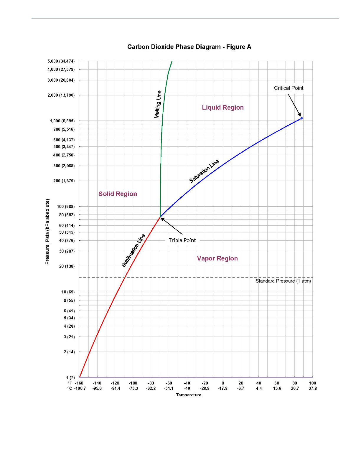
Depending on the temperature and pressure to which it
is subjected, carbon dioxide may exist in the form of a
solid, liquid or gas. At a temperature of 69.9°F (56.6°C)
and a pressure of 60.4 psig (417 kPa), CO2 can exist
simultaneously in all three phases. This condition is known
as the triple point. The phase diagram for CO2 is shown in
Figure A.
Product Manual - Orca™ CO2 Series MicroBulk Delivery System
Safety
7

Safety Product Manual - Orca™ CO2 Series MicroBulk Delivery System
8

Product Manual - Orca™ CO2 Series MicroBulk Delivery System
Introduction
9
Theory of Operation
Although the Orca CO2 Series system can have pressure
or pump delivery options, all units have the same general
functional operating characteristics. They have the ability to
be lled with liquid CO2 and deliver that product to the end
customer safely and eciently.
Terminology of Cryogenics
Cryogenic
A product retaining a temperature of -238°F (-150°C) or
colder. Orca delivery systems maintain gases eciently in a
cryogenic liquid state. Gases can be most eciently stored
as liquids. Gases may be liqueed by compression or cooling
them until they liquefy. In order to be maintained in a liquid
state, each gas must be kept at or below their respective
boiling temperatures.
Though liquid CO2 is very cold, it cannot exist below
-69.9°F. While it is technically not a cryogen, it is to be
handled as such.
Liquid density, temperature, and equilibrium pressure change
with the saturation condition of the liquid. Saturation can
also be described as an energy state. Liquid molecules at a
higher energy state (warmer) take up more space, which is
often referred to as liquid growth.
Equilibrium
In a closed vessel the gas and liquid temperatures are the
same. If there is a temperature dierence between the gas
and liquid (with the tank closed), the gas and liquid will
change their temperatures until they are equal. In stationary
tanks, stratication can take place, creating a temperature
gradient across the liquid and vapor. However, the
temperature at the liquid-vapor interface is the same for both.
Saturation Pressure
Pressure (usually in psig) that is used to describe the current
saturation condition of a liquid and gas within a closed
container.
Cryogenic Temperatures
The Orca CO2 Series delivery systems employ nearcryogenic temperatures to store the product in its liquid
state. CO2 can exist as a liquid down to -69.9°F (60.4 psig
saturation). Below that, CO2 becomes solid. CO2 is typically
transported and stored above -20°F (200 psig saturation).
States of Matter
Matter can exist as a gas, liquid, or a solid. Two phase liquid
is a liquid with gas bubbles or slugs of gas due to lack of
pressure (subcool) to maintain equilibrium. Gas and liquid
can exist at a range of temperatures.
Saturation
Dened as the point at which liquid and vapor coexist at the
same pressure and temperature.
Subcool
Raising the vapor space pressure above the current boiling
pressure of a saturated liquid is called subcool. This
contributes to the Net Positive Suction Head (NPSH) to the
pump. The higher the subcool, the less susceptible the liquid
will be to two-phase ow and pump cavitation.
Two-Phase Liquid
The mix of liquid and gas due to the pressure dropping
below the saturation pressure of the liquid caused by the
lack of proper subcool. This can damage the pump and cause
meter inaccuracy.
Cavitation
Dened as the formation of vapor bubbles in a liquid, it
manifests as partial or full loss of pump prime due to the lack
of proper subcool. The pressure of the liquid owing to the
pump has dropped below the saturation pressure. Audible
changes in the pump often are an indication of partial loss
of prime. The pump will stop pumping during full loss of
prime. Cryogenic pumps will be damaged by cavitation.
Some CO2 pumps can handle small amounts of cavitation,
however, cavitation should always be avoided.

Introduction Product Manual - Orca™ CO2 Series MicroBulk Delivery System
10
Vaporization
Changing liquid into vapor by warming the liquid for the
purpose of subcooling or for gas use. The Orca CO2 Series
delivery system uses a pressure building coil inside of a
propylene glycol/water bath heat exchanger in the cabinet.
Vapor Pressure
Pressure of the vapor space within the tank. Measured by
reading the tank pressure gauge or the Flowcom® Flow
Meter System.
Condensation
The conversion of vapors into liquid by cooling the vapors.
The Orca CO2 Series storage vessel pressure during normal
operation will rise above the saturation pressure of the
liquid. This warmer gas will condense to the colder liquid
pressure during transit. The liquid splashes into the gas space
during normal movement of the truck/trailer. The splashing
condenses the gas and drops the pressure. This is known as
"splash-down."
Depressurization Flash Losses
Dropping the vapor space pressure below the saturation
pressure of the liquid causing the liquid to boil. During
the venting of the tank below the saturation pressure of
the liquid, the liquid temperature will drop, the density
will increase, weight of the liquid will decrease, and the
saturation pressure will drop.
Entrainment
Liquid carried along with venting gas. This can occur during
violent depressurization of a tank and during the top lling
of a tank with the vent valve open. Large product losses will
occur during this event.
Liquid Growth
As liquid warms to higher saturation pressures, the volume
increases. Warm liquid is less dense. Less dense liquid takes
up more volume. Liquid growth is a safety concern if the
liquid is allowed to grow until it lls the storage vessel. This
condition is called liquid full or hydraulically full. During
this condition the pressure rises rapidly, the safeties will
relieve, and the tank will vent liquid.
Condensation and the Perma-Cyl®
MicroBulk Storage System
Pressure Drop
An example of condensation can be seen in the lling theory
of a Perma-Cyl tank. Top lling a Perma-Cyl tank without
venting is possible due to condensing warmer gas into liquid.
Pressure lost due to the ow of liquid. The faster liquid ows
through the piping circuit, the higher the pressure drop.
Stratication
Warm liquid is less dense. In a tall vertical tank this less dense liquid will nd its way to the top of the tank. Colder more
dense liquid will remain at the bottom. The layering of temperature zones from top to bottom is called stratication.

Product Manual - Orca™ CO2 Series MicroBulk Delivery System
Operations
11
Modes of Operation
Orca CO2 — First Use — 11
Fill Orca CO2 from Bulk Tank Pump — 11
Fill Orca CO2 from Onboard Pump — 12
Filling Levels - MC-338 — 13
Current Saturation of Liquid — 13
Pressure Build: Heater — 13
Pressure Build: Operation — 14
Pressure Delivery: Hose Reel — 15
Pump Delivery: Bulk Hose — 16
Receiving Tank Commission: Hose Reel — 19
Receiving Tank Commission: Bulk Hose — 19
Hydraulic Power Supply — 19
Methods to Stop Pump — 20
Primary — 20
Trailer Operation — 21
I. Orca CO2 First Fill
The Orca CO2 Series delivery system is shipped under
pressure with a CO2 atmosphere to keep out moisture. It must
be purged prior to use.
1. Remove hoses from storage tubes, set in place and open
cabinet doors.
2. Open Vapor Vent (V-5) valve and vent tank until empty.
3. Open Pump Inlet/Fill (V-1), Pressure Dispense (V-4), PB
Force Feed (V-16), PB Liquid (V-28) valves.
a. Vapor Balance/PB Isolation (V-13), Inner Vessel
Gauge (V-14), Vapor Phase Isolation (V-31), Liquid
Phase Isolation (V-32) valves should already be open,
they are only closed for service.
4. From delivery tank connect vapor balance hose to Fill
Line (DC-1) connection. Use size adapters as necessary.
5. Open Bottom Fill (V-17) supply tank vapor balance
valve to pressurize to 50 psig. Close supply tank vapor
balance valve.
Note: Cryogenicballvalveshaveaow
direction; the higher pressure must
alwaysbeontheinletsideoftheball
valve.Ifthereissignicantlyhigher
pressure on the outlet side, product WILL
leak past the ball valve.
6. Open Vapor Vent (V-5) and vent tank under 5 psig.
Close Vapor Vent.
7. Open Bottom Fill (V-17) and pressurize to 250 psig.
8. Remove the cap from Vapor Balance (DC-5)
connection. Slowly open Vapor Balance (V-44) valve
and purge for 1-2 minutes. Close Vapor Balance (V-44)
valve and replace cap.
9. Remove the cap from Dispense (DC-2) and Hose Reel
Inlet (DC-3) connections. Connect Hose Reel Inlet
(DC-3) to Dispense (DC-2) connection.
10. Slowly open Dispense (V-41), Delivery Flex Hose
(V-47), Delivery Hose (V-46), and Hose Reel Line
Drain (V-6) valves and purge for 1-2 minutes. Close
Hose Reel Line Drain (V-6) valve and leave Hose Reel
Inlet (DC-3) connected to Dispense (DC-2) connection
for hose reel delivery.
11. Slowly open Vapor Vent (V-5) valve 1-2 turns and let
purge 1-2 minutes. Close Vapor Vent (V-5) valve.
12. Crack open the compression tting on the Inner Vessel
Front of Tank (PI-3) gauge and allow leak for 1-2
minutes. Tighten tting before line frosts. Leak check
compression tting.
13. Crack open the compression ttings on the Inner
Vessel Level Indicator (LI-1) and Inner Vessel Pressure
Indicator (PI-2) manifold gauges and allow leaks for
up to 1 minute. Tighten tting before line frosts. Leak
check compression ttings.
14. Close Pump Inlet/Fill (V-1), Pressure Dispense (V-4),
PB Force Feed (V-16), PB Liquid (V-28) and Bottom
Fill (V-17) valves.
15. Open and close Fill Line Drain (V-9) valve to
depressurize connection.
16. Disconnect supply tank vapor balance hose from Fill
Line (DC-1) connection and connect to Vapor Balance
(DC-5) connection.
17. Follow the rest of the instructions in “II. & III. Fill
Orca CO2”.
Operations Product Manual - Orca™ CO2 Series MicroBulk Delivery System
12
II. Fill Orca CO2 from Bulk Tank Pump
1. Remove hoses from storage tubes, set in place and open
cabinet doors.
2. Connect supply tank vapor balance hose to Vapor
Balance (DC-5) connection and connect ll hose from
supply tank to Fill Line (DC-1) connection.
3. Open supply tank vapor balance and dispense valves.
a. This assumes supply tank is at a lower pressure than
Orca CO2. If Orca CO2 is at a higher pressure, swap
Orca CO2 and supply tank in steps 3 and 4.
4. Open and close Vapor Balance Line Drain (V-45) and
Fill Line Drain (V-9) valve to purge air from hoses.
5. Slowly open Vapor Balance (V-44) valve to equalize
pressure in tanks.
6. Open Bottom Fill (V-17) and Pump Inlet/Fill (V-1)
valve.
7. Start supply tank pump lling and monitor liquid level.
8. When liquid level is getting close to full (3/4 of net
capacity), open Vapor Balance Line Drain (V-45) valve.
a. The vapor balance line serves as the 95% full trycock.
9. When liquid exits the Vapor Balance Line Drain (V-45),
valve stop the pump and close the Bottom Fill (V-17)
valve.
10. Close the Vapor Balance Line Drain (V-45), Pump
Inlet/Fill (V-1), and Vapor Balance (V-44), supply tank
dispense & vapor balance valves.
11. Open and close the Fill Line Drain (V-9) and Vapor
Balance Line Drain (V-45) valves to drain and release
all pressure.
Warning! Fast depressurization of liquid
CO2 can cause dry ice to
form, holding in pressure that
quickly releases when the dry
ice melts. Follow proper safety
procedures for draining and
venting liquid CO2 from hoses.
III. Fill Orca CO2 from Onboard Pump
1. In order to minimize pump cavitation and surging:
a. The liquid level in the supply tank must be above the
Orca CO2 pump inlet height. As such, supply tanks
should be limited to vertical tanks or horizontal tanks
located above the Orca CO2 pump height.
b. Additional subcool in the supply tank will be
benecial.
c. If the Orca CO2 tank pressure is signicantly lower
than the supply tank, causing the supply-tank pressure
to drop below the saturation of the supply liquid when
vapor balancing, pressure in the supply tank must be
added to subcool the liquid.
2. Start truck and engage PTO, turn on cruise control and
increase engage speed to set point.
a. Engine must be at low idle speed to engage PTO.
Caution! Engage the PTO when not at
low idle speed will damage the
PTO.
b. Engine will go to set speed with one push of the
cruise control speed increase button.
Caution! Supply tank must have a
vapor balance circuit for this
functionality otherwise pump
damage may occur.
3. Remove hoses from storage tubes, set in place and open
cabinet doors.
4. From delivery tank connect vapor balance hose to Vapor
Balance (DC-5) connection and connect ll hose from
delivery tank to Fill Line (DC-1) connection.
5. Slowly open supply tank liquid valve to ll pump supply
hose with liquid.
6. Open Fill Line Drain (V-9) valve until CO2 snow comes
out and close valve. This purges air and lls the hose
with liquid.
12. Disconnect hoses from Vapor Balance (DC-5) and Line
(DC-1) connections.
13. Close cabinet doors and stow hoses. Replace all dust
caps.
7. Make sure Pump Inlet/Fill (V-1) valve is closed.
8. — If supply tank is higher pressure than Orca CO2:
a. Open Bottom Fill (V-17) valve.
b. Start pump with Switch (SW-1).
c. When supply tank pressure comes within 5 psig
of Orca CO2 tank pressure, open supply tank

OperationsProduct Manual - Orca™ CO2 Series MicroBulk Delivery System
13
vapor balance and Orca CO2 Vapor Balance
(V-44) valves.
— If Orca CO2 is higher pressure than supply tank:
a. Open supply tank vapor balance and Orca CO2
Vapor Balance (V-44) valves.
b. Open Bottom Fill (V-17) valve.
c. Start pump with Switch (SW-1).
9. Monitor for pump to catch prime.
a. Pump discharge pressure should be 70 psig higher
than tank pressure (bypass valve factory setting).
b. In recirculation mode, if pump discharge pressure
is less than 50 psig higher than Orca CO2 tank, pump
did not catch prime; stop pump and restart or open the
Pressure Dispense (V-4) valve to help catch prime.
10. Open Pressure Dispense (V-4) valve and throttle to
maintain pump discharge minimum 25 psig higher than
Orca CO2 tank pressure.
a. This keeps the pump on the pump curve, maintaining
prime.
b. Too little pressure dierential can cause pump
cavitation.
c. Too much pressure dierential creates a low ow rate.
Close Fill Line Drain (V-9) and Vapor Balance Line
Drain (V-45) valves.
Warning! Fast depressurization of liquid
CO2 can cause dry ice to form,
holding in pressure that is
quickly released when dry ice
melts. Follow proper safety
procedures for draining and
venting liquid CO2 from hoses.
17. Disconnect hoses from Vapor Balance (DC-5) and Line
(DC-1) connections.
18. Close cabinet doors and stow hoses. Replace all dust
caps.
19. Disengage engine speed control and disengage PTO.
Filling Levels - MC-338
The DOT regulations limit the ll levels based on the
tank’s pressure control valve settings. This volume assures
that when the pressure control valve discharges the tank is
not liquid full. This ll volume varies with the saturation
pressure of the liquid. DOT ll levels are based on the
weight of the liquid. Dierential pressure liquid level gauges
are an approximation of the pounds of liquid in the vessel.
The true full liquid level should be determined by the full
trycock. Both are dependent on the vessel being level.
11. Monitor liquid level and pump pressure.
12. When liquid level is getting close to full (3/4 of net
capacity), open Vapor Balance Line Drain (V-45) valve.
a. The vapor balance line serves as the 95% full trycock.
Note: DonotpressurebuildwithOrcaCO
afterllinghasstarted.IfthePBcoil
isoverrun,liquidwillenterthevapor
balance/full trycock line, giving a false
indicationthatOrcaCO2 is full.
13. When liquid exits the Vapor Balance Line Drain (V-45)
valve stop the pump (SW-1) and close the Bottom Fill
(V-17) valve.
14. Close the Pressure Dispense (V-4) valve.
15. Close the Vapor Balance Line Drain (V-45), Vapor
Balance (V-44), supply tank dispense & vapor balance
valves.
16. Open the Fill Line Drain (V-9) and Vapor Balance Line
Drain (V-45) valves to drain and release all pressure.
2
Current Saturation of Liquid
Upon arriving at a delivery site, the Orca tank pressure
indicator (PI-1) will reect the current saturation pressure.
During travel the liquid splashes condensing the warmer
vapor. This is referred to as “splash down.” During pressure
building operations the tank pressure will rise. This is not
an increase in the saturation pressure but an increase in the
subcool. During normal deliveries the saturation pressure
will remain the same as at arrival.
IV. Pressure Build: Heater
Note: Instructionsarespecictothestandard
heater and programmable controller.
Otherheatersandcontrollersmaybe
used, refer to their respective manuals.
1. Review heater and heater controller manuals for
additional operational information.
 Loading...