

Page 1
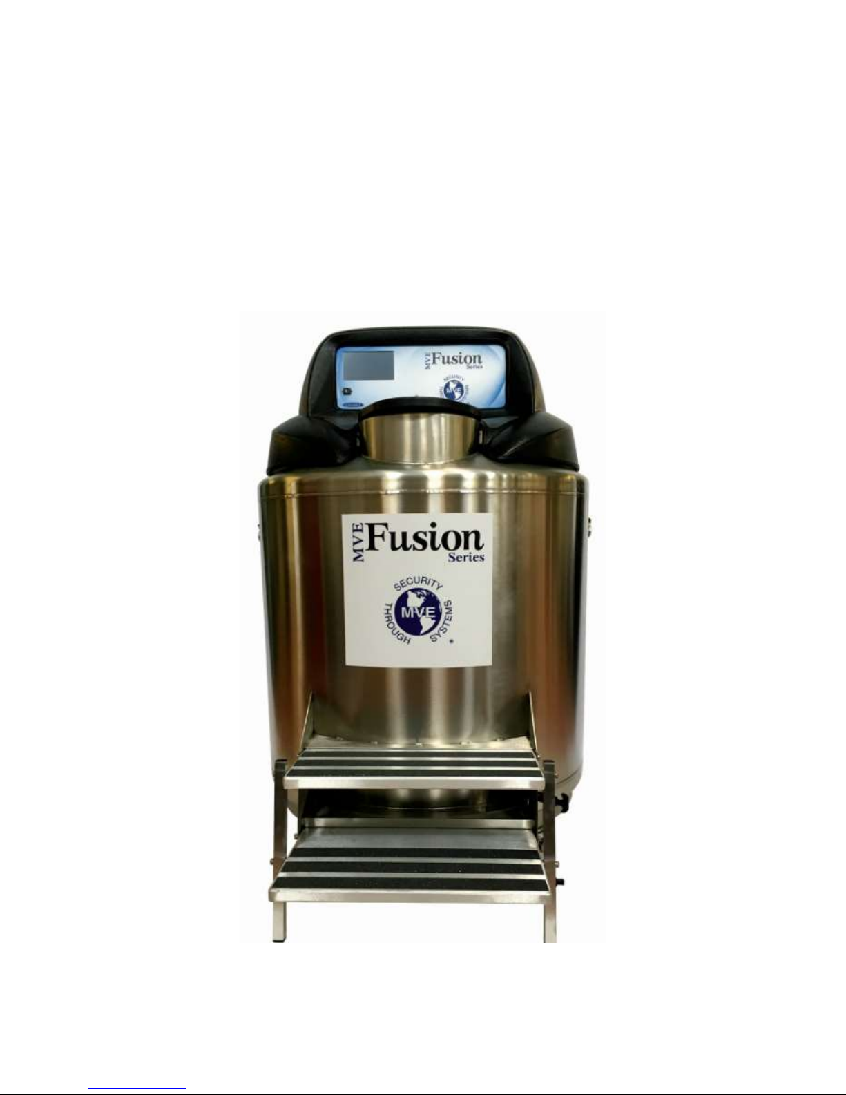
MVE FUSION
Technical Manual
20994124 REV A 1
Page 2

MVE FUSION
Technical Manual
PN 20994124 Rev A
1 Preface
Chart Inc.
2200 Airport Industrial Drive, Suite 500
Ball Ground, GA 30107 USA
Customer / Technical Service:
The Americas Phone: (800) 482-2473 Fax: (888) 932-2473
(770) 721-7759 (770) 721-7758
Asia, Australia, Pacific Rim Phone: +61 (2) 974 94333 Fax: +61 (2) 974 94666
Europe Phone: +44 (0) 1344 403100 Fax: +44 (0) 1344 429224
This manual covers the use and maintenance of MVE Fusion Freezers. READ BEFORE USING THIS EQUIPMENT.
Failure to follow the instructions in this manual can result in damage to the unit, injury to personnel, and/or poor
equipment performance. It is intended for use by trained personnel only. All service and maintenance should be
performed by an authorized MVE Distributor or Service Technician.
NOTE: All MVE Fusion models are Class I per IEC 61140, as the AC electrical supply requires a protective earth
ground. These devices are externally powered and intended for continuous operation. The models are
intended for professional use in research, while the medical device versions are intended to be used in
situations that directly support medical applications. They are not suitable for use with flammable anesthetics.
These devices have been tested to, and are in compliance with UL 61010-1:2012 Ed.3 & CSA
C22.2#61010-1:2012 Ed.3 +G1.
20994124 REV A 2
Page 3
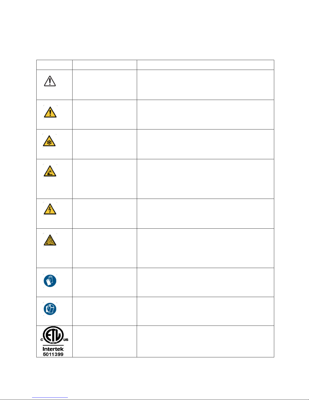
This manual includes the following symbols.
Table 1: the symbols and their descriptions
Symbol Title Description
Caution
Signifies a CAUTION of potentially hazardous
situation when operating the device that may
result in minor to moderate injury or property
damage.
Warning
Warning; Low
Temperature
Warning;
Asphyxiating
Atmosphere
Signifies a WARNING of a potentially hazardous
situation when operating the device that may
result in serious injury or property damage.
Indicates low temperature or freezing conditions.
Take care to avoid exposure to skin, eyes, and
clothing.
Indicates the potential for an oxygen-depleted
atmosphere due to nitrogen vapor. Take care to
operate device in a well-ventilated area.
Warning; Electricity Indicates a potential electrical hazard. Take care
to avoid contact with electricity.
Indicates a potential explosive hazard. The
Warning; Explosive
expansion ratio of liquid nitrogen to gas is 1:700
and can cause explosive conditions if placed into
a sealed container.
Wear Protective
Gloves
Thermal gloves must be worn during indicated
procedures.
Wear a Face Shield A face shield must be worn during indicated
procedures.
ETL Listed Mark Chart Fusion Freezer conforms to UL STD 61010-
1 and certified to CSA STD C22.2#61010-1.
20994124 REV A 3
Page 4
2 Safety
READ BEFORE OPERATING THIS EQUIPMENT
General
Liquid nitrogen (LN2) is used in MVE Fusion Freezers as a refrigerant. Understanding
and following certain safety precautions is extremely important when handling LN2 and
cryogenic containers (commonly referred to as dewars).
Liquid Nitrogen Properties
Nitrogen is a colorless, odorless, tasteless gas. Gaseous nitrogen makes up about 78%
of the Earth’s atmosphere by volume. Once collected, cooled and isolated, nitrogen can
be liquefied.
Boiling Point at 1 atmosphere -195.8°C , -320.3°F , 77.4 K
Thermal Conductivity (Gas) 25.83 mW/(m·K)
Heat of Vaporization (Liquid) 198.38 kJ/kg
Liquid density at 1 atmosphere 1.782 lbs/L , 807.4 g/L , 808.6 kg/m3
Liquid Nitrogen Safety
Transferring LN2 and operating the MVE Fusion should be done in accordance with the
manufacturer/supplier instructions. It is important that all safety precautions
recommended by the manufacturer be followed.
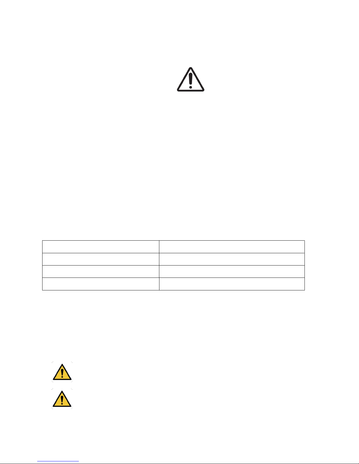
WARNING: Do not modify this equipment without authorization
of the manufacturer.
Nitrogen vapor is a potential asphyxiant as it displaces Oxygen
(O2) in confined spaces. Rapid suffocation can occur without
warning in an Oxygen-deficient atmosphere (less than 19.5%
20994124 REV A 4
Page 5
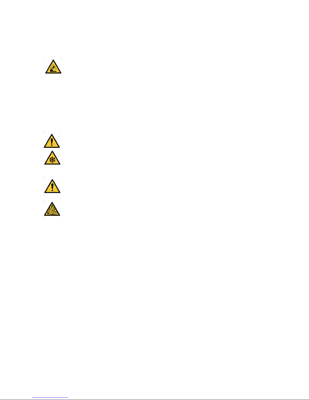
O2). Chart Cryogenic Freezers must be installed and operated
in well-ventilated areas.
DO NOT vent container in confined spaces.
DO NOT enter confined spaces where excess nitrogen gas may
be present.
If exposure has occurred move to ventilated area or fresh air. If
breathing is difficult, supplement oxygen may be required. If
not breathing, give artificial respiration. SEEK IMMEDIATE
MEDICAL ATTENTION.
Contact with liquid nitrogen or uninsulated equipment
containing nitrogen can result in cold contact burns or tissue
damage. Nitrogen vapor can cause damage to skin or eyes.
In case of frostbite, warm area with warm water not exceeding
105°F (40°C) and SEEK IMMEDIATE MEDICAL ATTENTION.
Never place LN2 in a sealed container without a pressure relief
device. The expansion ratio of liquid nitrogen to gaseous
nitrogen is 1 to 700 (1 cubic foot of liquid nitrogen becomes 700
cubic feet of gaseous nitrogen when evaporated).
The two most important safety aspects to consider when handling LN2 are adequate
ventilation and eye and skin protection. Although nitrogen gas is non-toxic, it is dangerous
in that the gas will displace oxygen in a normal breathing atmosphere. Liquid products
are of even greater threat since a small amount of liquid evaporates into a large amount
of gas. Therefore, it is imperative that cryogenic supply and storage dewars be stored
and operated in well-ventilated areas.
20994124 REV A 5
Page 6

Persons transferring LN2 should make every effort to protect the eyes and skin from
accidental contact with liquid or cold vapor. Chart MVE recommends the following
protective clothing and accessories when transferring LN2 or handling hoses, valves, and
plumbing components:
Cryogenic gloves (loose fitting)
Full-face shield or chemical splash goggles
Cryogenic apron
Long sleeve shirt and cuffless pants
Closed toe shoes (no sandals)
Equipment Usage
Cryogenic containers must be operated in accordance with the manufacturer/supplier
instructions. Cryogenic dewars must be kept in a well-ventilated area protected from
weather and away from heat sources. In applications that use a modular liquid cylinder
as a source of LN2, the supply will need to be replenished at regular intervals to ensure
proper operation of the freezer.
Recommended First Aid
Every site that stores and uses LN2 should have an appropriate Material Safety Data
Sheet (MSDS) present. The MSDS may be obtained from the manufacturer/distributor.
The MSDS will specify the symptoms of overexposure and first aid to be used. Here is a
typical summary. If symptoms of asphyxia such as headache, drowsiness, dizziness,
excitation, excess salivation, vomiting, or unconsciousness are observed, remove to fresh
air. If breathing has stopped, give artificial respiration. CALL A PHSYICIAN
IMMEDIATELY.
If breathing is difficult, supplemental oxygen maybe required. If exposure to cryogenic
liquids or cold vapor occurs, restore tissue to normal, body temperature (37°C) as rapidly
as possible, and then protect the injured tissue from further damage and infection.
Rapid warming of the affected areas is best achieved by bathing it in warm water. The
temperature of the water used should not exceed 40°C. Under no circumstances should
the frozen part be rubbed either before or after warming. If the eyes are involved, flush
them thoroughly with warm water for at least 15 minutes. In case of massive exposure,
remove clothing while showering with warm water. The patient should not drink alcohol
or smoke. CALL A PHYSICIAN IMMEDIATELY.
20994124 REV A 6
Page 7
3 System Components and Function
3.1 System Overview
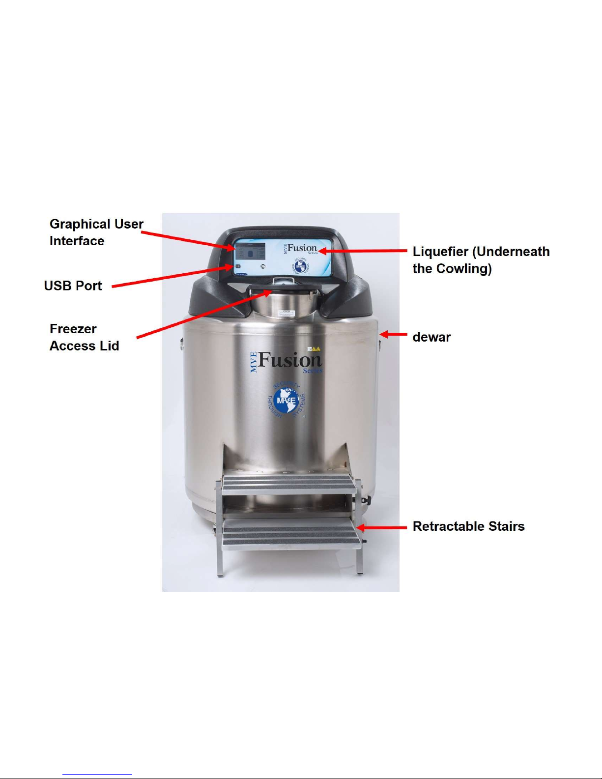
The MVE Fusion system consists of several key components identified in Figures 1 and
2: dewar, Pressure Vessel, Liquefier, Shroud, Graphical User Interface (GUI), and
Retractable Stairs.
Figure 1: MVE FUSION FREEZER
20994124 REV A 7
Page 8
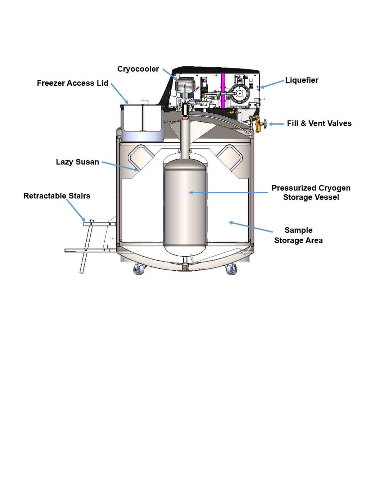
Figure 2: Cross Section of the MVE Fusion Freezer
20994124 REV A 8
Page 9

3.2 Liquefier
The Liquefier contains the cryocooler and other support / interface control systems
required to operate the MVE Fusion Freezer. Replacement of the liquefier should only be
performed by a representative from Chart Inc. or trained authorized personnel.
The Liquefier consists of the following major components and features:
Cryocooler – This is the heart of the system that maintains the liquid nitrogen
stored within the systems pressure vessel. See page 12 for more details pertaining
to the Fusions cryocooler.
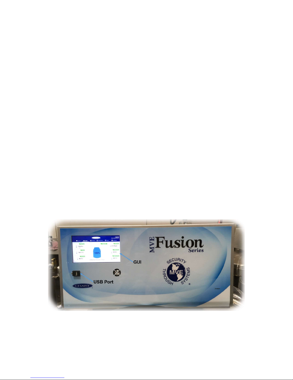
Graphical User Interface (GUI) – This is a touch-screen interface with customized
software intuitively designed for monitoring the MVE Freezer. The 155mm x 87mm
backlit LED display provides system security through password protected
admission. The main screen allows quick access to and displays key parameters
such as the internal freezer temperature, the cryogen liquid level, cryocooler motor
temperatures, the cryogen pressure and system alarms.
Battery Backup – A 12V, 9.0Ah, sealed lead acid battery allows for monitoring of
the freezer parameters and alarms for a minimum of 24 hours after a power loss.
Main Control Board – An advanced printed circuited board (PCB) with control
logic and memory for storage of settings, parameters and historical events.
Variable Frequency Drive (VFD) – The cryocooler is powered by this variable
frequency, variable voltage power supply. Control of the VFD is accomplished by
signals sent from the main PCB based on the freezer status. Voltage to the
cryocooler is modulated to maintain a constant freezer temperature and optimize
power consumption.
20994124 REV A 9
Page 10
Cooling Fans – Two 12 VDC, 150CFM fans with “CPU” style heat exchangers
reject heat from the cryocooler and electrical components within the liquefier to the
ambient environment.
Alarms – In addition to the visual alarms displayed on the GUI, an alarm speaker
is provided that sounds when any preset threshold (freezer temperature, low
battery, motor temperature, VFD temperature, gas pressure, etc.) is exceeded or
if the freezer lid has been removed for more than 5 minutes.
Serial Communication – Two full-duplex RS-232 communication ports are
provided to monitor the VFD and control system and modify parameters. These
are for use by trained service technicians or other qualified personnel only.
USB port – A standard USB interface allows easy access to download the event
historical logs.
Global Alarm Contacts – A normally open and normally closed set of dry contacts
are provided for monitoring alarm conditions.
Figure 3: Front Perspective of Liquefier with the Cowling off
20994124 REV A 10
Page 11
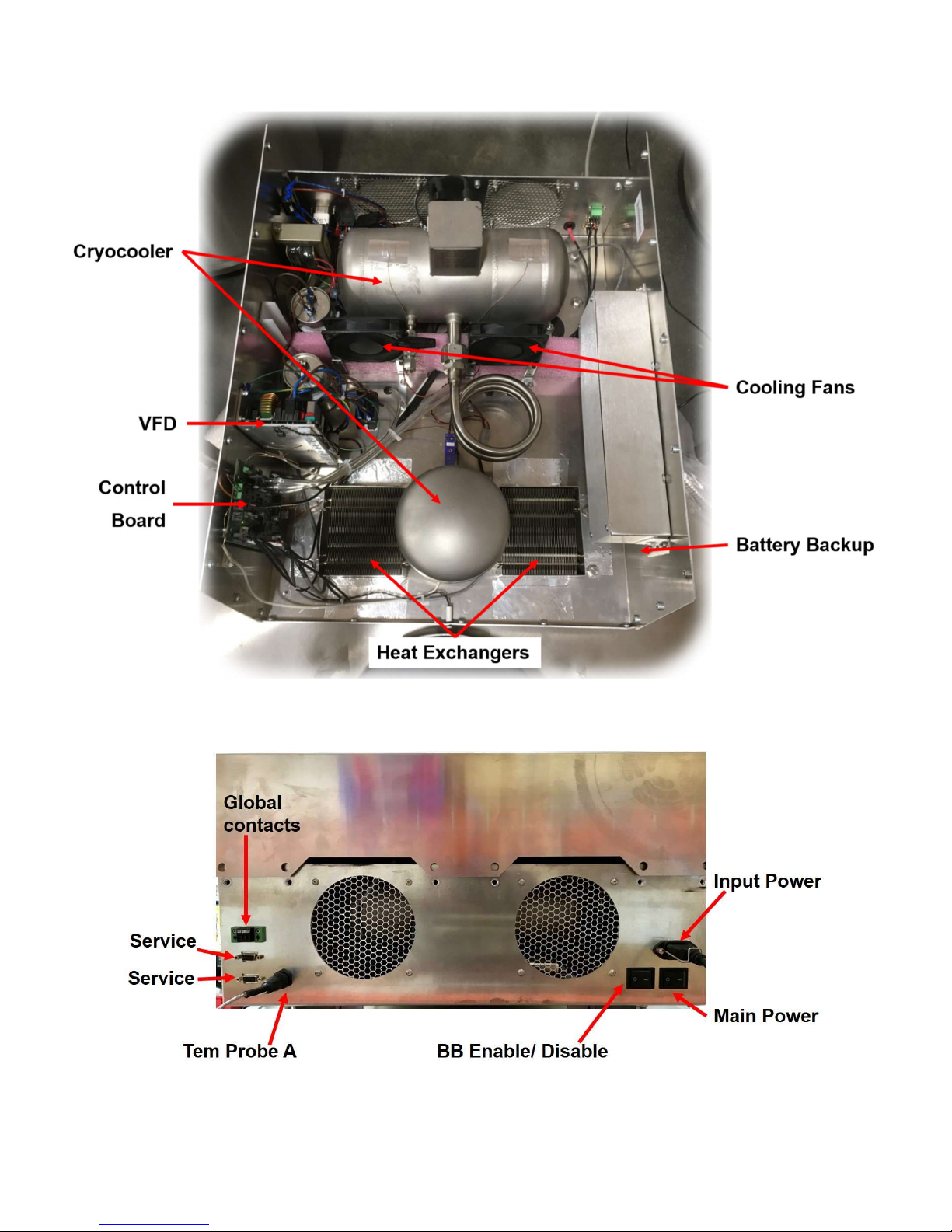
Figure 4: Internal Components of Liquefier
Figure 5 : Liquefier back panel / Physical connections (Cowling off)
20994124 REV A 11
Page 12
3.3 Cryocooler
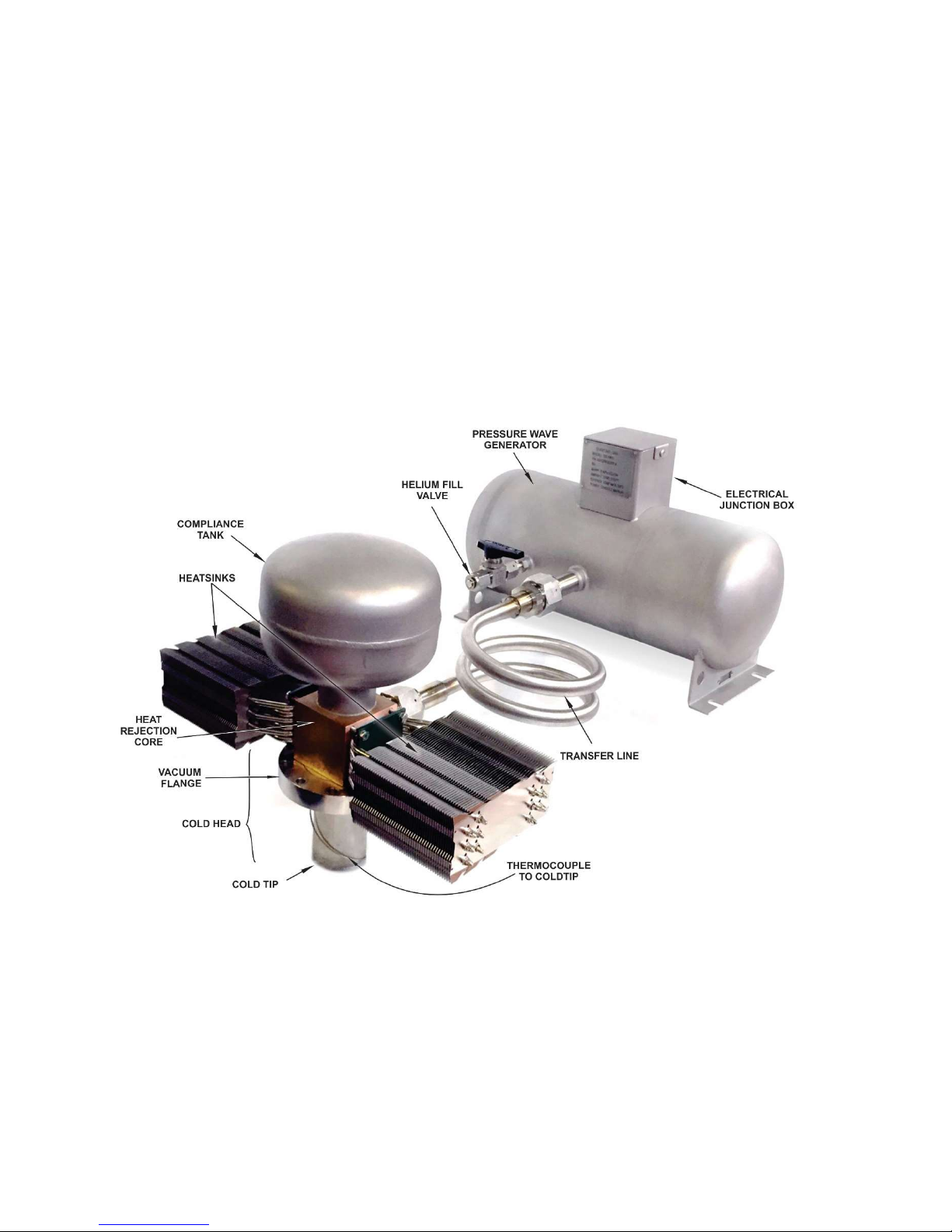
The cryogenic cooler is the refrigeration device for the MVE Fusion. It is mounted on top
of the MVE Fusion dewar. It provides cryogenic cooling by mechanically compressing and
acoustically expanding the helium gas in a Stirling cycle. The base cryocooler unit
consists of a pressure wave generator (PWG) and a coaxial Stirling (pulse tube) coldhead
(see Figure 6). As liquid nitrogen boils off it rises to the top of the pressurized inner LN2
storage tank. There heat is removed from the gaseous nitrogen by the cryocooler and
converted back into a liquid. This highly efficient design eliminates the need for a constant
supply of LN2 and allows for autonomous operation. Figure 6 shows a schematic
representation of the cryocooler.
Figure 6: Cryocooler
20994124 REV A 12
Page 13
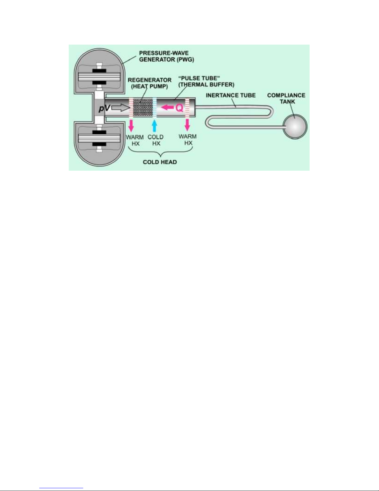
Figure 7: Schematic cross section of Cryocooler
The cryocooler system operates as follows (refer to Figure 7):
1. Helium gas is cyclically compressed and expanded relative to the mean pressure
by the pistons of the PWG.
2. With each forward stroke of the pistons helium gas moves through the first warm
heat exchanger (the “aftercooler”) where heat is removed. Helium is next forced
through the regenerator, which precools the gas before it reaches the cold heat
exchanger (see Error! Reference source not found.).
3. As the gas moves toward the cold heat exchanger, gas in the acoustic network
(thermal buffer tube, warm heat exchanger, and reservoir) also moves in the same
direction. Even as the driven gas stops advancing, when the pistons reach their
upper limits, the helium gas continues moving in the inertance tube, driven by its
own inertia. This acts like a virtual piston, moving away from the cold exchanger,
expanding the cold gas. As the cold gas expands, it gathers heat from the
surroundings (the area or substance to be cooled).
20994124 REV A 13
Page 14

4. The pistons begin withdrawing, and helium then moves back through the
regenerator and aftercooler. Still delayed by its inertia, the gas in the inertance
tube follows, and the cycle begins again.
The heat exchangers and pressure wave generator are cooled by the fans which blow air
over the motor enclosure and main heat rejection core.
3.4 Dewar
Chart is the leading global manufacturer of vacuum insulated biological storage freezers.
Standard Chart MVE freezers use liquid nitrogen as the cooling medium; it boils off as
heat leaks to the outside, which maintains the internal temperature, but requires a
constant replenishing of liquid. This limits installations to areas where LN2 is readily
available and easily transported to each freezer location. The MVE Fusion leverages
Chart’s vast experience and industry leading technology by incorporating these already
proven freezers into a freezer that runs solely on electricity. The only difference is that an
internal cryogen storage pressure vessel is added along with a cryocooler to maintain the
cryogen in a liquid state. The MVE dewar consists of the following major components and
features:
Stainless Steel Construction – All storage and pressure vessel components are
constructed of welded stainless-steel offering decades of service life.
Vacuum Insulation – The annular space around the sample storage compartment
is vacuum insulated to virtually eliminated conduction and convection losses.
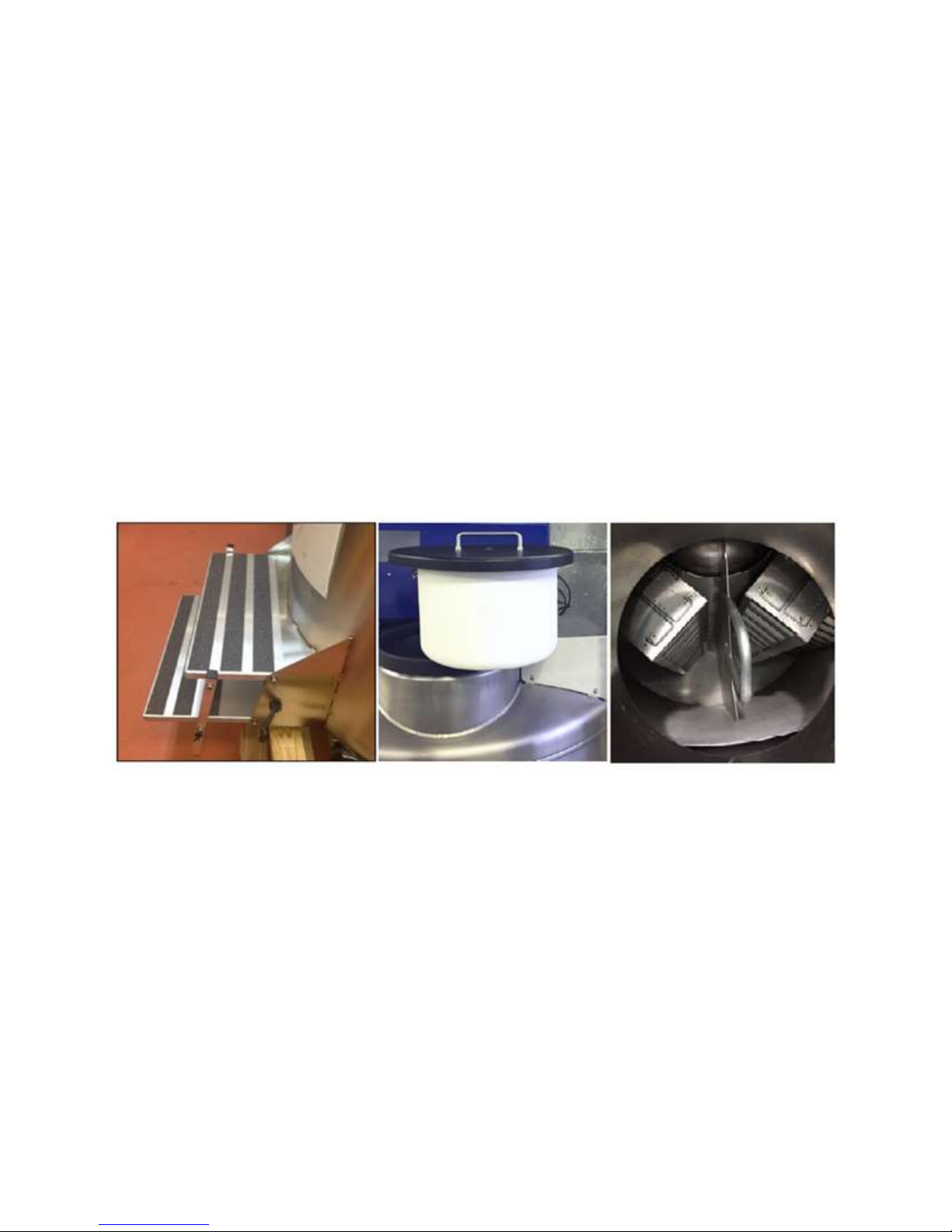
Retractable Stairs – Offer safe, easy access to the freezer storage area.
Access Lid with Cork – Light, easily removable lid with magnetic switch that
indicates when the lid has been removed or improperly placed.
Storage Space – The MVE Fusion is designed with a rotating tray, lazy Susan,
which allows access to all samples without difficulty.
20994124 REV A 14
Page 15
Temperature Monitoring – An RTD is provided to monitor the upper storage
space temperature and control the freezer operation.
Cryogen Storage Pressure Vessel – 50-liter liquid nitrogen storage tank
designed to ASME standards with safety pressure relief device and muffler.
Liquid Level Sensing – Differential pressure sensors continuously monitor the
liquid nitrogen level.
Fill and Vent Ports – Easily accessible valves are provided for initial filling and
venting of liquid nitrogen (see Figure 9).
Figure 8: Retractable Stairs, Removable Lid and lazy Susan within the Storage
Space
20994124 REV A 15
Page 16
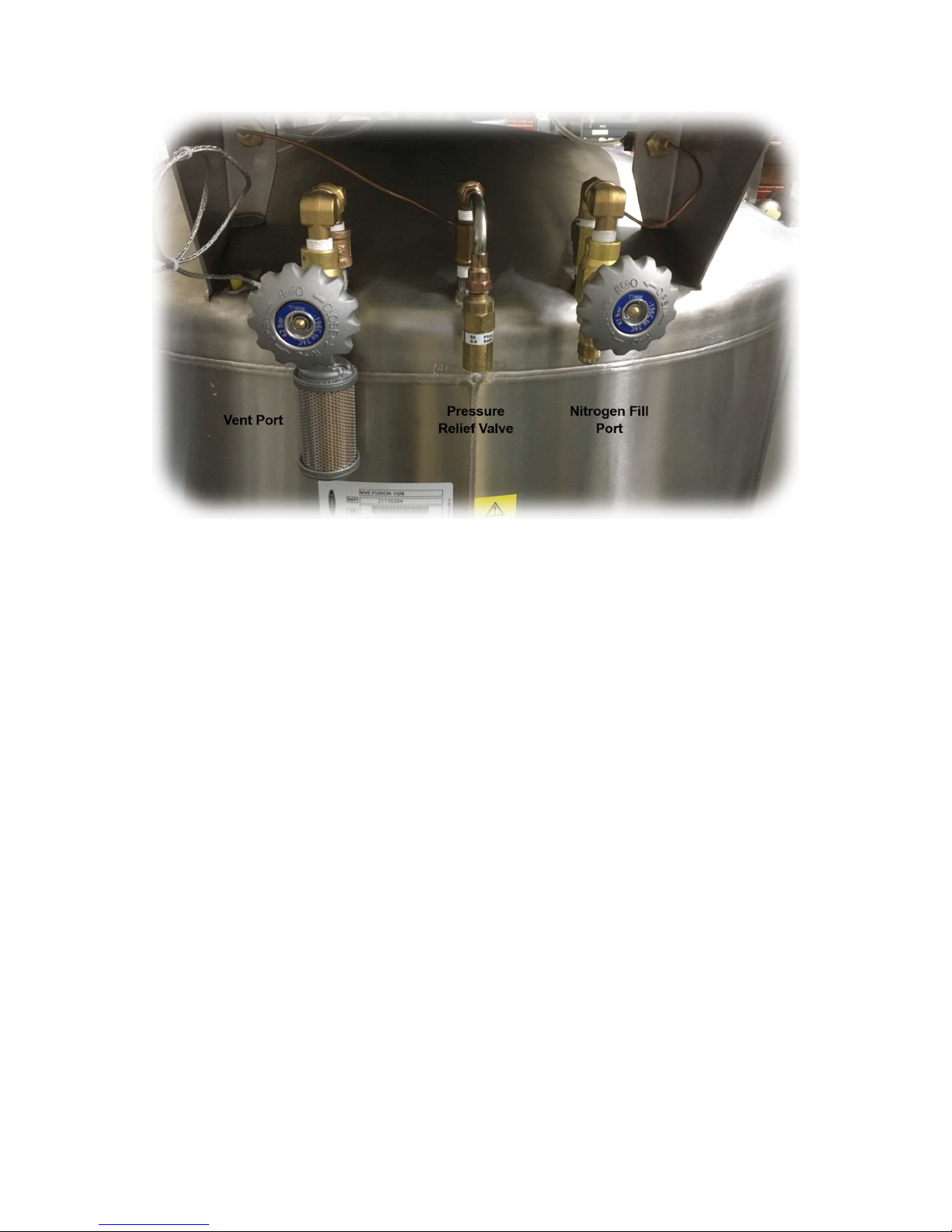
Figure 9: Left to Right: Vent (Overfill) Valve, Relief Valve, and Fill Valve
20994124 REV A 16
Page 17
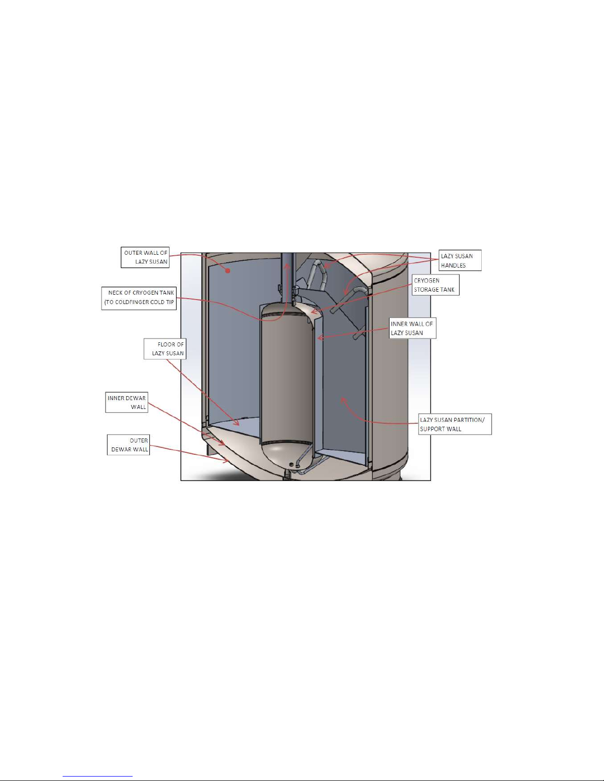
3.5 Pressure Vessel and Sample Storage Area
The dewar is based on the Chart’s MVE High Efficiency Freezers, with modifications to
incorporate a cryogen tank and cryocooler. The “lazy Susan” Carousel for sample racks
is suspended from the neck of the cryogen tank and can be turned easily using the
handles provided. The inner cryogen tank is filled nearly to the top, so that the entire
outside of the tank serves as heat-exchange surface to cool the air inside the storage
space. The initial fill of the cryogen tank is performed when the unit is first delivered to the
customer site (by Chart or an authorized distributor).
Figure 10: Cross-Section View of Cryogen Vessel within Sample Storage Area.
3.6 Ancillary Equipment
20994124 REV A 17
Page 18
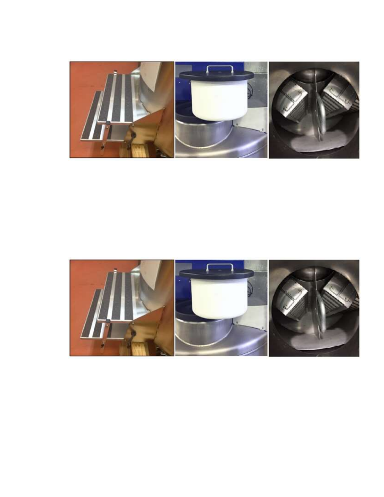
Lid and Cork - The lid covering the storage space (shown in
Figure 8Error! Reference source not found.), the gasket on the rim of the dewar
neck, and the gasket underneath the lip of the lid are all replaceable parts.
Together, they provide insulation and a nearly airtight seal to prevent heat and
moisture from entering the storage space.
Retractable Stairs - The Built-in stairs make it easy to access the storage space.
They can be folded up against the freezer when not in use, as shown in
Figure 8. A restraint is included to keep the stairs from being accidentally unfolded.
Transfer line – In the event the MVE Fusion needs refilling or topping off (for
instance after a prolonged power outage) a proper hose to transfer LN2 from a
supply tank to the pressure vessel is required. See “filling the MVE Fusion” for
more details. A vacuum-jacketed hose with ½” flare fittings on each is required;
Chart recommends using a transfer hose with a “candy cane” pressure-relief
20994124 REV A 18
Page 19
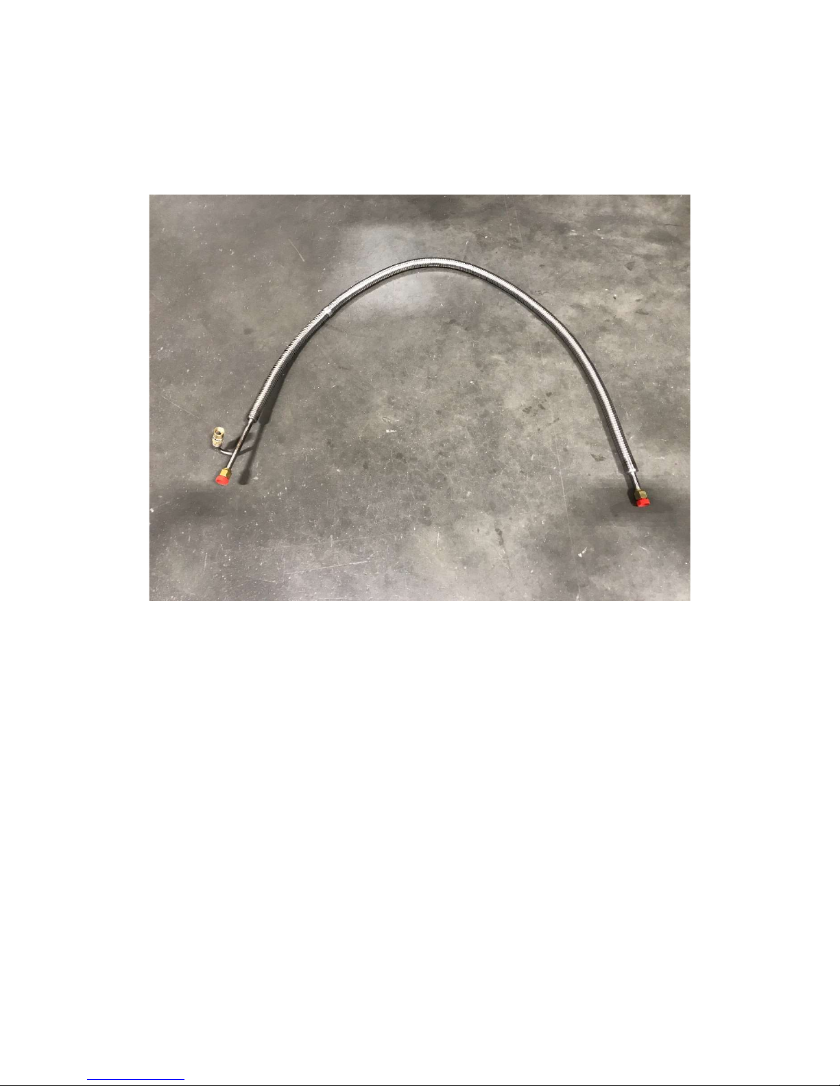
included, to protect against bursting of the hose if the liquid inside should become
superheated. Please see Error! Reference source not found. below for example
of the transfer hose with the candy cane pressure relief valve included.
Figure 11: Transfer hose with the candy cane relief valve included
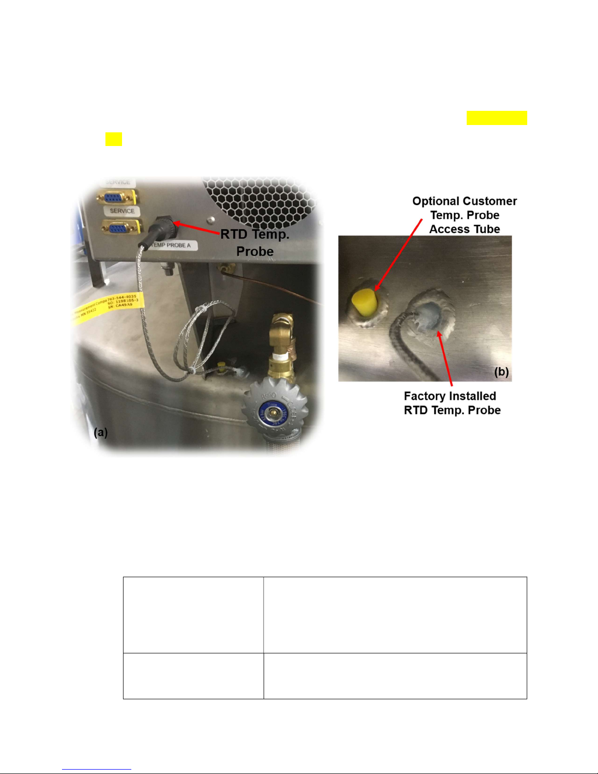
Temperature Probes - The MVE Fusion freezer comes equipped with a factory
installed Resistance Temperature Detector (RTD), with a connection that appears
on the back side of the liquefier enclosure, shown in Figure 12. The RTD probe is
supplied by Chart Industries and is pre-installed, silicone into place and calibrated.
The temperature probe tube communicates directly with the air inside the storage
space to read the air temperature. There is an additional temperature probe tube,
plugged at the factory, that can be used by the customer to install a secondary
probe based on the customer’s requirements. The user’s probe must be small
enough to navigate through a 0.3” ID conduit with a 4 inch-radius bend. If the Chart-
supplied RTD has any issues or requires calibration, please contact Chart
Industries or an authorized distributor. Only certain RTDs are compatible with the
20994124 REV A 19
Page 20
Fusion electronics; in addition to the size requirement, the probe must be a
shielded two-wire (+ and – signal wires, and shield), “PT1000” type, having a
nominal resistance of 1000 ohm at 0 °C. For calibration procedure, see section
7.3.
Figure 12: Fusion temperature probes. (a) Temperature probe on the back panel
of the liquefier, (b) Additional temperature probe access tube for the secondary
temperature probe
3.7 Product Specifications
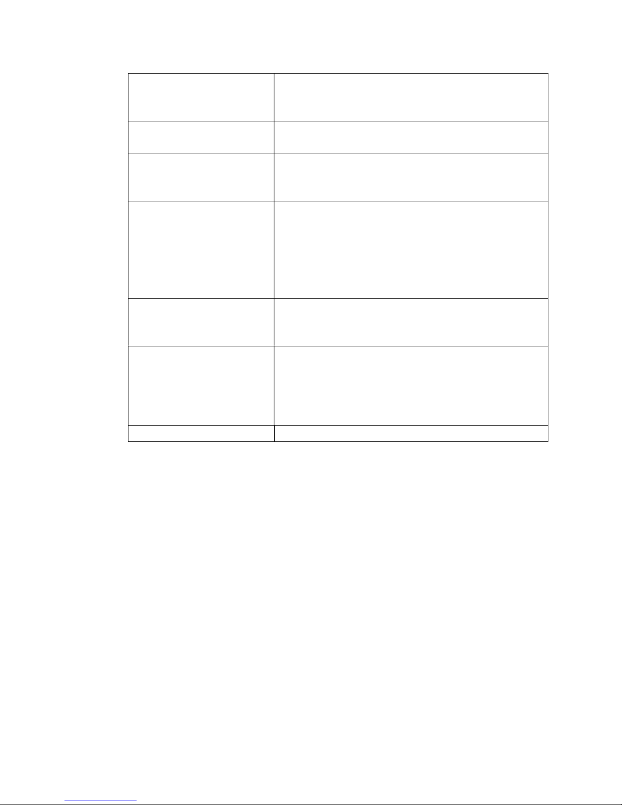
Table 2 : MVE Fusion Product Specifications
Safety for Electrical Equipment
and Lab Use
Physical Dimensions Height: < 65 inches (1625 mm)
ETL marked for use in the United States and Canada
according to:
UL 61010-1:2012 (Edition 3.0)
CSA/CAN 22.2 #61010-1:2012 (Edition 3.0)
ASME Section VIII (Cryogen pressure vessel)
Width: 43.5 inches (1088 mm)
Depth: 57 inches (1450 mm)
20994124 REV A 20
Page 21
Weight (Empty): < 750 lb (340 kg)
Weight (Full): <1100 lb (500 kg) with 20 “13-2 large racks”,
Liftover Height: 37.1 Inches (944mm)
Electrical Power Power Adapter: Class I, 9A @ 120V, 60Hz
Consumption: ~750 W (Maximum)
Operating Conditions
Standard Performance
Pressure Vessel Cryogen: Liquid Nitrogen
Storage Specifications Number of Racks: 20 Standard 13-2 racks (13-shelves for 2”
Controller Operating System Android based GUI
Temperature: 18°C – 27°C (65°F – 80 °F)
Humidity: ≤50% (non-condensing)
Pressure: 8.2 PSI (57.2 kPa) to 14.7 PSI (101 kPa)
Sample temperatures: under -150°C in top box unless:
a) More than two warm 13-2 large racks are added to
the freezer at one time, or
b) Power is lost for more than 5 days with no lid
openings or
c) Lid left open for 15 minutes
Volume: 50 Liters
Pressure Relief Valve: 50 PSI
boxes), plus 16 Mini 13-2 racks.
Number of Vials: 26,000 (standard racks only; 31,000 with
mini-racks)
Vial type: 0.5 to 2mL
20994124 REV A 21
Page 22

4 Installation and Startup
This section will review the basic receiving, installation, and startup procedures for MVE
Fusion freezer. Always inspect the bill of lading for accuracy and external crate/packaging
for damage before accepting the shipment.
Included with each Fusion freezer:
Literature Packet
o Fusion Quick Start Reference Guide – PN 13289481
o Manual Freezer Status Log – PN10936355
o Warranty Statement / Registration / Certificate
6 ft. transfer hose having “candy cane” pressure relief valve (inside freezer)
Liquid Nitrogen handling instructions
Desiccant bag (inside freezer) – To be removed and discarded before use
Silicon tube
A/C electrical power cord
MVE Checklist – Signed by shipping inspector
4.1 Filling the MVE Fusion
Following the careful uncrating and unpacking of the freezer, install using these basic
instructions.
CAUTION: This information is included primarily for reference. Chart recommends any
cryogen filling/refilling be done by Chart personnel or a Chart-authorized distributor.
CAUTION: Always wear protective gloves and face shield when work in with liquid
nitrogen. Refer to the Safety section (3) of this manual.
4.1.1 Procedure for First Fill of the MVE FUSION
Do not power on the Fusion until all steps are followed. Make sure to have two 230 liter
LN2 cylinders at 22-35 PSI for the first fill.
1. Load all racks and empty boxes or alternate inventory systems into the MVE
Fusion, except for those that would cover the access door in the bottom of the
lazy Susan. Refer to Figure 13 for a view inside a Fusion having storage racks
20994124 REV A 22
Page 23
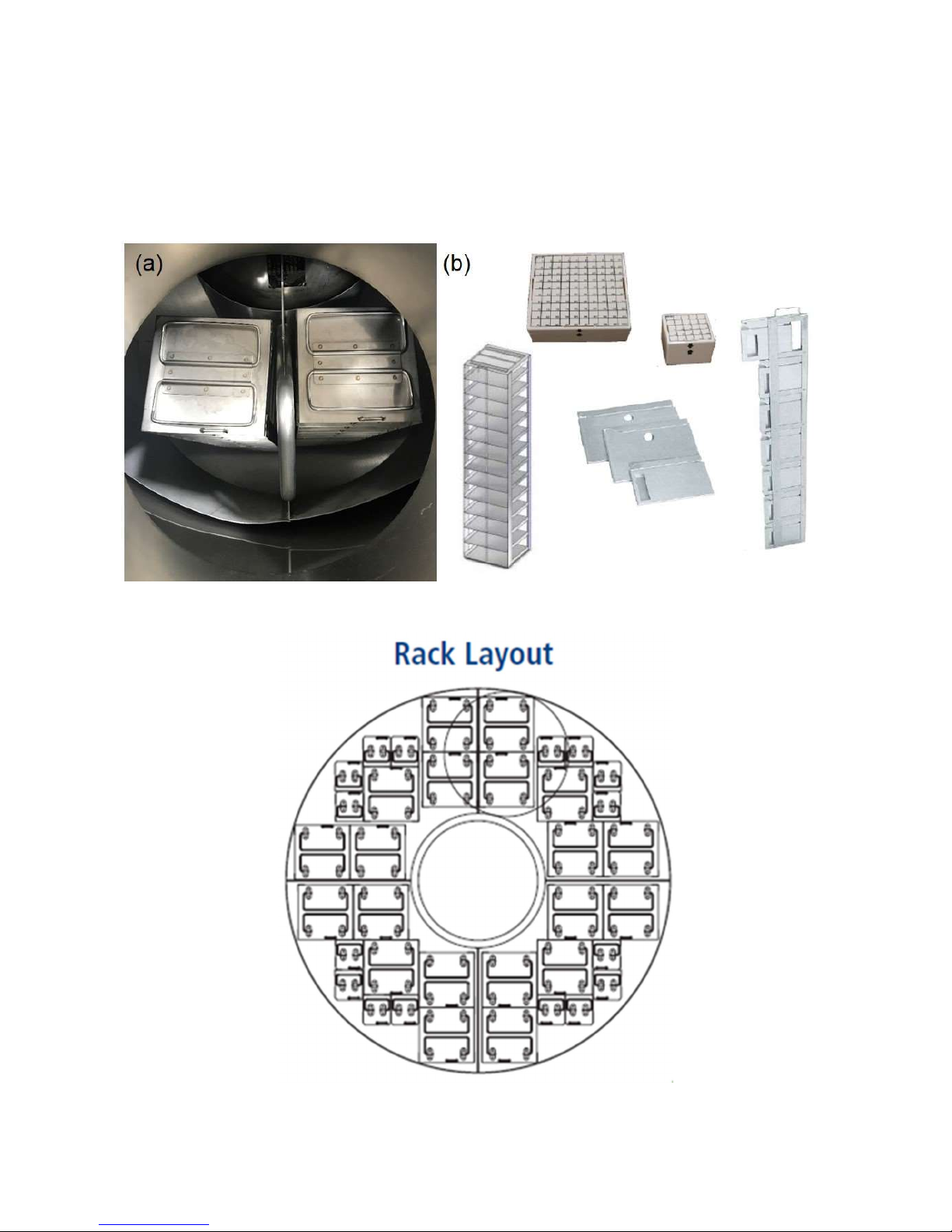
installed and common inventory systems and Error! Reference source not
found. for a standard Fusion rack layout.
NOTE: VERY IMPORTANT TO ADD RACKS AND BOXES BEFORE FILLING.
Figure 13: (a) View inside storage container, (b) Inventory systems
Figure 14: Rack Layout for MVE FUSION
20994124 REV A 23
Page 24
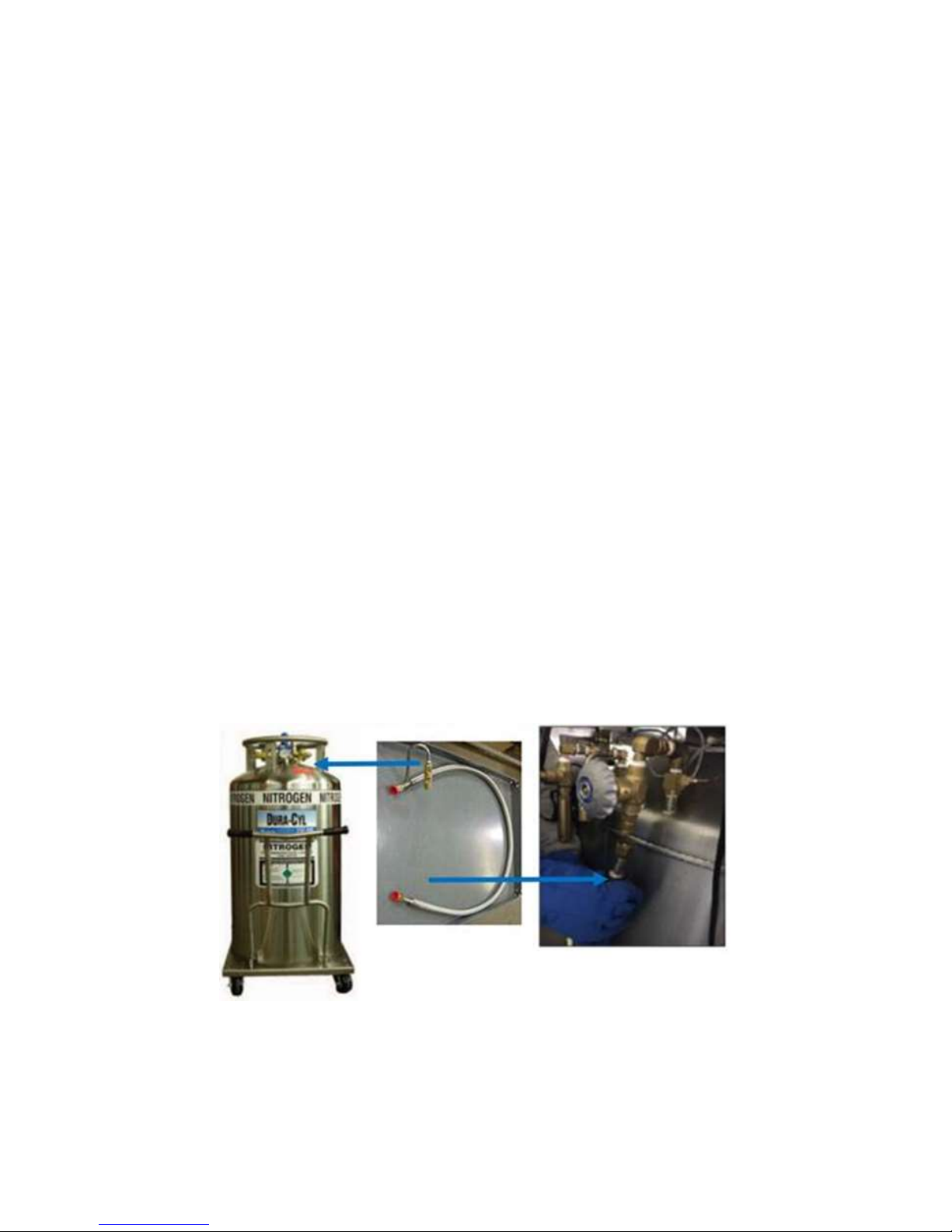
2. Open the access door located in the bottom of the lazy Susan.
3. Connect the supplied transfer hose to the liquid port on the 230 liter LN2 supply
tank using the supplied transfer hose with the “candy cane oriented” in the
vertical position (i.e. the pressufe relif valve (PRV) venting downwards).
4. Insert the other end of the transfer hose into the Fusion dewar storage space.
Chart recommends that a phase separator be placed on this end of the transfer
hose for this filling process.
5. Open the liquid supply valve on the 230 liter LN2 supply tank and fill the bottom
of the storage space with approximately 20-30 liters of LN2 or until the liquid
level reaches the at the bottom of the lazy Susan.
6. Close the liquid supply valve on the 230 liter LN2 supply tank.
7. Remove the phase separator (is used) and connect the available end of the
transfer line to the Fusions inlet port.
Figure 15: Connecting Supply Tank to the MVE FUSION
8. Shut off both isolation valves located underneath the shroud, one on each side
of the liquefier (see Figure 16).
20994124 REV A 24
Page 25
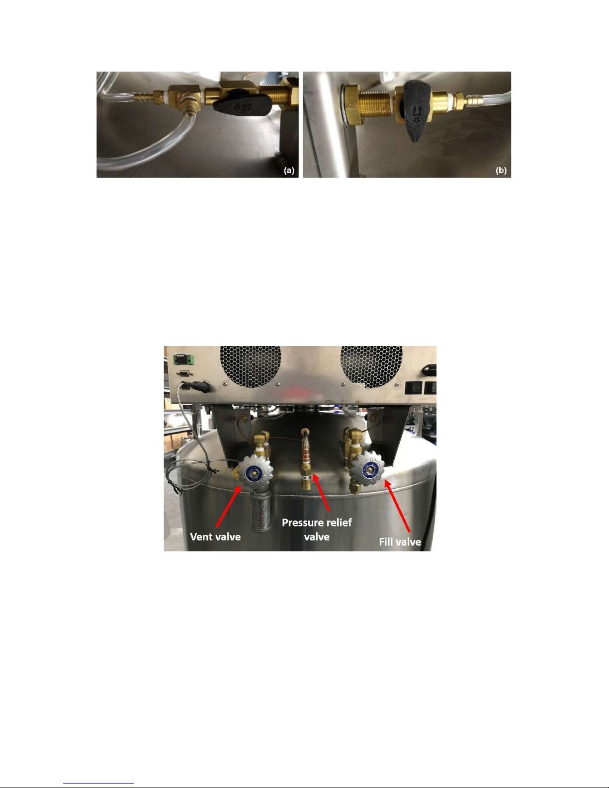
Figure 16: Isolation valve; (a) Open state, (b) Close state
9. Open the liquid supply valve on the 230 liter LN2 supply tank.
10. Open the vent valve on the Fusion (refer to Error! Reference source not
found.). This will prevent over pressurization and lifting the relief valve during
the filling process.
11. Open the fill valve on the Fusion (refer to Error! Reference source not
found.). The vent valve will remain open until the freezer is filled with LN2.
12. Once LN2 begins to flow steadily out of the vent close the vent valve, then close
the fill valve. Immediately thereafter, close the liquid valve on the 230 liter LN2
supply tank.
NOTE: The inner pressure should fill in approximately 30 minutes (using a supply source
of 22-35PSI).
Figure 17: Vent and Fill Valve
20994124 REV A 25
Page 26
13. Open both isolation valves located underneath the shroud (refer to Figure 16).
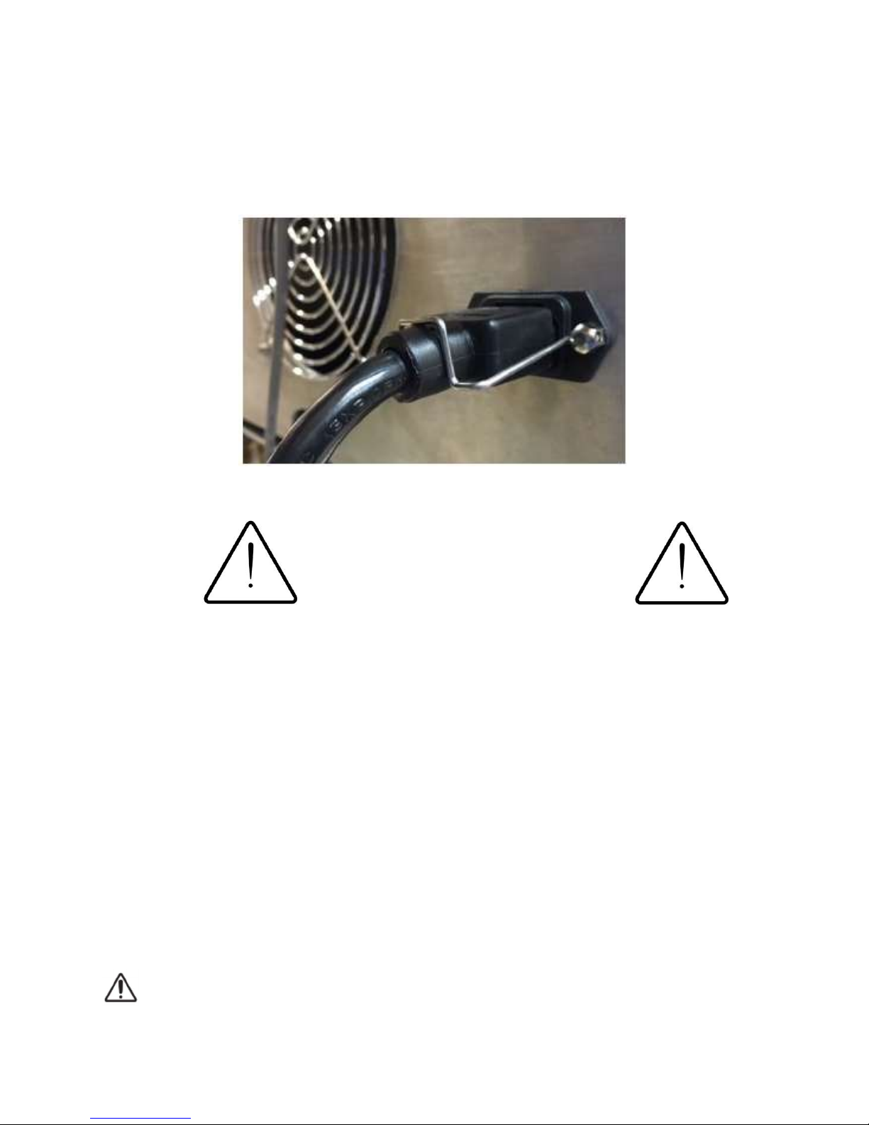
14. Connect the supplied A/C electrical power cord to MVE Fusion power
receptacle at the rear (see for Section 5 further details on system powering).
Figure 18: AC power supply
WARNING
To avoid risk of electrical shock, this
equipment must only be connected to a
properly grounded power source or
outlet.
15. Shortly after filling the pressure vessel, the pressure relief valve will begin
releasing gaseous nitrogen as the storage space and racks within cool down.
This is a result of the liquid boiling off and pressure building above 50 PSIG
inside of the pressure vessel. As the internal chamber and storage racks cool
down to a stable temperature the “relief” events will subside and the pressure
vessel will need to be topped off with LN2. At steady state the operating
pressure within the
CAUTION: Venting will occur which will result in a loss of liquid inside the
pressure vessel if warm racks are installed after the Fusion’s first fill and
if more than 1, 2, or 3 warm racks are installed during its subsequent
20994124 REV A 26
Page 27

operation. Be prepared to have a 230 LN2 cylinder @ 22-35 PSI to refill
pressure vessel if this occurs.
20994124 REV A 27
Page 28
5 Operation
5.1 Basic Operation
The MVE Fusion is a “self-sustaining” cryogenic storage freezer which normally requires
limited user intervention once it has been installed at the customers site and Chart (or an
authorized distributor) performs the first fill. However, there are circumstances (power
outages, for instance) when the system will require attention. There are alarms and other
information provided by the GUI (graphical user interface) to convey important messages
and warnings to the user. Understanding and familiarizing yourself with the Fusion freezer
and the its GUI is recommended for the user for the smooth functioning of the system.
The MVE Fusion uses an Android tablet with a custom-built software application to
monitor the freezers operation.
CAUTION: The user should never operate the Fusion freezer without the
Android running the custom built software application and should never
exit the application during operation.
5.1.1 Starting the Fusion Freezer Safely
This section of the manual will detail the functions and features of the Android application
and demonstrates how to access and monitor the freezer operation.
CAUTION: The Fusion must have LN2 inside the pressure vessel before
electrical power is supplied to it (see Section 4.1.1 for how to fill the
Fusion).
1. Connect the included electric power cord to the back of the unit.
2. Switch the System Power and the Battery Backup power switches (see Figure 19)
to the “On” position (I).
20994124 REV A 28
Page 29
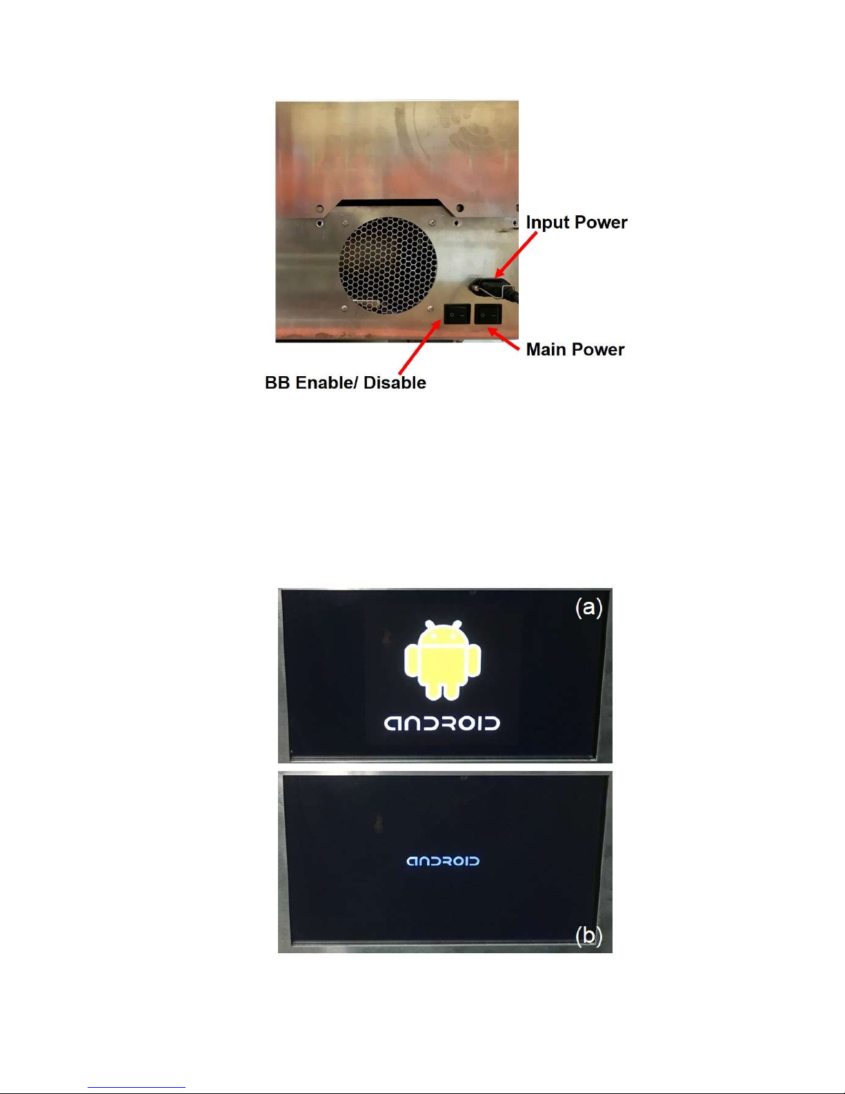
Figure 19 : Main and Battery Backup power switches
3. Once powered on, the MVE Fusion controller will start up with two screens
displaying the Android logos shown in Figure 20 before the main menu of the
Fusion application is loaded.
Figure 20 : Android logo screen that appear when the Fusion system is powered up
20994124 REV A 29
Page 30

5.2 Operating the Android User Interface
5.2.1 Navigating the GUI
There are several screens available within the fusion android application to monitor the
system performance and doing specialized tasks such as resetting alarms or changing
the system password. To reach other screens within the app, swipe sideways with a
finger, or touch the tabs in the upper left-or right-hand corners of the screen the user is
in. For instance, to reach the “Levels” screen from the “Main” screen, touch the “Level”
heading on the upper right-hand corner, or swipe a finger from the right to left (as if
dragging the screen sideways). Then the “Main” screen will be replaced by the Level”
screen.
5.2.2 Main Screen
The main screen displays several key parameters including Freezer temperature,
cryogen level, and temperature distribution (see Figure 21). Some parameters can be
changed from the screen(s); any change takes a minute to become effective, as this is
the sampling interval of the control loop.
20994124 REV A 30
Page 31
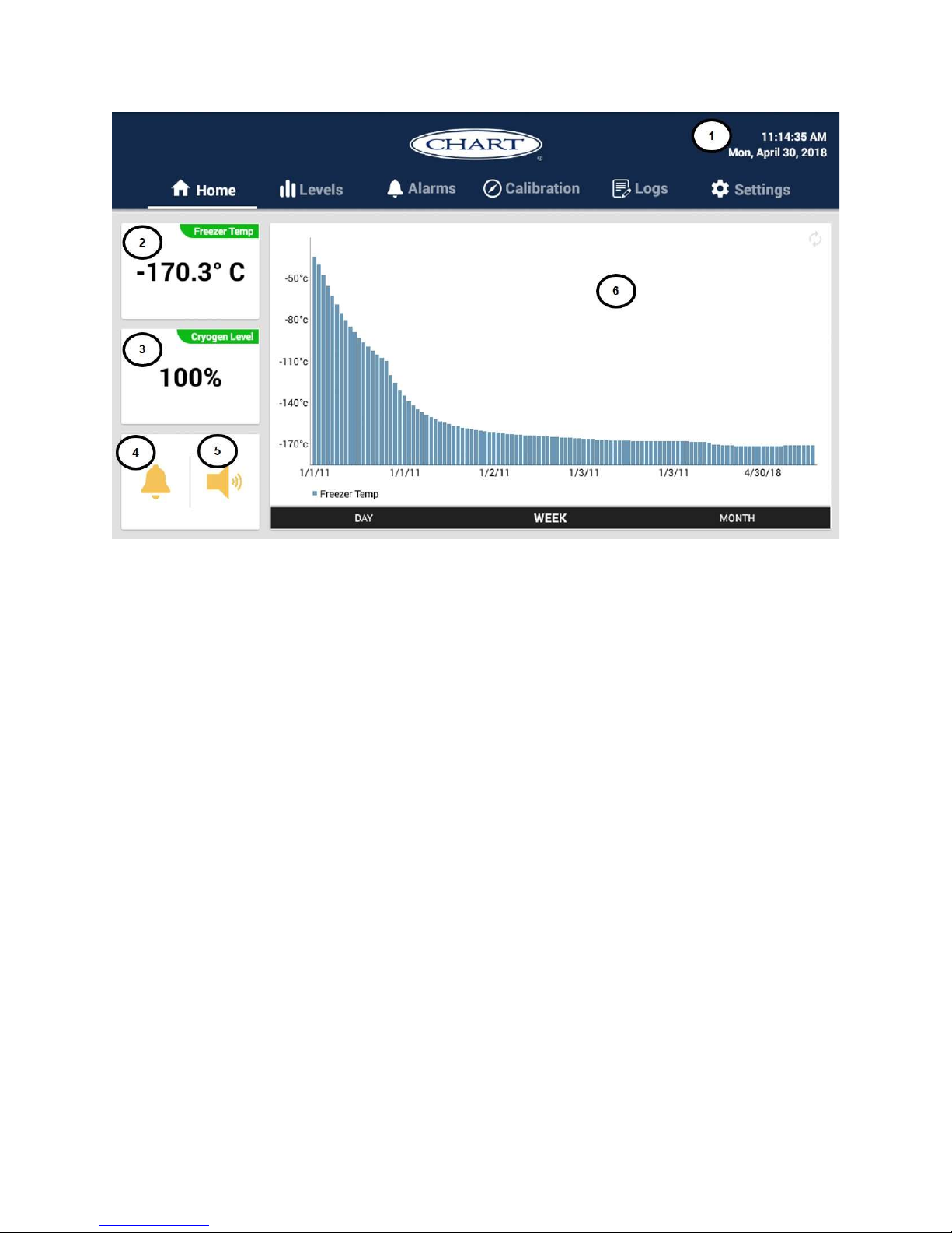
Figure 21: Graphical User Interface Main Screen
1. Current Time and Date – The user can update the Time and date by tapping on
the top right-hand corner.
2. Freezer Temp – Temp A equals the air temperature at or near the “top box” level
of standard storage racks.
3. Cryogen Level - Liquid nitrogen level of the cryogen storage tank (displayed as a
percentage of full level). The level normally does not change, unless there is a
prolonged power outrage and some cryogen is sacrificed to maintain the storage
space temperature. If the cryogen level is below the 50%, user should refill the
cryogen tank and should call for tech service and inform the situation.
4. Alarm Mute Button – This button can be used to mute the alarms. The alarms
can be un-muted by pressing the button again (the system will update after one
minute).
20994124 REV A 31
Page 32
5. Speaker toggle button- This button renders the speaker silent for non-alarm
sounds.
6. Temperature Timeline – This sub window displays the time vs RTD temperature.
It has the capacity to display the data for the selected day or a week or even a
month. In Figure 21, if the user select day option (indicate below the time line), the bar
graph shows the average Freezer temperature recorded for the respective hour.
5.2.3 Level Screen
The level screen displays the amount of cryogen as a percentage available at the given
moment. The same screen provides several other key parameters such as Freezer
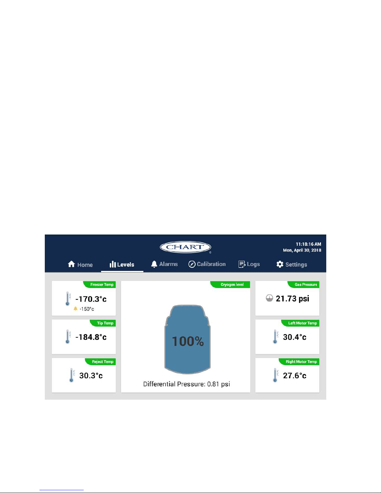
temperature, Cold tip temperature, Gas pressure of the cryogen tank, Left and Right
motor temperatures, and the Reject temperature of the cold tip.
Figure 22: “Level” screen in the GUI.
20994124 REV A 32
Page 33
5.2.4 Calibration Screen
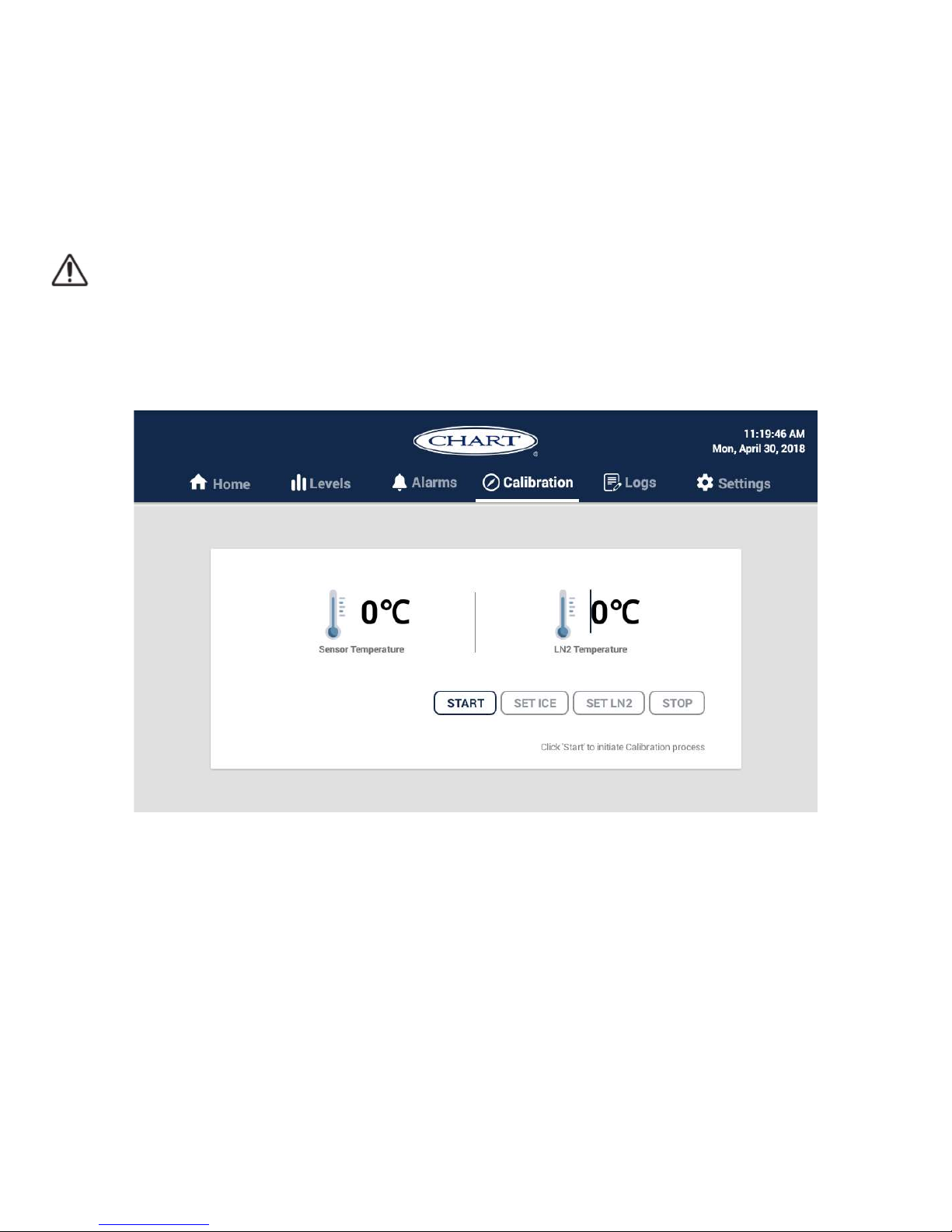
The “Calibration” screen is for calibrating the built in RTD that comes with the MVE Fusion
(see Figure 23). As mentioned earlier, the user does not normally use this feature. This
product has the two-point calibration capability.
CAUTION: This information is included primarily for reference. Chart recommends
the RTD calibration be done by Chart personnel or a Chart-authorized distributor.
The RTD probe must be removed from the freezer in order to be calibrated.
1. Touch the “Start calibration” button.
2. Enter the password in the “Password” field.
3. Select the “Start calibration” button.
4. The default boiling temperature for liquid nitrogen will appear in the “LN2 Temp”
field. This is an altitude-dependent value: enter the appropriate LN2 boiling
temperature for the altitude in which the unit is operating.
Figure 23 : Calibration screen
20994124 REV A 33
Page 34

5. Submerge both probes into LN2 or an ice bath, depending on the type of calibration
being performed. The temperature values displayed are raw data (meaning they
are very sensitive and will change very quickly), so wait for the values to stabilize
before proceeding to the next step.
6. Optional: The calibration step may be cancelled by selecting the “End Calibration”
button now. If cancelled, a message will be displayed indicating that no calibration
was performed.
7. Select the “Set LN2” or “Set Ice” to perform the applicable calibration.
8. Calibrations can be repeated, or a different calibration may be performed, by
repeating steps 4-7 as applicable.
9. When finished, select “End Calibration.” The measured RTD values will go back to
filtered instead of raw data.
5.2.5 Logs Screen
The Log Screen allows the user to save a log file to a thumb drive or other external USB
drives by connecting the storage device to the USB port shown in Figure 1, entering the
password, and pressing the “SAVE FILE” button. The user can select the time frame of
interest (under the “data to save” tab). The log file type is a .csv (comma-separated
values) text file, with the filename in the format FusionLog_yyyy-mm-dd-hh-mm-ss.csv
(the year, month, day, and time the file was written).
The file itself has a header that contains the freezer and cryocooler serial numbers, and
firmware versions of GUI, Fusion, and cryocooler. Data measurements are taken and
recorded hourly and includes the date, freezer temperature, liquid nitrogen level, alarm
code, alarm status code, and status. Most of the data are self-explanatory. But, the alarm
codes are in hexadecimal. Alarm status provide a brief description that user can easily
understand. The software provide capability to download the data per day, week or even
for months.
20994124 REV A 34
Page 35
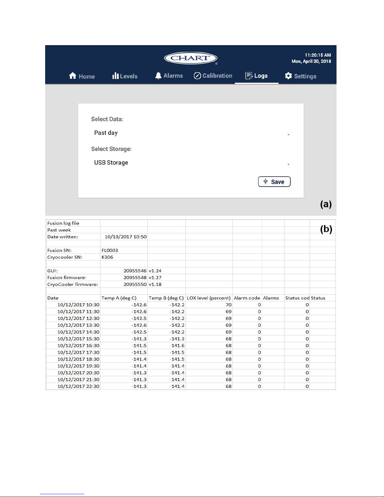
Figure 24 : (a) Format of the Data logs screen, (b) Format of the Data file
20994124 REV A 35
Page 36
5.2.6 Settings Tab
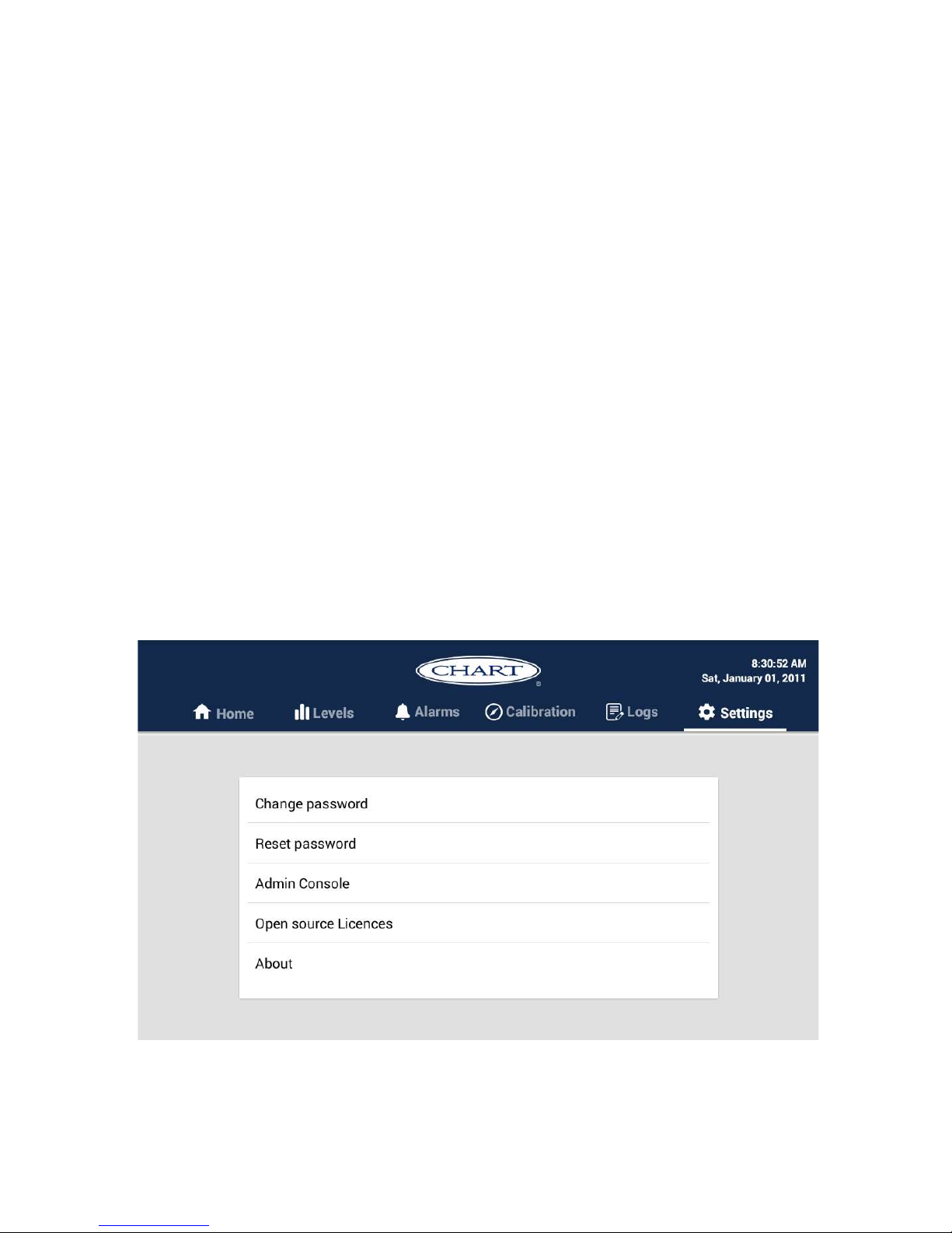
This tab provides the capabilities of changing the password, resetting the password, and
several other options. Password changing process is given below;
1. Select the “Password” screen.
2. Enter the current password in the “Current Password” field.
3. Enter the desired new password in the “New Password” field.
4. Re-enter the new password in the “Verify New Password” field.
5. Click the “Update” button.
6. Wait for a message indicating the password was successfully changed. If the GUI is
unable to change the password, an error message will be displayed.
There is an option to “Reset” the password in case, if user forgot it.
1. Touch the “Reset Password” option (see Figure 25).
2. Then, there will be a pop up window asking “Are you sure” that the user wants to
change the password.
3. If the user select yes, it’ll be revert back to “Default” password of “Fusion01”.
Figure 25: Password screen
20994124 REV A 36
Page 37

The Admin Console provide the opportunity to enter the Fusion and cryocooler serial
numbers along with the Admin password. Next two tabs, open source license details and
serial numbers and GUI versions details will be displayed. The user doesn’t have
capability to change any of these details.
5.3 Routine Operation
Under Normal Operation, the MVE Fusion Freezer operates without any user intervention.
The user has simply to load (Precooled) or remove samples from the storage space as
desired. Nonetheless, there are a few guidelines that will result in the most successful
operation.
Pull the lid up very slowly when removing. This will allow the air inside the
storage space to remain stratified, and maintain high clarity and visibility. Pulling
the lid and cork out quickly will disrupt the inside air and cause warm, relatively
moist air to be drawn in, resulting in fog obscuring the view into the storage space.
Return racks to the freezer as quickly as possible. This maintains the “cold
chain of custody,” ensuring the samples never get warm enough to cause damage.
Reinstall the lid as soon as possible. The Gaskets on the lid and the neck
opening are designed to maintain a nearly airtight seal as long as the lid is left in
place. This prevents moisture from entering the dewar and building up ice and frost
on the surfaces.
No more than 2 warm racks can be added to the freezer at a time. Adding more
than two racks at a time may cause nitrogen pressure to exceed the allowed limit
and vent from the tank. (Be prepared to fill with a 22-35 PSI (1.5 - 2.4 bar) liquid
nitrogen cylinder if this happens). See section 5.1 for details of the filling operation.
To maximize the storage capacity of the freezer, the racks need to be arranged in
an optimum fashion. Figure 24 shows the ideal arrangement of standard racks.
Mini racks may be inserted in some of the remaining unoccupied spaces.
20994124 REV A 37
Page 38

required)
and Moisture Removal
Replacement
5.4 Shutdown MVE Fusion
Switch off the Main Power and Battery backup to shut down the MVE Fusion unit.
Remove the input power cable to isolate from the wall outlet.
There is no system shutdown option in firmware.
5.5 Preventative Maintenance
5.5.1 Preventative Maintenance Schedule
This section describes the preventative maintenance that should be performed on the
MVE Fusion to ensure optimum operation and performance, as well maximum service
life. As with any technical piece of laboratory equipment, preventative maintenance is key
to equipment success.
Table 3: Preventative Maintenance Schedule
Weekly 6 Months 24 Months 60 Months
Level verification X
Thaw Lid/Lid Inspection X
Folding Step Inspection X
Gasket Replacement X
Top off the Inner Vessel
with LN2 (only if
X
Fan Cleaning X
Pressure Relief Valve
Replacement
Complete Freezer Thaw
Backup Battery
X
X
X
20994124 REV A 38
Page 39

Table 4 : Preventative Maintenance Procedures
Item
Action Procedure
No
Level
1
1. Liquid Level can only be verified via the GUI.
Verification
Lid Inspection
2
1. Remove the lid slowly from the MVE Fusion.
2. Inspect lid for any damage and replace parts if necessary
1. Remove the lid slowly from freezer.
2. It is recommended that the freezer opening be covered
with a spare lid or in another non-airtight manner to
prevent moisture from entering the storage space and to
3
4
Lid Thaw
Procedure
Folding Step
Inspection
minimize the top box temperature change while the lid is
open.
3. Allow lid to sit at room temperature for approximately 30
minutes. (Caution-the lid open alarm will sound, press
alarm mute to temporarily silence the alarm)
4. Once thawed, thoroughly dry lid, cork, and liner.
5. Inspect lid for damage and replace parts if necessary.
1. Verify that hinges and free of cracks and all connections
are secure.
2. Check that the anti-slip strips on the steps are in good
condition and replace if necessary (PN 4810179).
3. Ensure the step locking strap is able to securely hold the
steps in their folded position. If the pivot bolts
continuously loosen, apply thread locker (PN 11087674)
and retighten.
20994124 REV A 39
Page 40
1. Depending on the condition of the current gasket, the
gasket, the gasket material can be removed and
replaced or more material can simply be added to the
5
6
Gasket
Replacement
Refill Pressure
Vessel
existing gasket.
2. The replacement gasket material will be a neoprene tape
3. Simply clean the surfaces, remove the tape back to
expose the adhesive and install gasket material.
4. Trim to size as needed.
1. Please refer to Section 5.1 Filling the MVE Fusion on
how to fill the inner vessel of the MVE Fusion.
Chart Authorized person should only carried out this
activity.
1. Make sure the power supply and the battery backup are
7
Fan Cleaning
disconnected.
2. Remove crowling (see Figure 1) and the shroud from
the Liquefier, by removing the four bolts that fasten the
shroud to the top of the freezer.
3. Remove top cover off the Liquefier, by unscrewing the
28 screws that hold the top cover of the liquefier in
place. Use a screw driver.
20994124 REV A 40
Page 41
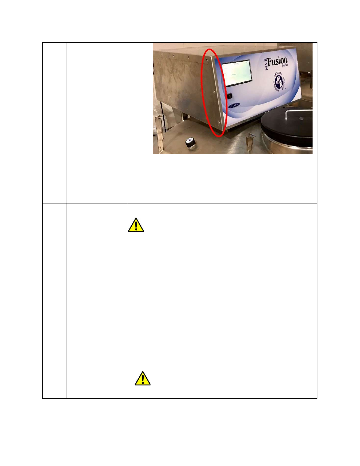
Figure 26: After removing the Screws on the liquefier
4. Take a cloth and wipe away any dust or debris off the
two fans.
CAUTION: Ensure that the LN2 supply valve is
closed and the plumbing assembly is vented before
removing the relief valve.
1. If equipped with a relief valve deflector, loosen the
deflector clamp and slide off the deflector.
Relief Valve
8
Replacement
2. Loosen the relief valve and remove it from the plumbing
assembly. Be sure to support the attachment tube with
wrench to prevent damage from twisting.
3. Install new relief valve (PN 1810032) applying new
Teflon tape if needed. Ensure relief valve is rated to 50
PSI (3.4 bar).
CAUTION: Installing a relief valve with a different
pressure rating could prevent proper operation and
20994124 REV A 41
Page 42

9
Complete
Freezer Thaw
and Moisture
Removal
lead to a dangerous over pressurized condition.
Additionally, this will void any warranty.
1. Unplug the main power and battery backup if equipped.
2. Open or remove lid from freezer.
3. Open the vent valve Allow LN2 to completely evaporate
and the freezer space to warm to room temperature.
Placing a fan blowing into the freezer will accelerate this
process.
4. After it has reached ambient temperature, thoroughly
remove any moisture from the freezer space.
ENSURE ALL MOISTURE IS COMPLETELY
REMOVED PRIOR TO REFILL LIQUID NITROGEN
AGAIN.
10
Battery Backup
Internal Battery
Replacement
General
The GUI will start to lose functionality when the Battery
Backup is NOT capable of generating the required VDC.
To test any suspect BB, disconnect the AC power and
allow freezer to run for 30 minutes; the power failure (PF)
alarm should trigger. While it is still in PF alarm allow the
freezer to perform a fill still using the BB, and once it has
reached its high level set point measure the BB voltage.
If the voltage measures 12 to 13 VDC the batteries are
good. In any case, the best approach is to always
replace a suspect battery or if the battery age is more
than five years old.
Note: New batteries may need to be charged for several
hours before it is able to power the GUI. The GUI will
20994124 REV A 42
Page 43

constantly monitor, charge, and sense the current in its
battery circuit. With its main power connected, the GUI
will constantly produce a 27 VDC trickle charge to keep
the batteries fully charged.
INTERNAL BATTERY REPLACEMENT PROCEDURE
1. Make sure the power supply and the battery backup are
disconnected.
2. Remove Cowling (see Figure 1) from the Liquefier, by
removing the four screws that fasten the shroud to the
top of the freezer.
3. Remove top cover off the Liquefier, unscrewing the
screws that hold the top cover of the liquefier in place
(see Figure 26).
4. Remove the foam insert that sits over the fan and battery
backup.
5. Remove the four Phillips screws holding the backing
plate (Figure 27).
6. Replace the new Battery Backup (PN 21183303).
20994124 REV A 43
Page 44
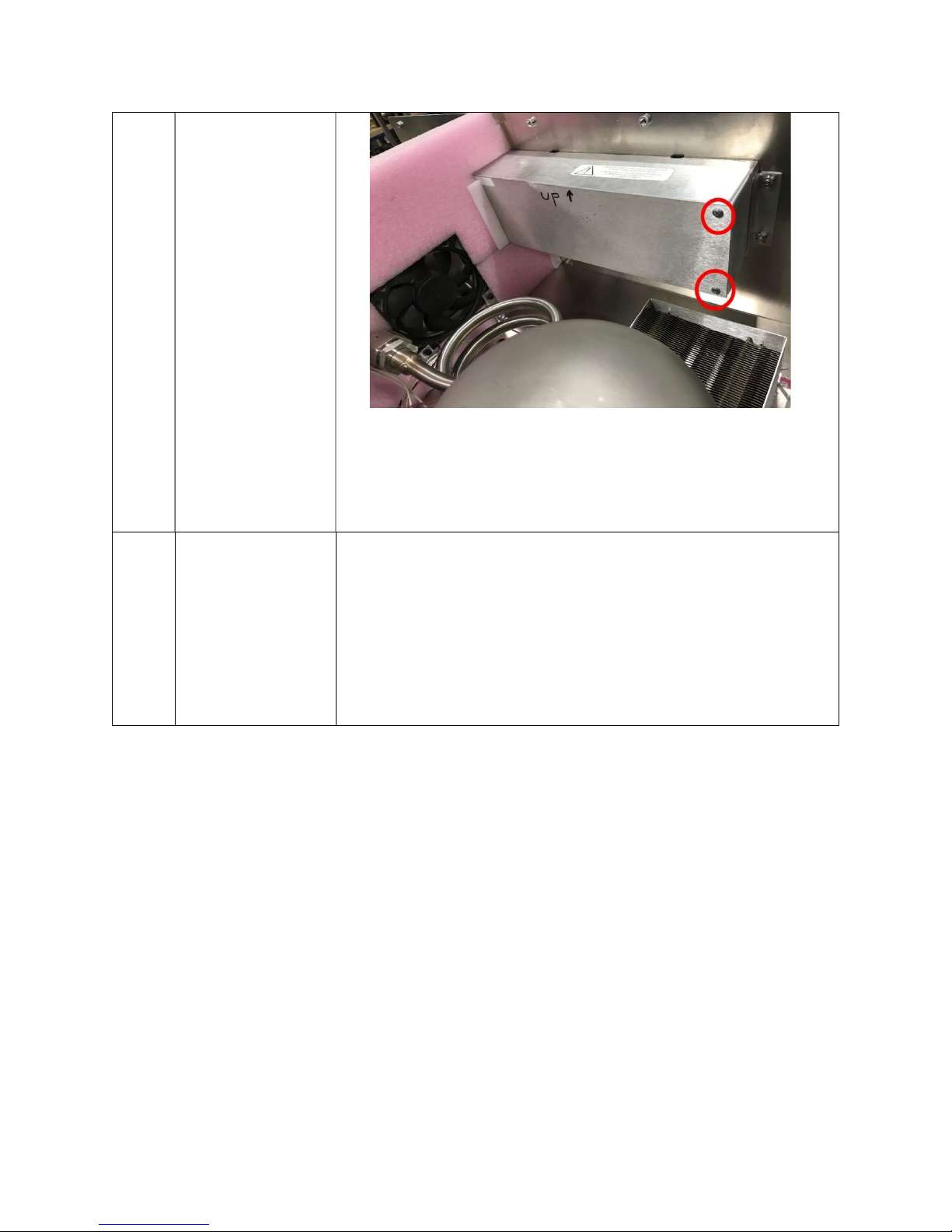
Figure 27: Battery Backup
MVE Fusion firmware should only be updated by authorized
Firmware
11
Updates
Chart personal or MVE Distributors. Improper firmware
updates can render the controller inoperable. Please
contact Chart Technical Service for further details.
20994124 REV A 44
Page 45

5.6 Replacement Part List
M02
Table 5: Replacement Part List
Part Number Descriptions
2S132K-30274 Liquefier
21183303 Battery Backup
1810032
11499812
20570663 Temperature Probe
21183724 Lid Assembly
14010103 Power Cord
21183330 On/Off Switch
21183303 Battery Backup Assembly
Relief Valve – 50 PSI (3.4 bar)
MUFFLER 1/4"MPT WITAN
5.7 End of Life Disposal
The Fusion freezer should be returned to Chart at the end of its useful life for proper
disposal. Please contact a Chart to discuss arrangements.
20994124 REV A 45
Page 46
6 Alarms and Troubleshooting
6.1 Service Ports and Global Alarm Relay
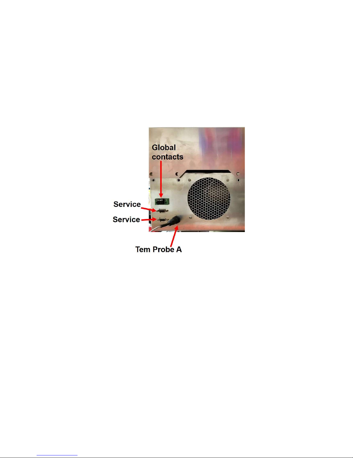
For advance troubleshooting, the Fusion has additional ports on the back panel that allow
an authorized service technician to connect a computer to the control board and log
detailed real time data and error codes.
Figure 28: Advance troubleshooting ports on the back panel
The data streams on the RS232 ports can be accessed by a command-line terminal
application such as TeraTerm. Please contact Chart or an authorized representative to
connect to these ports (passwords are required to access the data or make changes to
parameters).
6.2 Description of Alarms
The following table describes all alarms that available in the Fusion. The codes in
parentheses (in the right-hand column) are the identifiers for each variable in the serial
data one may obtain from the RS232 ports on the back panel. These alarms are only for
information. There is an audible alarm buzzer available in Fusion and that can be
disabled. This will not disable the alarms, only the audible buzzer. Alarms will still be
displayed visually on the screen if the alarm buzzer is inactive.
20994124 REV A 46
Page 47
Table 6: Alarm parameter ranges
Alarm
value b
ut limited to
-
160
°C
Temperature
Parameter
Set Points
Define by
LOW HIGH
Freezer Temperature
No limit
Tip Temperature Alarm No limit
Reject Temperature No limit
Left Motor Temperature
Right Motor
No limit
No limit
-150 °C
-170 °C
50 °C
50 °C
50 °C
User can adjust HIGH
System
System
System
System
Cryogen Level (%) 35 100 System
Liquid Pressure (PSIG) 15 45 System
List of all potential alarm displays, and brief descriptions
Alarm Description Action
NO AC POWER AC power loss
Operating on backup battery. Find alternative
power source.
DATA LOGGING
OFF
LID OPEN Lid is open Replace or reposition lid.
TIP TEMP FAULT Tip temp. open Contact service technician.
SYSTEM
SHUTDOWN
REJECT TEMP
FAULT
MOTOR TEMP L
FAULT
MOTOR TEMP R
FAULT
FREEZER RTD
OPEN
Data logging is off Contact service technician.
Cryocooler Shutdown Contact service technician.
Reject temp. open Contact service technician.
L motor temp. open Contact service technician.
R motor temp. open Contact service technician.
RTD open Contact service technician.
20994124 REV A 47
Page 48

MOTOR R OUT OF
RANGE
Right motor out of
range
Consult technical manual or contact service
technician.
TIP TEMP OUT OF
RANGE
REJECT T OUT OF
RANGE
MOTOR L OUT OF
RANGE
FREEZER RTD
OUT OF RANGE
FREEZER TEMP
SHORT?
VIBRATION FAULT* Vibration fault Contact service technician.
LID OPEN Lid is open Replace or reposition lid.
BATTERY LOW
Tip temp. out of
range
Reject temp. out of
range
Left motor out of
range
RTD out of range
RTD wiring shorted Contact service technician.
Backup battery
voltage is low
Consult technical manual or contact service
technician.
Consult technical manual or contact service
technician.
Consult technical manual or contact service
technician.
Consult technical manual or contact service
technician.
Consult technical manual or contact service
technician.
CRYOGEN OUT OF
RANGE
GAS PRES OUT OF
RANGE
VFD HARDWARE
FAULT
VFD OVER
TEMPERATURE
Cryogen level out of
range
Gas pressure high
Electronics fault Contact service technician.
Electronics over
temp.
Consult technical manual to replenish cryogen
supply.
Consult technical manual or contact service
technician.
Contact service technician.
*The “VIBRATION FAULT” is the one fault not displayed in the GUI but will result in a
system shutdown that can only be cleared by a service technician.
20994124 REV A 48
Page 49
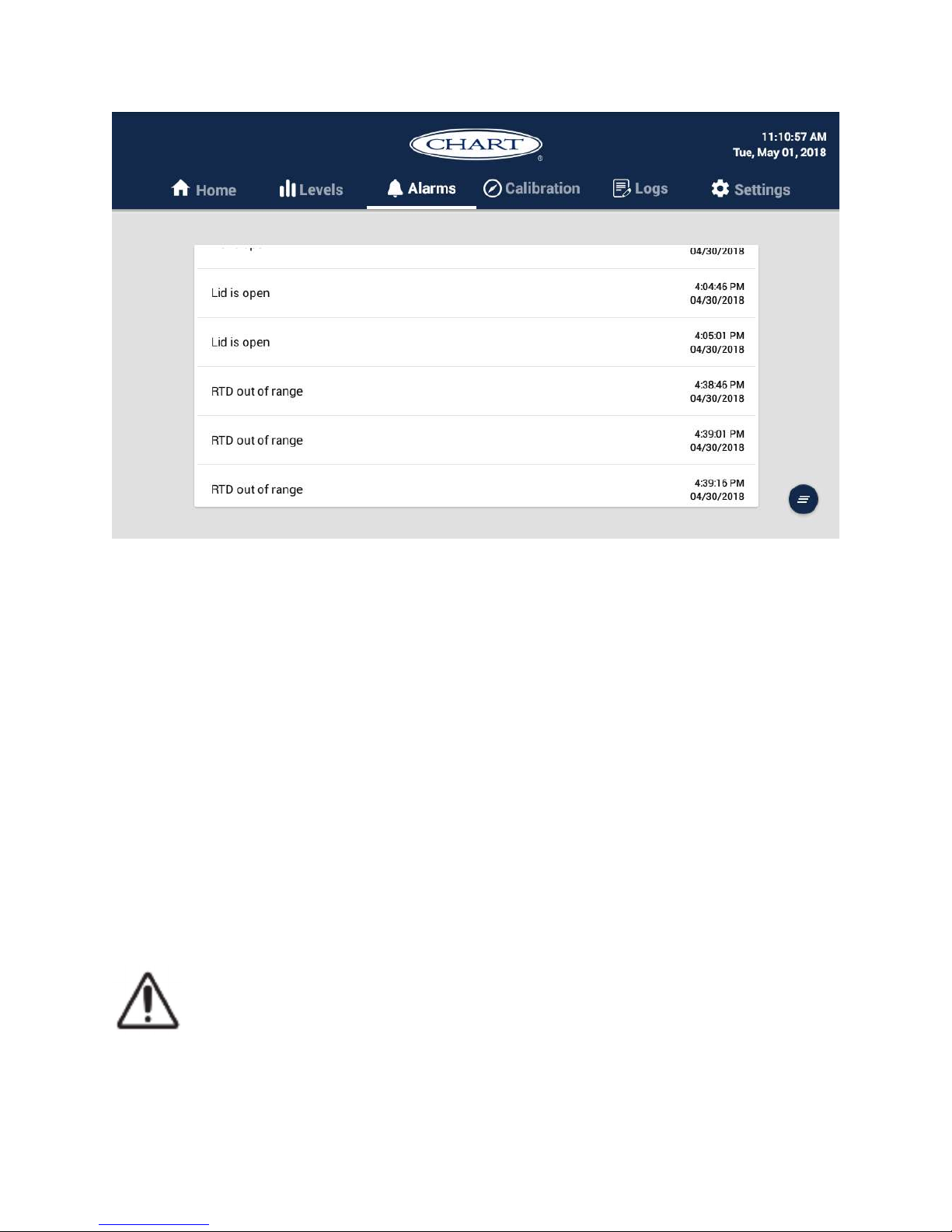
Figure 29: Sequentially recorded Alarm
6.3 Clearing the Alarm Messages
There are several ways to inform an alarm to the user. First, an auditable sound starts
along with a dialog box popup message in the middle of the screen when a parameter is
out of it default range. The same time, same message is stored under the alarm tab for
user to observe them later (Figure 29). Buzzer will stop after 30 seconds. The popup
message can be cleared by pressing the “close” button appeared on the right hand corner
of the message. To clear all the messages in the “Alarms” tab, hit once on the icon given
in the bottom- right corner of the window.
6.4 Troubleshooting
CAUTION: This information is included primarily for reference. Chart
recommends any advance troubleshooting or RTD calibration be done by Chart
personnel or a Chart-authorized distributor.
20994124 REV A 49
Page 50

NOTES:
20994124 REV A 50
Page 51
Chart Inc. reserves the right to discontinue its products, or change the prices, materials, equipment, quality, descriptions, specifications and/or processes
to its products at any time without prior notice and with no further obligation or consequence. All rights not expressly stated herein are reserved by us,
as applicable. Copyright © 2017 Chart Industries
20994124 Rev A
20994124 REV A 51
 Loading...