

CHART MVE 1536P-190, MVE 815P-190, MVE 1879P-150, MVE 1539P-190, MVE 1879P-190 Operating And Maintenance Manual
...
Chart Cryogenic Freezers
with MVE TEC3000 Controllers
Operating and Maintenance Manual

MVE Biological Systems
TEC 3000 Operating and Maintenance Freezer Manual
13289499 Rev G • 2
Chart Cryogenic Freezer
MVE TEC 3000 Controller
Operating and Maintenance
Manual
P/N 13289499 Rev H
Preface
Chart Inc.
2200 Airport Industrial Drive, Suite 500
Ball Ground, GA 30107
USA
Chart Inc.
BioMedical Group
Customer / Technical Service:
Americas Phone: (800) 482-2473
(770) 721-7759
Email: techservice.usa@chart-ind.com
Asia, Australia, Pacific Rim Phone: +61 (2) 974 94333
Europe Phone: +44 (0) 1344 403100
Read this manual. Failure to follow the instructions in this manual can result in damage to the unit, injury
to personnel, and/or poor equipment performance. This manual covers the use and maintenance of MVE Cryogenic
Freezers and the TEC 3000 control system. It is intended for use by qualified personnel only. All service and
maintenance should be performed by an authorized MVE Distributor.

MVE Biological Systems
TEC 3000 Operating and Maintenance Freezer Manual
13289499 Rev G • 2
2. Table of Contents
1.
Preface ......................................................................................................................................... 4
2.
Table of Contents .................................................................................................................... 2-4
3.
Safety and First Aid ................................................................................................................ 5-6
4.
Certifications and Listings ...................................................................................................... 7
5.
Product Information ................................................................................................................. 8
5.1.
MVE Freezer Models ................................................................................................... 8
5.1.1.
MVE High Efficiency / Vapor Series ....................................................... 9
5.1.2.
MVE Series ............................................................................................. 10
5.1.3.
MVE Stock Series .................................................................................. 11
5.1.4.
MVE Cabinet Series ............................................................................... 12
5.1.5.
MVE HEco Series ................................................................................... 13
5.1.6.
MVE CryoSystem 6000 Full Auto Series ............................................. 14
5.2.
Plumbing Assembly ............................................................................................ 15-19
5.3.
TEC 3000 Display ...................................................................................................... 20
5.4.
TEC 3000 Stand Alone Back Panel / Physical Connections ................................. 21
5.4.1.
TEC3000 HEco/Cabinet Back Panel / Physical Connections .......................... 21-22
5.4.2.
TEC3000 12-Pin Wiring Harness Details ................................................................ 23
5.5.
Specifications ............................................................................................................ 24
5.6.
Operating Environment ............................................................................................ 25
6.
Installation and Startup ................................................................................................... 26-29
7.
Operation ................................................................................................................................. 30
7.1.
Functions and Features ............................................................................................ 31
7.1.1.
Liquid Nitrogen Level Measurement.................................................... 32
7.1.2.
Automatic Liquid Nitrogen Level Control ........................................... 33
7.1.3.
Liquid Nitrogen Usage .......................................................................... 34
7.1.4.
Temperature Measurement ................................................................... 35
7.1.5.
User Defined Alarms ....................................................................... 36-37
7.1.6.
Remote Alarm Monitoring ..................................................................... 38
7.1.7.
Passwords / Security............................................................................. 39
7.1.8.
Communication / Networking Capabilities ......................................... 40
7.1.9.
Event Log And Event Codes ...................................................... 41-42
7.1.10.
Lid Switch ................................................................................................ 43
7.1.11.
Hot Gas Bypass ...................................................................................... 44
7.1.12.
Battery Backup (Optional) ..................................................................... 45
7.2.
Adjusting Settings and Options .............................................................................. 46
7.2.1.
Temperature Settings ............................................................................ 47
7.2.1.1.
Enable / Disable Sensors .................................................. 47
7.2.1.2.
High Temperature Alarm Test .......................................... 48
7.2.1.3.
Temperature Alarm Settings ....................................... 49-50
7.2.1.4.
Liquid Nitrogen Saturation Temperature......................... 51
7.2.2.
Liquid Level Settings ............................................................................. 52
7.2.2.1.
Level Setpoints and Alarms .............................................. 52
7.2.2.2.
Enable / Disable Auto Fill Control .................................... 53
7.2.2.3.
Level Offset ......................................................................... 54
7.2.3.
Additional Feature Settings .................................................................. 55
7.2.3.1.
Battery Backup Status ....................................................... 57
7.2.3.2.
Hot Gas Bypass Settings ............................................ 56-57
7.2.3.2.1.
Stuck Valve Alarms ........................................................ 57
7.2.3.3. Lid Switch Settings ............................................................ 58
7.2.4.
Display and Output Settings ................................................................ 59
7.2.4.1.
Temp and Level Display Units .......................................... 59
7.2.4.2.
Liquid Usage Display ......................................................... 60
7.2.4.3.
Alarm Buzzer ...................................................................... 61
7.2.4.4.
Languages .......................................................................... 62
7.2.4.5.
Printer .................................................................................. 63

MVE Biological Systems
TEC 3000 Operating and Maintenance Freezer Manual
13289499 Rev G • 3
7.2.5.
Advanced Settings ................................................................................ 64
7.2.5.1.
Timed Filling .................................................................. 64-65
7.2.5.2.
Maximum Fill Time ............................................................. 66
7.2.5.3.
Time and Date ............................................................... 67-68
7.2.5.3.1.
Communication Settings................................................ 69
7.2.5.3.2.
COM Setup / Type .......................................................... 69
7.2.5.3.3.
MODBUS ID .................................................................... 70
7.2.5.4.
One Fill All Fill (OFAF) ....................................................... 71
7.2.5.5.
Restore Default Settings ............................................. 72-73
GLOBAL PASSWORD ........................................................................................................... 73
7.2.5.6.
Restart Controller............................................................... 74
7.2.5.7.
Firmware Update .......................................................... 75-76
7.2.6.
Password / Security Setup ................................................................... 77
7.2.6.1.
Password Entry Mode ....................................................... 77
7.2.6.2.
Global Password Change .................................................. 78
7.2.6.3.
Multilevel Passwords ......................................................... 79
7.3.
Calibration Procedures ............................................................................................. 80
7.3.1.
Temperature Sensor Calibration .......................................................... 80
7.3.1.1.
Single Point Calibration .................................................... 81
7.3.1.2.
Two Point Calibration .................................................. 82-83
7.3.2.
Liquid Nitrogen Level Calibration .................................................. 84-87
7.3.3.
Hot Gas Bypass Sensor Calibration and Removal ...................... 88-89
7.3.3.1.
Hot Gas Single Point Calibration ..................................... 90
7.3.3.2.
Hot Gas Two Point Calibration ......................................... 91
7.4.
Communication / Networking .................................................................................. 92
7.4.1.
TEC Connect (Computer Interface) ................................................ 93-96
Download/Event Log/ASCII Commands......................................... 94-96
7.4.2.
OFAF Network Setup ....................................................................... 97-99
7.4.3.
Printer Setup ........................................................................................ 100
7.5.
Remote Alarm Tests ................................................................................................ 101
7.5.1.
Global Remote ..................................................................................... 101
7.5.2.
Discrete Contacts ................................................................................ 101
8.
TEC 3000 Menu Maps ........................................................................................................... 102
8.1.
Main Setup Menus ................................................................................................... 102
8.2.
Temperature Setting Menus ................................................................................... 103
8.3.
Temperature Calibration Menus ............................................................................ 104
8.4.
Add On Menus ......................................................................................................... 105
8.5.
Hot Gas Bypass Sensor Calibration Menus ......................................................... 106
8.6.
Display and Output Menus ..................................................................................... 107
8.7.
Liquid Level Menus ................................................................................................. 108
8.8.
Liquid Level Calibration Menus ............................................................................. 109
8.9.
Advanced Settings Menus...................................................................................... 110
8.10.
Password Menus ..................................................................................................... 111
8.11.
TEC 3000 Display Screens ..................................................................................... 112
9.
Preventative Maintenance ................................................................................................... 113
9.1.
Preventative Maintenance Schedule ..................................................................... 113
9.2.
Preventative Maintenance Procedures ......................................................... 114-137
9.3.
HEco TEC3000 (Back and Front Panel) Replacement ................................. 138-139
9.4.
Replacement Parts and Accessories ............................................................ 139-140
10.
Troubleshooting Quick Reference.............................................................................. 141-142
11.
EN Compliance Tables ................................................................................................. 143-146
12.
Appendix ................................................................................................................................147
12.1.
Reference Tables ............................................................................................................... 147
12.1.2 Liters to Inch................................................................................................................................ 148
12.2.
TEC 3000 ASCII Interface & Commands .................................................................. 149-158
13.
Decontaminating and Sanitizing ........................................................................................ 159

MVE Biological Systems
TEC 3000 Operating and Maintenance Freezer Manual
13289499 Rev G • 4
Page intentionally blank
MVE Biological Systems
TEC 3000 Operating and Maintenance Freezer Manual
13289499 Rev G • 5
3. Safety and First Aid
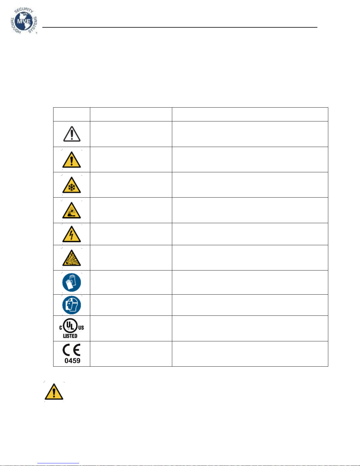
Symbols Used in this Manual
This manual includes the following symbols:
Symbol
Title
Description
Caution
Signifies a CAUTION of a potentially hazardous
situation when operating the device that may result
in minor to moderate injury or property damage.
Warning
Signifies a WARNING of a potentially hazardous
situation when operating the device that may result
in serious injury or property damage.
Warning; Low
Temperature
Indicates low temperature or freezing conditions.
Take care to avoid exposure to skin, eyes, and
clothing.
Warning; Asphixiating
Atmosphere
Indicates the potential for an oxygen-depleted
atmosphere due to nitrogen vapor. Take care to
operate device in a well-ventilated area.
Warning; Electricity
Indicates a potential electrical hazard. Take care to
avoid contact with electricity.
Warning; Explosive
Indicates a potential explosive hazard. The
expansion ratio of liquid nitrogen to gas is 1:700 and
can cause explosive conditions if placed into a
Wear Protective Gloves
Thermal gloves must be worn during indicated
procedures.
Wear a Face Shield
A face shield must be worn during indicated
procedures.
UL Listed Mark
Chart Cryogenic Freezers are conform to relevant
UL safety standards.
CE Mark
Chart Cryogenic Freesers are assessed to meet
safety, health, and environmental protection
requirements for Europe.
• WARNING: Do not modify this equipment without authorization of the
manufacturer.
MVE Biological Systems
TEC 3000 Operating and Maintenance Freezer Manual
13289499 Rev G • 6
Liquid Nitrogen Safety
Liquid nitrogen (LN2) is used in Chart Cryogenic Freezers as a refrigerant. Understanding
potential hazards and following safety precautions is important when handling LN2 and these
freezers.
Nitrogen is a colorless, odorless, and tasteless gas that makes up approximately 78.1% of the
Earth’s atmosphere in its gaseous state. LN2 becomes vapor at temperatures greater than -320.8°F
(-196°C). In liquid state, nitrogen has a temperature range from -320.4°F to -346°F (-195.8°C to 210°C).
• Nitrogen vapor is a potential asphyxiant as it displaces Oxygen (O2) in confined
spaces. Rapid suffocation can occur without warning in an Oxygen-deficient
atmosphere (less than 19.5% O2). Chart Cryogenic Freezers must be installed
and operated in well-ventillated areas.
• DO NOT vent container in confined spaces.
• DO NOT enter confined spaces where excess nitrogen gas may be present.
• If exposure has occurred move to ventillated area or fresh air. If breathing is
difficult, supplement oxygen may be required. If not breathing, give artificial
respiration. SEEK IMMEDIATE MEDICAL ATTENTION.
• Contact with liquid nitrogen or uninsulated equipment containing nitrogen can
result in cold contact burns or tissue damage. Nitrogen vapor can cause
damage to skin or eyes.
• In case of frostbite, warm area with warm water not exceeding 105°F (40°C) and
SEEK IMMEDIATE MEDICAL ATTENTION.
• Never place LN2 in a sealed container without a pressure relief device. The
expansion ratio of liquid nitrogen to gaseous nitrogen is 1 to 700 (1 cubic foot of
liquid nitrogen becomes 700 cubit feet of gaseous nitrogen when evaporated).
Recommended protective clothing
• Cryogenic gloves (loose fitting)
• Full-face shield or chemical splash goggles
• Cryogenic apron
• Long sleeve shirt and cuffless pants
• Closed toe shoes (no sandals)

MVE Biological Systems
TEC 3000 Operating and Maintenance Freezer Manual
13289499 Rev G • 6
Equipment Usage
Cryogenic containers must be operated in accordance with the manufacturer/supplier instructions.
Cryogenic Dewars must be kept in a well- ventilated area protected from weather and away from heat
sources. In applications that use a modular liquid cylinder as a source of LN2, the supply will need to be
replenished at regular intervals to ensure proper operation of the freezer. When exchanging liquid
cylinders, follow the below procedure:
1.
Allow all plumbing components to warm to room temperature before attempting to
change supplies.
2.
Close all valves associated with the liquid supply cylinder.
3.
Relieve pressure in the plumbing assembly by initiating a brief fill by either pressing “Start
Fill” or using the manual fill button.
4.
Loosen the plumbing connection for the transfer hose at the liquid cylinder.
5.
Remove empty liquid cylinder and replace with full liquid cylinder pressurized to 22 - 35
psig (1.52 - 2.41 bar).
6.
Attach the transfer hose to the plumbing connection on the liquid cylinder. Ensure that the
hose is connected to the connection labeled “LIQUID”.
7.
Tighten the transfer hose plumbing connection at the liquid cylinder.
8.
Open the liquid supply valve on the liquid cylinder.
9.
Inspect plumbing for audible and visual leaks. Repair if necessary.
10.
Manually initiate a fill to verify proper operation.
Recommended First Aid
Every site that stores and uses LN2 should have an appropriate Material Safety Data Sheet (MSDS)
present. The MSDS may be obtained from the LN2 distributor. The MSDS will specify the symptoms of
overexposure and first aid to be used. Here is a typical summary.
If symptoms of asphyxia such as headache, drowsiness, dizziness, excitation, excess
salivation, vomiting, or unconsciousness are observed, remove to fresh air. If breathing has
stopped, give artificial respiration. CALL A PHSYICIAN IMMEDIATELY. If breathing is
difficult, supplemental oxygen maybe required. If exposure to cryogenic liquids or cold vapor
occurs, restore tissue to normal, body temperature (37°C) as rapidly as possible, and then
protect the injured tissue from further damage and infection.
Rapid warming of the affected areas is best achieved by bathing it in warm water. The
temperature of the water used should not exceed 40°C. Under no circumstances should the
frozen part be rubbed either before or after warming. If the eyes are involved, flush them
thoroughly with warm water for at least 15 minutes. In case of massive exposure, remove
clothing while showering with warm water. The patient should not drink alcohol or smoke.
CALL A PHYSICIAN IMMEDIATELY.

MVE Biological Systems
TEC 3000 Operating and Maintenance Freezer Manual
13289499 Rev G • 7
4. Certifications and Listings
All fully automatic Chart MVE cryogenic freezer systems equipped with TEC 3000 controllers are UL
Listed for the United States and Canada and CE marked to the Low Voltage Directive (LVD). Specially
designated freezer models are also CE marked to the Medical Device Directive (MDD). The LVD is
European Union directive regulating the construction and operation of electrical equipment that is not
considered a medical device. The MDD is the European Union directive regulating medical device
construction and operation. These listings and certifications encompass the entire freezer system, and
not just the electronic controller.
Authorized Representative:
Medical Product Services GmbH
Borngasse 20
35619 Braunfels, Germany
Chart MVE brand manufactured liquid nitrogen freezers covered in this manual are non-hazardous, open
mouth vacuum insulated Dewars. They are constructed of stainless steel and aluminum and specifically
designed to hold liquid nitrogen. They are not subject to any pressure vessel codes as they are open to
atmospheric pressure.
MVE liquid nitrogen containers are shipped empty without liquid nitrogen or any hazardous material from
our factory. An MSDS is not available for the final formed and welded assembly. An MSDS on the
stainless steel or aluminum alloys used is available but is not specific for the complete manufactured
vessel.

MVE Biological Systems
TEC 3000 Operating and Maintenance Freezer Manual
13289499 Rev G • 8
5. Product Information
This section will give an overview of Chart MVE cryogenic freezers and components.
Chart MVE offers a wide range of LN2 freezers with TEC 3000 controllers that can accommodate a
variety of inventory systems designed to meet all of your cryogenic storage needs. Each freezer is a
hand-made, double-walled, vacuum insulated stainless steel Dewar designed to maintain temperature
with minimal LN2 evaporation.
Intended Use
Chart Cryogenic Freezers that have “MDD” in the model name are certified medical devices
according to the Medical Device Directive (93/42/EEC) and are intended to maintain cryogenic
temperatures for the purpose of storing blood, other body liquids, organs, parts of organs, or body
tissues. This equipment has been tested and found to comply applicable safety and performance
standards.
The general purpose cryogenic storage models are intended for professional use in research
applications.
5.1.
MVE Freezer Models
There are several series, or groups, of freezers, each of which offer specialized features and
functionality. Each freezer has a descriptive name from which the highlighted features and
performance specifications can be determined.
MVE (Series)(Capacity)(Turn-tray?)-(Temp?)(Cabinet?)(Full Auto?)-(Gas Bypass?)-(Battery Backup?)
Series
MVE Freezer Series (i.e. 800, 1500, 1800)
Capacity
Approximate 1.2 or 2.0 mL vial capacity in thousands
Turn-tray
Shape of turn-tray dividers, HE and HEco series only; P = pie-shaped, R =
rectangular
Temp
“Top box” temperature rating, if applicable; -150°C or -190°C
Cabinet
C = cabinet model, if applicable
Full Auto
AF = Automatic Fill
Gas Bypass
GB = Hot Gas Bypass, if applicable
Battery Backup
BB = Battery Backup*
Medical Device
Directive
MDD = European Union directive regulating medical device construction
and operation.
*Battery Backup is standard ONLY for Medical Device Directive freezers.
Example: MVE 1536P-190F-GB-BB-MDD
MVE 1500 Series freezer with capacity for approximately 36,000 vials, pieshaped turn-tray dividers, -190°C temperature rating, equipped with a TEC 3000,
Hot Gas Bypass, and Battery Backup.
The Battery Backup can be added as an optional accessory for all other models.
Example: MVE 1536P-190AF-GB
MVE 1500 Series freezer with capacity for approximately 36,000 vials, pieshaped turn-tray dividers, -190°C temperature rating, equipped with a TEC 3000,
Hot Gas Bypass.
MVE Biological Systems
TEC 3000 Operating and Maintenance Freezer Manual
13289499 Rev G • 9
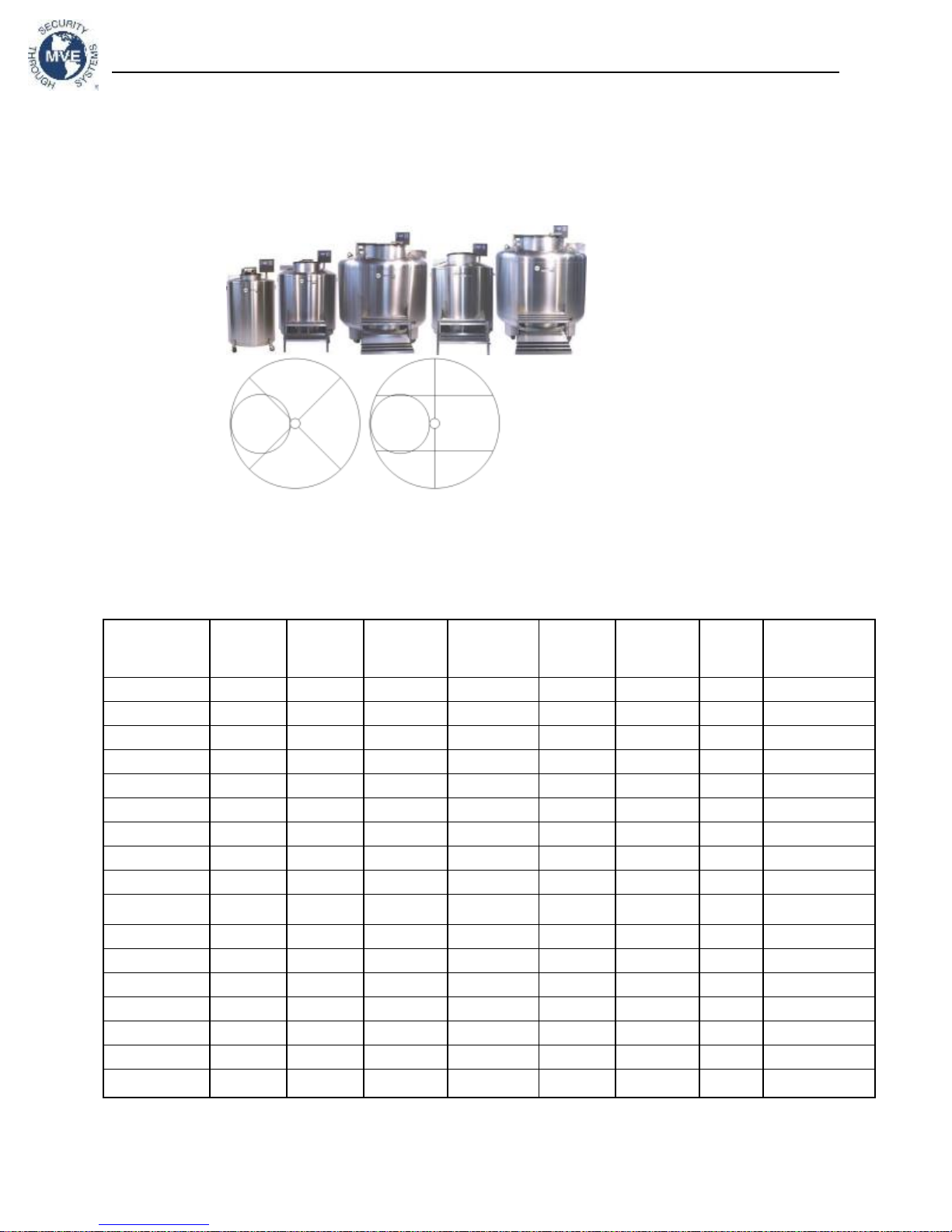
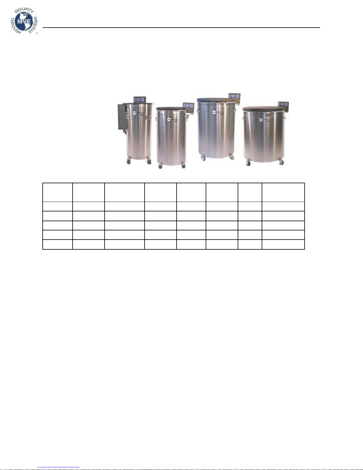
5.1.1.
MVE High Efficiency / Vapor Series
The MVE High Efficiency / Vapor Series freezers will maintain a vapor storage
temperature of either -150°C or -190°C with minimal LN2 evaporation while
accommodating a wide variety of inventory systems.
Figure 1: Top-view of HE Freezer showing offset neck and P and R turn-trays
Note: The values in the table for internal turn trays on the High Efficiency Freezers have a tolerance of +/- .25”
(6mm).
Freezer Model
Minimum
Door
Width
in. (mm)
Minimu
m
Ceiling
Height
Liftover
Height
in. (mm)
Turn-tray
Platform
Height
In (mm)
Weight
Empty
lbs. (kg)
Weight
Liquid Full
lbs. (kg)
Qty of
Casters
Direct Load per
Caster (Full)
lbs. (kg)
MVE 815P-150
32 (813)
75.1 (1908)
47.3 (1202)
6 (152)
475 (215)
1134 (514)
4
284 (129)
MVE 815P-190
32 (813)
75.1 (1908)
47.3 (1202)
6 (152)
475 (215)
1134 (514)
4
284 (129)
MVE 818P-190
32 (813)
84.2 (2138)
51.6 (1310)
6 (152)
495 (225)
1168 (530)
4
292 (133)
MVE 819P-190
32 (813)
90.1 (2289)
55.3 (1405)
6 (152)
515 (234)
1340 (608)
4
335 (152)
MVE 1536P-150
42 (1066)
83.2 (2115)
37.1 (944)
9 (228)
690 (313)
2037 (924)
4
509 (231)
MVE 1536P-190
42 (1066)
83.2 (2115)
37.1 (944)
9 (228)
690 (313)
2037 (924)
4
509 (231)
MVE 1539P-190
42 (1066)
87.8 (2230)
39.2 (995)
9 (228)
720 (327)
2140 (971)
4
535 (243)
MVE 1879P-150
60 (1524)
88.8 (2256)
38.7 (983)
9.5 (242)
1585 (719)
4458 (2022)
4
1115 (506)
MVE 1879P-190
60 (1524)
90.3 (2294)
40.2 (1021)
9.5 (242)
1721 (781)
4830 (2191)
4
1146 (520)
MVE 1892P-190
60 (1524)
100 (2540)
45.2 (1146)
9.5 (228)
1721 (781)
4875 (2211)
4
1219 (553)
MVE 1539R-150
42 (1066)
83.2 (2115)
37.1 (944)
9 (228)
690 (313)
2037 (924)
4
509 (231)
MVE 1542R-150
42 (1066)
87.8 (2230)
39.2 (995)
8 (203)
720 (327)
2140 (971)
4
535 (243)
MVE 1542R-190
42 (1066)
87.8 (2230)
39.2 (995)
9 (228)
720 (327)
2140 (971)
4
535 (243)
MVE 1881R-150
60 (1524)
88.8 (2256)
38.7 (983)
9.5 (242)
1606 (728)
4479 (2032)
4
1120 (508)
MVE 1881R-190
60 (1524)
88.9 (2257)
38.8 (985)
9.5 (242)
1721 (781)
4830 (2192)
4
1208 (548)
MVE 1894R-150
60 (1524)
98.6 (2504)
43.8 (1112)
9.5 (242)
1721 (781)
4875 (2211)
4
1219 (553)
MVE 1894R-190
60 (1524)
98.6 (2504)
43.8 (1112)
9.5 (242)
1721 (781)
4875 (2211)
4
1219 (553)
MVE Biological Systems
TEC 3000 Operating and Maintenance Freezer Manual
13289499 Rev G • 10
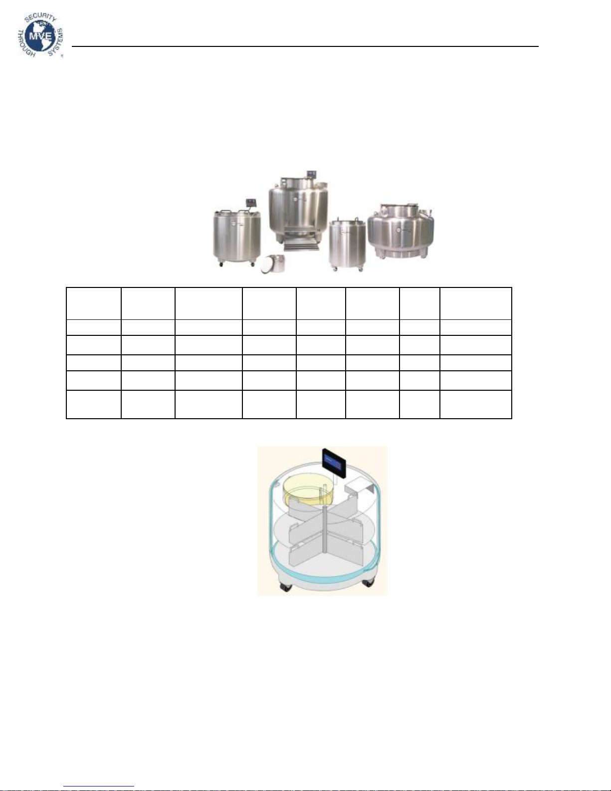
5.1.2.
MVE Series
The MVE Series freezers are designed primarily for liquid phase storage, but can be
used for vapor phase storage with the vapor storage accessory package. The wide neck
opening allows easy access to stored samples. In vapor phase storage, these freezers
will maintain a top box temperature of -90oC to -125°C.
Freezer
Model
Minimum
Door Width
in. (mm)
Minimum
Ceiling Height
in. (mm)
Liftover
Height
in. (mm)
Weight
Empty
lbs. (kg)
Weight
Liquid Full
lbs. (kg)
Qty of
Casters
Direct Load per
Caster (Full)
lbs. (kg)
MVE 205
20.4 (518)
71.1 (1806)
41 (1041)
195 (88)
365 (166)
4
91 (42)
MVE 510
23.9 (606)
71.7 (1822)
41.6 (1057)
281 (127)
577 (262)
4
144 (66)
MVE 616
27.4 (696)
71.5 (1816)
41.4 (1051)
310 (145)
748 (339)
4
187 (85)
MVE 1426
33.8 (858)
70.1 (1781)
40 (1016)
490 (222)
1181 (536)
4
295 (134)
MVE 1839
46.1 (1171)
92.3 (2345)
47.3 (1202)
750 (341)
1950 (885)
6
325 (148)
MVE Biological Systems
TEC 3000 Operating and Maintenance Freezer Manual
13289499 Rev G • 11
5.1.3.
MVE Stock Series
The MVE Stock Series freezers are designed primarily for storage of either vials or
straws on canes in liquid nitrogen, but can also be used for vapor phase storage with the
vapor storage accessory package. Dual lids on the MVE 1318 and two-tier turn-trays in
the MVE 816P-2T-190 and the MVE 1877P-2T-150 are example features of these
freezers built for durability and ergonomic sample retrieval.
Freezer
Model
Minimum
Door Width
in. (mm)
Minimum
Ceiling Height
in. (mm)
Liftover
Height
in. (mm)
Weight
Empty
lbs. (kg)
Weight
Liquid Full
lbs. (kg)
Qty of
Casters
Direct Load per
Caster (Full)
lbs. (kg)
MVE 808
31 (787)
65.1 (1653)
39.1 (992)
250 (114)
660 (300)
3
220 (100)
MVE 816P2T-190
32 (813)
59.5 (1512)
48.3 (1227)
475 (215)
1155 (524)
4
288.75 (131)
MVE 1318
42 (1067)
62.8 (1595)
43.6 (1107)
469 (213)
1328 (602)
3
332 (201)
MVE
1842P-150
60 (1524)
73 (1853)
42.5 (1078)
1167 (530)
2798 (1270)
4
699.5 (317.5)
MVE
1877P-2T150
60 (1524)
67.5 (1716)
36.3 (923)
1600 (726)
4094 (1857)
4
1023.5 (464.25)
Figure 2: Diagram showing innovative two-tier turn-tray designed to
maximize storage capacity while minimizing floor space.
MVE Biological Systems
TEC 3000 Operating and Maintenance Freezer Manual
13289499 Rev G • 12
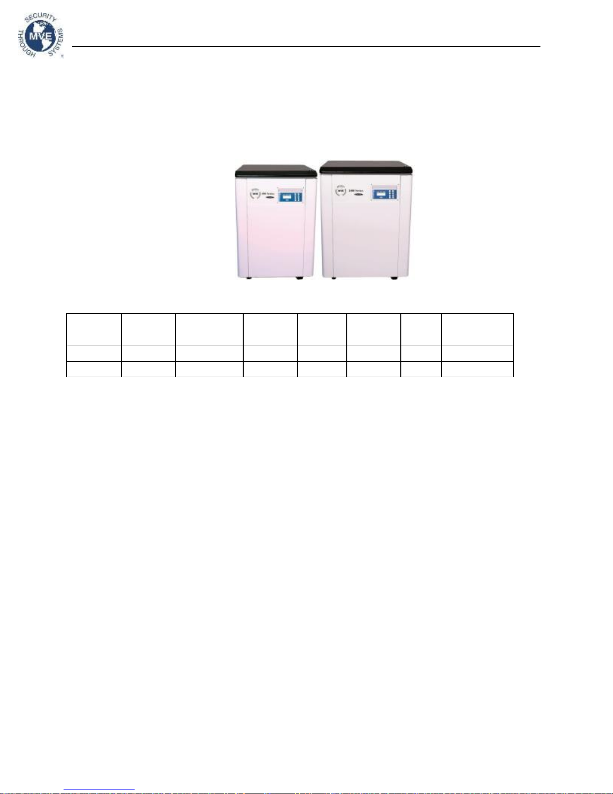
5.1.4.
MVE Cabinet Series
The MVE Series freezers are designed primarily for liquid phase storage, but can be
used for vapor phase storage with the vapor storage accessory package. The wide neck
opening allows for ergonomic sample retrieval and the aesthetic square cabinet design
fits snugly into tight corners.
Freezer
Model
Minimum
Door Width
in. (mm)
Minimum
Ceiling Height
in. (mm)
Liftover
Height
in. (mm)
Weight
Empty
lbs. (kg)
Weight
Liquid Full
lbs. (kg)
Qty of
Casters
Direct Load per
Caster (Full)
lbs. (kg)
MVE 616
28 (711)
71.5 (1816)
41.4 (1051)
352 (160)
785 (356)
4
196 (89)
MVE 1426
34.8 (883)
70.3 (1786)
40.2 (1021)
530 (240)
1198 (543)
4
300 (136)
MVE Biological Systems
TEC 3000 Operating and Maintenance Freezer Manual
13289499 Rev G • 13
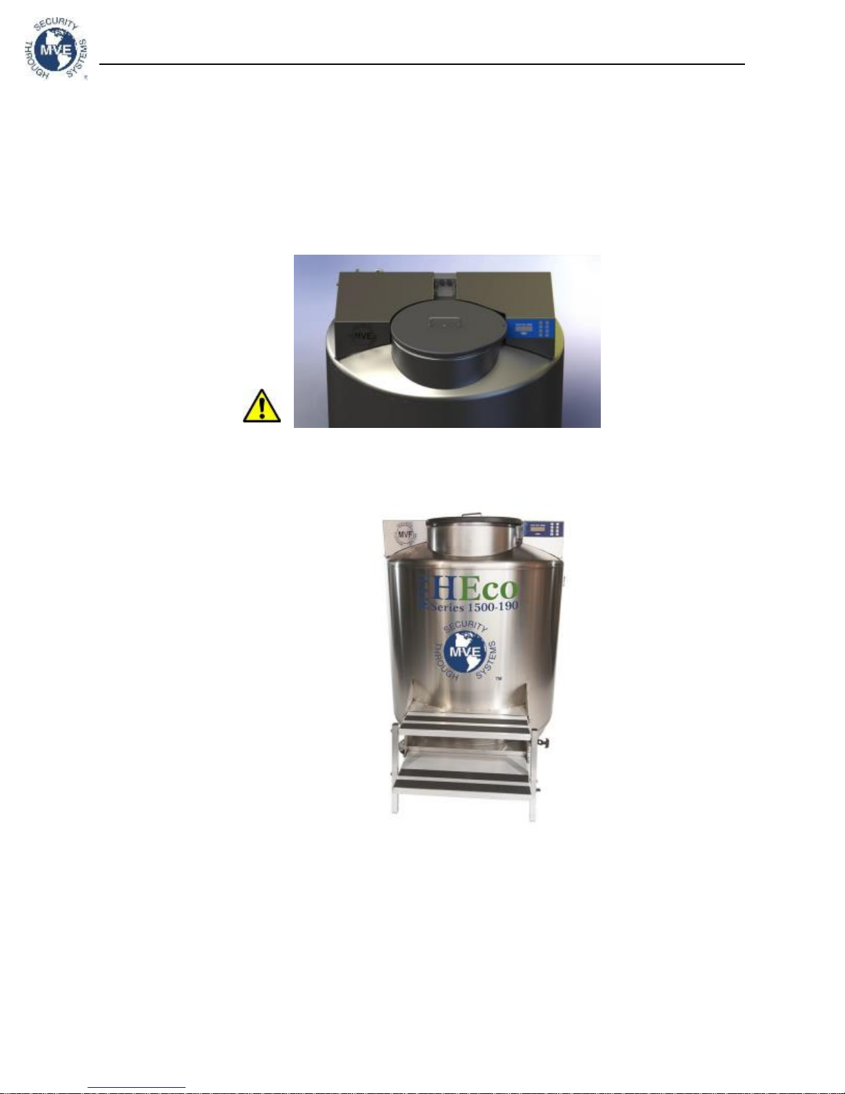
5.1.5.
MVE HEco Series
The MVE HEco Series freezers will maintain a vapor storage temperature of -190°C with
minimal LN2 evaporation while accommodating a wide variety of inventory systems. This
freezer is designed for easier access to the plumbing stack. This also allows for lower
height clearance. The HEco is available only in the automatic fill version.
Model description example MVE HECO 1536P-190AF-GB
CAUTION: Pinch hazard, use caution when opening and closing the plumbing
and electrical enclosures.
MVE Biological Systems
TEC 3000 Operating and Maintenance Freezer Manual
13289499 Rev G • 14
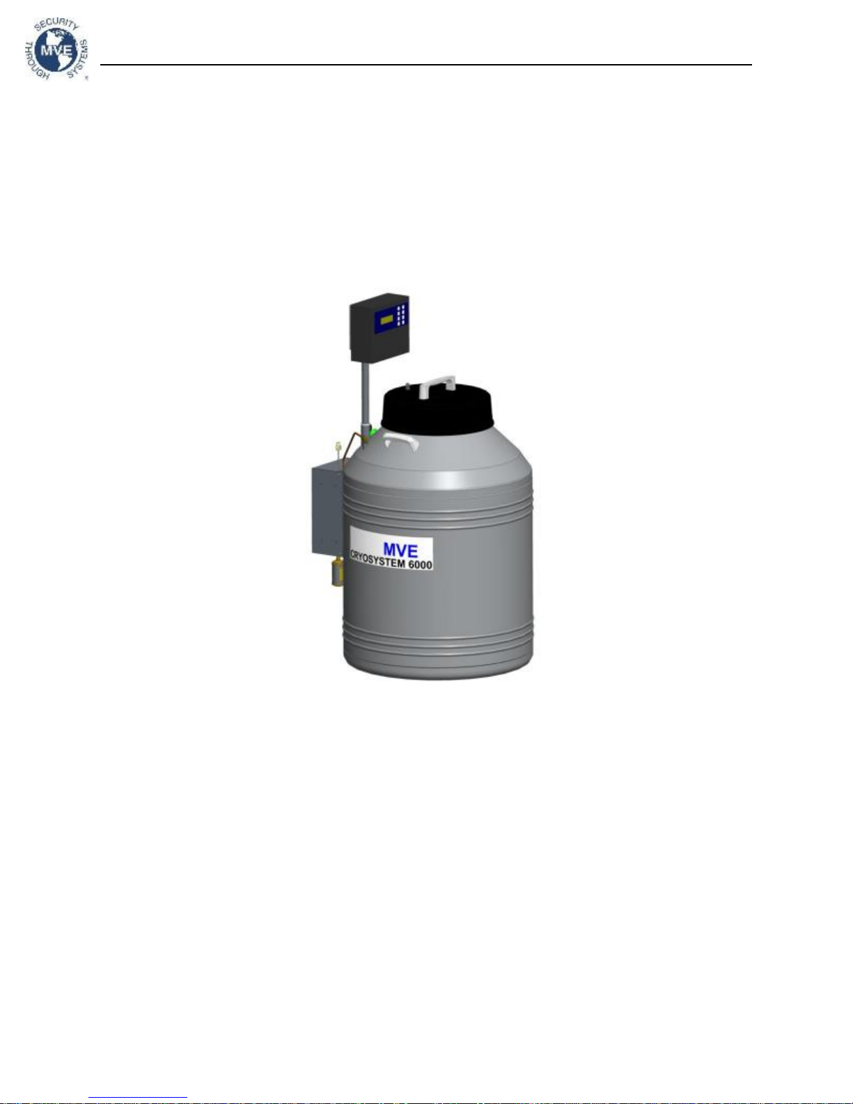
5.1.6.
CryoSystem 6000 Full Auto
The MVE CryoSystem is designed primarily for liquid phase storage. The durable,
tamper-proof lid design with its wide neck opening allows for ergonomic sample retrieval.
The unique design is manufactured with the TEC3000 and plumbing system.
CryoSystem 6000 Full Auto with Gas bypass and TEC3000
MVE Biological Systems
TEC 3000 Operating and Maintenance Freezer Manual
13289499 Rev G • 15
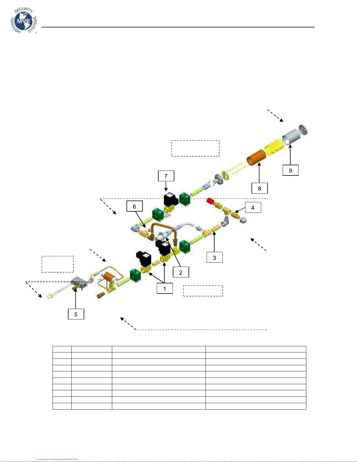
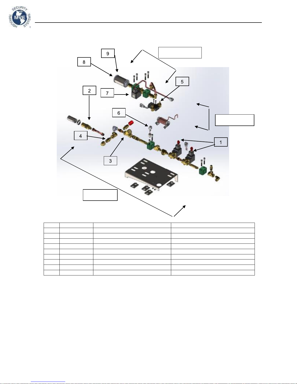
5.2
Plumbing Assembly
The plumbing assembly carries and regulates the flow of LN2 from the liquid supply through the
annular fill line, and into the freezer. There are three plumbing assembly configurations; one for
the HE/Stock Series, one for the HEco Series, and one for the MVE/Cabinet Series. Each one
of these configurations are comprised of three main circuits: fill circuit, purge circuit, and
optional gas bypass circuit.
Key
Part Number
Component
Spec Details
1 14224611S
Fill Solenoid Valve
24 VDC, R ≈ 70 Ω (single), 35 Ω (dual)
2 1810032
Pressure Relief Valve
50 PSI (3.45 bar)
3 11648945
Inline Filter
40-micron
4 1110052
Fill Transfer Hose Connections
½ in. ODT, 45° flare, ¼ in. MPT
5 13284954S
Purge (3-way) Solenoid Valve
24 VDC, R ≈ 140 Ω
6 10713400
Gas Bypass Temp Sensor
Pt-1000 RTD
7 14224611S
Gas Bypass Solenoid Valve
24 VDC, R ≈ 70 Ω
8 11499812
Gas Bypass Muffler
-
9 11885449
Gas Bypass Muffler Deflector
-
HE Series / CryoSystem 6000 Plumbing Assembly
Hot Gas Bypass
Circuit
Purge
Circuit
Fill Circuit
MVE Biological Systems
TEC 3000 Operating and Maintenance Freezer Manual
13289499 Rev G • 16
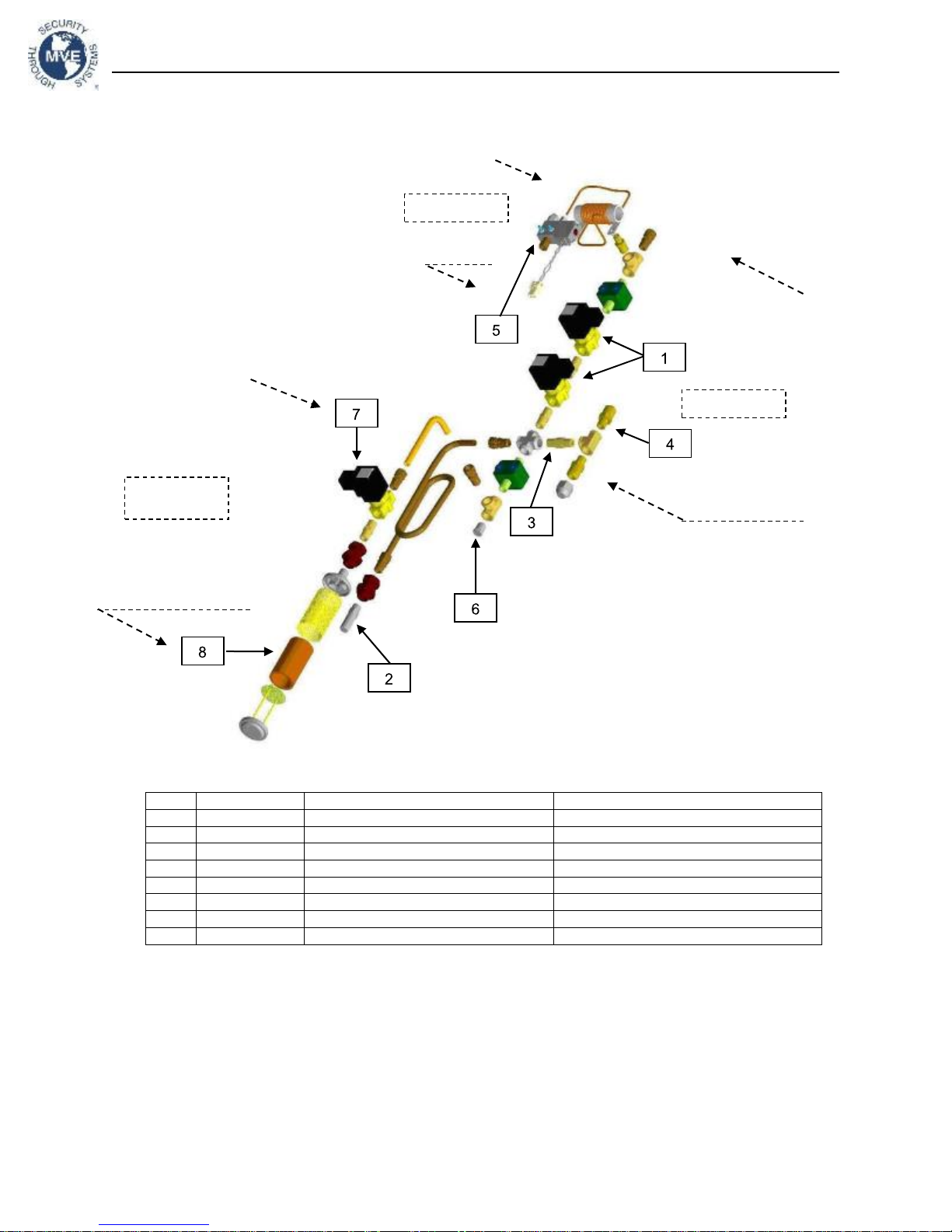
MVE Series Plumbing Assembly
Key
Part Number
Component
Spec Details
1 14224611S
Fill Solenoid Valve
24 VDC, R ≈ 70 Ω (single), 35 Ω (dual)
2 1810032
Pressure Relief Valve
50 PSI (3.45 bar)
3 11648945
Inline Filter
40-micron
4 1110052
Fill Transfer Hose Connections
½ in. ODT, 45° flare, ¼ in. MPT
5 13284954S
Purge (3-way) Solenoid Valve
24 VDC, R ≈ 140 Ω
6 10713400
Gas Bypass Temp Sensor
Pt-1000 RTD
7 14224611S
Gas Bypass Solenoid Valve
24 VDC, R ≈ 70 Ω
8 11499812
Gas Bypass Muffler
-
Purge Circuit
Fill Circuit
Hot Gas
Bypass Circuit

MVE Biological Systems
TEC 3000 Operating and Maintenance Freezer Manual
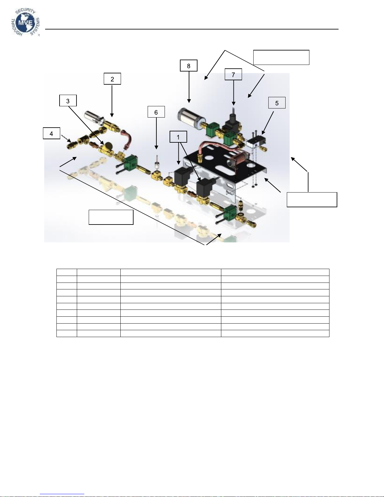
13289499 Rev G • 17
Key
Part Number
Component
Spec Details
1 14224611S
Fill Solenoid Valve
24 VDC, R ≈ 70 Ω (single), 35 Ω (dual)
2 1810032
Pressure Relief Valve
50 PSI (3.45 bar)
3 20669243
Y Strainer (Filter)
40-micron
4 1110052
Fill Transfer Hose Connections
½ in. ODT, 45° flare, ¼ in. MPT
5 13284954S
Purge (3-way) Solenoid Valve
24 VDC, R ≈ 140 Ω
6 10713400
Gas Bypass Temp Sensor
Pt-1000 RTD
7 14224611S
Gas Bypass Solenoid Valve
24 VDC, R ≈ 70 Ω
8 11499812
Gas Bypass Muffler
-
9 11885449
Gas Bypass Muffler Deflector
-
HEco 800 Series Plumbing Assembly
Bypass Circuit
Purge Circuit
Fill Circuit
MVE Biological Systems
TEC 3000 Operating and Maintenance Freezer Manual
13289499 Rev H • 18
Bypass Circuit
Purge Circuit
Fill Circuit
HEco 1500 Series Plumbing Assembly
Key
Part Number
Component
Spec Details
1 14224611S
Fill Solenoid Valve
24 VDC, R ≈ 70 Ω (single), 35 Ω (dual)
2 1810032
Pressure Relief Valve
50 PSI (3.45 bar)
3 20669243
Y Strainer (Filter)
40-micron
4 1110052
Fill Transfer Hose Connections
½ in. ODT, 45° flare, ¼ in. MPT
5 13284954S
Purge (3-way) Solenoid Valve
24 VDC, R ≈ 140 Ω
6 10713400
Gas Bypass Temp Sensor
Pt-1000 RTD
7 14224611S
Gas Bypass Solenoid Valve
24 VDC, R ≈ 70 Ω
8 11499812
Gas Bypass Muffler
-
9 11885449
Gas Bypass Muffler Deflector
-
MVE Biological Systems
TEC 3000 Operating and Maintenance Freezer Manual
13289499 Rev H • 19
HEco 1800 Series Plumbing Assembly
Key
Part Number
Component
Spec Details
1 14224611S
Fill Solenoid Valve
24 VDC, R ≈ 70 Ω (single), 35 Ω (dual)
2 1810032
Pressure Relief Valve
50 PSI (3.45 bar)
3 20669243
Y Strainer (Filter)
40-micron
4 1110052
Fill Transfer Hose Connections
½ in. ODT, 45° flare, ¼ in. MPT
5 13284954S
Purge (3-way) Solenoid Valve
24 VDC, R ≈ 140 Ω
6 10713400
Gas Bypass Temp Sensor
Pt-1000 RTD
7 14224611S
Gas Bypass Solenoid Valve
24 VDC, R ≈ 70 Ω
8 11499812
Gas Bypass Muffler
-
9 11885449
Gas Bypass Muffler Deflector
-
Bypass Circuit
Purge Circuit
Fill Circuit
MVE Biological Systems
TEC 3000 Operating and Maintenance Freezer Manual
13289499 Rev H • 20
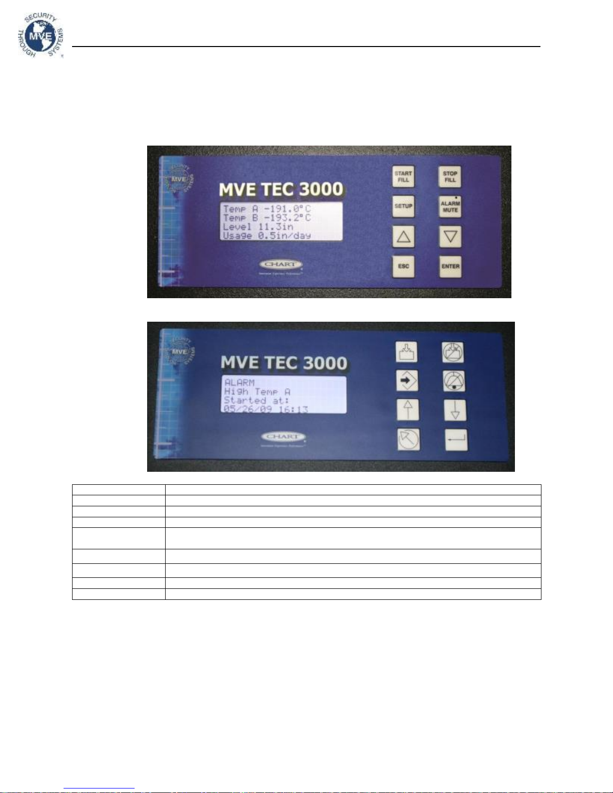
5.3
TEC 3000 Display
The TEC 3000 front panel display is the primary user interface for the TEC 3000. There are two
display options: text or symbolic.
Text Display
Symbolic Display
LDC Display
20 x 4 LCD with backlight
START FILL Key
Used to manually initiate a fill
STOP FILL Key
Used to manually terminate a fill – Disables Auto Fill for 30 minutes
SETUP Key
Used to access Setup Menus and parameters
ALARM MUTE Key
Used to silence the audible alarm for 30 minutes. Will reset the latching alarm once it has
been corrected
▲ Key
Used to increase parameter values or to toggle “YES/NO” or “ON/OFF” values
▼ Key
Used to decrease parameter values or to toggle “YES/NO” or “ON/OFF” values
ESC Key
Used to escape or exit a menu or menu level
ENTER Key
Used to select a menu or value or save a setting change
MVE Biological Systems
TEC 3000 Operating and Maintenance Freezer Manual
13289499 Rev H • 21
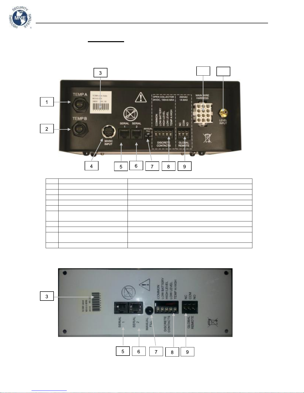
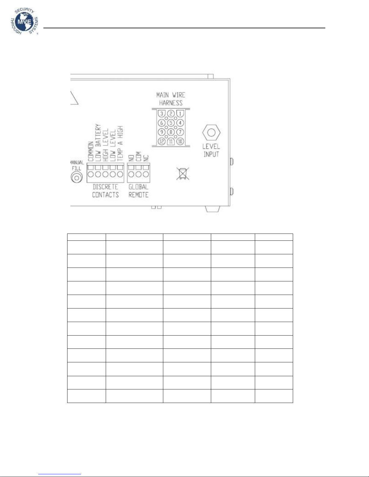
5.4
TEC 3000 Stand Alone Back Panel / Physical Connections
The TEC 3000 physical and electrical connections are located on the bottom of the stand-alone
(non-cabinet) controller and on the back panel of the cabinet controller.
1 Temp A Port
Connection for Temp A probe
2 Temp B Port
Connection for Temp B probe
3 Serial Number Barcode
TEC 3000 serial number written below barcode
4 30 VDC Power Input
Main power supply connection
5 Serial 1 Port
RJ-45 connection for Serial/COM 1
6 Serial 2 Port
RJ-45 connection for Serial/COM 2
7 Manual Fill Button
Used to manually fill freezer. When depressed and held, the
fill valves open. When released, the fill valves close.
8 Discrete Contacts
Open collector alarm terminals
9 Global Remote
Dry contact alarm terminals
10
Wire Harness Connection
12-pin wire harness connection to plumbing assembly, lid
switch, and battery backup
11
Level Connection
Level signal input. Clear, vinyl tube connects to hose barb
5.4.1
TEC3000 HEco/Cabinet Physical Connections
10
11
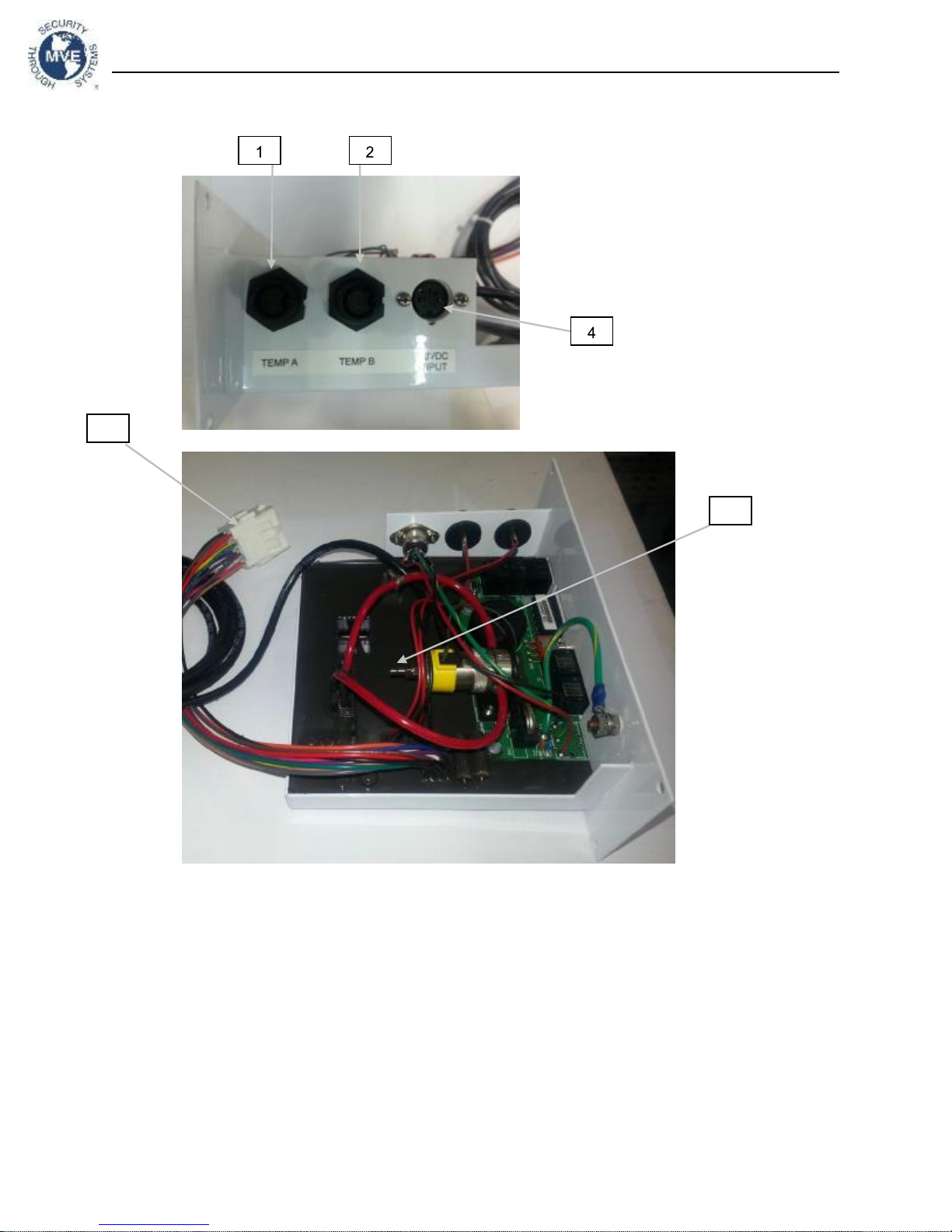
MVE Biological Systems
TEC 3000 Operating and Maintenance Freezer Manual
13289499 Rev H • 22
11
10
MVE Biological Systems
TEC 3000 Operating and Maintenance Freezer Manual
13289499 Rev H • 23
5.4.2
TEC3000 12-Pin Wiring Harness Connections
POSITION
DESCRIPTION
WIRE COLOR
WIRE GAUGE
LENGTH 1
+24VDC BATTERY
BACKUP
DARK BLUE
18 50" 2
-24VDC BATTERY
BACKUP
ORANGE
18 50" 3 + LID SWITCH
BLACK WHITE
STRIPE
22 96" 4 + FILL VALVE
BROWN
18 82" 5 - FILL VALVE
PURPLE
18 82" 6 - LID SWITCH
RED GREEN
STRIPES
22 96" 7 + PURGE VALVE
YELLOW
20 48"
8
- PURGE VALVE
RED 20 48"
9
+ BYPASS SENSOR
RED 22 67"
10
+ BYPASS VALVE
BLACK
18 75"
11 - BYPASS VALVE
GRAY
18 75" 12
- BYPASS SENSOR
WHITE
22 67"

MVE Biological Systems
TEC 3000 Operating and Maintenance Freezer Manual
13289499 Rev H • 24
5.5
Specifications
TEC 3000 Dimensions (stand-alone)
Length
Width
Height
Weight
9.1 in. (232 mm)
3.5 in. (89 mm)
8.0 in. (203 mm)
6.5 lbs. (2.95 kg)
Display
Type
Size
Resolution
Keypad
Liquid Crystal Display (LCD) with backlight
20 x 4 Character
8 x 5 Pixels per Character
8 keys, Multi-function
Electrical – TEC 3000 Only
Input Voltage
Input Current (max)
Input Current (continuous)
Power Consumption (max)
Power Consumption (continuous)
Fill Valve Output Voltage
Short Protection
30 VDC
5 A
1 A
28 W
6 W
24 VDC
Current limiting, automatic reset
Electrical – Jerome Power Supply (WSL730M V1)
Input Voltage
Input Frequency
Output Voltage
Max Current Capability
Input Current
110 – 230 VAC
50 – 60 Hz
30 VDC
3 A
0.73 A @ 110 VAC
0.35 A @ 230 VAC
Power Requirements – TEC 3000 + Power Supply
Input Voltage
Input Current (max)
Input Current (continuous)
Input Power (max)
Input Power (continuous)
110-230VAC/50-60Hz
.73A@110VAC
.35A@230VAC
30 Watts
8 Watts
TEC 3000 Physical Connections
Temperature Probes
Input Power
Output Power / Sensors / Battery Backup
Serial Ports
2-pin twist lock
5-pin DIN
15-pin AMP
RJ-45, 4-pin RS-485
Temperature Sensor
Type
Quantity
Resistance
Sensitivity
2-wire Platinum RTD (Pt-1000)
2
1000 Ω @ 0°C
3.85 Ω / °C
Temperature Measurement
Resolution
Accuracy – Single Point Calibration *
– Two Point calibration **
Range
0.1°C (0.2°F)
± 1.0°C (1.8°F)
± 2.0°C (3.6°F)
- 200°C to 70°C (- 328°C to 158°F)
Level Measurement
Type
Accuracy
Resolution
Range
Differential Pressure Sensor
± 0.5 in. (13 mm) LN2
0.1 in. (2.5 mm)
3.0 in. to 48 in. (76 mm to 1219 mm)
* Accuracy determined over range of -200°C to -135°C. Accuracy decreases slightly as range increases
** Accuracy determined over a range of -200°C to 0°C. Accuracy decreases slightly as range increase

MVE Biological Systems
TEC 3000 Operating and Maintenance Freezer Manual
13289499 Rev H • 25
5.6
Operating Environment
Ambient Temperature and Relative Humidity
MVE cryogenic freezers are designed to be operated in environments near room temperature
(65°F – 80°F, 18°C – 27°C) and relative humidity below 50%. Due to the large gradient
between LN2 and ambient temperatures, an additional change of a few degrees will not have a
significant impact on the freezer performance. Although temperature changes will affect the
open top MVE and MVE Stock series freezers to a greater degree, it again will not be a
significant effect. The relative humidity should be maintained low enough so that condensation
does not form on the TEC 3000. Elevated humidity levels can lead to excessive condensation
and frost on and around the lid. In situations where the relative humidity is high and
uncontrollable, the lid should be routinely wiped dry to prevent ice formation. Should significant
ice formation develop, thaw as necessary. Refer to the Preventative Maintenance procedures
for details.
Atmospheric Pressure
MVE cryogenic freezers are designed to be operated in environments with atmospheric
pressure range of 8.2 psi (57.2 kPa) to 14.7 psi (101 kPa).
Thermal Load
Since MVE Freezers use LN2 as the refrigerant and do not employ any type of mechanical
refrigeration, the thermal load will be negligible to negative.
MVE Biological Systems
TEC 3000 Operating and Maintenance Freezer Manual
13289499 Rev H • 26
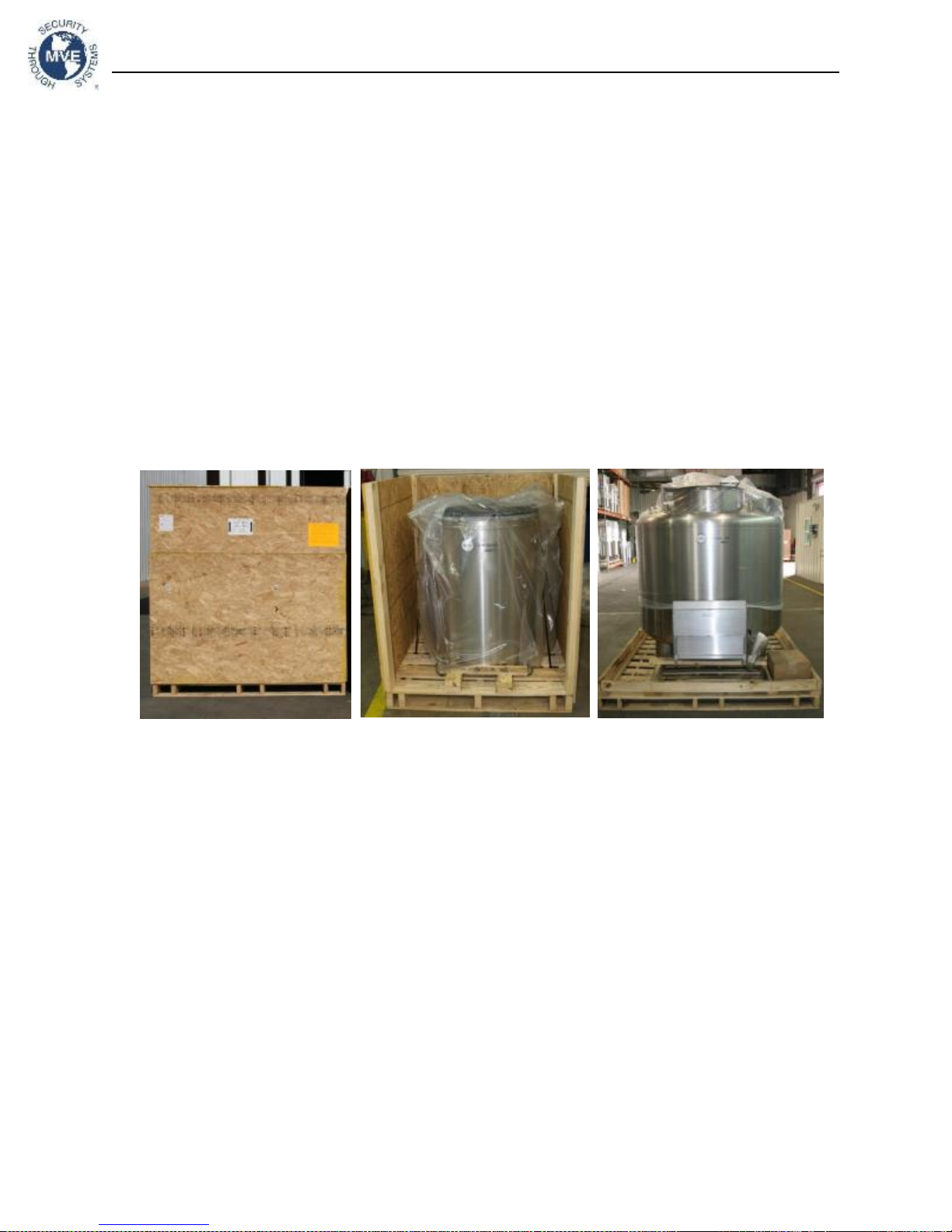
6. Installation and Startup
This section will review the basic receiving, installation, and startup procedures for MVE Freezers. These
instructions can also be applied to set up the CryoSystem 6000 Full Auto. Always inspect the bill of
lading for accuracy and external crate/packaging for damage before accepting the shipment.
Included with each full auto freezer:
•
Literature Packet
o
TEC 3000 Quick Start Reference Guide – PN 13289481
o
Manual Freezer Status Log – PN 10936355
•
TEC 3000 – Packaged in box separately for HE/MVE Series models
•
Transfer hose – 6 ft. – Inside freezer
•
MVE Dipstick – Inside freezer
•
Desiccant bag – To be removed and discarded – Inside freezer
•
Liquid Nitrogen handling instructions
•
MVE Certificate of Quality
MVE Biological Systems
TEC 3000 Operating and Maintenance Freezer Manual
13289499 Rev H • 27
Installation
NOTE: Do not apply power to the TEC 3000 controller or connect an LN2 supply until
later in this procedure to avoid injury or damaging the equipment.
Following the careful uncrating and unpacking of the freezer, install using these basic instructions.
Cabinet Series freezers will be shipped with some of the connections described below already installed.
NOTE: Only install the freezer on a level surface. Never fill freezer and move to another location. Always
fill the freezer where it is to be installed/used.
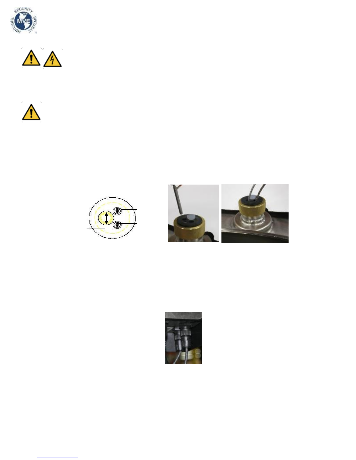
•
Locate the temperature sensor tube assembly that will house the two temperature probes. For
HE, HEco, and some Stock Series freezers, a three-tube temperature sensor assembly will be
installed in the center of the top of the freezer. The two smaller tubes are designed to house the
included temperature probes. The third, larger tube is designed to accommodate a third-party
temperature probe. A silicone plug will be installed in this third tube. If the third tube is going to be
used, simply remove the silicone plug. For the MVE Series (all open top freezers), a dual sensor
tube will be installed along the inside wall of the freezer storage space. The CryoSystem 6000
temperature probes are inserted into the neck area.
•
Insert the two temperature probes into the sensor tubes and position the sensors at the preferred
height in the freezer space. Selecting probe A and B as well as the sensor placement is
adjustable and completely up to the user. MVE does recommend placing sensor (Temp A) at the
“top box” level. This refers to the level in the freezer space where the highest sample is being
stored. If storing vials in boxes, then this would be at the level with the top box. This is
recommended as it will be the warmest temperature experience by samples being stored in the
freezer space.
•
Connect the temperature probes to the TEC 3000 temperature ports using the twist lock
connectors.
•
For HEco models, once the temperature probes are in the desired position the freezer is ready to
be filled. Connect transfer hose to its fill source and proceed to step 2 of the first fill start up
procedure.
•
For HE models, once the temperature probes are in the desired position, apply a small amount of
the silicone sealant, included with the freezer, surrounding the temperature probes where they
enter the sensor tubes. This will help maintain their position and help keep moisture from entering
the freezer storage space. Proceed to the next step.
0.21 inches
(5.3 mm)
0.37 inches
(9.4 mm)
MVE Biological Systems
TEC 3000 Operating and Maintenance Freezer Manual
13289499 Rev H • 28
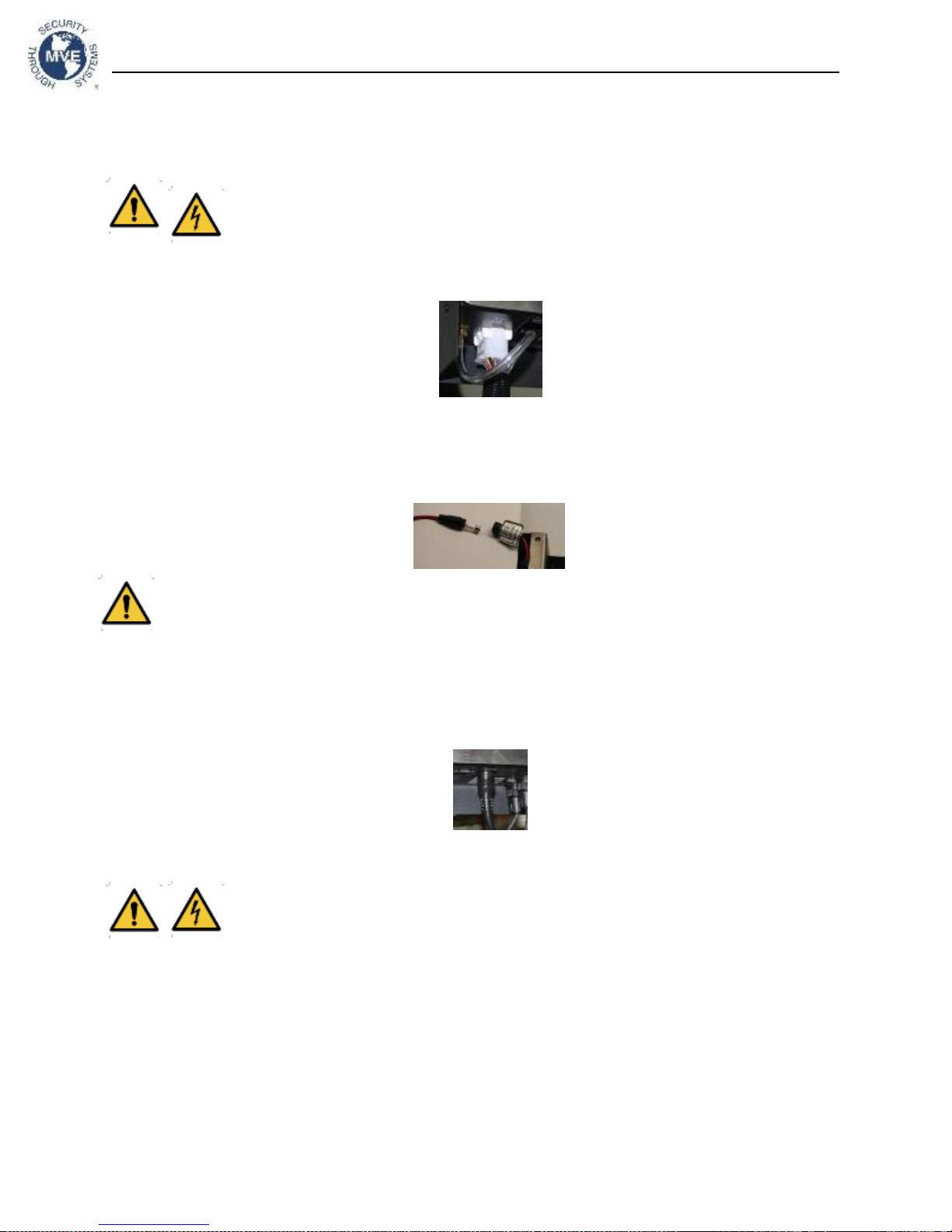
•
Connect the clear vinyl tubing to the TEC 3000 Level Input hose barb and connect the other end
of the tubing to the 3-way purge valve.
•
Ensure all of the plumbing assembly connections to the TEC 3000 wire harness are secure.
NOTE: Do not connect the battery backup (if equipped) to the wire harness until
later in the installation procedure.
•
Connect the 12-pin wire harness to the TEC 3000 wire harness connection.
•
If the freezer is equipped with battery backup measure the voltage at the end connector for
approximately 24VDC to 27VDC; if no voltage is present, the included battery fuse must be
installed before connecting the battery to the main wire harness. Open the battery enclosure and
unscrew the fuse harness. Install the fuse; close the fuse harness and the battery enclosure.
(This is done at the factory but should be verified at installation)
NOTE: Do not connect the battery backup to the main wire harness until the power supply has
been verified to power up the controller
•
Plug in the power supply to an appropriate wall outlet with the proper AC voltage. Avoid wall
outlets that are connected to emergency generator power if possible. Although an uninterruptible
power supply (UPS) is ideal to ensure continuous power, a surge protector or power conditioner
is recommended.
•
Plug the power supply into the TEC 3000 30 VDC power input. The TEC 3000 display should
illuminate and begin the startup sequence.
To avoid risk of electrical shock, this equipment must only be connected to a properly
grounded power source or outlet.
•
Following the startup sequence, the TEC 3000 may start to alarm. This is normal.
• Press “Alarm Mute” to silence the audible buzzer for 30 minutes. For installation and startup
purposes, the alarm buzzer can be disabled; however, be sure to enable it when installation is
complete. For instructions, see the Alarm Buzzer page in Section 6 of this manual.
•
Connect the battery backup to the main wiring harness. While running on outlet power, the TEC
3000 supplies a steady 27 VDC trickle charge to the battery backup. The battery backup may
need to be charged for several hours before it is able to power the TEC 3000.
 Loading...