

Page 1
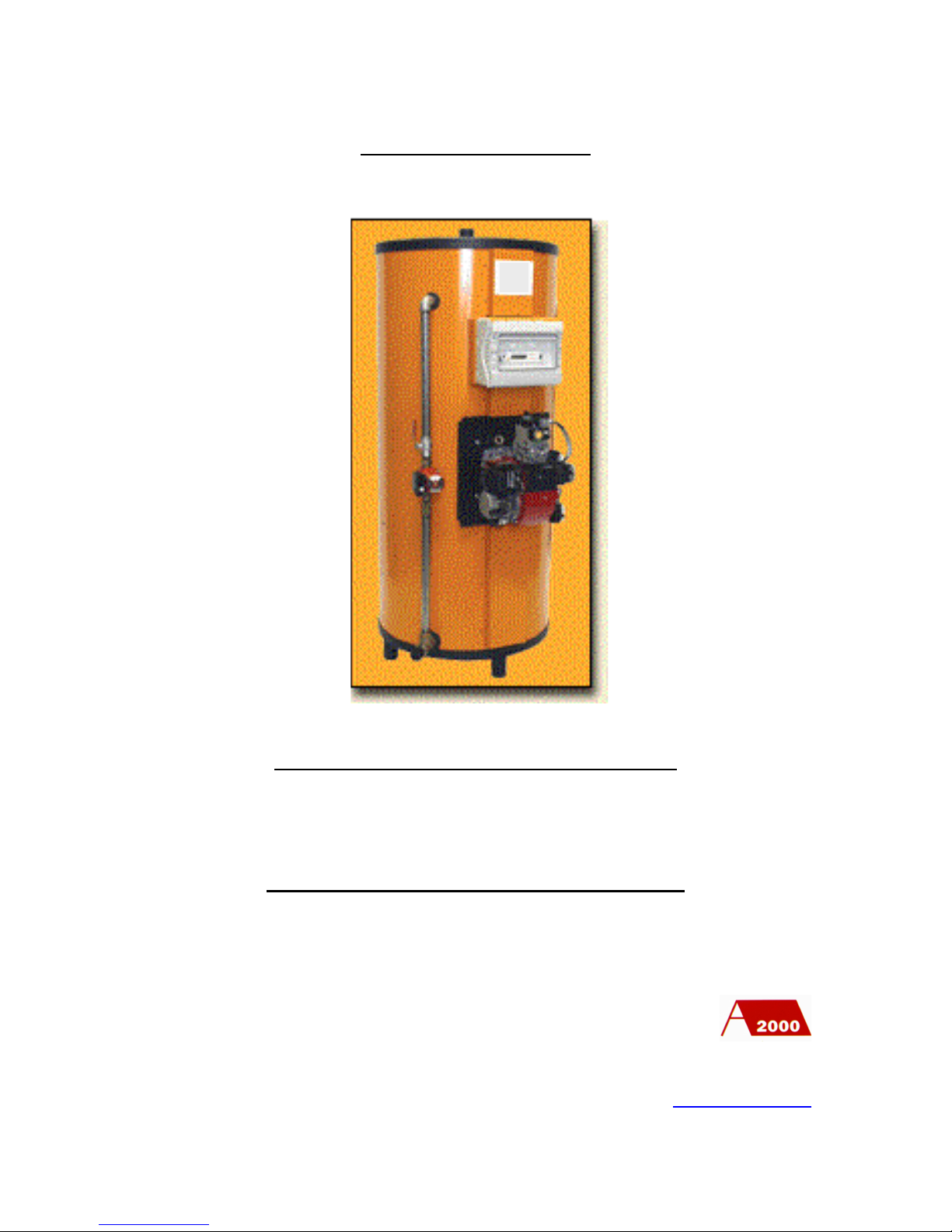
MAX’O GAZ
Condensing water heater
TECHNICAL MANUAL
PO Box 11 Ashton Under Lyne OL6 7TR
+44. (0) 161 621 5960 Fax +44. (0) 161 621 5966
www.atlanticboilers.com
Page 2

2
Page 3

3
CONTENTS
THE COMPONENTS OF THE MAX’O GAZ………….….……………………………………1
BALANCED FLUE AND CONVENTIONAL FLUE MAX’O GAZ FEATURES……….…3
INSTALLATION OF THE MAX’O GAZ………………
…..
……………….……………………5
STANDARD PIPEWORK ARRANGEMENT………….……………………………….………8
PIPEWORK ARRANGEMENT WITH A TANK……
……….
……..……………………………..9
PIPEWORK ARRANGEMENT WITH A BUFFER STORAGE……………………………10
THE GAS PIPEWORK CONNECTIONS…………………………………………………….11
MAX’O GAZ GAS SUPPLY FROM A PRESSURE REGULATING VALVE…………...14
CONVENTIONAL FLUE ARRANGEMENT……………………………………………..…15
BALANCED FLUE CONNECTIONS ON WALL OUTLET………………………………..16
HORIZONTAL BALANCED FLUE…………………..………………………………………17
ELECTRIC CONNECTION……………………………………………………………………19
ELECTRIC DIAGRAM………………………………………………………………………….20
SETTINGS………………………………………………………………………………………..21
CHECKINGS BEFORE STARTING THE WATER HEATER……………………………..24
STARTING THE WATER HEATER…………………………………………………………25
THE COMMISSIONING OF THE MAX’O GAZ……………………………………………27
DEFAULT FINDING CHART…………………………………………………………………30
THE GUARANTEE ON THE MAX’O GAZ………………………………………………….32
PO Box 11 Ashton Under Lyne OL6 7TR
+44. (0) 161 621 5960 Fax +44. (0) 161 621 5966
www.atlanticboilers.com
4
6
8
11
12
13
14
17
18
19
20
22
23
24
28
29
31
34
36
Page 4

4
THE COMPONENTS OF THE MAX’O GAZ
1) COMBUSTION CHAMBER AND HEAT EXCHANGER
- stainless steel combustion chamber
- stainless steel coils of flue tubes
- an access door with ceramic fibre insulation and flame inspection point
2) A STAINLESS STEEL HOT WATER STORAGE
- cold water feed inlet
- hot water supply outlet
- drain outlet
- three sensors points
3) A PRESSURISED GAS BURNER
- aluminium body
- motorised fan air supply
- gas valve with controlled rate of opening
- ignition transformer
- air/gas mixing combustion head
- differential pressure switch
- ignition pressure switch
- control box with ionization flame protection
- balanced flue pressure switch control
4) A CONTROL PANEL
- stop/start switch
- Pack Control regulator
- additional adjustable thermostat
- limit water thermostat set at 95ºC
- burner green run lamp
-
5) AN ENCLOSING JACKET
- 50mm thick glass silk thermal insulation
- enamelled steel jacket in four removable sections
6) OPTIONAL ITEM
-
anti-legionella pump assembly
PO Box 11 Ashton Under Lyne OL6 7TR
+44. (0) 161 621 5960 Fax +44. (0) 161 621 5966
www.atlanticboilers.com
Page 5
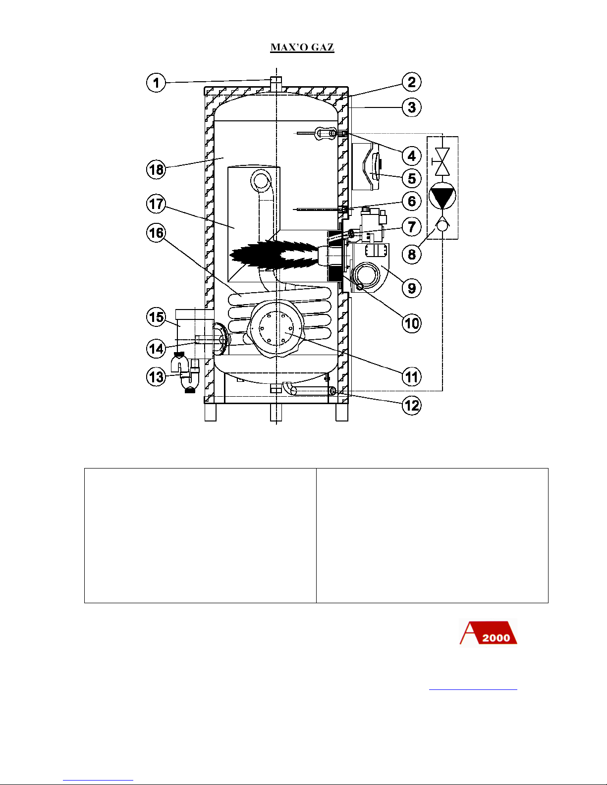
5
1 - Hot water outlet
2 - Mineral wool insulation
3 - Outer jacket
4 - Limit thermostat
5 - Control panel
6 - Control thermostat
7 - Inspection Glass
8 - Anti-legionella package
9 - Burner
10 - Refractory
11 - Inspection cover
12 - Drain point
13 - Condensate outlet
14 - Cold water inlet
15 - Flue outlet
16 - Heat exchanger
17 - Combustion Chamber
18 - Hot water storage
PO Box 11 Ashton Under Lyne OL6 7TR
+44. (0) 161 621 5960 Fax +44. (0) 161 621 5966
www.atlanticboilers.com
Page 6
6
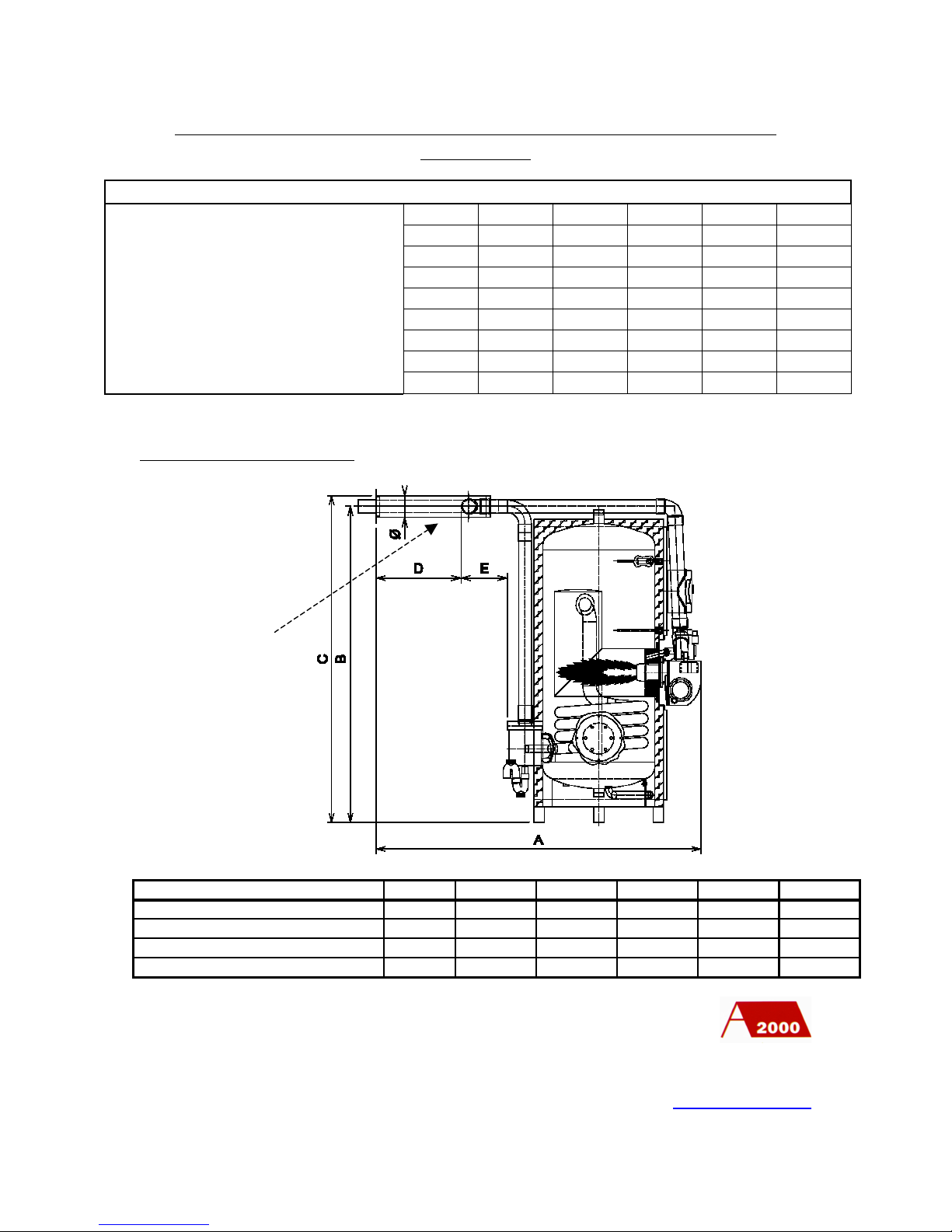
BALANCED FLUE AND CONVENTIONAL FLUE MAX’O GAZ
FEATURES
Standard Balanced Flue (variations are available, contact Atlantic 2000)
PO Box 11 Ashton Under Lyne OL6 7TR
+44. (0) 161 621 5960 Fax +44. (0) 161 621 5966
www.atlanticboilers.com
MODEL
ABCDEØ45/400
1885
1830
1900
470
290
125
55/700
2050
2170
2250
470
300
160
69/700
2050
2170
2250
470
300
160
69/1200
2255
2220
2300
470
300
160
MODEL
45/400
55/700
69/700
69/1200
90/1200
110/1200
Input
kW
46.4
56.1
70.5
70.5
91.8
112.2
Output
kW
45
55
69
69
90
110
Gas used
m3/hr
4.86
5.94
7.45
7.45
9.12
11.8
LPG used
m3/hr
1.88
2.3
2.88
2.88
3.76
4.6
Water content
ltr
390
720
720
1190
1190
1190
Volume recovery rate -10/60ºC-
mins
31
46
36
60
45
37
Litres continuous -10/60ºC-
ltr/hr
774
946
1187
1187
1548
1892
ltr/mins over 10 mins -10/60ºC-
ltr/mins
74
121
124
195
200
205
ltr/hr -10/60ºC- First hour from hot
ltr/hr
893
1310
2078
1901
2400
2394
Thru the wall piece
Page 7
7
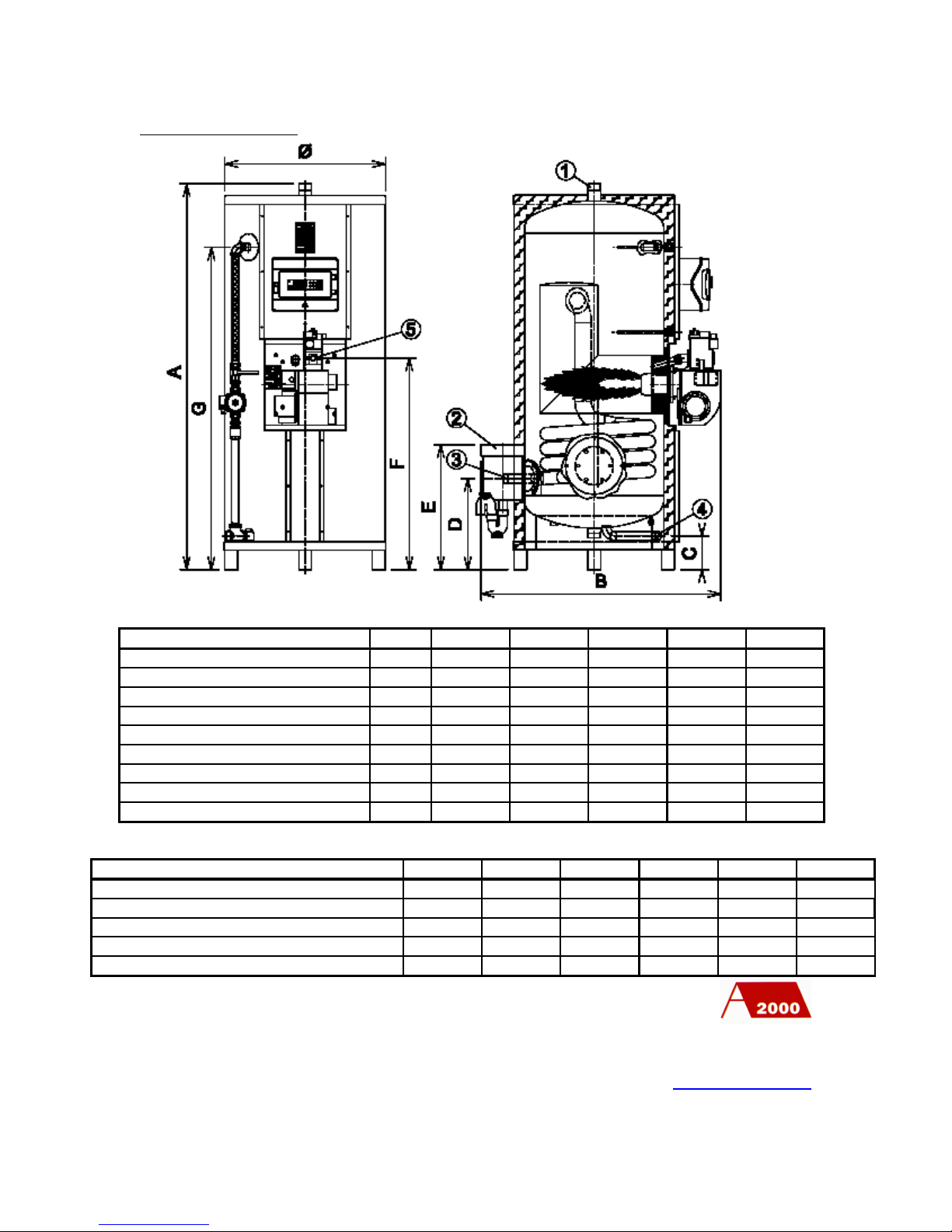
Conventional flue
CONNECTIONS
PO Box 11 Ashton Under Lyne OL6 7TR
+44. (0) 161 621 5960 Fax +44. (0) 161 621 5966
www.atlanticboilers.com
MODEL
45/400
55/700
69/700
69/1200
90/1200
110/1200
A
1810
2150
2150
2200
2200
2200
B
1125
1280
1280
1485
1485
1485
C
160
190
190
160
160
160 D430
490
490
500
500
500 E585
645
645
660
660
660 F965
1130
1130
1200
1200
1200
G
1515
1825
1825
1835
1835
1835
Ø
750
900
900
1100
1100
1100
Weight in kg
355
470
470
605
605
605
45/400
55/700
69/700
69/1200
90/1200
110/1200
*1* Hot water outlet
Ø
5050505050
50
*2* Flue outlet
Ø
200
200
200
200
200
200
*3* Cold water inlet
Ø
3250505050
50
*4* Drain point
Ø
3232323232
32
*5* Gas supply
Ø
2020202020
20
MODEL
Page 8

8
INSTALLATION OF THE MAX’O GAZ
MAX’O GAZ requires the installation of gas ( or LPG), water and electricity supplies which
must be provided by currently qualified installers. Relevant CE and BS requirements and local
regulation must be observed.
(Atlantic 2000 welcomes any queries at any time on 0161-621-5960)
1) LOCATION
MAX’O GAZ must be located on a hard standing and preferably a concrete base
extending at least 50mm beyond the unit on all sides
The most economic route should be selected for the evacuation of flue gases with
consideration for nuisance at the exit point from the building and for the trapped
drainage of condensate.
(See advice in the section on products of combustion).
Preferably, an access of 500mm should be allowed on the sides and rear of MAX’O
GAZ. Access at the front, to allow for burner withdrawal, should be 1500mm.
(Discuss restricted access with Atlantic 2000 on 0161-621-5960)
2) COLD WATER CONNECTION
Cold water supply should be connected to MAX’O GAZ in approved materials.
On a main cold water supply connection, an unvented kit is necessary and is offered
with the unit. This consists of a ball valve, a high capacity strainer, a pressure
regulating valve with manometer, a non return valve and one or two expansion vessels
fitted into the cold water supply line. In addition, a combined temperature/pressure
relief valve is supplied for fitting in the MAX’O GAZ storage vessel or DHW flow
outlet.
On a tank cold water supply connection, two ball valves and a high capacity strainer is
recommended.
On both types of connection, a mounting pack is recommended and will consist of a
pressure relief valve, a high capacity automatic air eliminator, an anti-vacuum plug and
a drain valve. The installation of unions is recommended to ease the cleaning of filters
and working equipment.
PO Box 11 Ashton Under Lyne OL6 7TR
+44. (0) 161 621 5960 Fax +44. (0) 161 621 5966
www.atlanticboilers.com
Page 9

9
3) DOMESTIC HOT WATER FLOW CONNECTION
Hot water supply should be connected to MAX’O GAZ in approved materials.
On the MAX’O GAZ hot water outlet of a mains cold water s ystem, the combined
temperature/pressure relief valve may be fitted. Then a full-bore tee should be installed
to take the high capacity automatic air eliminator with isolating ball valve.
These items should be isolated together with the MAX’O GAZ storage vessel and
fitted with a union to allow future access for maintenance.
On the MAX’O GAZ hot water outlet of a tank cold water system, a pressure relief
valve must be fitted. Then a full-bore tee should be installed to take an open vent pipe
leading over the cold water tank.
4) DOMESTIC HOT WATER RETURN CONNECTION
A hot water return connection is provided in the MAX’O GAZ. It must not be used as a
cold water inlet
In a hot water pumped circulation system, the return will include a ball valve, a strainer,
the pump, a non return valve, a ball valve and a thermometer; then a connection to the
MAX’O GAZ vessel with a union.
In a hot water system without circulation, a blending valve and thermometer should be
considered in an arrangement to mix the hot water flow with the cold water feed.
5) RELIEF VALVES
Do not connect pipework directly to the relief outlet. Leave an air gap leading to a
tundish, enabling relief water to be visually noted.
6) CONDENSATE DRAIN
MAX’O GAZ is a high efficiency condensing wate r heater. The condensing starts to
occur in the combustion gases as they pass down the vertical heat exchanger tubes, and
the condensate collects in the flue gases chamber and outlet. This must be drained away
to a gulley or drain using rigid PVC tube resistant to 60ºC temperature and running at a
slope 2-3º. Copper pipe should not be used,
PO Box 11 Ashton Under Lyne OL6 7TR
+44. (0) 161 621 5960 Fax +44. (0) 161 621 5966
www.atlanticboilers.com
Page 10

10
Additional condensing will occur in the flue exhaust system and this may be separately
drained through its own trap to the same gulley or drain. Normally, 20 mm or 32mm
PVC tube will carry the condensate flow.
IMPORTANT
Never fire the MAX’O GAZ burner without water in the water store.
Never fire the MAX’O GAZ without open cold and hot water connections.
Never plug off the relief valve outlets.
Never over-ride the control system, without knowledge.
For any further information you can contact Atlantic 2000 on
Technical 0161 621 5960
Commissioning 0161 621 5961
Servicing 0161 621 5961
Spares 0161 621 5962
PO Box 11 Ashton Under Lyne OL6 7TR
+44. (0) 161 621 5960 Fax +44. (0) 161 621 5966
www.atlanticboilers.com
Page 11
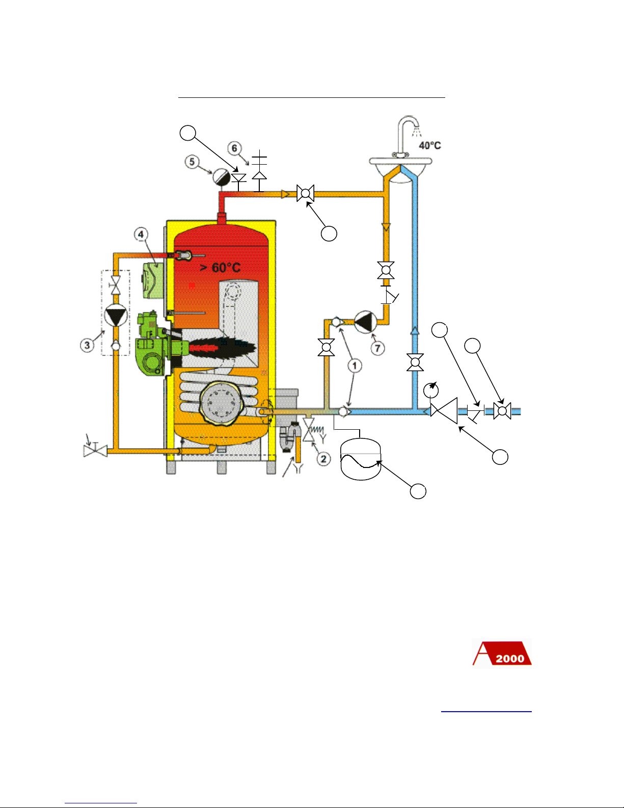
11
STANDARD PIPEWORK ARRANGEMENT
PO Box 11 Ashton Under Lyne OL6 7TR
+44. (0) 161 621 5960 Fax +44. (0) 161 621 5966
www.atlanticboilers.com
1 – Non return valve
2 – Pressure relief valve
3 – Anti-legionnella package
4 – Electric panel
5 – Automatic air vent
6 – Pressure and temperature relief valve
7 – Secondary circulating pump
8 – Anti vacuum plug
9 – Ball valve
10 – Strainer
11 – Pressure regulating valve
12 – Expansion vessel
Condensate
Cold water
8 1112
9
Drain point
Page 12
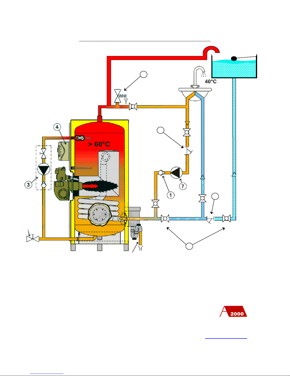
12
PIPEWORK ARRANGEMENT WITH A TANK
PO Box 11 Ashton Under Lyne OL6 7TR
+44. (0) 161 621 5960 Fax +44. (0) 161 621 5966
www.atlanticboilers.com
1 – Non return valve
2 – Pressure relief valve
3 – Anti-legionnella package
4 – Electric panel
5 – Ball valve
6 – Strainer
7 - Secondary circulating pump
Drain point
Condensate
Page 13
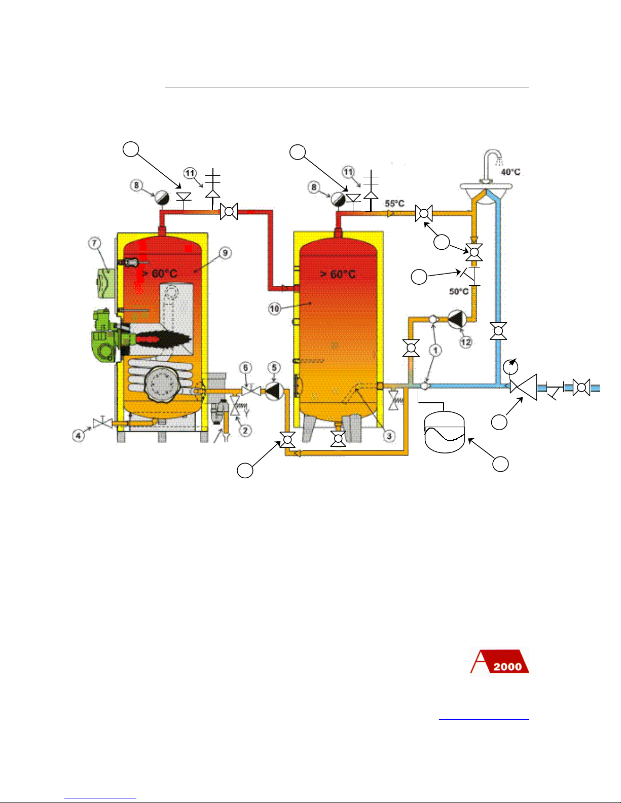
13
PIPEWORK ARRANGEMENT WITH A BUFFER STORAGE
PO Box 11 Ashton Under Lyne OL6 7TR
+44. (0) 161 621 5960 Fax +44. (0) 161 621 5966
www.atlanticboilers.com
1 – Non return valve
2 – Pressure relief valve
3 – Anti-sediment cold water inlet
4 – Entire drain
5 –Pump
6 – Hot water transfer valve
7 – Electric panel
8 – Automatic air vent
9 – MAX’O GAZ
10 – Buffer storage
11 –Pressure and temperature relief valve
12 – Secondary circulating pump
13 – Anti vacuum plug
14 – Ball Valve
15 – Strainer
16 – Expansion vessel
17 – Pressure regulating valve
Cold water
Condensates
131417
Page 14
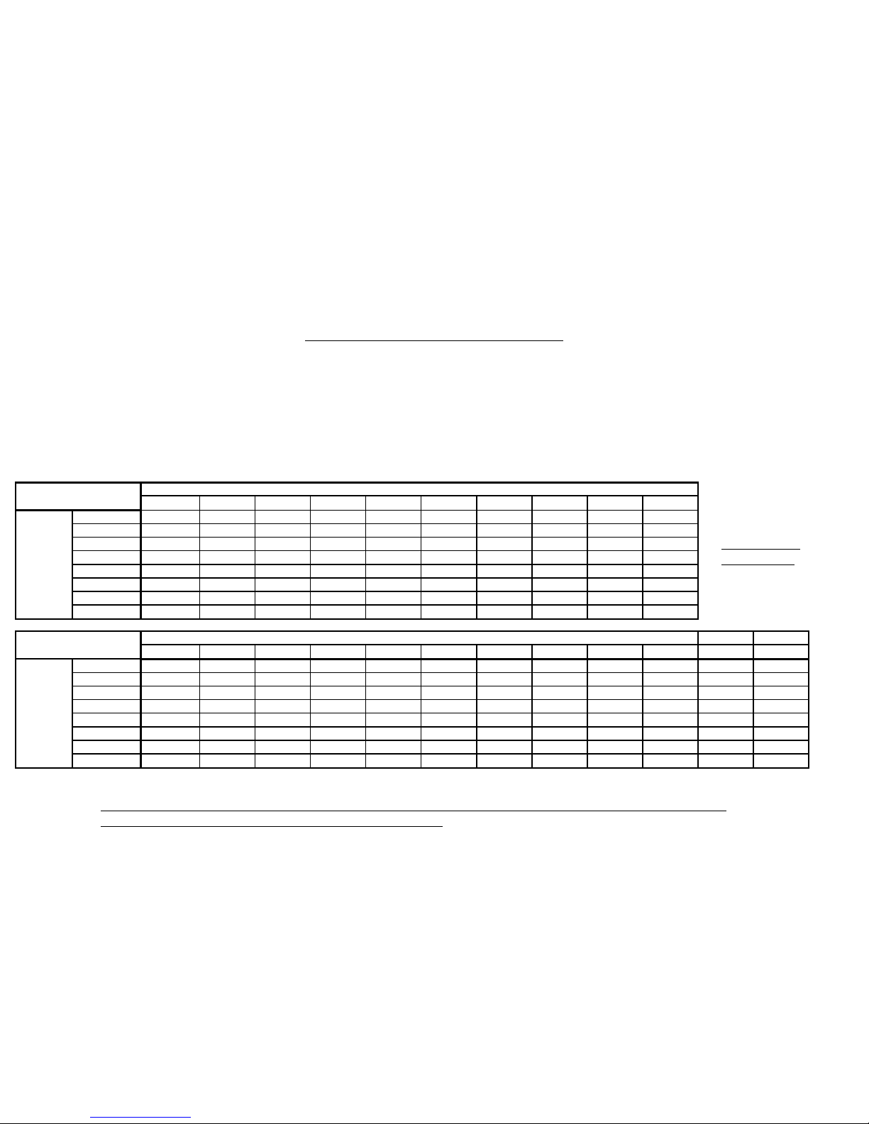
14
3691215202530405020
9.7
6.625181210
8.5
7.53239272118161412119.2
8.140594032272421181614
12501107661524639343126
2365220
150
120
10092797063544780340
230
190
160
140
120
1109783
73
100
690
470
380
330
290
250
220
200
170
150
Length of pipe (metres)
Nominal
size (mm)
Discharge (m³/h)
102030405060708090
100
125
150
3/4
340
2301640
440
350
1¼
1400
930
740
630
560
500
460
430
400
3801½2100
1400
1100
960
850
760
700
650
610
570
510
46023900
2600
2100
1800
1600
1400
1300
1200
1100
1000
960
8602½7700
5300
4300
3600
3200
2900
2700
2500
2300
2200
1900
1800312000
8200
6600
5600
5000
4500
4100
3800
3600
3400
3000
2700424000
1700
1300
11000
10000
9200
8400
7800
7300
6900
6100
5500
Discharge (FT³/h)
Length of pipe (feet)
Nominal
size (ins)
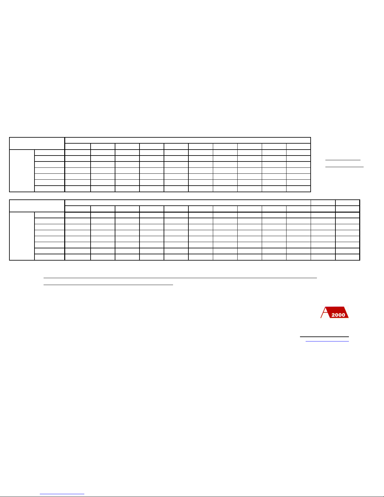
THE GAS PIPEWORK CONNECTIONS
The size of the gas pipework to the boilers should be chosen to ensure the necessary minimum pressure for the nominal required flow
rate at the upstream entry point of the gas train.
The diameter of the pipe lines will be calculated as a function of the allowed pressure drop, the length of the pipework distribution &
the number of fittings in the distribution.
There are a number of ways of carrying out these calculations and the attached is based on C.P. 331 1974.
Discharge in a straight horizontal steel pipe (to table 2, medium, of BS 1387:1967) with 1m.bar 0.4 in w.g. differential
pressure between the ends, for gas of relative density 0.6 (air=1)
GAS FLOW IN
STEEL TUBE
Page 15
15
369121520253040
50
22
8.7
5.82818129.487
5.9353222171513119.5
8.5
7.2
6.342543729252218161512
11541107560514538333026
2376280
190
150
130
12098867866
58
108
750
510
410
350
310
260
230
210
180
160
Nominal
size (mm)
Discharge (m³/h)
Length of pipe (metres)
102030405060708090
100
125
150
3/4
630
420
34011100
740
580
500
440
390
360
1¼
1800
1200
950
810
710
640
590
540
510
480
420
3801½3900
2600
2100
1800
1600
1400
1300
1200
1100
1000
930
83027000
4800
3800
3200
2800
2600
2300
2200
2000
1900
1700
15002½11000
7700
6200
5200
4600
4200
3800
3500
3300
3100
2800
2500317000
12000
9400
8000
7100
6400
5800
5400
5100
4800
4200
3800425000
17000
13000
11000
10000
9100
8400
7800
7300
6900
6100
5500
Discharge (FT³/h)
Length of pipe (feet)
Nominal
size (ins)
PO Box 11 Ashton Under Lyne OL6 7TR
+44. (0) 161 621 5960 Fax +44. (0) 161 621 5966
www.atlanticboilers.com
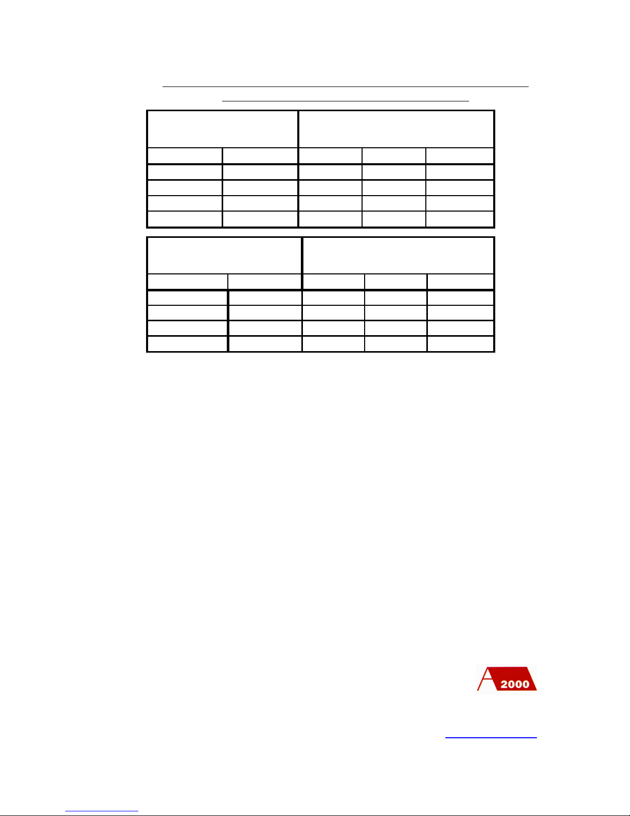
Discharge in a straight horizontal copper tube (to table of BS 659:1967) with 1m.bar 0.4 in w.g. differential pressure
between the ends, for gas of relative density 0.6 (air=1)
GAS FLOW IN
COPPER TUBE
Page 16
16
Mild Steel
Copper
Elbows
Tees
90º Bends
up to 25
up to 28
0.5
0.5
0.3
32 top 40
35 to 42
110.3
50
54
1.5
1.5
0.5
80
76.1
2.5
2.5
1
Nominal size (mm)
Appropriate additional lenghts
to be allowed (m)
Mild Steel
Copper
Elbows
Tees
90º Bends
up to 1
up to 1
221
1 ¼ to 1 ½
1 ¼ to 1 ½
331
2
2
552
3
3
883
Nominal size (ins)
Appropriate additional lenghts
to be allowed (ft)
The effects of elbows, tees or bends inserted in a run of pipe (expressed as
the approximate additional lengths to be allowed)
To make use of the tables on pages 14 and 15 the run of gas pipework from the meter to
the water heater must first be decided. Then, the length of the run (or the longest run
when more than one water heater is installed) is measured together with the numbers of
elbows and/or bends and tees counted.
The gas flow requirements of the water heaters are taken from the table on page 6. The
pipe size of the run, or the main part of the run for several water heaters, is assessed from
the tables on pages 14 and 15.
The effect of the fittings is then taken, from that pipe size, out of the tables on page…
The whole run is the re-checked for this size to ensure the overall pressure drop from the
meter to the water heater is within the prescribed limit. If several water heaters are
involved, the prescribed limit is proportioned over the different lengths of pipe with
different flow rates.
If you have any queries concerning the gas pipe work,
call Atlantic 2000 on 0161 621 5960
PO Box 11 Ashton Under Lyne OL6 7TR
+44. (0) 161 621 5960 Fax +44. (0) 161 621 5966
www.atlanticboilers.com
Page 17
17
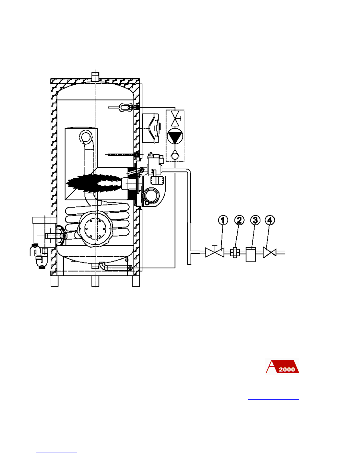
MAX’O GAZ GAS SUPPLY FROM A PRESSURE
REGULATING VALVE
PO Box 11 Ashton Under Lyne OL6 7TR
+44. (0) 161 621 5960 Fax +44. (0) 161 621 5966
www.atlanticboilers.com
1 –Pressure regulating valve
2 – Union brass
3 – Filter
4 – Gas valve
Page 18
18
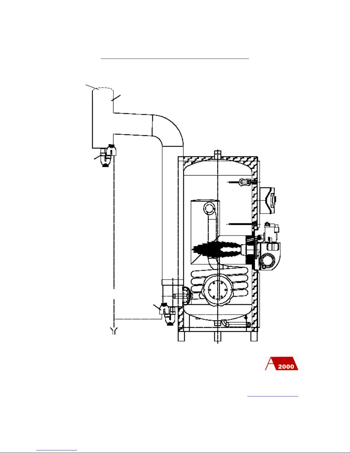
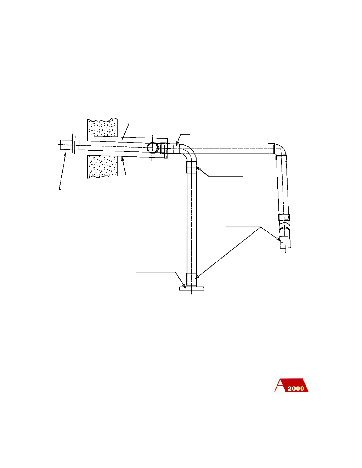
CONVENTIONAL FLUE ARRANGEMENT
Flue made from high grade plastic or austenitic stainless steel
PO Box 11 Ashton Under Lyne OL6 7TR
+44. (0) 161 621 5960 Fax +44. (0) 161 621 5966
www.atlanticboilers.com
Stack
Condensate outlet
at base of vertical
stack
Condensate outlet
Drain or lift Pump
Slope/ 3%
Bull nose 25 mm
mesh terminal
(cowls not to be
fitted)
Page 19
19
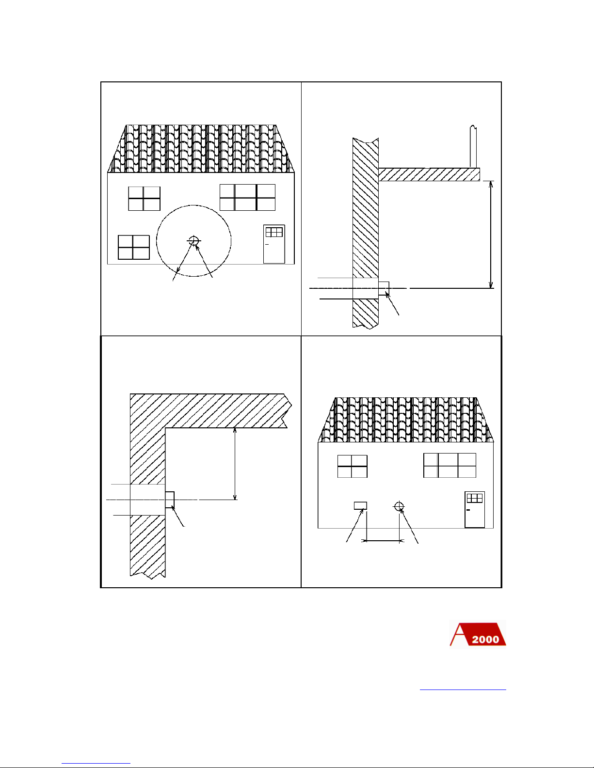
BALANCED FLUE CONNECTIONS ON WALL OUTLET
Flue made from high grade plastic or austenitic stainless steel
IMPORTANT:
All the plastic connections must be air & gas tight
PO Box 11 Ashton Under Lyne OL6 7TR
+44. (0) 161 621 5960 Fax +44. (0) 161 621 5966
www.atlanticboilers.com
Slope/3%
Balanced flue outlet
Concentric balanced flue
Stainless steel union
Stainless steel union
Stainless steel union
Flue Outlet
Page 20
20
PO Box 11 Ashton Under Lyne OL6 7TR
+44. (0) 161 621 5960 Fax +44. (0) 161 621 5966
www.atlanticboilers.com
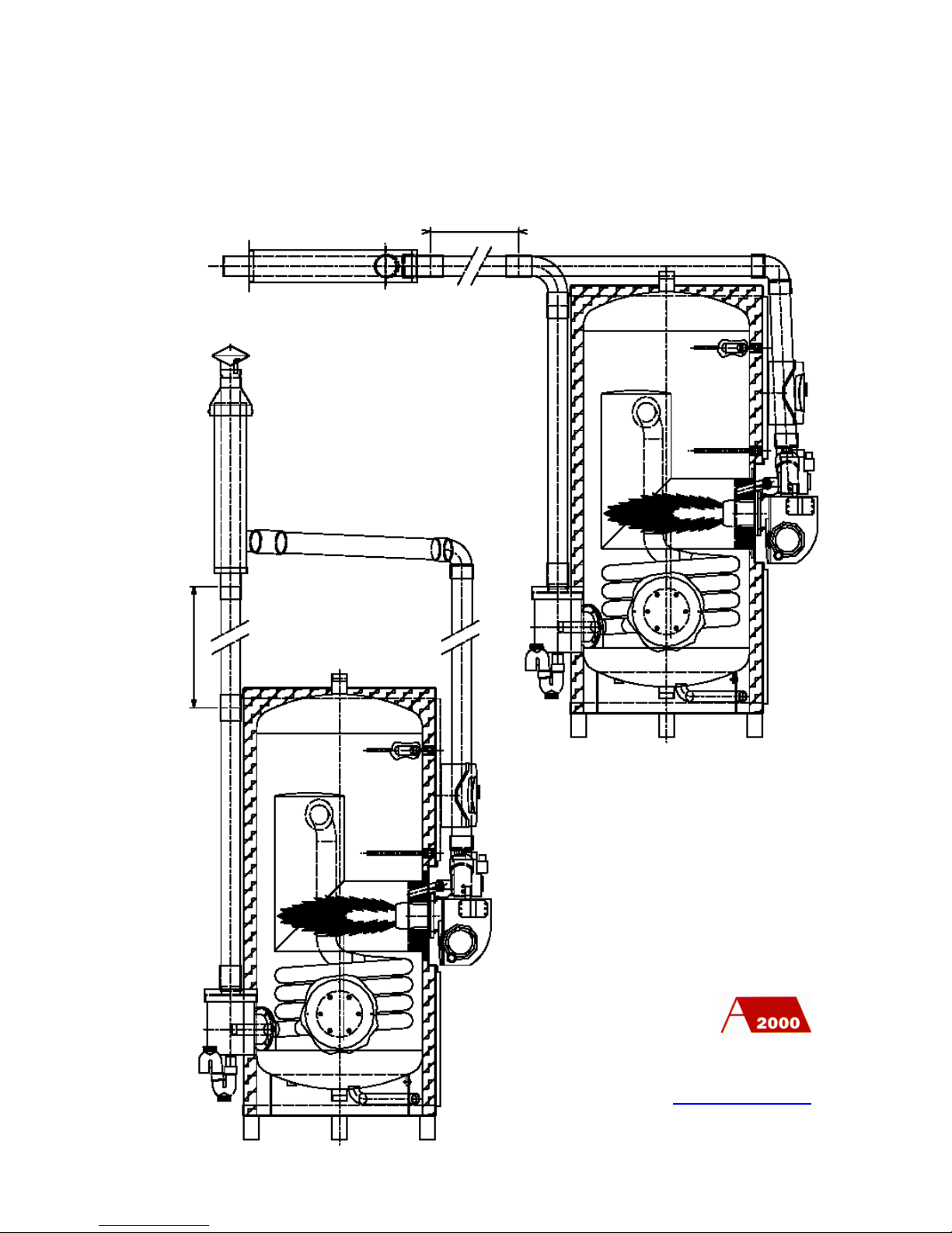
Balanced flue outlet
R = 4m
Balanced flue outlet
Balanced flue outlet
Balanced flue outlet
Air inlet for
ventilation
purposes
Fitting of the balanced flue outlet on a
façade with windows or doors
Fitting of the balanced flue outlet under a
balcony or a roof
BALCONY
Fitting of the balanced flue outlet in a wall
angle
Fitting of the balanced flue outlet on a
façade with air inlet
R=4000 mm
1500 mm
2500 mm
2000 mm
Page 21
21
PO Box 11 Ashton Under Lyne OL6 7TR
+44. (0) 161 621 5960 Fax +44. (0) 161 621 5966
www.atlanticboilers.com
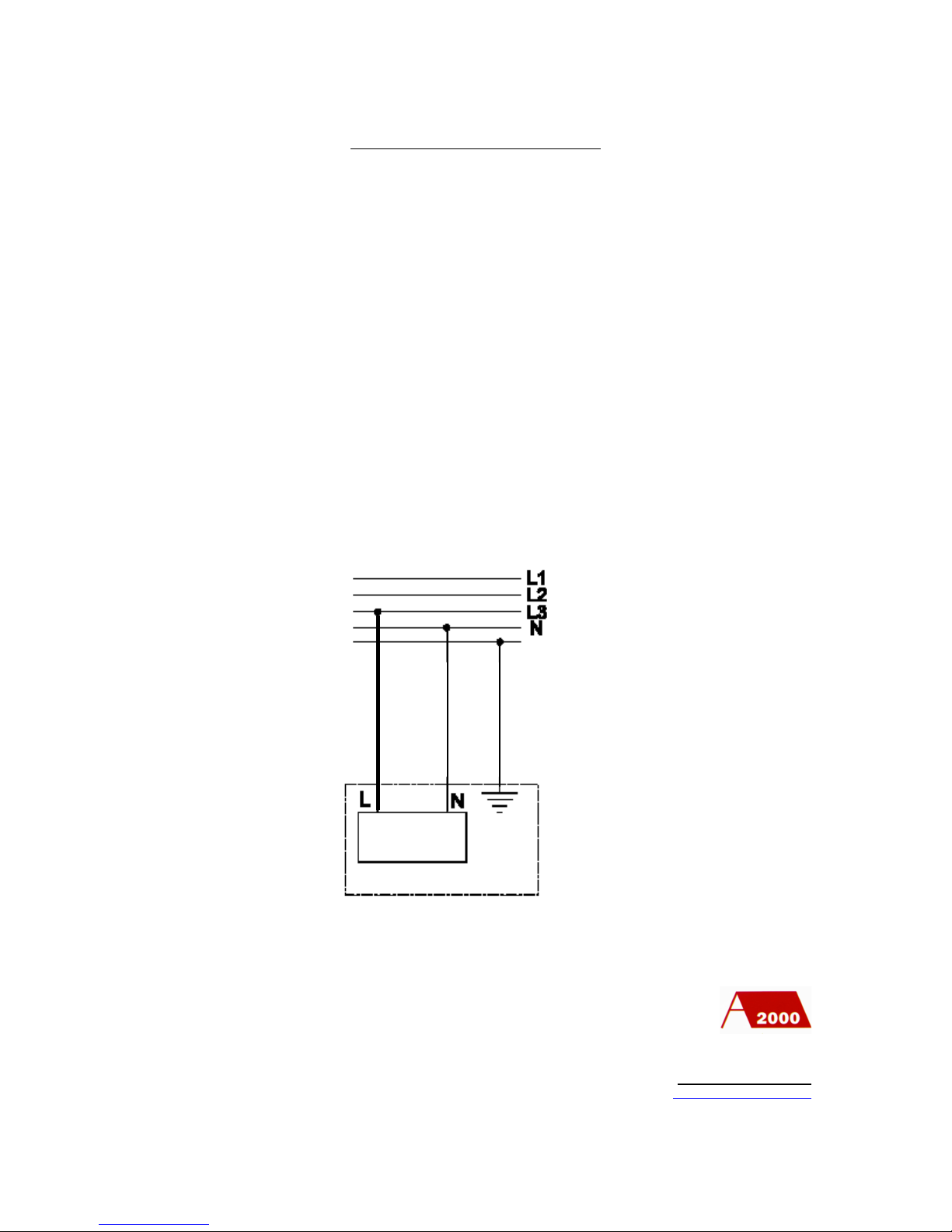
VERTICAL BALANCED FLUE
HORIZONTAL BALANCED FLUE
Dimension to be
determined:
Normally
4000 mm Maximum
(If longer, consult
Atlantic)
Dimension to be determined:
Normally
4000 mm Maximum
(If longer, consult Atlantic)
Page 22
22
E
E
ELECTRIC CONNECTION
- MAX’O GAZ are entirely wired in the f actory
- The voltage supply should be single current 230 volts/50 Hz with live,
neutral and earth
- When the electric MAX’O GAZ supply is three phase 415 volts/50 Hz, a
single phase is selected
- The isolator switch will be fixed as close as possible to the water heater.
- Before turning the electricity supply on, make sure that it is a 230 volts
single phase current.
- Finally close the control panel before operation.
PO Box 11 Ashton Under Lyne OL6 7TR
+44. (0) 161 621 5960 Fax +44. (0) 161 621 5966
www.atlanticboilers.com
Circuit
breaker 4A
Page 23
23
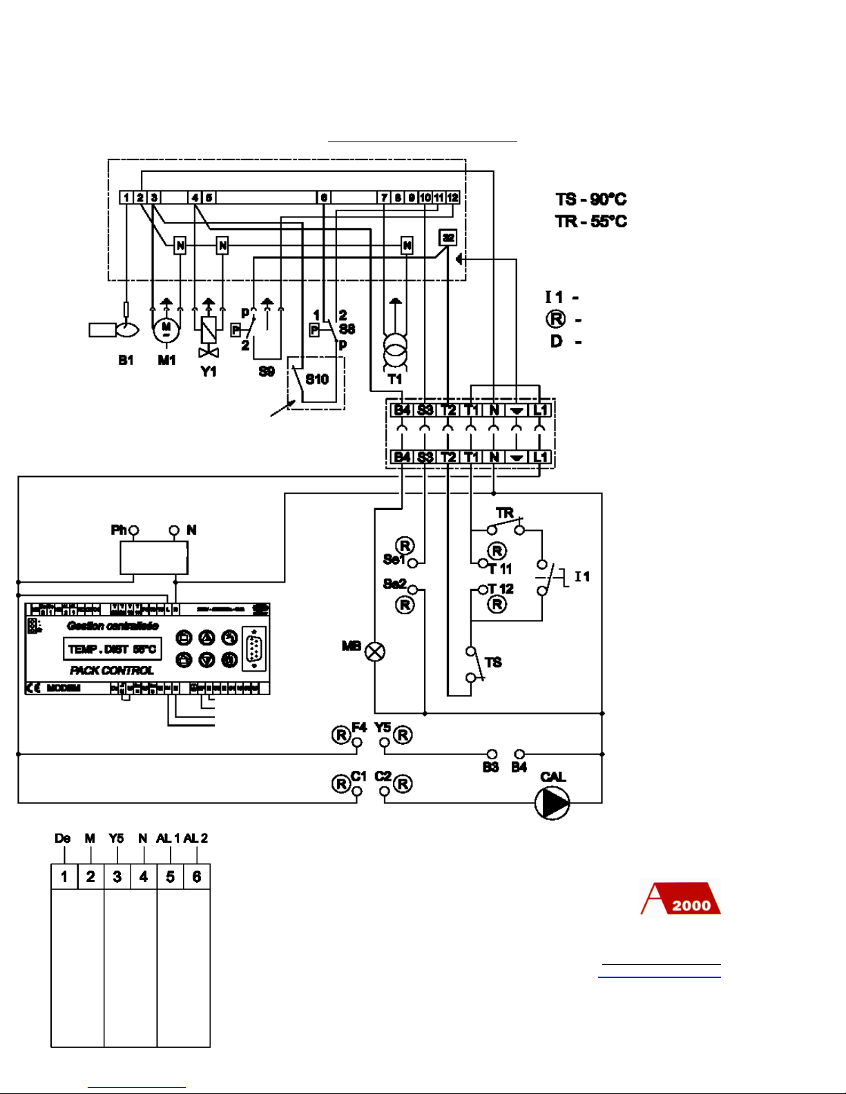
ELECTRIC DIAGRAM
PO Box 11 Ashton Under Lyne OL6 7TR
+44. (0) 161 621 5960 Fax +44. (0) 161 621 5966
www.atlanticboilers.com
- B1 Spark electrode
- M1 Fan motor
- Y1 Gas valve
- S9 Gas pressure switch
- S10 flue pressure switch
- S8 Air pressure switch
- T1 Ignition transformer
- MB burner run lamp
- TS High limit thermostat
- TR Safety regulation
thermostat
- CAL legionella pump
Control Box
For balanced flue only
Burner
terminals
Circuit
breaker 4A
Shunt
Immersion sensor S1
Watching sensor SP
Inter / normal / emergency
Pack Control connection
Circuit breaker
FAULT ALARM
(low voltage, 2-5 amp,
50-60 Hz)
RUN SIGNAL
Page 24
24
SETTINGS
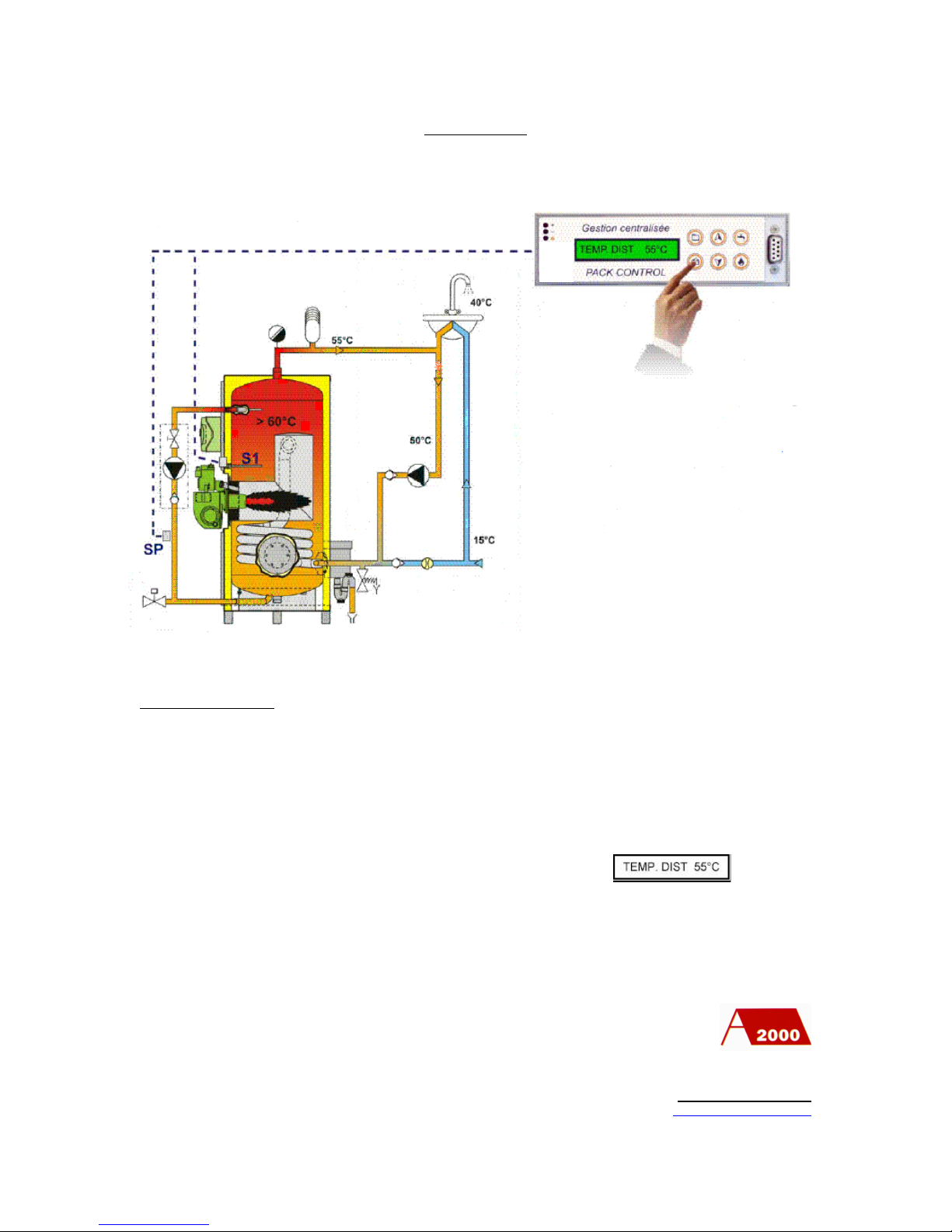
Start procedure
First, fix the SP sensor at the right place (as shown on the scheme), check the anti-
legionnella pump wiring, than turn the power on using the main circuit breaker.
As soon as you turn the power on, the Pack Control screen switch on, the default lamp
flashes once and the default display show after a few seconds:
PO Box 11 Ashton Under Lyne OL6 7TR
+44. (0) 161 621 5960 Fax +44. (0) 161 621 5966
www.atlanticboilers.com
Page 25
25
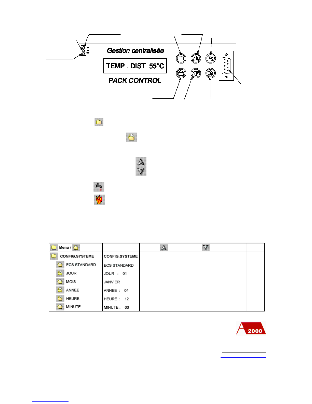
- The key is used to reach the different menus
- In each menu, the key is used to reach the different sub menu
- For the settings, use the following keys:
- The key is not used in the case of a gas generator
- The key is used for a manual activation of the anti-legionnella cycle.
1) Preliminary operation before use
Date and time settings
PO Box 11 Ashton Under Lyne OL6 7TR
+44. (0) 161 621 5960 Fax +44. (0) 161 621 5966
www.atlanticboilers.com
Closing lamp
3 port valve
Default lamp
Opening lamp
3 port valve
Settings:
yes or +
Settings:
no or -
Day restart
Anti-legionella
Computer RS 232 plug
Screen display
Detailed menu
Settings
To increase
To decrease
Show the Pack control configuration sets in the factory
Day settings
Month settings
Year settings
Hour settings
Minute settings
to activate (YES (oui) ) or increase
to deactivate (NO (non) ) or decrease
Page 26
26
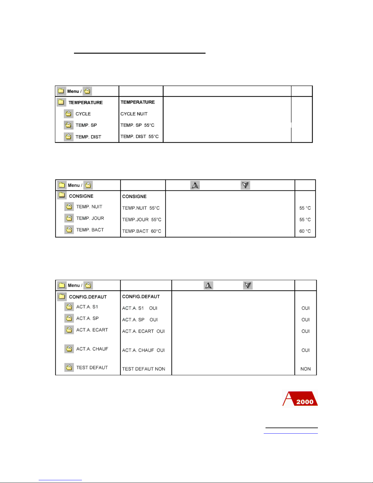
Screen display
Detail
Show the current cycle, day (jour) or night (nuit)
Show the temperature on SP thermostat (anti-legionella sensor)
Show the temperature on S1 thermostat (water heater sensor)
Screen display
Settings
To increase
To decrease
Factory
settings
Water temperature setting
Unuseful with MAX’O GAZ
Anti-legionella temperature setting
Screen display
Settings
To increase
To decrease
Activate or deactivate the alarm on S1 sensor
Activate or deactivate the alarm on SP sensor
Activate or deactivate the alarm on SP sensor after an antileginnella cycle (When TEMP.BACT has not been reached)
Allow a manual default test
Activate or deactivate the alarm on S1 sensor after an antileginnella cycle (When TEMP.BACT has not been reached at
the end of the heater time defined later)
Factory
settings
2) Exploiter settings (authorization 1)
Temperature display
Temperature settings
Configuration defaults
PO Box 11 Ashton Under Lyne OL6 7TR
+44. (0) 161 621 5960 Fax +44. (0) 161 621 5966
www.atlanticboilers.com
Page 27
27
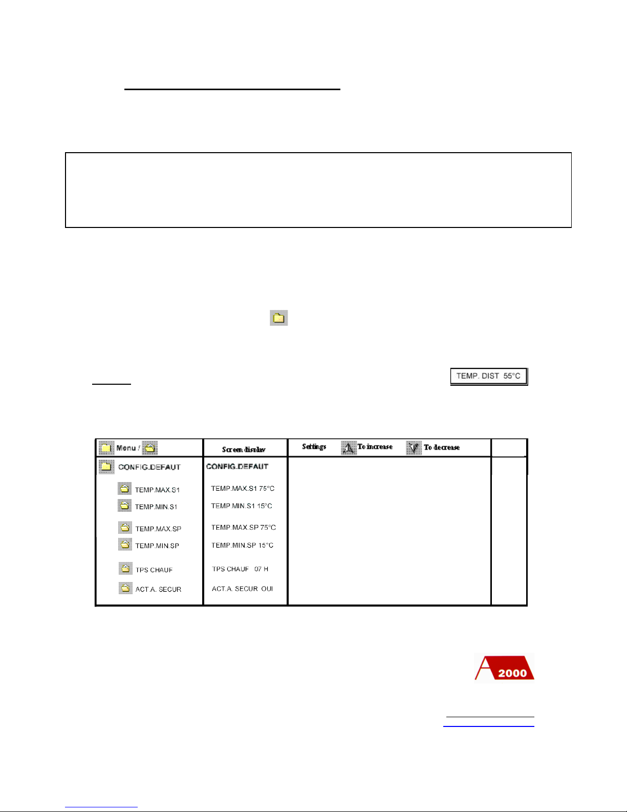
3) Installer settings (authorization 2)
WARNING
To reach the authorization 2 sub menus:
-Turn the 230V Pack Control power off
-Whilst pressing the key, turn the power on and remain pressing for
15 s
NOTE:
After 1 minute of inactivity, the default display appears
After 10 minutes of inactivity, the authorization 2 mode is inactive.
PO Box 11 Ashton Under Lyne OL6 7TR
+44. (0) 161 621 5960 Fax +44. (0) 161 621 5966
www.atlanticboilers.com
The following settings have to be done by competent personnel
Wrong settings can generate failures in the installation and a dangerous increase of
temperatures with risks of scalding
Set the maximum alarm temperature on sensor S1
Set the minimum alarm temperature on sensor S1
Set the maximum alarm temperature on sensor SP
Set the minimum alarm temperature on sensor SP
Set the maximum length of the anti-legionella cycle
Switch on/off the burner lock out alarm
Factory
settings
75º C
15º C
75º C
15º C
07 H
OUI
Page 28

28
CHECKINGS BEFORE STARTING THE WATER HEATER
Check that:
- the MAX’O GAZ is supplied with the appropriate gas, with which it is set
to fire
- the gas pressure corresponds to the setting marked on the heater
- the water heater is full of water
- the safety valve is correctly installed
- an automatic air vent is installed on the highest point
- nothing blocks the evacuation of the combustion gases
- the boiler plant has proper ventilation ( for a conventional flue use, high
and low ventilation needed)
- the supply voltage is the correct one for the water heater (single phase
230V 50Hz + earth)
- neutral and phase are correctly connected
- earth is correctly connected
-230 volts between phase and earth
-0 volts between neutral and earth
- the gas line has been correctly tested for soundness
- all the connections are air or gas tight
- condensate drain is connected
- anti-legionnella pump has been installed
PO Box 11 Ashton Under Lyne OL6 7TR
+44. (0) 161 621 5960 Fax +44. (0) 161 621 5966
www.atlanticboilers.com
Page 29

29
STARTING THE WATER HEATER
Procedure:
1) Check that the switch inside the water heater is on “0-OFF” (Pack Control
switched off)
2) Close the water heater drain valve
3) Open the cold water supply valve
4) Open the hot water outlet valve
5) Open the nearest hot outlet water
6) As soon as there is no air in the water system, close the outlet (5)
7) The water heater is under the correct system pressure
8) Purge the gas line
a. close the water heater gas valve
b. open the water heater gas valve
c. while doing this, check the gas supply pressure with a water manometer
d. when all the air has come out of the line
e. close the water heater gas valve
f. close the screw
9) Open the water heater gas valve
10) Check the screw gastight
11) Nothing blocks the flue
12) Check that all the pipe is pressure tested
13) The supply voltage is the correct one for the water heater (single phase 230 V
50Hz + earth)
14) Turn the water heater switch on “1-ON”
a. the Pack Control switch on
b. the Pack Control ignition allows the burner to start
c. the fan starts and pre-purged the combustion chamber
d. after thirty seconds the burner will fire
PO Box 11 Ashton Under Lyne OL6 7TR
+44. (0) 161 621 5960 Fax +44. (0) 161 621 5966
www.atlanticboilers.com
Page 30

30
During the first starting, the burner may switch to safety position
because of any air remaining in the line.
SAFETY CHECKINGS
- Close the gas supply, the burner gas valve should close almost
instantly and the burner will stop without moving onto the lock-out
position
- Open the gas supply again, a new cycle will occur: ventilation of the
combustion chamber, ignition, and gas valve opening.
- Unplugging the ionization probe, the gas valve will close within 5
seconds, a new starting cycle occurs: ventilation, ignition, valve
opening, then the burner switches to the lock-out position.
15) While the burner is working, check the Pack Control temperature
a. If the temperature is different than the one required, adjust it
16) During the first fire, check that all the elements of control and safety are
working correctly
17) Do a combustion analysis and if needed, adjust the burner setting
18) After the first start and stop of the burner, check that all the pipe work remains
air and gas tight
19) The anti-legionnella pump will start when the hot water temperature is 10ºC
below the control temperature
PRECAUTION TO PREVENT FROST
Switching off the water heater
1) Switch the electricity supply off
2) Close the gas valve
3) Close the Max’o gaz water supply valve
4) Open the water heater drain valve
5) Open the hot water outlet valve
6) Open the most convenient drain outlet
PO Box 11 Ashton Under Lyne OL6 7TR
+44. (0) 161 621 5960 Fax +44. (0) 161 621 5966
www.atlanticboilers.com
Page 31
31
THE COMMISSIONING OF THE MAX’O GAZ
All Atlantic boilers and water heaters are thoroughly tested for mechanical, electrical and
combustion performance at the factory. The combustion performance tests are based on
gas equivalent to the North Sea natural gas provided by British Gas and at low pressures
normally supplied. The test takes up to two hours and the results are recorded.
The prime object of the site commissioning of the water heater(s) is, subject to installed
conditions, to match the optimum combustion performance results reached at the factory
and to ensure the water heater(s) is/are installed according to the conditions of guarantee.
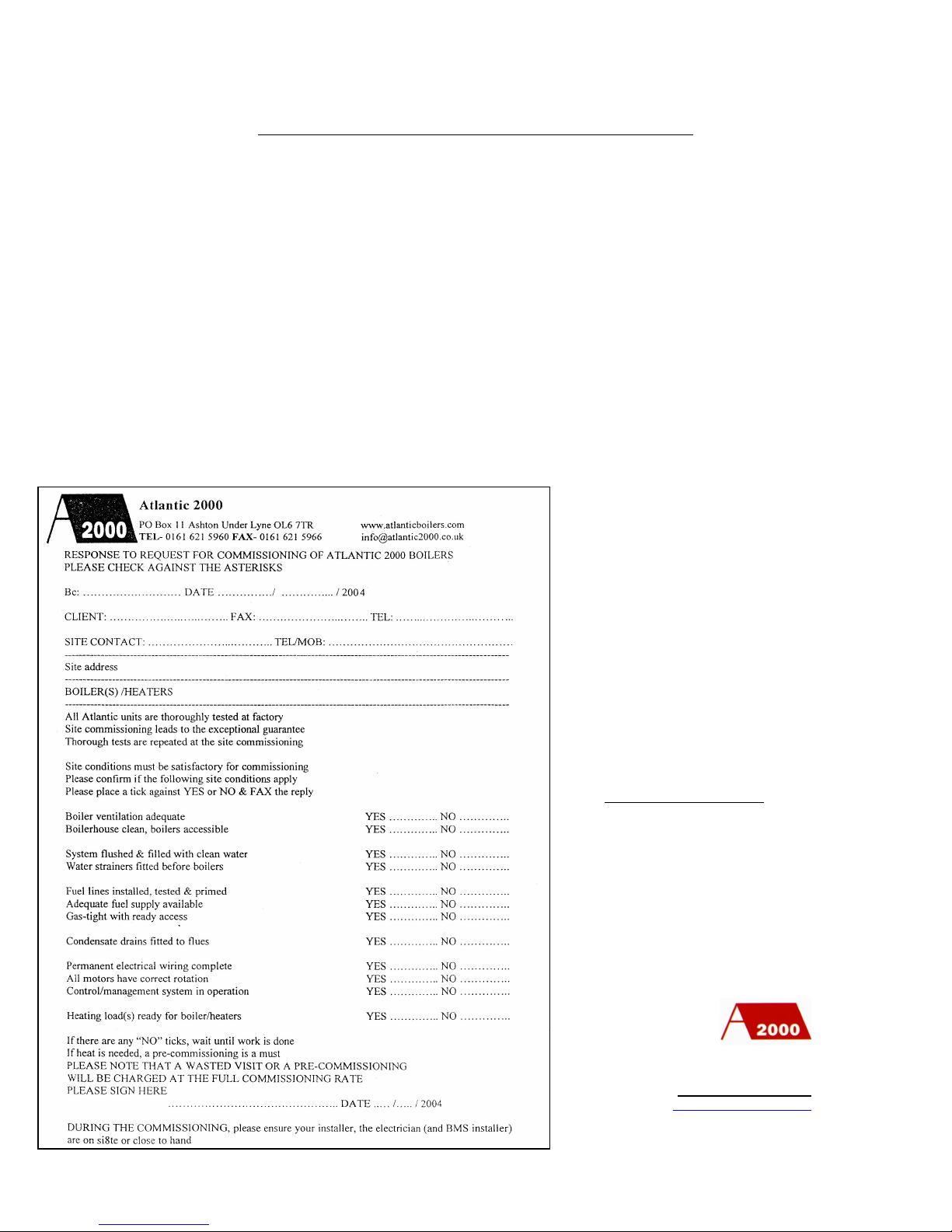
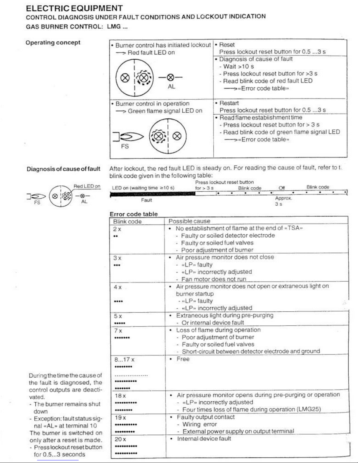
The following check list should be satisfied before the commissioning takes place. To
arrange the commissioning Atlantic should be given a minimum of ten days notice of the
date and time required.
PO Box 11 Ashton Under Lyne OL6 7TR
+44. (0) 161 621 5960 Fax +44. (0) 161 621 5966
www.atlanticboilers.com
Commissioning sheet
Page 32
32
Page 33
33
PO Box 11 Ashton Under Lyne OL6 7TR
+44. (0) 161 621 5960 Fax +44. (0) 161 621 5966
www.atlanticboilers.com
Page 34

34
DEFAUTL FINDING CHART
INDICATION
LIKELY CAUSE
POSSIBLY REMEDY
The burner does not start and no
lamp is shining
-The switch is on the wrong position
-No electricity supply
-Faulty fuses
-Defective connections
-Switch on the water heater
-Check the electricity supply
-Change the fuse
-Check the connections
The Pack Control is switched on
but the fan does not start
-Burner/gas valve connection non
plugged
-No gas
-Gas pressure too low
-Defective Pack Control
-Plug the connection
-Open the gas valve
-Check pressostat connections
-Check gas pressure upstream of the
gas valve
-Check the aquastats
-Check the voltage attendance
between T2 and neutral
-Switch the key in the safety position
to use the additional adjustable
thermostat
Recur of the starting procedure
-Fall of the supply water heater
voltage
-Check the supply water heater
voltage
The fan engine start, but goes to
lock out before the pre-ventilation
-The air pressostat contact remain in
the wrong position (air intendance
when the burner stop)
-Check and set the pressostat again
-Change the pressostat
The fan engine start but goes to
lock out after the pre-ventilation
without any burner start
-High tension wire cut
-High tension wire loosened
-Dirty spark electrode
-Wrong start electrode setting
-Default in start electrode insulation
-Defective start converter
-The gas valve does not open
-Check the connections
-Change the high tension cable
-Clean
-Set it again
-Change the electrode
-Replace
-Check the gas valve
PO Box 11 Ashton Under Lyne OL6 7TR
+44. (0) 161 621 5960 Fax +44. (0) 161 621 5966
www.atlanticboilers.com
Page 35

35
INDICATION
LIKELY CAUSE
POSSIBLY REMEDY
Goes to lock out after the start of
the burner
-Wrong position of the neutral
-Low voltage
-Wrong connection to the earth
-Ionization current too low
-The gas valve does not open
-Flame lift-off
-The flue is closed up
-Wrong Air manostat settings
-Check the electricity supply
-Check the starting voltage
-Check the connections
-Check the ionization electrode
-Check the gas valve
-Set the burner again
-Unblock the flue
-Set it again
After the start, the burner goes to
lock out
-Gas pressure too high
- Wrong soft start settings
-Set it again
Stop of the burner then start again
without going to lock out
-Dirty filter
-Discharges too important on the gas
line
-Clean the filter
-Set the combustion again
-Change the gas line
Limit thermostat has worked
-Anti-legionnella pump did not start
-Pack control set temperature too high
-Defective thermostat
-Check the pump
-Set the temperature again
-Change the thermostat
PO Box 11 Ashton Under Lyne OL6 7TR
+44. (0) 161 621 5960 Fax +44. (0) 161 621 5966
www.atlanticboilers.com
Page 36

36
THE GUARANTEE ON THE MAX’O GAZ
This guarantee is to the purchaser of the water heater(s) who is deemed to be the installer.
If the water heater(s) is (are) purchased by the eventual user who then arranges to install
the water heater(s), the eventual user is deemed to be the installer. The details of the
guarantee are given to assist the installer in obtaining effective action within the
guarantee and they are in addition to the installer’s legal rights under the relevant
statutory enactments for the time being in force in England, Wales, and Scotland.
Gas or electrical equipment:
The replacement or repair of the item, including the cost of its delivery to the site of the
installation or its equal within England, Wales and Scotland, provided that the defect or flaw
occurs within 2 calendar years of the commissioning date.
Removable component of the water heater assembly (other than the gas or electrical equipment)
The replacement or repair of the item, including the cost of its delivery to the site of the
installation or its equal within England Wales and Scotland if the defect or flaw occurs within 2
calendar years of the commissioning date.
The main body of the water heater.
The repair of any welding defects in the main body of the water heater including any necessary
removal or replacement of that part of the water heater on site if the defect occurs within 3
calendar years of the commissioning date.
Definitions:
The effective actions stipulated in this guarantee are subject to the purchaser complying
completely with the following:
1) The water heaters are installed according to the recommendations of this technical
booklet, the recommended codes of practice of the C.I.B.S. and the B.S.I., and the
checklist on page 31 is satisfied.
2) The commissioning of the water heaters by ACM Atlantic and their regular annual
servicing and maintenance.
3) The payment in full, by the purchaser unless otherwise agreed, of the invoice for the
supply and delivery of the water heater(s) to site, any other relevant invoices connected
with the water heater positioning and fixing, and the invoices for commissioning and any
correction of installation error, all to be made within one calendar month of the date of
the invoice.
4) The presentation, at the time of a claim under the guarantee, of the water heater
registration number, the commissioning record with date , and the necessary information
for defining any replacement part.
5) When a replacement item is supplied for a defective item, the defective item must be
returned to ACM Atlantic at their registered office within 6 weeks of the date of
notification of the defect carefully labeled with registration number of the water heater
and the name and the order reference of the purchaser of the water heater. If this is not
complied with, the purchaser will be charged with the cost of the item and its delivery.
 Loading...