

Page 1
CHARNWOODOLX
OilFired
HearthBoiler
Operating
and
InstallationInstructions
BishopsWay,Newport,IsleofWight,PO305WS
Tel:+44(0)1983537799 Fax: +44(0)1983537788
E-Mail: charnwood@ajwells.co.uk Internet:www.charnwood.com
Page 2

Page 3

CHARNWOODOLX45
OperatingandInstallationInstructions
OperatingInstructions
GeneralPoints........................................................4
Fuel..........................................................................4
ControllingTheBoiler............................................4
ElectricFlameEffectandFanHeater......................4
IfTheBurnerFailstoLight......................................4
Maintenance............................................................4
ReplacingtheFlameEffectBulb...............................4
InstallationInstructions
Health&SafetyPrecautions....................................6
Standards&Regulations..........................................6
Performance...........................................................6
AirSupply...............................................................6
Chimney..................................................................6
Hearth&FireSurround..........................................8
OilSupply................................................................8
PreparationoftheFireplace....................................9
CentralHeatingSystem...........................................9
FittingTheFire.......................................................10
ElectricalConnection..............................................10
CombustionChamberAssembly............................10
FinishingTheInstallation.........................................11
Commissioning.......................................................12
OverallDimensions................................................12
Specifications..........................................................14
WiringDiagram......................................................15
ElectrodeSettings...................................................16
ExplodedPartsDrawing-Boiler.............................17
ExplodedPartsDrawing-Burner...........................18
BishopsWay,Newport,IsleofWight,PO305WS
TechnicalSupportTel: +44(0)1983537799 Fax: +44(0)1983537788
E-Mail: charnwood@ajwells.co.uk Internet: www.charnwood.com
Page3
OLXV5.205.04
Page 4
CharnwoodOLXOilFiredHearthBoiler
OperatingInstructions
GENERALPOINTS
Beforeusingtheboilerforthefirsttime,checkwiththe
installerthatithasbeencorrectlyinstalledand
commissioned.Donotattempttousetheboilerbefore
ithasbeencommissioned.
FUEL
Theboilerissetuptoburn28sec.viscosityoil,thisis
commonlyknownasKerosene.DonotuseGasOil.
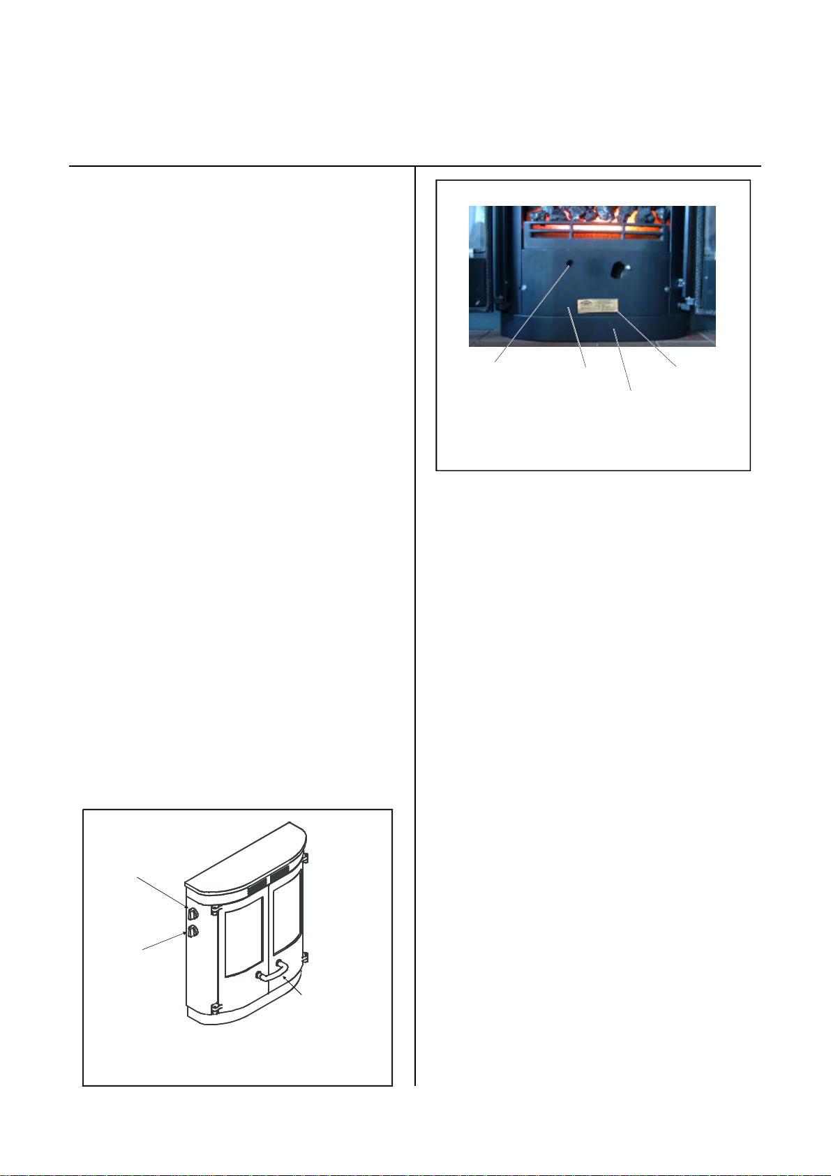
CONTROLLINGTHEBOILER
BurnerResetButton
LocatedThroughHole
InFrontPanel
Innerplate
SerialnumberLabel
Bottomplate
Theboileriscontrolledbythethermostatwhichison
thelefthandsideofthefire,itisthelowerofthetwo
controlknobs(seeFig.1.)Thissetsthetemperature
thattheboilerwilloperateat.ACentralHeatingTime
ClockorProgrammerwillnormallycontroltheheating
system.
ELECTRICFLAMEEFFECT&FANHEATER
Theelectricflameeffect operatescompletely
independentlyfromtheboilerandisswitchedonand
offbythetopcontrolknobonthelefthandsideofthe
fire(seeFig.1.)Turntheknobtoposition"1"to
operatetheflameeffect.Theflameeffectmaytakea
fewmomentstobecomeestablishedwhenfirst
switchedonafterlongperiodsofnotbeingused.
Position"2"isusedforthe1KWsettingoftheoptional
fanheateriffitted.Position“3”isthe2KWsetting.If
theroomtemperaturebecomesexcessive,theinternal
thermostatwillswitchtheheatertoblowcoolairuntil
thetemperaturefalls,whenitwillreverttoitsprevious
setting.
FlameEffect
andOptional
FanHeaterControl
Fig2.BurnerResetButton
IFTHEBURNERFAILSTOLIGHT
IftheburnerfailstolightthentheResetlightonthe
BurnerResetButtonmaylightup(seeFig.2.)This
situationisknownas“Lockout”inwhichcasewaitfor
1minuteandpressthere-setbutton(locatedthrough
theholeinthefrontpanelbehindthedoors.)The
burnerwillthentrytoigniteagain.
Iftheburnercontinuallygoestolockout,thenthecause
needstobeestablishedandtheproblemputright.The
mostcommoncausesarelackoffuel,orairinthefuel
line.Checkthattheoiltankisnotempty,andthatall
valvesareopen.Thetroubleshootingguidegives
furthersteps,someofwhichwillrequireactionbya
trainedOilEngineer.Donotpresstheresetbutton
morethanfivetimesinarowasthiscancausedamage
tothepump.
MAINTENANCE
Itisimportanttohavetheapplianceservicedeach
year.PleasearrangethiswithanOFTECapproved
Heatingengineer.Theflexibleoilsupplyhosemustbe
replacedevery2years
Boiler
Thermostat
Fig.1.Controls
TurnHandle
Clockwise
ToOpen
ReplacingTheFlameEffectBulb
Replacingthebulbintheflameeffectisasimple
operationthatcanbecarriedoutwithoutusingany
tools.
Ensurethattheflameeffectisswitchedoffbefore
attemptingtoreplacethebulb.Openthedoorsand
Page4
OLXV5.205.04
Page 5
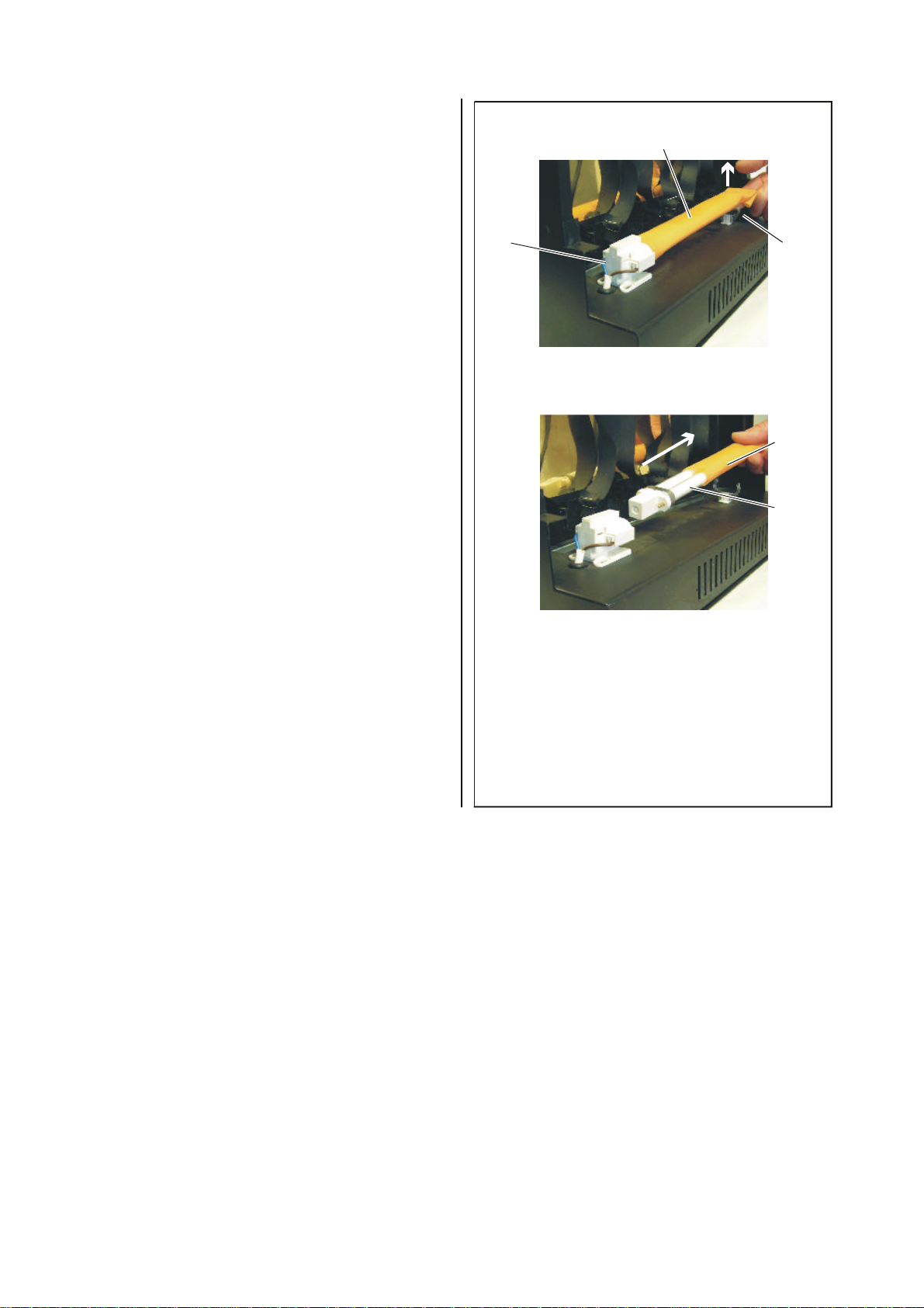
removethecoals.LiftofftheFrontFence.Liftoutthe
fibreglasscoaleffect.Lifttheright-handendofthe
bulbandcoveroutofitsclip,seeFig.3,thenunplug
thebulb,movingittowardstheright.Slidethecover
offanddiscardtheoldbulb.Slidetheoldcoveronto
thenew
bulbandinsertthebulbbaseintotheholder
ontheleft.Ensurethatthebulbispushedfully
home,thenlowertheright-handendandpressit
intotheclip.Replacethefibreglasscoaleffect,with
therearedgepassingjustunderthePerspex.Re-fit
thefrontfenceandreplacethecoals.
Sleeve
Holder
Clip
1)LiftBulbfromclip
Sleeve
Bulb
2)RemoveBulbfromHolder
Fig.3.FlameEffectBulbReplacement
Page5
OLXV5.205.04
Page 6

CharnwoodOLXOilFiredHearthBoiler
InstallationInstructions
HEALTHANDSAFETYPRECAUTIONS
Pleasetakecarewheninstallingtheappliancethatthe
requirementsoftheHealthandSafetyatWorkAct
1974aremet.
Sometypesoffirecementarecausticandshouldnot
beallowedtocomeintocontactwiththeskin.Incase
ofcontactwashwithplentyofwater.
Noasbestosisusedintheappliancebutifthereisa
possibilityofdisturbinganyasbestosinthecourseof
installationthenappropriateprotectiveequipmentmust
beused.
Whenhandlinginsulatingmaterialsasuitablefacemask
andprotectiveglovesshouldbeworn.
Takecarewhenhandlingfueloilwhichcancauseskin
irritation,avoidcontactwiththeskinorclothing,take
caretowashhandswellaftercontactwithfueloiland
beforeeating.Fueloilmustneverbetakeninternally.
STANDARDS®ULATIONS
Inadditiontotheseinstructionstherequirementsofthe
followingstandardsmustbefulfilled:
BS5410Pt1OilInstallationsUnder45kW
BS5449ForcedCirculationhotwatercentral
heatingsystemsfordomesticpremises
BS7671ElectricalWiringRegulations
boilerandaductedairsupplymustbeprovidedtothe
righthandsideoftheboileratthispoint.Atwometre
lengthofflexibleductingandfixingclipsaresupplied
withtheappliancetoconnecttheairinputfromthe
appliancesilencertotherigidplasticducting.Theair
pipeshouldbesealedintotheapplianceusingasilicone
sealant.Theductingshouldberunin50mmdia.(2")
plasticpipeandmustterminateinfreeair-preferably
eitheroutsideorinaventilatedloftspace.Theendof
theductingmustbefittedwithasuitablecageto
prevententrybybirdsorsmallmammals.Theducting
shouldbeboxedinwhereitpassesthroughlivingareas.
Thelengthofductingshouldbekepttoaminimum,
andthemaximumrecommendedlengthis10metres
incorporatingupto4bends.(Onebendisapprox.
equivalentto1metreofstraightpipe).
Providedthattheductingterminatesasdescribed
abovethereisnorequirementforaseparate
combustionairsupplyintheroominwhichthe
applianceisinstalled.However,iftheducting
terminateswithinalivingspacethentheremustbean
adequateairsupplyintothatroomtotallingatleast55
sq.cm.(8.5sq.inches)toprovidecombustionair.
CHIMNEY
LocalAuthorityBylawsandBuildingRegulations
regardingtheinstallationofOilBurningAppliances,
fluesandchimneysandTheControlofPollution(Oil)
Regulationsmustalsobeobserved.
Oilboilersshouldbeinstalledinaccordancewithgood
practiceasrecommendedbyOFTEC(TheOilFiring
TechnicalAssociationforthePetroleumIndustry,
Banstead,Surrey.Tel:01737373311.)
PERFORMANCE
Theoutputoftheboilerisadjustablebetween11-13
kW(38-44,000Btu/h),asmallamountofheatwillbe
givenouttotheroombutforpurposesofsizingthe
systemthisshouldbeignored.TheoptionalFanHeater
providesupto2KWofheattotheroom.
AIRSUPPLY
Theairsupplyforcombustionistakenfromwithin
thebuildersopeningontheright-handsideofthe
ThechimneyshouldcomplywithBS5410:Part1and
mustmeetBuildingRegulations.
Thediameterofthechimneymustnotbelessthan100
mm(4”)internaldiameter.
Astheboileroperatesathighefficiency,itisimportant
thatthechimneyiswellinsulatedinordertoprevent
condensationforming.
Brickorstonechimneysshouldbelinedwithasuitable
liner.Ifastainlesssteellinerisusedinabrickorstone
chimneythenitmustbeinsulatedbetweenthelinerand
thebrickworkinordertopreventcondensationthat
canreducethelifeofboththelinerandtheboiler.
Pumicelinerswillgivetherequiredlevelofinsulation.
Astheflueoutlettemperatureisbelow250°Cstainless
steelflexiblefluelinerssuitableforoilmaybefitted
directlyontotheappliance,althoughintheinterestsof
reducingfluenoiseitispreferabletousea600mm
lengthofrigidfluepipefromtheappliancetotheliner.
Page6
OLXV5.205.04
Page 7

Page7
OLXV5.205.04
Page 8

Iffluepipeisusedtoconnecttheappliancetothe
chimneyitmustbebetween100&125mm(4-5")
internaldiameter.
Thechimneyterminationmustnotbesubjectedto
downdraughts.Ifnecessaryananti-downdraughtcowl
maybefitted.Therequireddrawforthisapplianceis
0.17mbar(0.07inH2O).
HEARTHANDFIRESURROUND
per1moflengthdownwardsfromtheoiloutlettothe
sludgecockfittedattheoppositeend
.
PlastictanksshouldbeUVstabilisedforprotection
fromsunlight.Theydonotneedtostandonpiersbut
shouldbesupportedacrosstheentirebase.Referto
themanufacturersinstructionsforfulldetails.
Beawareofpollutionpreventionregulationsandthe
needforbundingifthetankisclosetowatercourses
ordrains.
Theboilerwaterwaystotallyenclosethecombustion
chamber.Thismeansthatthemaximumtemperature
belowtheboileris100°Candthereforea
constructionalhearthisnotrequired.
Thehearthandbasewithinthefireplaceopeningmust
bemadefromnon-combustiblematerialandmustbe
flatandlevel.Thehearthmustbeflattoalloweasy
fittingofpartsonthefire.Whenpositioningtheboiler
ensurethatthesideflangesontheboilercomelevel
withthefaceofthefiresurround.
Thefiresurroundshouldbemadefromnon
combustiblematerialandhaveopeningdimensions
showninFig.7.
OILSUPPLY
TheCharnwoodOilBoilerissetuptoburnKerosene
28secondviscosityoiltoBS2869Part21988Class
C2.Itcomescompletewithaflexibleoillineandshut
offvalve,towhichtheoilsupplylineshouldbe
connected.
Inordertoensurequietnessofoperationofthe
CharnwoodOLXasinglepipesystemisused.Theoil
storagetankshouldideallybepositionedwiththebase
ofthetankhigherthanthebaseofthefire.Whenthe
storagetankisbelowtheleveloftheburnerthenanoil
liftermustbeused.
Anoilshutoffvalveissuppliedwiththeboilertoallow
theburnertobeeasilydisconnectedandminimiseoil
spillage.
Anoilfiltershouldalsobefittedoutsidethebuilding,
adjacenttotheoiltank.
Aprotectivefirevalvemustbefittedintheoilsupply
line.Thephialsensorshouldbemountedintheburner
chamberThefirevalveshouldhaveacutout
temperatureof90°C.
Solderedjointsarenotpermittedintheoilsupplyline,
andallconnectionsmustbeproperlysealedtoprevent
oilleakageandairingress.
Someschematiclayoutsofoilsupplysystemsareshown
inFigs.4&5.
Whenconsideringwheretositetheoilstoragetank,
considerationshouldbegiventotheaccessrequiredby
fueldeliverylorries.Tankpositioningmustalsobein
accordancewithBS5410Part1andOFTECTechnical
Book3.
Oiltanksshouldhavethefollowingitems:
Avalvefittedtotheoutlet
Sludgevalve(onsteeltanks)
Oillevelindicator
Hingedfillandventcoverorseparatefill
connectionandvent.Thefillandventmustbe
eithersuitablycappedorhaveareturnbendto
keepoutdirtandwater.
Steeltanksshouldbemountedonsuitablesupports.If
theyaremountedonblocksorbricksthenadamp
proofmembraneshouldbefittedbetweenthe
supportsandthetank.Steeltanksshould slope20mm
OLXV5.205.04
Theoilsupplylineshouldentertheappliancefromthe
left-handsidebehindthesidepanel.Thefittingsupplied
withthefirefacilitatesthis.
Ifthesupplylineistoruninfrontofthefireplace
surroundthenitwillbenecessarytocutasectionfrom
theendofthebottomplateonthefiretogiveaccess
forthepipe.Itispreferabletobringthesupplyinfrom
behindthefiresurround.
Theoilsupplylinemaybeineither8or10mmdia.
copper,dependantonthelengthoftherun,however,
theconnectionontheapplianceisa10mm
compressionfitting.
ThesupplylineMUSTbeflushedoutinthefollowing
manner:-
Connectthesupplylinetothecompressionfitting
ontheservicevalveatthelefthandsideofthe
appliance,butdisconnecttheflexiblehosefromthe
othersideoftheservicevalve,andreplaceitwith
Page8
Page 9

thepushonpieceof12mmbleedtubesupplied.
Placetheotherendofthebleedtubeintoasuitable
receptacle,andflushoutthesupplylinebyturning
ontheservicevalve.Whentheoilisclean,turnoff
theservicevalve,removethebleedtube,andreattachtheflexibletubefromtheburner.Turnthe
servicevalvebackon,checkforleaks,andcleanup
anyspiltoil.
PREPARATIONOFFIREPLACE
Whenreplacinganexistingboiler,removeanyfireback
andinfillmaterialtoexposethebuildersopening.
Theopeningmustbeatleast400mmdeep(when
measuredfromthefrontfaceofthesurround,)600
mmwide(togiveaccesstotheboilerconnections,)and
650mmhigh(togiveaccesstotheflueconnection.
Ensurethatthebaseofthefireplaceislevelwiththe
hearthandthatthefaceofthesurroundisvertical.
Itisnecessarytohaveasmallcutoutinthefireplace
surroundatthebottomleftoftheopeninginorderto
bringtheoilandelectricalsupplytothefire.Itisalso
necessarytohaveasmallcutoutatthebottomrightof
theopeningtocleartheairinletduct.Seefig.7.
Vermiculiteinfill
aroundFlexible
Liner
Rockwoolinfill
aroundflexible
lineraboveclosure
ClosurePlate
Rockwool
insulation
around
Appliance
Fig.6.TypicalInstalation
usingflexibleflueliner
rightdowntoAppliance.
Theshadedareaonthefaceof
thesurroundistheminimumflat
arearequired.
670mm
100mmidsingleskin
flexiblefluepipe
Firesurroundwith
removablemetal
closurepanels
HighTemperature
Siliconesealant.
ApplianceConnector
Fluefixingbrackets
Jointcaulkedwith
glassfibreropeand
sealedwithhigh
temperaturesilicone
sealant.
CENTRALHEATINGSYSTEM
ThecentralheatingsystemmustcomplywithBS5449,
andshouldbeinstalledinaccordancewiththecurrent
goodpractiseguidelinesasadvisedbytheHVCA.
Centralheatingdesignisalargesubjectwhichitisnot
possibletodealwithadequatelyinthismanual.The
pointsthatareparticularlyrelevanttothisboilerare
dealtwithbelow.
Theheatingandhotwatersystemshouldnormallybe
fullypumped,althoughagravityhotwatersystemmay
beusedifitalreadyexists.
Therearenointernaldivisionsinthe boiler,andany
combinationofflowandreturntappingsmaybeused.
Ifitispossiblethendiagonalpairsoftappingsshouldbe
used,butpairsonthesamesidemaybeusedif
required.
Themaximumworkingpressureoftheboilermustnot
exceed3Bar(44psiorastaticheadof30m)
Inordertopreventabuildupofscaleandcorrosiona
suitableinhibitorshouldbeaddedtothesystem.
Whenreplacinganexistingboilerthesystemshould
770mm
50mm
Dim.A:
Max.470mm(181/2")
Min.405mm(16")
Dim.B:
Max.579mm(223/4")
Min.555mm(213/4")
50mm
65mm
110mm
Fig.7LimitingDimensionsOf
SurroundandOpening
bethoroughlycleanedbeforeconnectingthenew
boiler.
Fullyautomaticcentralheatingcontrolsmaybeusedto
givefullcontroloftheheatingandhotwater.When
designingthecontrolsystemitisimportanttonotethat
ifthesituationcanarisewheretheflowofwater
throughtheboilerisstopped,orsubstantiallyreduced,
whilsttheburnerisstillfiring,thenthiscanresultinthe
waterintheboilerreachingveryhightemperatures,or
evenboiling,beforetheboilerthermostatcansenseit
andswitchtheburneroff.Ifthisisapossibilitythen
Page9
OLXV5.205.04
Page 10

wirethecontrolstotheburnersothatitisswitchedoff
atthesametimeasthepumpormotorisedvalves.
Thisusuallymeanswiringthesupplytotheburnerinto
theoutputfromthecentralheatingprogrammer.
FITTINGTHEFIRE
ResetButton
OilPressure
GaugePort
Burner
Control
Unit
IgnitionUnit
(BehindControlUnit)
Photocell
AirControl1-10
AirControl1-10
AirInlet
Manifold
Unpackthestoveandremoveitfromitswooden
pallet..Ifafluelineristobeusedthenthisshouldbe
fittedinthechimneybeforefittingthefire.Theliner
willnormallycomedowntoafixingplateandashort
lengthof316Stainlesssteelfluepipeisthenusedto
connecttheboilertotheliner.Alternativelytheliner
maybefitteddirectlytotheboiler,inthiscaseensure
thattheliner isadequatelysupportedandthatitwill
notvibratewhentheapplianceisinuse.UsetheFlue
Fixingbracketsandselftappingscrewssuppliedtofix
thefluesecurelytotheboiler(seeFig.12.)Mineral
fibreorfibreglassshouldbeusedtoreducevibrations
andinsulatetheboilerandflue.Thespacebetweenthe
flexiblelinerandthechimneyshouldbefilledwith
loosevermiculiteinfillretainedbyasuitableplateinthe
chimneyabovetheboilertoallowfutureaccesstothe
boilerwithoutremovingtheinfill(seeFig.6).A
suitableraincapshouldbefittedtothetopofthe
chimney.
Positionthefiresothattherearfaceofthesideflanges
comesflushorveryslightlyinfrontofthefaceofthe
firesurround.
Maketheflueconnectiontotheappliance,ensuring
thatthefluepipeiswellsealedtotheboiler,andfixed
securelyusingthefixingscrewsandbrackets,seeFig.
10.
Connecttheheatingsystemtotheboilerensuringthat
thesystemventscorrectly.Fillthesystemwithwater
andcheckforleaks.
OilPump
NozzleCoverPlate
FuelSolenoidvalve
AirPressureSwitch
Fig.8.OilBurnerAssembly
ShownRemovedfromBoiler.
bafflesfitted,anditisrecommendedthatthesebe
checkedforpositionbeforeinitialfiring.Ifitbecomes
necessarytore-fitthebafflesandbricks,followthis
procedure:-
Isolatefromthemainssupply,openthedoorsandlift
upandremovethebottomplate.SeeFig2.Liftoffthe
fenceandthecoaleffect.Loosenthefixingscrewat
eachsideoftheinnerplate,slideoutwardsintothe
slot,andliftofftheinnerbottomplate.LiftthePerspex
paneloutofthefireandundothetwowingnutsonthe
backpanel.Unplugthemainscablefromthebottomof
theflameeffect.Theflameeffectmaythenbelifted
clear.Theboileraccessdoorisnowvisible,andis
removedbyundoingthe4brassnutswitha10mm
socket.
Taketheitems1-5inorderandlowertheminto
positioninthebottomofthecombustionchamber.
Assemblethemtogetherinthispositionsothatboth
sideboardsaretightinagainstthetop&backboards,
andthefrontfaceofthetopboardishardupagainst
ELECTRICALCONNECTION
Theboilercomespre-wiredwithtwolengthsof3-core
cable.Theblackcableisfortheoilburner,thewhiteis
fortheflameeffectandoptionalfanheater.Connect
theblackcabletotheoutputfromthecentralheating
programmer,ensuringthatthesupplyisviaa3amp
fusedswitchedspur.Connectthewhitecabletoa
separate3ampfusedswitchedspur.Ifafanheateris
fitted,thisfusemustbe10amp.Ensurethattheearth
connectionsaremade.
COMBUSTIONCHAMBERASSEMBLY
Theboilercomeswiththeinternalinsulationbricksand
OLXV5.205.04
Page10
BleedScrew
BleedHose
ConnectionPoint
Fig.9.OilPumpDetails
OilPressureAdjustmentscrew.
ClockwisetoIncrease,
Anti-ClockwisetoDecrease.
Page 11

TopBaffle
Nibsatfront
45°Chamfer
AssemblyOrder:
1.Base(FibreWool)
2.Back
3.RHSide
4.LHSide
5.Top
5
45°Chamfer
45°Chamfer
Note!Numbersetchedontobafflesmustbe
incorrectorientationwhenassembled.
Fig10.BaffleArrangement
theinnerfrontoftheboiler.Thereshouldbeagapat
thebackofapprox.25mm,andequalgapsatthe
sides.Thebottombaffle(No.1)isnowcarefully
loweredintoposition,sothattheguidesonits
undersideholdtheinsulationpanelsinplace.When
assembledtheNo1shouldbeclearlyvisible,theright
wayup.Theremainingbaffles(Nos.2-4)are
assembledinorder,withthenumbersfacingthefront
ofthestoveasshowninFig10.Theaccessdoorisnow
re-fitted.Ensurethattherubbersealispushedfully
hometotheframe,andthatthe4brassnutsare
tightenedevenly.
3
2
4
CombustionChamberInsulationBoard
1
OrderofAssembly
FINISHINGTHEINSTALLATION
Onceallwater,oilandelectricalconnectionshavebeen
madeandtestedtheinstallationcanbefinished.Fit
glassfibreinsulationmaterialaroundtheboilerandflue
inthebuildersopening.Thiswillbothhelppreventheat
lossandreducenoisetransmission.Fitthefire
surround.
WARNING
Oncetheinstallationiscompleteensurethattheair
controlissetatmaximum(No.10)beforethe
burnerisfired(seeFig.8.)Otherwisesootingmay
occur.Thiswillbere-adjustedduringcommissioning.
Page11
OLXV5.205.04
Locatethisfacehard
againstinnerfront
boilerface,giving25mm
gapatrear,&40mmat
frontsides.
Fig11.CombustionChamberComponents
Page 12

COMMISSIONING
Theburnersarepre-setatthefactory,butmustbe
fine-tunedoncompletionoftheinstallation.Thisisa
conditionoftheguarantee.
Beforefiringtheboilercheckthatthebafflesandblast
chambercomponentsarefittedinthecorrectpositions
asdescribedaboveandshowninFigs.10&11.
Ensurethattheheatingsystemisconnectedandfilled
withwaterbeforeattemptingtofiretheboiler.
Tosettheoilpressureandtheairsettingitisnecessary
toremovetheinnerbottomplate.Isolatefromthe
mainssupply,openthedoorsandliftupandremove
thebottomplate.SeeFig2.Liftoffthecoals,thefence
andthecoaleffect.Loosenthefixingscrewateachside
oftheinnerplate,slideoutwardsintotheslot,andlift
offtheinnerbottomplate.Accesstotheboiler
samplingpointisbehindtheflameeffect.Togainaccess
liftthePerspexpaneloutoftheflameeffectandundo
thetwowingnutsonthebackpanel.Unplugthemains
cablefromthebottomoftheflameeffect,whichmay
thenbeliftedclear.Theboilersamplingpointisatthe
topoftheaccessdoor,usea5mmallenkeytoremove
theblankingscrew.Settheaircontrolfullyopen(No.
10)beforetheinitialfiring.Theelectricalpowermaybe
turnedbackontotesttheburner.
thermostattoMed.Afterafewsecondsyoushould
heartheburnerignite.Ifnecessarybleedthepump.
RefertoFig.9.Fitthepieceof4mmplastichose
providedontothebleedport,placetheendofthehose
intoasuitablereceptacleandopenthebleedscrew
takingcarenottospillanyoil.Whenbleedingthe
pumpwillbequitenoisy.Oncealloftheairisoutof
thesystemclosethebleedscrewandremovethehose.
Takecaretomopupanydropsofoilspilt.
FlueFixingBrackets
AirInlet
Connection
TheburnercomponentsareshowninFig.8.
Turnonthesupplytotheprogrammer,setthe
programmertogiveheatingandhotwaterandturnthe
Boilertappingsare1”BSPFemale,
2eachside
547
520
250
261
365 170 548
CharnwoodOLXOverallDimensions
(alldimensionsareinmm)
Fig.12.AirInletand
FlueFixings
654
(693with
optional
fanheater)
394 62
ø130
255
Page12
OLXV5.205.04
Page 13

Writethedateontheflexibleoillinelabel.The
flexibleoillineMUSTbereplacedevery2years.
Allowthefiretorunfor20-30minutesbeforechecking
thesootandCO2readings.Thesamplingpointison
theboileraccessdoor.Theaircontrolissituatedonthe
frontoftheblackrubberairmanifoldwhichistowards
therightoftheburner,asshowninFig.8.Initiallysetto
No.10,theburnerwillbeburningwithexcessairand
withtheoilpressuresetatamid-rangesetting.Fita
pressuregaugetothepressuregaugeportshownin
Fig.8andadjusttotherequiredsetting(100-140psi.)
Afteradjustingthepumppressureallowthefiretorun
forapproximately10minutesbeforecheckingthe
smokereading.Reducetheairinletbyslackeningthe
nutinthecentreofthemanifold,movingthepointer
clockwisetoalowernotchandre-tighteningthenut.
Whensootoccurs,graduallyincreaseittogive
combustionfreeofsoot.(10=maxair,1=minair).
Thisshouldgive11–12%CO2and0-1Smokewitha
fluetemperatureofapproximately180°Cabove
ambient.Measurementstakenattheboileraccessdoor
willgiveaslightlyhighertemperature(approx.220°C
aboveambient)thanreadingstakenactuallyintheflue.
Amodernburnerworkswith lessexcessairandoften
alsowithsmallernozzlesthanoldermodels.This
increasestheefficiencybutalsotheriskof
condensationinthechimney.Theriskincreasesifthe
areaofthechimneyflueistoolarge.Thetemperature
ofthefluegasesshouldexceed60°Cmeasured0.5
metresfromthechimneytop.Ifnecessarysomeofthe
followingmeasuresmaybetakentoraisethechimney
temperature:
Insulatethechimneyincoldattics.
Installachimneyliner.
Installadraughtregulator(dilutesthefluegasesduring
operationanddriesthemupduringstandstill).
Increasetheoilquantity.
Raisethefluegastemperaturebyremovingsomeof
thebaffleplatesintheboiler.
Re-fittheElectricFlameeffectandcheckitsoperation.
Theflamepatternmaytakeafewminutestobecome
established,particularlywhenthefireisswitchedonfor
thefirsttime.Arrangethecoalssuppliedwiththe
applianceontopofthefibreglasscoaleffecttoproduce
abeautifulfire.
Advisethecustomerontheuseoftheboiler,andthe
systemcontrols.Alsoadviseoftheneedforannual
servicingoftheboilerbyanOFTECtrained&
registeredtechnician.LeavetheseOperatingand
InstallationInstructionswiththecustomer.
Page13
OLXV5.205.04
Page 14

OLXBoiler-Specifications
Max.AllowableOperatingTemperature95°C
Max.AllowableOperatingPressure3bar(PressureClass2)
TestPressure4.5bar
HeatOutputRange11-13kW
HeatInputatRatedOutput15kW
OilPumpPressure110-140psi
RequiredFlueDraught0.07inHO(0.17mbar)
ExitFlueGasTemp205°C
ExitFlueGasMassFlow……kg/s
ExitFlueConnectionDiameter130mmsockettotake125mm(5in)or
100mm(4in)pipe
AirInletDiameter55mmsockettotake50mm(2in)pipe
Max.RecommendedAirPipeLength10M+4x90°SweptBends
Water-sideResistance
4.1mbar@DT=10°C
@flowrate2.9litres/min1.5mbar@DT=20°C
RangeofTemperatureControl40-90°C
SafetyThermostatTemperature 110°C
FuelTypeUsedKerosene28second
BoilerTypeOn/OffType
BoilerTappingsize1inBSPFemale
ElectricalProtectionIP20
EarthingTerminalCopperFlashedSteel
ElectricalSupply240v50Hz
ElectricalPowerInput@240vac(standard)200Watts
(withfanheater)2200watts
FuseinFlameEffect250v2Ax20mm
FusesRequiredinPowerSupply
FlameEffectonly3A240V
FlameEffect+FanHeater10A240V
Burner3A240V
FireValveOperatingTemperature90°C
BoilerWaterVolume23.4Litres
TotalWeightofStove140Kg
2
Page14
OLXV5.205.04
Page 15

MainsInput
from13Amp
FusedSpur.
MainsInput
fromTimer
SwitchedLive.
Fusedat3Amp.
CharnwoodOLX
WiringDiagram
AboveSerialNo.1562
IECLeadSocketto
FlameEffect
E
L
N
P1
1
RotarySwitchSW1
TypeRPSBC20M90
2
3
SocketTo
Optional
FanHeater
E
N
L
31
21
11
DualActing
Thermostat
32
22
12
TR
TB
TS1
OutletSocket Plugto
L1
(1+)
L2
(1-)
N
(2-)
E
(2+)
Skt3
IECChassis
Skt1
E
L
N
FanHeater
Plug
Brown
1+
Black
1-
Blue
2-
Green/
Yellow
2+
E
N
L
Skt2
IECFused
ChassisPlugin
FlameEffect
WireColours
fromFanHeater
Skt4
E
N
L
IECLead
Burner
E
1ampantisurgefuse
L
N
FluorescentLight
Ballast
Fan
FlameEffect
SatronicControlTerminals
1 2 3 4 5 6 7 8 9
A B CN N N S2
Photocell
IgnitionUnit
Oil
Pump
Fan
Diode
BurnerControl
10
AirPressure
Switch
P
SolenoidValve
(Oil)
ThermostatMountingBox
Page15
OLXV5.205.04
Page 16

CharnwoodOLX
ElectrodeSettings
3.0±0.20.5±0.5
Alldimensionsareinmm
9.0±1.0
Page16
OLXV5.205.04
Page 17

IssueC
CharnwoodOLXMk.2
PartsList
53
48
54
36
391819
29
12
11
51
35
50
32
31
21a
30
40
37
46
16
45 44
47a 47b 47c
43
7
41
42
33
25a
24b
24a
23a
21a
21a
21a
38
49
17
34
142615
NOTE!
Mk.3ReplacementBurnersfor
appliancesbeforeSerialNo.
45****1562requirebracket
toaligncontrolboxwithre-set
hole.
55
6
52
102713204
8289
ItemPartNo.DescriptionItemPartNo.Description
3*008/KV35SDoorSealSetInc.Adhesive38004/TV03AccessDoor
4006/KV18GlassInc.GlassChannel39004/TV25ThermostatMountingBox
5*008/TV95GlassSeal(Neoprene)40004/TV33ThermostatPhialClampingPlate
6004/KV23GlassRetainer41008/TV17InnerFrontInsulation
7002/TV07FrontFirebar42010/TV14InnerFrontPlate
8008/KV16R.H.DoorHandle43010/TV43InnerFrontPlateFixingBracket
9002/KV14DoorCatchCam44008/TV86AirInletGasket
10008/KV13L.H.DoorKnob45008/TV49AirInletManifold
11008/TV19ThermostatKnob46010/TV84/1AirInletSideCover
12008/TV20FlameEffectKnob47a010/TV108AirControl-LocationDisk
13008/BW39/SHingePinSet(4perset)47b010/TV109AirControl-Pointer
14008/TV80FluorescentLamp47c010/TV110AirControl-Adjuster
15008/TV78AmberLampSleeve48010/TV42SFlueFixingBracket(setof3)
16040/TV69ResetButtonExtension49011/PV27BackCeramicGasket
17008/TV09AccessDoorInsulation50040/TV77ServiceValve&Elbow
18008/TV22Thermostat51040/TV94BurnerMountingFlange
19008/TV24FlameEffectRotarySwitch52M12HalfNuts
20008/TV27HingePost53005/TV06/##LowerTopPanel-forFanHeater
21a01 1/TV106BlastChamberInsulationBoardSet54008/TV111FanHeater
23a010/TV31Baffle-No.1
24a010/TV47ABaffle-No.2.
24b010/TV47BBaffleNo.3
25a010/TV48ABaffle-No.4
26008/TV13FibreglassCoalEffect
27003/TV01/##L.H.Door
28003/TV02/##R.H.Door
29005/TV04/##L.H.SidePanel
30005/TV05/##R.H.SidePanel
31005/KV06/##LowerHoodPanel
32005/KV09/##TopHoodPanel
33005/TV16/##BottomPanel
34008/TV11FlameEffectCartridge
35008/TV15OilBurner
36001/TV10BFirebox/Boiler(OLX)
37004/KV50PanelFixingBracket
*Theseitemsarenotshownonthedrawing
##Pleasespecifycolourwhenordering
55010/TV137ControlBoxOffsetBracket
Toobtainsparepartspleasecontactyourlocalstockist
givingModel,PartnumberandDescription.Incaseof
difficultycontactthemanufacturerattheaddressshown.
ThisdrawingisforIdentificationpurposesonly.
CHARNWOOD BishopsWay,Newport,IsleofWightPO305WS,UnitedKingdom
T:+44(0)1983537799F:+44(0)1983537788charnwood@ajwells.co.ukwww.charnwood.com
Page17
OLXV5.205.04
Page 18

IssueA
CharnwoodOLXBurnerMk.3
PartsList
TheseItemsshownRotated
40
41
14
11
23
17
42
3
15
12
24
5 34 6
7
35 8
16
30
27
4
26
2
28
1
18
31
19
22
9
29
25
38
37
33
13
10
40
20
21
Item Part No. Description Item Part No. Desc ription
1 040/TV61 Nozzle - 0.4 80° EH 38 040/TV124 Solenoid V alve
2 040/TV154 ElectrodeMounting Block 39 040/TV123 Solenoid Plug & Lead
3 040/TV153 Electrode 40 040/TV161 Burner MountingFlange
4 040/TV140 Nozzle Holder 41 040/TV162 Mounting FlangeGasket
5 040/TV155 Nozzle Holder Cover Plate 42 Electrode fixingscrew
6 040/TV141 Al.Washer
7 040/TV143 Banjo Union
8 040/TV142 Fibre Washer
9 040/TV144 Banjo Bolt
10 040/TV160 FlexibleOil Line
11 040/TV63 Blast Tube Seal
12 040/TV112 Photocell Plug-in Type
13 040/TV113 Solenoid Coil Plug-in Type
14 040/TV164 Blast Tube
15 040/TV151 AirGuide in Blast Tube
16 040/TV28 Burner Chassis Plate
17 040/TV74 Fan Motor & Impeller
18 040/TV92 Pump Mounting Bracket
19 040/TV72 Oil Pump
20 040/TV71 Ignition Unit
21 040/TV75 Control Box
22 040/TV54/A Fan Mounting Ring
23 040/TV158 Photocell Plug & Cable
24 040/TV159 Photocell Holder
25 040/TV68 Air Pressure Switch
26 040/TV148 Gauge Port Elbow
27 040/TV149 Gauge Port Plug
28 040/TV150 OilT Connector
29 040/TV69 Reset Button Extension
30 040/TV152 Blast Tube Mounting Flange
31 040/TV146 OilPipe (Pump to Sol.Valve)
33 040/TV145 OilPipe (Sol.Valve to Nozzle)
34 040/TV15~1 Burner Casting
35 040/TV163 Fan Washer
37 040/TV147 OilElbow 8/10mm male/male
Toobtainsparepartspleasecontactyourlocal
stockistgivingModel,PartnumberandDescription.
Incaseofdifficultycontactthemanufactureratthe
addressshown.
Thisdrawingisforidentificationpurposesonly.
CHARNWOOD BishopsWay,Newport,IsleofWightPO305WS,UnitedKingdom
T:+44(0)1983537799F:+44(0)1983537788charnwood@ajwells.co.ukwww.charnwood.com
Page18
OLXV5.205.04
Page 19

 Loading...