

Page 1
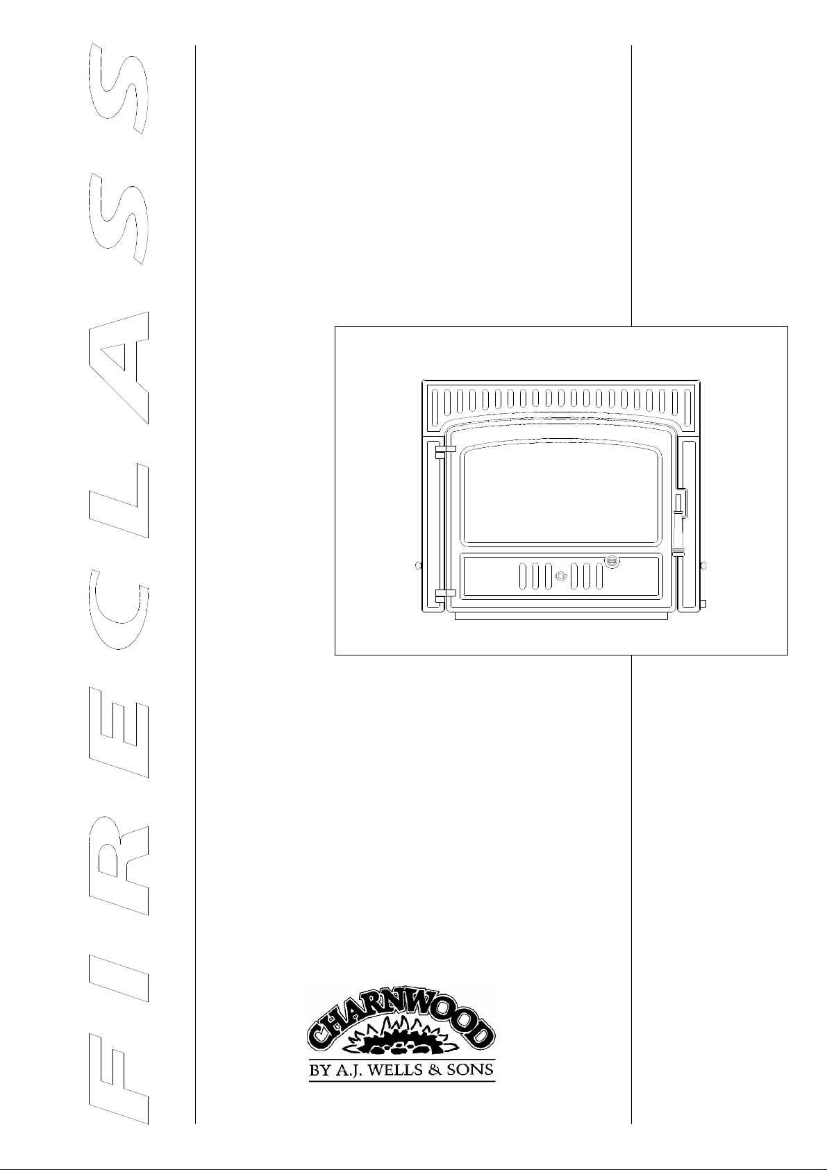
CHARNWOOD FIRECLASS
OPERATING
AND
INSTALLATION
INSTRUCTIONS
Bishops Way, Newport, Isle Of Wight, PO3O 5WS
Tel.(01983)527552 Fax.(01983)821267
Page 1
Fireclass/0892
Page 2

OPERATING INSTRUCTIONS FOR THE
CHARNWOOD FIRECLASS
GENERAL POINTS
Before lighting the stove check with the installer that the
work and checks described in the installation instructions
have been carried out correctly and that the chimney has
been swept, is sound and free from any obstructions.
WARNING Do not fit an extractor fan in the same room
as this appliance as this can cause emission of smoke and
fumes into the room.
If the stove is fitted in place of an open fire then the
chimney should be swept one month after installation to
clear any soot falls which may have occurred due to the
difference in combustion between the stove and the open
fire.
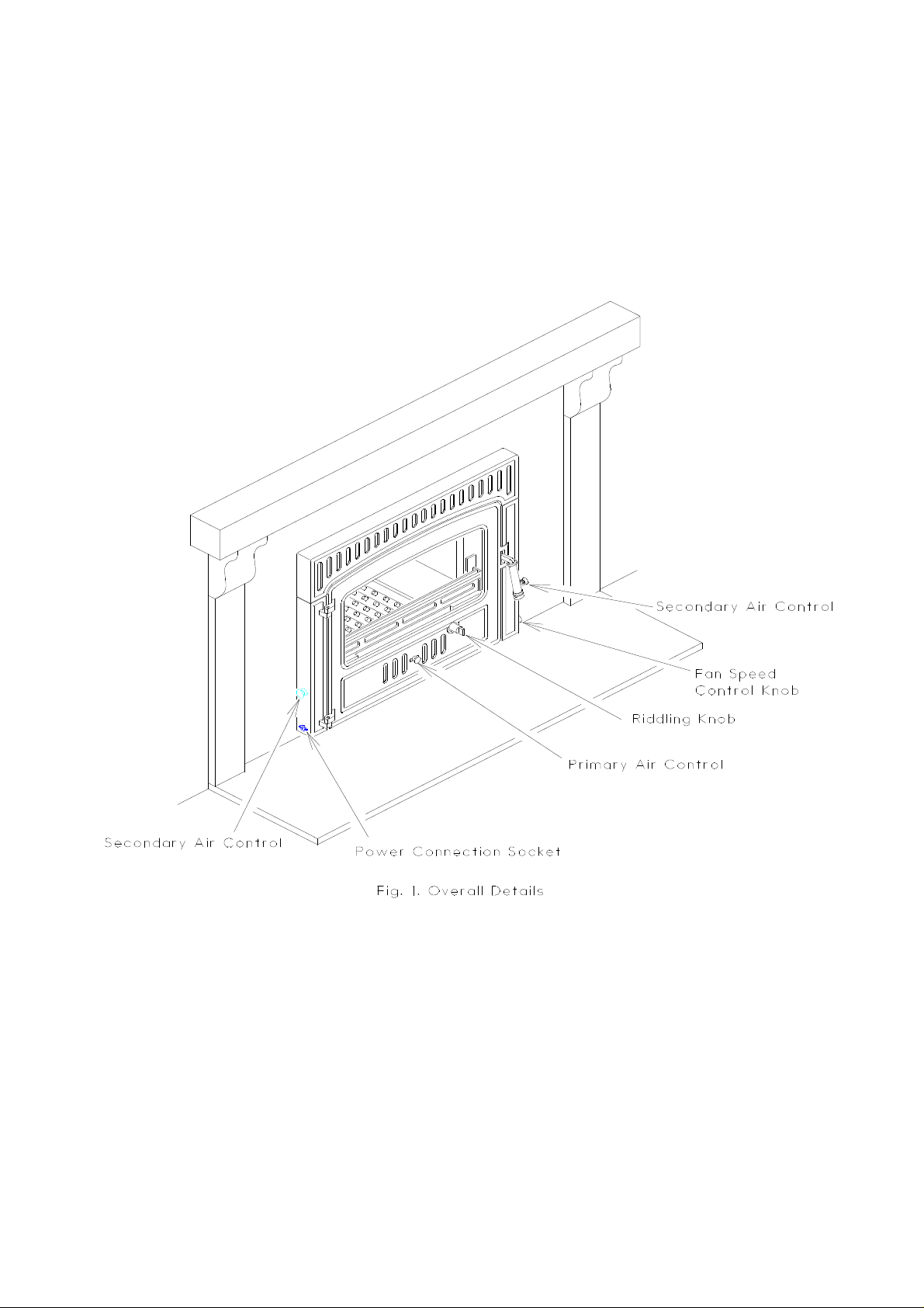
Fig. 1. shows the main parts of the fire and the
descriptions used throughout these instructions. If spare
parts are needed then please refer to the exploded
drawing at the end of these instructions to find the
relevant part numbers.
When using the stove in situations where children or
infirm people are present please use a fire guard to
prevent accidents. The fire guard should be manufactured
in accordance with BS 6539.
2’’ or 50 mm in size). The coal should be dry.
When burning coal a little extra care is needed. Please
take note of the section ‘‘Special Points For Burning
Coal’’.
Wood
Only dry well seasoned wood should be burnt on this
appliance as burning wet unseasoned wood will give rise
to heavy tar deposits. For the same reason hard wood is
better than soft wood. Burning wet unseasoned wood will
also result in considerably reduced outputs. The wood
should be cut and split and then left to season in a well
ventilated dry place for at least one year but preferably
two years before use.
Peat
Ensure that the peat is well dried before use. Burning wet
peat will give rise to heavy tar deposits and reduced
outputs.
PETROLEUM COKE IS NOT SUITABLE
FOR USE ON THIS APPLIANCE, ITS USE
FUELS
The following fuels may be burnt on this stove. Please
pay careful attention to the special points regarding each
type of fuel as they will help you to get the best from
your stove. It must be remembered that only smokeless
fuels may be burnt in smoke control areas on this stove.
If you are not sure whether you are in a smoke control
area, then please check with your Local Authority.
Smokeless Fuels
The following smokeless fuels may be burnt on this
appliance:
Anthracite Stove Nuts,
Coalite,
Homefire,
Maxibrite,
Welsh Dry Steam Coal (Large Nuts).
Coal
Housecoal doubles, trebles or cobbles may all be burnt.
Do not use singles, small nuts, or coal dust
It is important that large size coal is used (ie. larger than
WILL INVALIDATE THE GUARANTEE
At first you may find it helpful to try several fuels to find
the most suitable. If you are unable to obtain the fuel you
want ask your supplier, an approved fuel distributor, or
your local British Coal office to suggest an alternative.
MULTIFUEL GRATE
Your Charnwood stove is fitted with a multifuel grate
which enables solid fuel, wood and peat to be burned
equally effectively.
The grate has two positions. One for solid fuel, the other
for wood and peat. When in the solid fuel position ash
can fall through the grate and into the ashpan. When in
the wood position ash is able to build up on the grate as
is necessary for effective wood or peat burning.
Movement of the grate from one position to the other is
effected using the tool supplied. The grate is put into the
wood position by moving the tool direction of the arrow
‘W’ (marked on the handle of the tool) until the tool is
vertical. The grate is put into the solid fuel position by
moving the tool in the direction of the arrow ‘C’ until the
tool is horizontal.
If a mixture of wood and solid fuel, or peat and solid
Page 2
Fireclass/0892
Page 3
Page 3
Fireclass/0892
Page 4

fuel, is to be burnt then keep the grate in the solid fuel
position.
Care should be taken to ensure that ash is cool before
emptying it into plastic liners or bins.
LIGHTING
Set the grate into either the wood position or the solid
fuel position as required. Place some paper and dry
kindling wood or fire lighters on the grate and cover with
a small amount of fuel. Open the air slide in the door
fully and light the paper or fire lighters. Close the door
and allow the fire to burn until the fuel is well ignited
then load with more fuel close the air slide in the door
and adjust the secondary air control to the required level.
On initial lighting, the stove may smoke and give off an
odour as the silicon paint with which the firebox is
painted reacts to the heat. This is normal and will cease
after a short time. In the meantime the room should be
kept well ventilated.
Before relighting the stove, riddle, remove any clinker
from the firebed and then empty the ashpan.
CONTROLLING THE FIRE
The fire has three air controls as shown in Fig. 1. The
slide in the door is for use when lighting the stove and
for boosting the fire. It is also used when burning
smokeless fuels or coal. To close it completely tighten
the knob. The secondary air controls are used for
controlling the fire in normal use - they also help to keep
the glass clear.
Always close the door tightly after replacing the ashpan.
To make ash removal easier there is a special Charnwood
ash carrier available. This may be purchased from your
supplier, or in case of difficulty, directly from ourselves.
RIDDLING
When burning wood or peat, ash should be allowed to
build up and generally riddling every other day will be
sufficient.
When burning solid fuels riddling twice a day is usually
sufficient.
The fire should be riddled with the door shut. Place the
tool on the knob and rotate between the horizontal and
the 45 degree position several times as shown in Fig. 2.
Too much riddling can result in emptying unburnt fuel
into the ashpan and should therefore be avoided. Clinker
should regularly be removed from the firebed.
After riddling, the grate should be put back into the wood
or solid fuel position as required (the tool should be
vertical for wood or horizontal for solid fuel).
From time to time, particularly when burning coal or
smokeless fuels, the fire may benefit from being poked. It
will also be necessary to occasionally clear the ash from
the side plates onto the middle of the grate.
Due to variations between different installations a certain
amount of experimentation will be necessary to find the
most suitable setting for the controls. Generally you
should find that keeping the air slide on the door closed
and using the secondary air to control the fire will give
the most satisfactory results and keep the glass clear.
FAN OPERATION
There is a thermal cut out linked into the fan control.
This means that the fan will not operate until the stove
warms up. The fan is turned on and off at the mains
supply. To control the speed of the fan turn the knob on
the right hand side of the stove to give the desired
circulation. Turn the knob clockwise to increase or
anti-clockwise to decrease the circulation.
ASH CLEARANCE
The ashpan should be emptied regularly before it
becomes too full. The most convenient time to remove
the ash is just before riddling the stove since the ash will
then be at its coolest.
Never allow the ash to accumulate in the ashpan so that it
comes in contact with the underside of the grate as this
will seriously damage the grate bars.
REFUELLING
Keep the firebox well filled but do not overfill to prevent
fuel from spilling over the top of the front fire bars. Take
care, especially when burning wood, that fuel does not
project over the front fire bars or damage to the glass
may be caused when the doors are closed.
OVERNIGHT BURNING
Empty the ashpan, if necessary, and then riddle the fire if
you are burning solid fuel. If the fire is very low then it
may be necessary to add a little fuel and open the air
control for a brief period until the fire is burning brightly
before loading with fuel. When burning wood use large
logs overnight as they will burn more slowly than small
ones. Some experimentation may be necessary to find the
setting most suitable for the particular fuel used and the
draw on the chimney. The knob on the air slide in the
door may be tightened to close the slide completely. If
the secondary air controls are completely closed then
some blacking of the glass is likely to occur. They may
therefore be left slightly open in most cases.
To revive the fire, empty the ashpan if necessary, riddle,
(when burning solid fuel), and open the air controls.
When the fire is burning well load on more fuel as
Page 4
Fireclass/0892
Page 5

Page 5
Fireclass/0892
Page 6

necessary and adjust the air controls as required.
SPECIAL POINTS WHEN
BURNING COAL
When burning housecoal never completely close the
secondary air controls.
forward and then lower it. Use the tool to push any sooty
deposits up the plate until they fall off the back and into
the fire. Return the throat plate to it’s correct position (as
shown in Fig. 3.) - raise the front of the plate, push it
back and then lower it onto the retaining lugs.
CHIMNEY SWEEPING
When loading the stove take care not to smother the fire,
instead fill the firebox in two stages waiting between
each stage for the flames to appear above the fire.
After a period of slumbering always open the air control
for a few minutes before opening the doors.
Burning coal will produce more soot deposits than other
fuels, especially if the fire is run at low levels for long
periods. It is therefore vital to clean the throat plate
regularly, weekly cleaning is recommended and in some
cases it may be necessary to clean it daily.
CLEANING AND MAINTENANCE
The stove is finished in vitreous enamel. To clean the
surfaces simply wipe over with a dry cloth. Abrasive
pads and scouring cleaners must not be used as these will
damage the finish. Care should be taken not to knock the
enamel with hard objects as it will chip.
The glass in the doors is a zero expansion ceramic glass
which will not crack due to the heat of the fire. Before
cleaning the glass open the door and allow it to cool. Use
a damp cloth to remove any deposits, do not use any
abrasive or scouring cleaners as this will damage the
glass. If necessary a proprietory stove glass cleaner or
ceramic hob cleaner may be used.
If the stove is not going to be used for a long period (for
instance in the summer) then to prevent condensation and
hence corrosion, fully open the air controls and leave the
door ajar.
After long periods where the stove has been out of use
the chimney and stove flueways should be cleaned before
lighting.
For the stove to operate correctly it is important that the
door seals are in good condition. Check that they do not
become worn or frayed and replace them when necessary.
THROAT PLATE AND FLUEWAY
The chimney should be swept at least twice a year. In
most installations it will be possible to sweep the
chimney through the appliance.
First remove the front firebars and the throat plate. Then
sweep the chimney ensuring that soot is removed from all
horizontal surfaces after sweeping.
In situations where it is not possible to sweep through the
appliance the chimney must be swept through the soot
door which your installer will have fitted. After sweeping
the chimney the appliance flue outlet and the flue pipe
connecting the stove to the chimney must be cleaned with
a flue brush.
After clearing any soot from the stove replace the throat
plate and the front firebars.
Different types of sweep’s brushes are available to suit
different flueways. For standard brick chimneys a wire
centre sweep’s brush fitted with a guide wheel should be
used. For pre-fabricated insulated chimneys the manufacturers instructions with regard to sweeping should be
consulted.
TROUBLE SHOOTING
Fire Will Not Burn.
Check that:
l the air inlet is not obstructed in any way,
l that chimneys and flueways are clear,
l that a suitable fuel is being used.
Fume Emission.
WARNING NOTE: PROPERLY INSTALLED AND
OPERATED THIS APPLIANCE WILL NOT EMIT
FUMES. OCCASIONAL FUME FROM DE-ASHING
AND RE-FUELLING MAY OCCUR. PERSISTENT
FUME EMISSION IS POTENTIALLY DANGEROUS AND MUST NOT BE TOLERATED. IF FUME
EMISSION DOES PERSIST, THEN THE FOLLOWING IMMEDIATE ACTIONS SHOULD BE TAKEN:
CLEANING
It is important that the throat plate and all the stove
flueways are kept clean. When burning smokeless fuels
they should be cleaned monthly. When burning other
fuels they should be cleaned weekly.
The throat plate and flueways may be cleaned with a low
fire still burning. Lower the throat plate using the tool.
To do this engage the tool in the throat plate pull it
Fireclass/0892
A) OPEN DOORS AND WINDOWS TO VENTILATE THE ROOM.
B) LET THE FIRE OUT AND SAFELY DISPOSE
OF FUEL FROM THE APPLIANCE.
C) CHECK FOR FLUE OR CHIMNEY BLOCKAGE, AND CLEAN IF REQUIRED.
D) DO NOT ATTEMPT TO RELIGHT FIRE UNTIL
CAUSE OF FUME HAS BEEN IDENTIFIED, IF
NECESSARY SEEK PROFESSIONAL ADVICE.
Page 6
Page 7

The most common cause of fume emission is flueway or
chimney blockage. For your own safety these must be
kept clean.
Fire Blazing Out Of Control.
Check that:
l the air controls are closed,
l the door is properly closed,
l a suitable fuel is being used,
l the door seals are in good condition.
Chimney Fires.
If the chimney is regularly swept properly chimney fires
should not occur. However, if a chimney fire does occur
close both of the air controls, and tightly close the door
of the appliance. This should cause the chimney fire to
go out in which case the controls should be kept at the
minimum setting until the stove has gone out. The
chimney and flueways should then be cleaned. If the
chimney fire does not go out when the above action is
taken then the fire brigade should be called immediately.
After a chimney fire the chimney should be carefully
examined for any damage. Expert advice should be
sought if necessary.
Page 7
Fireclass/0892
Page 8

INSTALLATION INSTRUCTIONS FOR THE
CHARNWOOD FIRECLASS
HEALTH AND SAFETY PRECAUTIONS
Please take care when installing the stove that the
requirements of the Health and Safety at Work Act 1974
are met.
Some types of fire cement are caustic and should not be
allowed to come into contact with the skin. In case of
contact wash with plenty of water.
If there is a possibility of disturbing any asbestos in the
course of installation then please use appropriate protective equipment.
An extractor fan must not be fitted in the same room as
the stove as this can cause fume emission.
In addition to these instructions the requirements of
BS.8303 and BS.6461 Pt 1&2; 1984 must be fulfilled.
Local Authority Byelaws and Building Regulations
regarding the installation of Solid Fuel burning appliances, flues and chimneys must also be observed.
HANDLING
In order to make the stove easier to manoeuvre the door
may be removed. This simply lifts off. Please take care
not to lift the stove by the top enamelled panel as this
will not stand the strain and damage will be caused.
Please also take care not to knock the enamelled items as
this can cause chipping.
PERFORMANCE
The rated output for this appliance is 10.0 kW (34000
btu/h). This is the output obtained burning seasoned
hardwood with a moisture content of less than 20% with
the door closed over a 2 hourly re-fuelling interval. As a
guide this will be sufficient to heat a room of up to
approximately 155 m3(5500 ft3). If the optional
convection ducts are used to take some of the heat to
other rooms then please remember that this will reduce
the heat to the room in which the stove is situated.
CHIMNEY AND COMBUSTION
AIR SUPPLY
must be swept and checked, it must be in good condition
free from cracks and blockages and should not have an
excessive cross sectional area. If you find that the
chimney is in poor condition then expert advice should
be sought regarding the necessity of having the chimney
lined. If it is found necessary to line the chimney then a
lining suitable for Solid Fuel must be used.
If the appliance is to be fitted in a room where there is no
existing chimney a prefabricated block chimney or a twin
walled insulated stainless steel flue to BS.4543 can be
used either internally or externally. These chimneys must
be fitted in accordance with the manufacturers instructions and Building Regulations.
Single wall flue pipe is suitable for connecting the stove
to the chimney but is not suitable for using for the
complete chimney.
If it is found that there is excessive draw in the chimney
then a draught stabilizer should be fitted.
There must be an adequate air supply into the room
totalling at least 10300 mm2(16 in2) to provide
combustion air.
HEARTH
The stove must be installed on a fireproof hearth and
must be situated at least 300 mm (12 inches) from any
combustible material. The positioning of the stove and
the size of the hearth are governed by building
regulations for Class 1 appliances. These building
regulations state that the hearth must extend in front of
the stove by at least 300 mm (12 inches) and to the sides
of the stove by at least 150 mm (6 inches). If in doubt as
to the positioning of the stove expert advice should be
sought either from the supplier or the local building
inspector.
To allow the door to open the hearth must be flat.
Alternatively the stove may be raised above hearth level.
PREPARATION OF FIREPLACE
Before fitting the stove into an existing fireplace remove
the fireback and any loose in-fill material.
In order for the appliance to perform satisfactorily the
chimney height should not be less than 4 metres
measured vertically from the outlet of the stove to the top
of the flue terminal. The internal dimensions of the
chimney must not be less than 175mm (7 inches)
diameter or 175mm x 175mm square.
Before connecting the stove to an existing chimney it
Fireclass/0892
The overall dimensions of the stove are shown in Fig. 1.
The hearth, surround and opening for the appliance must
conform with the dimensions shown in Fig. 2. The flat
area around the opening must be a minimum of 770 mm
wide and 660 mm high. Ensure that the hearth and the
base in the opening are flat and at right angles to the
surround. The base of the opening must be level and
Page 8
Page 9

Page 9
Fireclass/0892
Page 10

flush with the hearth.
If the optional convection ducts are used or if it is
necessary to gain access to the flue pipe when fitting the
fire then it will be necessary to make a hole in the
chimney breast above the fire opening. See Fig.2.
FITTING THE CONVECTION
CASING AND FLUE PIPE
Check that the flue pipe is not obstructed or restricted in
any way and that all joints are well sealed.
MAINS SUPPLY FOR THE FANS.
The adaptor provided must be connected to a suitable
mains socket. For the U.K. adaptor this is a 240 volt 50
Hz. a.c. supply. For the European adaptor this is a 220
volt 50 Hz. a.c. supply.
It is important to have a layer of insulation around the
convection casing. This may consist of either a layer of
mineral fibre or a vermiculite concrete mix. Vermiculite
must be used in situations where the optional convection
ducts are being used. Two typical installations are shown
in Fig. 3. and Fig. 4.
Apply a thin layer of fire cement onto the top flange of
the flue connecting ring. Fit the flue connecting ring into
the convection casing with the top flange of the flue ring
fitting onto the underneath of the top of the convection
casing. Ensure that the bolts are well tightened. If
rockwool insulation is being used then wrap this around
the sides and back of the convection casing. Slide the
convection casing, complete with flue connecting ring,
into position in the opening and make the flue connection. This may consist of 175mm dia (7 inch) flue pipe in
either 1.0mm thick stainless steel or cast iron, alternatively the connection may be made simply by flaunching
the convection casing to the chimney walls using lime
mortar. It is vital that the connections at both ends of the
flue pipe are well sealed. Use fire cement and glass fibre
rope.
Make good the opening at the sides of the convection
casing ensuring that a good seal is made with the side
flanges. If you are using the vermiculite method of
insulating the convection casing then fill in the space
between the casing and the brickwork and around the flue
pipe with a vermiculite or perlite concrete mix. The
recommended mixture is 6 parts of vermiculite or perlite
to 1 part of cement. Add only enough water so that a few
drops are released when a handful of the mixture is
squeezed.
Make good the opening above the the convection casing
ensuring that it is well sealed.
If, for any reason, it is not going to be possible to sweep
the chimney through the appliance then a soot door must
be fitted.
THE MAINS ADAPTOR MUST BE USED.
DO NOT CONNECT A MAINS SUPPLY
DIRECTLY TO THE FIRECLASS.
CONNECTING THE POWER.
Plug the connector from the adaptor into the socket on
the left-hand side panel. Cable clips or conduit may be
used to retain the wire if desired. If it is necessary to
extend the wire then ensure that the correct polarity is
maintained. The large pin on the plug must be positive.
There is a thermal cut out linked into the fan control.
This means that the fans will not operate until the stove
warms up.
ADJUSTMENTS
Replace any internal parts previously removed.
Please check that the door is in alignment and is sealing
well. The door may be adjusted by slackening the screws
that hold the left hand side panel and adjusting the
position as required. To adjust the door catch slacken the
locking nut and screw in or out as required. Tighten the
locking nut after adjusting.
PRE LIGHTING CHECK
Before initial lighting check the following points:
1. The bottom grate bars must all be fitted and should
move freely and easily when the riddling mechanism is
operated.
2. The plates round the sides and back of the grate must
be in position and sitting correctly.
3. The throat plate must be fitted in the roof of the
appliance - see Fig. 5.
COMMISSIONING
FITTING THE STOVE
Carefully slide the stove into the convection casing until
the flue outlet lines up with the flue collar. Working
through the stove, place the rope ring into the gap
between the stove and the flue connection ring, and then
fit the bolts through the holes in the top of the stove and
into the flue ring. Apply a bead of fire cement to the gap
between the flue ring and the stove, and tighten the bolts.
Fireclass/0892
On completion of the installation and after allowing a
suitable period of time for the fire cement and mortar to
dry out, the stove should be lit and checked to ensure that
smoke and fumes are taken from the appliance up the
chimney and emitted safely. Also check all joints and
seals and ensure that the fans operate correctly.
On completion of the installation and commissioning
please leave the operating instructions with the customer
and advise on the use of the stove.
Page 10
Page 11

Page 11
Fireclass/0892
Page 12

CHARNWOOD FIRECLASS PARTS LIST
Issue C 9/92
Nuts, bolts, screws and clips are
not shown for clarity.
To obtain spare parts contact your
local stockist giving model, part
no. and description.
In case of difficulty contact the
manufacturer at the address shown
below.
This drawing is for identification
purposes only.
1* 008/KW24 1 Door Seal
2* 008/FW29 - Seal Adhesive
3* 008/KW25/S (1) Glass Channel(set of 8)
4 006/KW20/A 2 Glass (Inc Channel)
5 004/KW19 4 Glass Retainer
6 001/KW07 1 Front Fire Bars
7 002/KW08 1 Throat Plate
8 011/KW29/B 2 Rear Fire Brick
9 011/KW29/L 2 Side Fire Brick
10 011/KW29/S (1) SetofBricks
11 012/KW32 1 Serial No. Label
12 002/KW15 2 Side Fire Plate
13 002/KW16 1 Back Fire Plate
14 002/CG01 7 Bottom Grate Bar
15 002/CG01/S7 (1) SetofGrateBars
16 004/KW17 1 Ashpan (Open Ended)
17 004/KW17/C (1) Ashpan(ClosedEnd)
18 008/KW26/S 1 Hinge PinSet
19 002/KW21 1 Door Catch
20 008/KW22 1 Door Handle
21 008/KW27 1 Door Catch Bracket
22 008/KW26 9 Roll Pin /Spacer
23 008/KW14 1 Primary Air Slide
24 004/KW18 2 Primary Air SlideGuide
25 008/KW47 1 Primary Air ControlKnob
26 012/KW50/3 2 Airwash Control Rod
27 012/KW50/1 1 Airwash Slide L.H.
*Theseitems are not shownonthe drawing.
#Pleasespecify colour when ordering.
Item Part No. Qty DescriptionItem Part No. Qty Description
28 012/KW50/2 1 Airwash Slide R.H.
29 008/KW06 2 Airwash Control Knob
30 002/CG06 1 Riddler Knob
31 002/BW20 1 Riddler/Ashpan Tool
32 002/HW30F 1 Carrier Bar Front
33 002/HW30R 1 Carrier Bar Rear
34 012/HW33 1 MoverBar
35 012/KW23 1 Riddler Rod
36 012/CG05 1 Idler Rod
37 003/KW11/# 1 Side Panel LH
38 003/KW12/# 1 Side Panel RH
39 003/KW13/# 1 Top Panel
40 003/KW01/# 1 Door
41 004/KW46 2 Fan Cover Plate
42 014/KW35 2 Fan
43 014/KW36 1 Fan Speed Control
44 008/KW37 1 Fan Speed ControlKnob
45 014/KW38 1 Low Temperature Switch
46 014/KW49 1 Power Connection Socket
47 014/KW44 1 Power Supply (U.K.)
48 014/KW40 (1) Power Supply(European)
49 002/KW09 1 Flue collar
50 001/KW10 1 Firebox
51 001/KW05 1 Convection Casing
52 008/KW33 1 Door Catch Pin
53 008/FW33 1 Throat Plate Tool
54* 004/EW51 - AshCarrier(Optional Extra)
Bishops Way, Newport, Isle Of Wight, PO3O 5WS
Tel.(01983)527552 Fax.(01983)821267
 Loading...