

Page 1
Operating & Installation Instructions
charnwood
FB100, FB200 & FB300
®
Page 2

Page 3

CONTENTS
OPERATING INSTRUCTIONS
Charnwood Flue Boilers
Safety Warning
Stove and Boiler Operation
Maintenance
Health & Safety Precautions
System
Chimney, Hearth & Fire Surround
Connection to Flues
Installation
Commissioning/ Dimensions
Parts Lists
Guarantee
4
5
5
5
6
6
8
8
8
9
10
11
INSTALLATION INSTRUCTIONS
Page 4
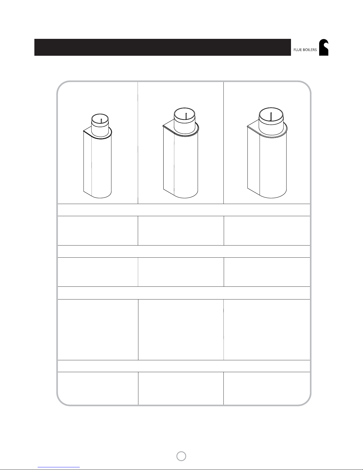
130mm (5in) FB100 150mm (6in) FB200 180mm (7in) FB300
Cove 1
Country 4
Cove 2
Island 1
Island 2
Country 6
Country 8
Country 12
Cove 3
Island 3
Average Water Heating Output:
1.8 kW 2.4 kW 3.4 kW
For use with the following stoves:
Nominal Size
Internal Diameter
130mm 155mm 183.7mm
FB100
FB200
FB300
®
charnwood
CHARNWOOD FLUE BOILERS
4
Page 5

The Charnwood Flue Boiler provides a means of heating water by
utilising some of the flue heat to provide domestic hot water and
some radiator heating. This is achieved by circulating water through a
jacket around the flue, whilst slowing the flue gases to transfer the
heat.
The boiler is bolted directly to the top of the stove and has two 1in
BSP connections for flow and return water pipes. The flue contains
boiler chains which cause turbulence in the flue gases and improve
the transfer of heat to the water.
Fumes from blocked flues can kill. Remove the access door and brush
off the chain hangers at least monthly. See ‘Maintenance’ section.
Do not light the stove without water in the system.
SAFETY WARNING
Do not light the stove if any part of the system is frozen.
There are some differences in operating the stove once a boiler has
been fitted. Before lighting ensure that all installation work has been
carried out according to these instructions, and that the chains and
the access door are securely fitted. Do not light the stove without
water in the system. It is important to allow time for the fire cement
to dry out before lighting - at least one day.
On initial lighting considerable condensation will be produced and this
will normally drip from the drip ring at the base of the boiler tube
onto the throatplate of the stove where it will evaporate. Some initial
sweating may occur at the joint between the boiler base and the flat
top of the stove, but this should cease after approx 2 hrs of
operating. If the sweating persists, this indicates an inadequate seal,
and the joint must be re-sealed. Start with a small fire and allow the
stove to heat up gradually so that the internal paint and fire cement
may cure evenly. When the stove and the boiler return pipe are both
hot, then all condensation should cease. When hot water is being
continuously used, then the stove should be well loaded and run at
such a rate that the return temperature does not fall below 40°C.
Once per month the access door must be unclipped and any soot
build up on the chain hangers brushed off with a small brush. Check
for any flue obstruction.
The chimney must be swept at least once per heating season, and the
boiler’s internal flue is cleaned at the same time. In order for this to
STOVE AND BOILER OPERATION
MAINTENANCE
Side Chain Hanger
Centre Chain
Hanger
Chains
Fig 1. Chain Access (access door removed)
happen, the boiler chains must first be removed. Ensure that the fire
is out and the stove is cold. Undo the clip on the back of the access
door, spring apart the two ends of the door and remove it from the
boiler. Unhook each of the chains from the hangers and allow them
to drop down onto the throatplate of the stove. Lift out the three
Chain Hangers. Remove the chains from above the throatplate, clean
them using a small brush The access door may now be replaced and
the chimney swept in the normal way through the stove. Remove the
access door again and and re-hang the chains on the hanger hooks.
When the hanger has had all its chains replaced, thread the lower
ends of the chains through the access opening, allow the ends to drop
down and manouevre the chain hanger back into its slots. It is easier
to replace the side hangers first, then the centre hanger. Replace the
access door and the stove is ready for re-lighting.
®
OPERATING INSTRUCTIONS
5
charnwood
Page 6

HEALTH AND SAFETY PRECAUTIONS
SYSTEM
Please take care when installing the boiler that the requirements of
the Health and Safety at Work Act 1974 are met.
Some types of fire cement are caustic and should not be allowed to
come into contact with the skin. In case of contact wash with plenty
of water.
If there is a possibility of disturbing any asbestos in the course of
installation then please use appropriate protective equipment.
In addition to these instructions the requirements of BS.8303 and
BS.6461 Pt 1&2; 1984 must be fulfilled. Local Authority Bylaws and
Building Regulations, including those referring to National and
European Standards regarding the installation of Solid Fuel burning
appliances, flues and chimneys must also be observed.
The Charnwood Flue Boiler is designed to be used with a Charnwood
stove. It can be used as a ‘stand alone’ heating system for domestic
hot water and/or radiators, or as part of a larger heating system.
There are a variety of ways in which it is possible to link up this boiler
with a larger system, and some of these are shown in Figs 2 to 4.
When a small stove such as the Cove 1 and a Flue Boiler FB100 are
used, a simple system as shown in Fig 2 may be used. A larger size of
hot water cylinder (i.e. above 115 Litres) is usually required to reduce
the possibility of boiling, since on this system no heat leak radiator is
shown. If the stove is to be run near its full capacity, then a heat leak
radiator should be considered.
If a larger stove such as the Island 3 and Flue Boiler FB300 are used,
then extra radiators may be added to the system as shown in Fig 3.
These are controlled by a high limit pipe thermostat mounted on the
This is particularly
necessary if the room is double glazed. It must be positioned such
that it is not liable to blockage.
Careful consideration must be given to the siting of the stove and
boiler, since the Boiler Access door MUST be accessible in order to
sweep the chimney. This means that there must be at least 750mm
free space above the top of the stove. The flow pipe connected to the
top of the boiler must rise continuously up to the vent. It must not
drop down and nominally horizontal runs should have some upward
slope.
!
There must be an adequate air supply into the room in which the
appliance is installed to provide combustion air. The combustion air
supply must be via a permanently open vent.
Domestic Hot
Water Draw Off
Drain Cock at Lowest Point
Drain Cock
Gravity Return 28mm
Gravity Flow 28mm
Indirect Hot Water Cylinder
Cold Water Tank
Overflow
Overflow
Feed and Expansion Tank
22mm Open Vents
Flue Boiler
Fig 2. Basic System Where Heat Leak Radiator
Is Not Required
Fig 3. Larger System With Heat Leak Radiator
Controlled By High Limit Pipe Thermostat
Radiator Return
Domestic Hot
Water Draw Off
Drain Cock at Lowest Point
Drain Cock
Gravity Return 28mm
Gravity Flow 28mm
Indirect Hot Water Cylinder
Cold Water Tank
Overflow
Overflow
Feed and Expansion Tank
22mm Open Vents
Radiator(s)
Circulating Pump
Injector Tee
Minimum Return
Thermostat
High Limit Pipe
Thermostat
Flue Boiler
®
INSTALLATION INSTRUCTIONS
6
charnwood
Page 7

gravity flow pipe, which gives priority to the domestic hot water, but
brings the pump on to heat the radiators when the flow pipe
temperature exceeds the set temperature. A minimum return pipe
thermostat will prevent cold water being pumped around the circuit
The stove and flue boiler may be installed as part of a larger system,
to provide back up or additional heat whilst the main boiler is not
operating. There are many ways in which this “Link Up” may be
achieved, and a basic link up system is shown in Fig 4. This uses a
“Dual Coil”cylinder. In this way the Flue Boiler is able to input heat
into the system without affecting the circulation in the other primary
coil(s). Similarly, if the other heat source is operating and the stove is
not lit, then there will be very little effect on the circulation through
the flue boiler. Additional controls such as an electronic timer may be
added in the “Link up” case if required and in some instances the
controls of the main boiler may be extended to control a pump in the
flue boiler circuit.
Fig 4. Basic Link Up system. Flue Boiler provides
input to existing system via Dual Coil Tank
Gravity Return (28mm Pipe)
Central Heating
Return
Common
Return to Boiler
(28mm Pipe)
Fig 5. Injector Tee as used in Fig 3 .
Domestic Hot
Water Draw Off
Drain Cock at Lowest Point
Drain Cock
Gravity Return 28mm
Gravity Flow 28mm
Dual Coil Hot
Water Cylinder
Cold Water Tank
Overflow
Overflow
Feed and Expansion Tank
22mm Open Vents
Heat Leak
Gravity Radiator
Flue Boiler
Additional Heat
source, e.g. oil or
gas boiler, solar
heating panel etc.
Fig 6. Free standing Installation
Double Insulated
Flue Pipe
Flue Connector
Flue Boiler
Stove
Hearth
Water
Flow
Water
Return
Access Door
Support Bracket
Fig 7. Horizontal Register Plate Into Conventional Chimney
Flue Boiler
Stove
Hearth
Water
Flow
Water
Return
Access Door
Register Plate
Soot Door
With Soot Door
Alternative
Positions
®
INSTALLATION INSTRUCTIONS
7
charnwood
Page 8

Sleeved Pipe
Soot Door
In Side or Rear
Of Chimney
Fig 8. Vertical Register Plate With Bricked Up Fireplace
Flue Boiler
Stove
Hearth
Access Door
Water
Flow
Water
Return
CHIMNEY, HEARTH & FIRE SURROUND
CONNECTIONS TO FLUES
Ensure that all the Instructions and Regulations contained in the
Charnwood Stove Installation Instructions are carried out and
adhered to. The Flue Boiler will limit the number of Flue Connection
options available, and three typical options are shown in Figs. 6 - 8.
There are several different ways of connecting the Flue, but in each
case the top flue outlet of the stove is used. The Flue Boiler is not
designed to use the rear flue outlet.
The adaptor is available from the Fluepipe
manufacturer. The double insulated flue must be supported by
brackets, and not rely on the boiler for its support, since this would
make removal of the boiler very difficult. The adaptor may require a
short piece of single wall stainless steel fluepipe to slide into the top
of the boiler.
A freestanding installation is shown in Fig 6 using double insulated
stainless steel fluepipe connected to the top of the boiler using a
short adaptor.
Fig 7 shows the flue connections into a standard chimney using a high
Sealing Face
Boiler Outer must be
pulled down onto stove
top using two M6 x 25mm
bolts and nuts.
Fig 9. Fitting& Sealing the Boiler to the Stove
level horizontal register plate. The minimum distance above the top
of the stove in this case is 800mm.
Fig 8 Utilises a 135° Bend to connect into the flue.
In each of these instances the chimney may be swept through the
stove.
spread
attach
INSTALLATION
First remove the top blanking plate of the stove and fire
cement evenly on the sealing face. Lower the boiler into position as
shown in Fig 9. Align the boiler fixing tags with the flue ring tags on
the stove, and insert the two M6 x 25mm bolts, their nuts and
tighten until the outer lower edge of the boiler is drawn firmly into
contact with the top of the stove. Remove excess fire cement which
has squeezed out of the joint . It is essential that this joint is well made
to prevent condensation escaping from the boiler / stove interface.
Slide the adaptor up until its inner diameter is aligned with the flue
boiler and lower it down into the top of the Flue Boiler and seal the
joint with fire cement.
When the Stove, Boiler and Fluepipe have all been fixed in position,
remove the access door and check the position and location of the
chains and hangers since these are held in by gravity and may have
come out during installation. Replace the Access door and clip firmly
together.
Connect the 28mm diameter flow and return water pipes to the
1inch BSP fittings on the back of the boiler using brass compression
fittings and ensure that the flow pipe (top) rises continuously to the
vent. Fill the system with water + antifreeze + corrosion inhibitor as
required and check for leaks.
®
INSTALLATION INSTRUCTIONS
8
charnwood
Page 9

FB100
450
132.5
109
621
124
140
190
8
BACK VIEW
194
606
SIDE VIEW
130
98.5
8
TOP VIEW
Internal Dia
FB200
621
211
450
130
124
132.5
8
165
131
155
9
TOP VIEW
237
606
BACK VIEW
SIDE VIEW
Internal Diameter
FB300
450
621
160
250
132.5
8
193.7
124
146
183.7
12
TOP VIEW
606
BACK VIEW
271
SIDE VIEW
Internal Diameter
COMMISSIONING
On completion of the installation and after allowing a suitable period
of time for the fire cement and mortar to dry out, light the stove and
check to ensure that smoke and fumes are taken from the appliance
up the chimney and emitted safely. Also check all joints and seals for
soundness.
Adjust the central heating pump (if fitted) to give the correct water
flow against the circuit resistance and balance the system correctly.
On completion of the installation and commissioning please leave the
operating instructions with the customer and advise on the use of the
appliance and any controls on the system.
®
INSTALLATION INSTRUCTIONS
9
charnwood
Page 10

Issue B
6
5
1
3
4
3
2
FB100
FB200
1
5
6
3
4
2
3
FB300
Item Part No. Description
1 010/FB100/## Flue Boiler 130mm
2 006/FB112 Boiler Chain Length
3 010/FB107 2 Hook Hanger
4 010/FB207 3 Hook Hanger
5 004/FB113 Top Cover Plate
6 004/FB108 Access Door
Item Part No. Description
1 010/FB200 Flue Boiler 150mm
2 006/FB112 Boiler Chain Length
3 010/FB207 3 Hook Hanger
4 010/FB306 4 Hook Hanger
5 004/FB213 Top Cover Plate
6 004/FB208 Access Door
Item Part No. Description
1 010/FB300/## Flue Boiler 180mm
2 006/FB112 Boiler Chain Length
3 010/FB306 4 Hook Hanger
4 010/FB307 5 Hook Hanger
5 004/FB313 Top Cover Plate
6 004/FB308 Access Door
To obtain spare parts please contact your local stockist giving Model,
Part No. and Description. In case of difficulty contact the
manufacturer at the address shown.
4
1
6
5
3
2
3
®
FLUE BOILERS PARTS LIST
®
charnwood BI SHO P S WAY, NEW PORT, IS LE OF WI GHT P O30 5WS, UN ITE D KING DOM
T:+44 (0)1983 537799 • F:+44 (0)1983 537788 • SPARES@CHARNWOOD.COM • WWW.CHARNWOOD.COM
charnwood
10
charnwood
Page 11

CHARNWOOD FLUE BOILER GUARANTEE
Your Charnwood Flue Boiler is guaranteed against material and
manufacturing defect for a period of 1 year from date of purchase.
The following conditions apply:
?
?
?
?
?
?
?
?
If any part fails due to manufacturing or material defect within the
guarantee period Charnwood will, free of charge, either repair or
replace the part at their discretion. The decision of Charnwood is
final.
This guarantee is for parts and labour only.
Consumable items such as rope seal and associated parts are not
included.
Charnwood will not be liable for any consequential loss or
incidental loss, damage or injury however caused.
This guarantee will become void if the appliance: is not installed in
accordance with the installation instructions; is not regularly
serviced, in accordance with the installation instructions; is subject
to misuse or neglect, including the use of non-recommended fuel
or operation without water in the boiler; is used on stoves other
than those manufactured by Charnwood; or if repairs or
modifications have been carried out by anyone other than
Charnwood or their official representatives.
All claims on this guarantee must be made through the supplier of
the appliance and must be accompanied by proof of purchase.
Nothing in this guarantee shall affect your statutory rights.
This guarantee is applicable in the UK, Ireland and France.
®
GUARANTEE
11
charnwood
Page 12

A D i v i s i o n o f A . J . W e l l s & S o n s L i m i t e d R e g i s t e r e d i n E n g l a n d N o . 0 3 8 0 9 3 7 1
charnwood BI SHO P S WAY, NEW PORT, IS LE OF WI GHT P O30 5WS, UN ITE D KING DOM
T:+44 (0)1983 537777 • F:+44 (0)1983 537788 • CONTACT US AT WWW.CHARNWOOD.COM
charnwood
y ou r p re m ie r de a l e r
REV. FB 11.08
®
 Loading...