

Page 1
®
charnwood
BAY 5
Operating & Installation Instructions
Page 2

Page 3

C O N T E N T S
OPE R AT I NG IN S TRUC T ION S
Quick Guide 4
General
Fuel 5
Door Operation 5
Ash Clearance 5
Controlling the Fire 5
Lighting 6
Refuelling 7
Reduced Burning 7
Cleaning and Maintenance 7
Throat Plate and Flueway Cleaning 7
Chimney Sweeping 8
CO Alarm 8
Troubleshooting 9
If you need further help 9
INSTALLATION INSTRUCTIONS
5
Health and Safety Precautions 10
Air Supply 10
CO Alarms 10
Chimney 10
Specification 10
Hearth and Fire Surround 11
Preparation of Fireplace 11
Fitting the Stove and Flue Pipe 12-14
Pre-lighting Check 15
Commissioning 15
CAA and Smoke Control 15
Dimensions 16
Parts Lists 17
Certification 18
Ref. BAY 5 v3 1.14
Page 4
QUICK GUIDE
Glass
Wipe with a damp, lint free
cloth. Any stubborn deposits
may be removed with a
proprietary stove glass cleaner
or ceramic hob cleaner.
Throat
plate
Take down once a week and
clean. Sweep sooty deposits
into fire.
Ash
removal
For best wood burning, leave a
layer of ash 1cm thick on base
of stove. If ash gets thicker than
this, remove excess with scoop
provided
Chimney
Have chimney swept twice a
year. Chimney can be swept
through stove
Servicing
Stove should be serviced by a
professional at least once a
year
b
d
e
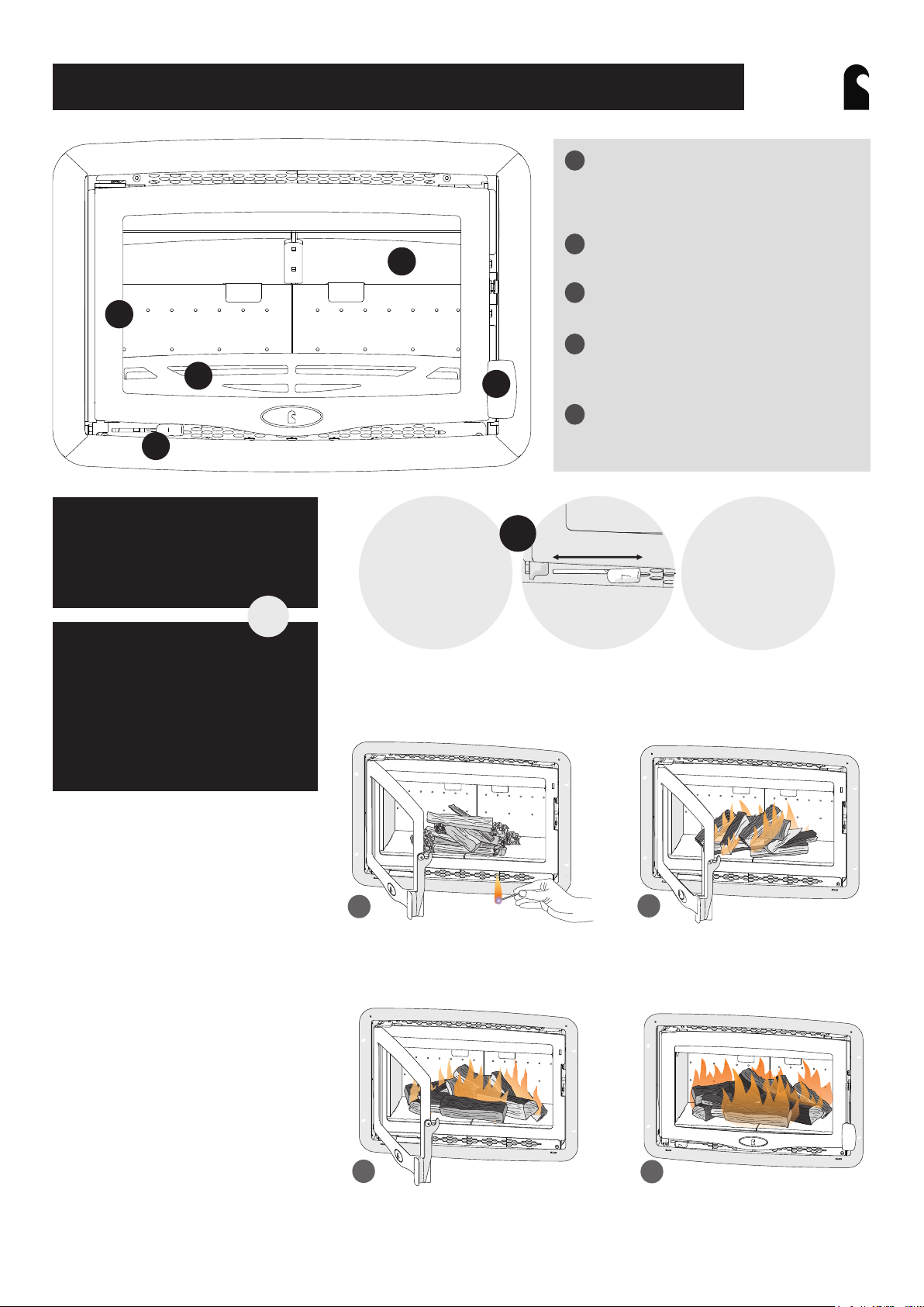
Your Charnwood at a glance
a
ch ar nw ood
BAY
Throat plate
a
Improves efficiency of stove by slowing
down flue gases. See page 8 for how to
remove
Door
b
Keep closed while stove is in use
c
Door handle
Pull up to open
d
Fuel retainer
Ensure fuel does not protrude beyond
c
retainer
e
Air control
Slide left for higher output. See page 5 for
more detail
®
Suitable fuels for your
Charnwood:
This stove is designed to burn
only wood.
p5
Unsuitable fuels:
Smokeless fuels
Petroleum coke
Liquid fuel
Household waste
Coal singles
Wet or unseasoned wood
MAINTENANCE AND CLEANING
Air control
1. Slumber
p5
1
34
2
2. Medium output
3. High output
4. Boost
Bay 5
Fig. 1 Air control
LIGHTING AND CONTROLLING THE FIRE
See page 6 for more details
1
Add initial kindling and paper or
firelighters. Set air control to ‘boost’ and
close the door.
2
Once kindling is alight, add smaller logs.
Keep air control at maximum.
FOR
TROUBLE-
SHOOTING,
SEE PAGE 9
3
Add larger logs to the required fuel load
once flames are established.
4
Once long flames appear, reduce the air
control to high. Reduce again to medium
depending on type of burn required.
Page 5
OPERATING INSTRUCTIONS
ch ar nw ood
BAY
®
GENERAL
Before lighting the stove, check with the installer that the work and
checks described in the Installation Instructions have been carried out
correctly and that the chimney has been swept, is sound and free
from any obstructions. The stove is not suitable for use in a shared
flue system.
Remember that the stove will be hot and that it is made from hard
materials – ensure that you have good balance before operating the
fire.
Do not use an aerosol spray on or near the stove when it is alight.
There is a risk of explosion or flash ignition of the spray.
When using the stove in situations where children, aged and/or
infirm persons are present a fireguard must be used to prevent
accidental contact with the stove. The fireguard should be
manufactured in accordance with BS 8423:2002.
The stove is suitable for intermittent operation.
FUEL
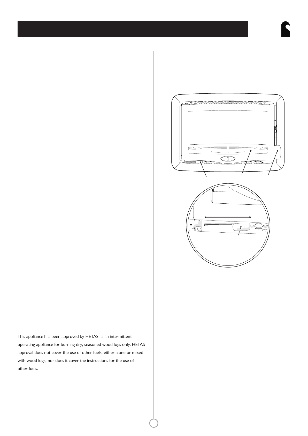
gloves provided may be required.
Take care not to touch the doors as they will be hot when the fire is
burning. Pull the door handle up to open, and push down to close.
The stove should be run with the door shut.
Fig. 1 Stove controls
Fig. 2 Air control
Air control
Fuel retainer
Door handle
Only dry, well seasoned wood should be burnt on this appliance as
burning wet, unseasoned wood will give rise to heavy tar deposits in
the stove, on the glass and within the chimney. For the same reason
hard woods (such as Ash, Beech and Oak) are better than soft woods
(such as Pine and Spruce). Burning wet, unseasoned wood will also
result in considerably reduced outputs. The wood should be cut and
split and then left to season in a well ventilated dry place for at least
one year, but preferably two years, before use, and should have a
moisture content of less than 20%. Logs should be no more than
480mm long and 75mm wide.
PETROLEUM COKE IS NOT SUITABLE FOR USE ON THIS
APPLIANCE. ITS USE WILL INVALIDATE THE GUARANTEE.
This stove is not designed to burn household waste. For advice on
other fuels, please contact Charnwood.
This appliance has been approved by HETAS as an intermittent
operating appliance for burning dry, seasoned wood logs only. HETAS
approval does not cover the use of other fuels, either alone or mixed
with wood logs, nor does it cover the instructions for the use of
other fuels.
DOOR OPERATION
34
1
2
Air control handle
1. Slumber
2. Medium Output
3. High Output
4. Boost
ASH CLEARANCE
For optimum wood burning, it is important to leave a layer of ash,
around 1cm thick, on the base of the stove. If the ash is becoming
too deep, the top layer of ash should be cleared using the scoop
provided.
CONTROLLING THE FIRE
The rate of burning and hence the output is controlled by the air
control (see Fig. 2).
Open the air control fully when lighting or when rapid burning is
required. It should not be left fully open for long periods as this can
cause over-firing or excessive smoke production. For high output
move the air control to the ‘High Output’ position’ or for low
burning to the fully closed position.
The door handle has been carefully designed so that in normal use it
may be operated using bare hands. However, if you need to open the
doors when the fire is running at maximum, then the use of the
When the fire is burning normally the air control gives enough
airwash to keep the glass clean. However, it will not always be
possible to keep the glass clean with the air control fully closed.
5
Page 6
OPERATING INSTRUCTIONS
ch ar nw ood
BAY
®
LIGHTING
On initial lighting, the stove may smoke and give off an odour as the
silicon paint with which the firebox is painted reacts to the heat. This
is normal and will cease after a short time, but meanwhile the room
should be kept well ventilated.
At first only light a small fire and burn it slowly for two hours to allow
any residual moisture in the chimney to evaporate.
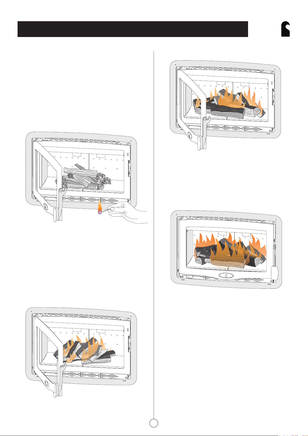
Fig. 3 Initial firing
Fig. 5 Adding larger logs
When the flames are established around the smaller logs, load the
stove with larger logs to the required fuel load. Logs should be no
more than 75mm in diameter and 480mm long. Maximum filling level
is such that logs cannot fall from the fire when the door is opened.
Close the door. Maintain the air control at maximum at this stage.
Fig. 6 Fire well underway
Light the stove using dry kindling wood and paper or fire lighters. It is
recommended that you use approximately 1kg to 1.2kg of kindling.
Put the paper, or fire lighters, and kindling in the firebox and cover
with a few small dry logs. Open the air control fully (see Fig. 2). Light
the paper or fire lighters. The door may be left cracked open for a
few minutes to assist the combustion and heat up the firebox more
quickly. NB The diagrams are shown without the front fence for ease
of viewing. Front fence must be fitted when lighting a fire.
Fig. 4 Building up the fire
Once long flames appear over the fire, reduce the air control to the
‘high output’ setting. Once the fire is well established - with each log
alight at the top - the air setting can be reduced again, depending on
the type of fire required. If at any stage the flames start to go out or
the glass begins to discolour, a higher setting is required. To achieve
this, push the air control back to the left to re-establish a consistent
burn.
Once the fire is up to temperature the airwash system will begin to
work, so allow the fire to become hot before adjusting the air control
to the required setting. During the lighting period, do not leave the
stove unattended. Do not leave the door open except as directed
above to avoid excessive smoke.
When the kindling wood is well alight add a few more small logs and
close the door, but leave the air control fully open.
When relighting the stove, leave the ash on the base unless it is
becoming too deep, in which case some of it may be removed.
6
Page 7

OPERATING INSTRUCTIONS
ch ar nw ood
BAY
®
REFUELLING
Keep the firebox well filled but do not allow fuel to spill over the top
of the fuel retainer.
Logs should be evenly distributed, filling the firebed to give the most
pleasing flame pattern. The air control must be fully opened after
refuelling until the flames are established above the fire. It is best to
refuel on to a hot bed of ash. If at this point the fire starts to die, the
door must be cracked open until the fire is revived. If the fire has
started to die down before refuelling, then more kindling wood must
be added, the air control opened fully and the door cracked open to
re-establish the firebed before adding larger logs (see suitable log
sizes in Specification section). This will avoid excessive smoke
emission.
Care should be taken that wood does not project over the fuel
retainer or damage to the glass may be caused when the door is
closed. It can also cause the glass blackening of the glass. Maximum
filling height is such that logs cannot fall from the fire when the door
is opened. In smoke controlled areas do not fill the stove above the
level of the air holes in the back bricks, as overloading can cause
excess smoke. Liquid fuels are not to be used on this appliance.
it to cool. Clean the glass using a damp cloth and then wiping over
with a dry cloth. Any stubborn deposits on the glass may be removed
with a proprietary stove glass cleaner or ceramic hob cleaner.
Aerosol spray cleaners must not be used near the appliance whilst it
is under fire.
Do not use abrasive cleaners or pads as these can scratch the surface
which will weaken the glass and cause premature failure.
When Not in Use
If the fire is going to be out of use for a long period (for instance in
the summer) then to prevent condensation, and hence corrosion, the
air control should be left fully open and the fire door left ajar. It Is
also advisable to sweep the chimney and clean out the fire. Spraying
the inside of the door and firebox with a light oil, such as WD40, will
also help to keep all internal parts working well.
where the fire has been out of use, the chimney and appliance
flueways should be cleaned before lighting.
After long periods
Door Seals
For the fire to operate correctly it is important that the door seals
are in good condition. Check that they do not become worn or
frayed and replace them when necessary.
REDUCED BURNING
For reduced burning the fire door must be closed.
When burning wood in areas that are not smoke controlled, load
some large logs on the fire and allow to burn for half an hour before
closing the air control (this will help to reduce tar deposits in the
chimney). Some experimentation may be necessary to find the setting
most suitable for the type of fuel being used and the draw on the
chimney.
CLEANING AND MAINTENANCE
Cleaning
The stove is finished with a high temperature paint which will
withstand the temperatures encountered in normal use. This may be
cleaned with a damp lint-free cloth when the stove is cold. Should repainting become necessary, high temperature paints are available
from your supplier or from stove shops, or in case of difficulty,
directly from Charnwood.
Cleaning the Glass
The glass in the door is a special ceramic glass which is able to
withstand high temperatures. Most deposits on the glass may be
burnt off simply by running the fire at a fast rate for a few minutes. If
it becomes necessary to clean the glass then open the door and allow
Servicing
It is recommended that the fire is serviced once a year to keep it in
first class working order. After cleaning out the firebox thoroughly,
check that all internal parts are in good working order, replacing any
parts that are beginning to show signs of wear. Check that the doors
seals are in good condition and that the door seals correctly.
A servicing guide is available on request. Repairs or modifications
may only be carried out by the Manufacturer or their approved
agents. Use only genuine Charnwood replacement parts.
THROAT PLATE AND
FLUEWAY CLEANING
It is important that the throat plate and all the stove flueways are kept
clean in order to prevent potentially dangerous fume emission. Check
by looking up into the firebox for signs of soot or fly-ash on the
throat plate and sides of the firebox. If there are signs of a build up of
soot or fly-ash then cleaning is necessary. Cleaning should occur at
least once a month and more frequently if required. Let the fire out
and ensure it is cold before carrying out these operations. If
necessary, wear your Charnwood gloves to prevent irritation from
soot deposits.
The throat plate consists of two firebrick panels which rest on the
central bracket and the two side bricks. To lower, push the brick up
7
Page 8

OPERATING INSTRUCTIONS
ch ar nw ood
BAY
®
towards the topmost corner of the stove, and lower down diagonally
(see Fig. 7). Any sooty deposits should then be swept from the plate
and into the fire.
Return the throat plates to their correct position by reversing the
above method, ensuring they slot onto the bracket and rest securely
on the side panels.
CHIMNEY SWEEPING
The chimney should be swept at least twice a year. It will generally be
possible to sweep the chimney through the appliance. If the stove is
fitted in place of an open fire, the chimney should be swept one
month after installation to clear any soot falls which may have
occurred due to the difference in combustion between the stove and
the open fire.
First remove the fuel retainer and the throat plate. Then sweep the
chimney ensuring that soot is removed from all horizontal surfaces
after sweeping.
In situations where it is not possible to sweep through the appliance
the installer will have provided alternative means, such as a soot door.
After sweeping the chimney the appliance flue outlet and the flue
pipe connecting the stove to the chimney must be cleaned with a flue
brush.
Fig. 7 Throat plate position and lowering
Push upwards
towards corner
and rotate down
2
1
Front view
Throat plate
Bracket
Throat plate
Side brick
After clearing any soot from within the stove, replace the throat plate
(see Fig. 7) and the fuel retainer.
Different types of sweep’s brushes are available to suit different
flueways. For standard brick chimneys, a wire centre sweep’s brush
fitted with a guide wheel is recommended. For prefabricated
insulated chimneys the manufacturers instructions with regard to
sweeping should be consulted.
CO ALARM
Your installer should have fitted a CO alarm in the same room as the
appliance. If the alarm sounds unexpectedly, follow the instructions
given under “Warning Note” overleaf.
Side View
8
Page 9

TROUBLESHOOTING
ch ar nw ood
BAY
®
FIRE WILL NOT BURN
Check that:
a) the air inlet is not obstructed in any way,
b) chimneys and flueways are clear,
c) a suitable fuel is being used,
d) there is an adequate air supply into the room,
e) an extractor fan is not fitted in the same room as the stove.
f) there is sufficient draw in the chimney. Once the chimney is warm a
draught reading of at least 1.3 mm (0.05 inches) water gauge
(12.5Pa) should be obtained.
BLACKENING OF DOOR GLASS
Differences in chimney draughts mean that the best settings of the air
controls will vary for different installations. A certain amount of
experimentation may be required, however the following points
should be noted and with a little care should enable the glass to be
kept clean in most situations:
a) Wet or unseasoned wood, or logs overhanging the front fence will
cause the glass to blacken.
b) The airwash relies on a supply of heated air to keep the glass clean.
Therefore, when lighting the stove, allow the firebed to become well
established before closing the air control. This may also be necessary
when re-fuelling the stove.
c) When re-fuelling keep the fuel as far back from the front fence as
possible. Do not try to fit too much fuel into the firebox.
d) Do not completely close the air control.
It is always more difficult to keep the glass clean when running the
stove very slowly for long periods.
FUME EMISSION
Warning Note:
Properly installed and operated this appliance will not emit fumes.
Occasional fumes from de-ashing and re-fuelling may occur.
Persistent fume emission is potentially dangerous and must not be
tolerated. If fume emission does persist, then the following
immediate actions should be taken:
a) Open doors and windows to ventilate the room.
b) Let the fire out and safely dispose of the fuel from the
appliance.
c) Check for flue or chimney blockage, and clean if required.
d) Do not attempt to re-light the fire until cause of fume has been
identified. If necessary, seek professional advice.
The most common cause of fume emission is flueway or chimney
blockage. For your own safety these must be kept clean.
CHIMNEY FIRES
If the chimney is thoroughly and regularly swept, chimney fires should
not occur. However, if a chimney fire does occur close the air control,
and tightly close the door of the appliance. This should cause the
chimney fire to go out in which case the controls should be kept
closed until the stove has gone out. The chimney and flueways should
then be cleaned. If the chimney fire does not go out when the above
action is taken then the fire brigade should be called immediately.
After a chimney fire the chimney should be carefully examined for
any damage. Expert advice should be sought if necessary.
IF YOU NEED FURTHER HELP
If blackening of the glass still occurs check that all flue connections
and the blanking plate are well sealed. It is also important that the
chimney draw is sufficient and that it is not affected by down-draught.
When the chimney is warm a draught reading of at least 1.3 mm
(0.05 inches) water gauge (12.5Pa) should be obtained. Some
blackening of the glass may occur below the level of the fuel retainer.
This will not obscure the view of the fire or affect its performance.
FIRE BLAZING OUT OF CONTROL
Check that:
a) The door is tightly closed.
b) The air control is fully closed.
c) A suitable fuel is being used.
d) Door seals and airwash slide are intact.
If you need further help with your Charnwood then your Installer will
be able to provide the answers to most questions. Your Local
Charnwood Premier Dealer has a great deal of experience and will
also be able to provide helpful advice. Further help is available from
the Charnwood Customer Services department who will be pleased
to give advice, if necessary.
9
Page 10

INSTALLATION INSTRUCTIONS
SPECIFICATION
Output
5kw (BTU/h)
Mass
94.3kg
Flue Gas Temperature
279°C
Flue Gas Mass Flow
4.1g/s
Average Refuelling Cycle
0.75hrs
Maximum Log Size Length 480mm
Diameter 75mm
Outputs were achieved burning seasoned hardwood logs over a 45 minute
refuelling period
ch ar nw ood
BAY
®
HEALTH AND SAFETY PRECAUTIONS
Please take care when installing the stove that the requirements of
the Health and Safety at Work Act 1974 are met.
Some types of fire cement are caustic and should not be allowed to
come into contact with the skin. In case of contact, wash with plenty
of water.
If there is a possibility of disturbing any asbestos in the course of
installation then please use appropriate protective equipment.
There must not be an extractor fan fitted in the same room as the
stove as this can cause the appliance to emit fumes into the room.
As the output is below 5kW a permanent air supply is not normally
required. This stove is capable of intermittent operation.
This stove is not suitable for use in a shared flue system.
In addition to these instructions the requirements of BS 8303 and
BSEN 15287-1:2007 must be fulfilled. Local Authority Bylaws and
Building Regulations, including those referring to national and
European Standards, regarding the installation of Solid Fuel burning
appliances, flues and chimneys must also be observed.
AIR SUPPLY
The air supply kit provided with the stove supplies sufficient
combustion air for use in a house with a designed air permeability of
more than 5m³/(h.m²). A spillage test must be carried out during
commissioning to verify adequate supply to the room.
The external air kit must be fitted to allow a flow of air to enter the
stove.
CO ALARMS
Building regulations require that whenever a new or replacement
fixed solid fuel or wood/biomass appliance is installed in a dwelling a
carbon monoxide alarm must be fitted in the same room as the
appliance. Further guidance on the installation of the carbon
monoxide alarm is available in BS EN 50292:2002 and from the
alarm manufacturer's instructions. Provision of an alarm must not be
considered a substitute for either installing the appliance correctly or
ensuring regular servicing and maintenance of the appliance and
chimney system.
CHIMNEY
In order for the appliance to perform satisfactorily the chimney
height must not be less than 4 metres measured vertically from the
outlet of the stove to the top of the chimney. The internal dimensions
of the chimney should preferably be 175mm (7 inches) or 200mm (8
inches) either square or round and MUST NOT BE LESS THAN 150
mm (6 inches).
If an existing chimney is to be used it must be swept and checked, it
must be in good condition, free from cracks and blockages, and
should not have an excessive cross sectional area. If you find that the
chimney is in poor condition then expert advice should be sought
regarding the necessity of having the chimney lined. If it is found
necessary to line the chimney then a lining suitable for Solid Fuel must
be used.
If the stove has been fitted in the place of an open fire, it is
recommended that the chimney is swept one month after installation
to clear any soot falls which may have occurred due to the difference
in combustion between the stove and the open fire.
If there is no existing chimney then a prefabricated block chimney or
a twin walled insulated stainless steel flue to BSEN 15287-1:2007 can
be used either internally or externally. These chimneys must be fitted
in accordance with the manufacturers instructions and Building
Regulations.
Single wall flue pipe is suitable for connecting the stove to the
chimney but is not suitable for using for the complete chimney.
It is important that there is sufficient draw in the chimney and that
the chimney does not suffer from down-draught. When the chimney
is warm the draw should be not less than 1.3mm (0.05 inches) water
gauge (12.5 Pa). If it is found that there is excessive draw in the
chimney then a draught stabiliser should be fitted. If in doubt about
the chimney seek expert advice.
10
Page 11

INSTALLATION INSTRUCTIONS
ch ar nw ood
BAY
®
Fig. 8 Minimum Distances from Combustibles
Mantelpiece
D
Dimension A: 190mm
Dimension B: 300mm
Dimension C: 900mm
Dimension D: 350mm
A
C
From centre of
glass into room
B
A
Hearth
HEARTH AND FIRE SURROUND
The stove must be installed above a fireproof hearth and must be
situated at least 300mm (12 inches) from any combustible material
unless adequately fireproofed in accordance with local building
regulations (See Fig. 8)
the hearth are governed by building regulations for Class 1
appliances. If in doubt as to the positioning of the stove expert advice
should be sought either from the supplier or the local building
inspector.
. The positioning of the stove and the size of
Fig. 10 Limiting Dimensions of Surround and Opening
700mm
A
B
The shaded grey area on the face of the surround is
the minimum flat area required for inset installation.
Dimension A:
Min. 615mm
Max. 650mm
Dimension B:
Min. 410mm
Max. 440mm
600mm
C
Dimension C:
Min. 380mm
PREPARATION OF FIREPLACE
Before fitting the appliance into an existing fireplace remove the
fireback and any loose in-fill material.
If a wooden mantelpiece or beam is used in the fireplace it should be
a minimum of 350mm (14 inches) from the appliance. In some
situations it may be necessary to shield the beam or mantelpiece to
protect it.
In order for the appliance to fit into the fire surround there must be a
flat area around the opening. Details are shown in Fig. 10.
Fig. 9 Air vents and insulation in a fireplace containing combustible
materials
Ø80mm air vent through insulation and wall of fireplace
80mm Calcium
silicate board
100mm air gap
(2 per side)
Top of stove
Fireplace
If the fireplace contains combustible materials, two air vents of 80mm
diameter must be fitted through the insulation and the wall of the
fireplace to provide a continual air flow around the stove (Fig. 9).
Similar vents must be placed between the closure plate and the top of
the stove to ventilate the cavity. It is recommended that 80mm
Calcium Silicate board is used, with a 100mm air gap between the
stove and the insulation.
The surround and opening for the appliance must conform with
Fig.10. The flat area around the opening should be a minimum of
700mm wide and 600mm high. Ensure that the hearth and the base
in the opening are flat, level, and at right angles to the surround.
Fig. 11 Installation in a standard chimney
Closure plate
Flexible flue liner
Vermiculite infill
Pour down from
top of chimney
Lintel
Stove
External air kit
to outside wall
11
Page 12

INSTALLATION INSTRUCTIONS
ch ar nw ood
BAY
®
1. Attach flue collar to length of flexible flue liner
Flexible flue liner
Fix collar to flue with
screws either side
Upper flue collar
Collar can be positioned as necessary
depending on required angle of flue
Self-clinching studs
2. Insert convection casing into opening
External air supply
FITTING THE CONVECTION CASING,
STOVE AND FLUE PIPE
It is recommended to have a layer of insulation between the casing
and the outer wall. This may consist of a layer of mineral fibre or a
vermiculite concrete mix (see Step 4). If rockwool is being used,
insert this into the opening before sliding in the convection casing.
1. ATTACH FLUE COLLAR TO THE FLUE PIPE
It is recommended to use a flue liner with a length of flexible flue
pipe. Fix the upper flue collar to the flue pipe through the screw
holes in the side of the ring. The flue collar can be attached at any
angle depending on the required angle of the flue.
It is vital that the connections at both ends of the flue pipe are well
sealed. The flue pipe and collar can be sealed with fire cement and/or
a gasket. A closure plate should be used at the top end of the flue
pipe.
Once the collar is attached, push the flue pipe and flue collar up out
of the way for the casing to be inserted.
Convection casing
2. INSERT THE CONVECTION CASING INTO THE OPENING
3. MAKE FLUE CONNECTION
Reaching through the flue outlet, pull the flue collar down through
the outlet until the studs line up with the four holes in the convection
casing. Use nuts to secure the studs into place.
Flue pipe
Sealed with gasket
Upper flue collar
Make sure the three self-clinching studs are in the holes in the flue
collar, pointing downwards. Slide the convection casing into position
in the opening until the flue outlet lines up with the flue pipe.
Line up studs with holes
in convection casing
Secure stud with nut
Convection casing
12
Page 13

INSTALLATION INSTRUCTIONS
4. SECURE THE CASING TO THE WALL
Secure the casing in the opening by inserting screws, as shown on the
diagram. The stove can be screwed down through the base or through
the sides as required.
5. FILL WITH INSULATION AND MAKE GOOD THE OPENINGS
If you are using the vermiculite method of insulating the convection
casing, pour down from the top of the chimney. Fill in the space between
the casing and the brickwork and around the flue pipe with a vermiculite
or perlite concrete mix (see fig. 11). The recommended mixture is 6
parts of vermiculite or perlite to 1 part cement. Add only enough water
so that a few drops are released when a handful of the mixture is
squeezed.
Make good the opening at the top and sides of the convection casing
ensuring that a good seal is made with the side flanges. It is
recommended to use heat resistant plaster on the wall surrounding the
stove.
ch ar nw ood
BAY
Attach convection casing to wall by
inserting screws at any of these points
®
If for any reason it is not going to be possible to sweep the chimney
through the appliance, a soot door must be fitted.
6. SLIDE IN THE STOVE
Carefully slide the stove into the convection casing until the flue outlet
lines up with the upper flue collar and the air inlet engages at the base of
the stove.
7. INSERT COACH BOLTS
From the inside of the stove, insert coach
bolts in to slots A and B so that they hang
down into the stove. These are held in
place by the clips and will secure the flue
collar.
B
A
Slide the stove into position along the rollers
13
Washer
M8x17
‘R’ Pin
1.7mm
Roller
Clevis Pin
(welded inside
stove)
ATTACHING THE
ROLLERS
Slot the roller and
washer over the clevis
pin. Insert ‘R’ pin
through the clevis pin.
Page 14

INSTALLATION INSTRUCTIONS
8. SECURE THE FLUE ADAPTORS
Working through the stove, line up the inner flue collar to meet
the upper flue collar, carefully easing the ends of the coach bolts
through the holes. Fit the nuts onto the ends of the coach bolts and
tighten.
Check that the flue pipe is not obstructed or restricted in any way
and that all joints are well sealed.
Flue pipe
Upper flue collar
ch ar nw ood
BAY
Convection casing
®
Sealed with 8mm
self-adhesive rope seal
Inner flue collar
Wall of stove
Secure with nut here
9. ATTACH THE FRAME
Finally, fit the frame to the front of the stove.
First, hold the top and bottom pieces in place.
The two side panels fit onto the top and
bottom pieces and hold the frame together.
Slot into position and screw into place with a
countersunk screw, as shown in the diagram
below.
14
Top frame
Side
frame
Page 15

INSTALLATION INSTRUCTIONS
ch ar nw ood
BAY
®
Fig. 12 Fitting the optional base assembly
Top Trim Piece
Convection Casing
Side Trim Piece
M8x20 Screws
Base
Assembly
M8 Nut
Lower fireplace trim
FITTING THE OPTIONAL BASE
3. Check that the front fence is fitted correctly and that the door
closes properly.
COMMISSIONING
On completion of the installation allow a suitable period of time for
the fire cement and mortar to dry out before lighting the fire. Check
to ensure that smoke and fumes are taken from the appliance up the
chimney and emitted safely. Also check all joints and seals. On
completion of the installation and commissioning please leave the
operating instructions with the customer and advise them on the use
of the appliance.
M8x10
Screws
ASSEMBLY
1. With the firebox removed, roll the outer convection casing onto its
back and fasten the assembly into position using four M8x20 screws
and nuts. Insert the screws through the holes in the underside of the
casing from the inside and fit the nuts onto the outside of the base.
Do not fully tighten the screws at this stage.
2. Attach the lower fireplace trim into position onto the base frame.
This part replaces the lower trim piece (002/MR113). Use two
M8x10 screws and finger tighten them to allow adjustment.
3. Trial fit the side trim pieces (002/XR112) and adjust the lower
fireplace trim position to obtain a good fit. Once everything is
aligned, tighten all fasteners.
4. Undo the foot adjustment screws on the base assembly so that
they are just below the lower level of the base frame. Stand the
whole assembly up onto the base and trial fit into the fireplace
opening. Adjust the feet to overcome and rocking, should the
fireplace floor be uneven.
PRE LIGHTING CHECK
Before initial lighting check the following points:
1. The side firebricks, back firebricks and base plates must be in
position and sitting correctly.
2. The throat plate must be fitted in the roof of the appliance (as
shown in Fig. 8).
15
Page 16

Bay 5 DIMENSIONS (mm)
685
ch ar nw ood
BAY
®
495
350
FRONT VIEW
350
235
120
610
BACK VIEW
ø158
(for a 6" flue)
412
ø100
70
70
SIDE VIEW
NB: Door extends a maximum of 573mm
from front of stove when open.
FRONT VIEW WITH FIREPLACE TRIM
85
PLAN VIEW
599
16
Page 17

Bay 5 PARTS LIST
Issue A
ch ar nw ood
BAY
55
42
41
40
46
54
13
56
14
®
31
32
39
26
25
19
18
20
21
22
Item Part No Description
1 001/XR010 Firebox
2# 002/XR001/A Door Assembly
3 006/MR019 Glass
4 008/MR047 Handle Pivot Boss
5 004/XR074 Glass Retainer
6* 008/XR075 Glass Seal
7* 008/XR076 Door Seal
8 008/FFS046 M6x20 CSK Allen Screw
9 008/FFW027 M10 Wavy Washer
10 008/FFW007 M10x19 Washer
11 008/MR088 Handle
12 010/MR012 Handle Plate
13 011/MR031 RH Baffle Firebrick
14 011/MR032 LH Baffle Firebrick
15 011/MR033 RH Side Firebrick
16 011/MR028 LH Side Firebrick
17 004/XR055 Air Slide Cover
18 008/XR063 Air Box Upper Gasket
19 004/XR007 Air Control Slider
20 004/XR064 Control Rod
21 010/XR022 Air Slide Control Handle
22 004/XR058 Clicker Assy
23 008/XR062 Airbox Lower Gasket
24 008/XR012 Control Knob
25 004/XR072 Air Control Plate
26 008/XR073 Air Control Gasket
27 011/XR029 LH Base Firebrick
28 011/XR031 RH Base Firebrick
16
23
24
1
5
37
53 3635
50 49 51
28
27
43
17
48
47
Item Part No Description
29 004/MR044 Latch Plate
30 002/XR020 Lower Hinge Bracket
31 010/XR011 Convection Casing
32 004/MR060 Air Duct Cover
33 004/XR027 Screen Top
34 004/XR026 Screen Lower
35 004/XR008 Brick Bracket
36 010/XR087 Brick Hanger Assy
37 002/MR017 Fence
38 010/MR078 Ash Barrier
39
40 010/XR098 6" Lower Flue Adaptor
41 010/XR096 6" Upper Flue Adaptor
42 008/XR044 Inner Flue Gasket
43 004/ST076 100mm Spigot Assy
44# 002/MR113 Top/Bottom Trim
45# 002/XR112 Side Trim
46 010/GR090 Fastener Retainer
47# 002/MR114 Fireplace Trim
48 010/XR093 Fireplace Support
49 008/FFW007 M8 Washer
50 010/XR085 Roller
51 008/FFP006 R-Pin
52 010/XR041 Upper Hinge Bracket
53 004/XR025 Firebrick Retaining Bracket
54 012/XR014 Serial No Label
55 004/MR116 Serial No Carrier
56 004/MR115 Serial No Hanger Bracket
15
011/XR030 Rear Firebrick
38
52
30
29
3
2
44
910
8
4
12
11
45
33
34
* These items are not shown on the drawing.
# Please specify colour when ordering.
This drawing is for identification purposes only.
char n w ood
BISHOPS WAY, NEWPORT, ISLE OF WIGHT PO30 5WS, UNITED KINGDOM
To obtain spare parts please contact your local stockist
giving Model, Part No. and Description. In case of
difficulty contact the manufacturer at the address
shown.
T:+4 4 (0)198 3 5377 99 • F :+44 (0) 1983 53778 8 • SPAR ES@CHA RNWOOD .C OM • W WW.CH ARNWOOD. COM
17
®
Page 18

A.J WELLS & SONS LTDA.J WELLS & SONS LTD
14
EN13229:2001/A2:2004/AC:2007
INSET APPLIANCES INCLUDING OPEN FIRES
EC certificate of
conformity no:
Minimum distance to
combustible materials
Casing side:
Casing rear:
Room, side:
Room, above:
Room, in front of glass:
Bishops Way, Newport, Isle of Wight PO30 5WS, United Kingdom
A Division of A.J.Wells & Sons Limited Registered in England No. 03809371
FIRED BY SOLID FUEL
XR-CPD-2014
100mm + 80mm insulation
100mm + 80mm insulation
190mm
350mm
900mm
Emission of CO in
combustion products:
Flue gas temperature:
Space heating thermal
output:
Energy efficiency:
Fuel types:
0.10%
°C
279
5.0kW
81%
Wood Logs
Page 19

Page 20

y ou r p re m i er d e al e r
4
1
.
REF. Bay 5 v3 1
char n w ood
BISHOPS WAY, NEWPORT, ISLE OF WIGHT PO30 5WS, UNITED KINGDOM
T:+ 44 (0)19 83 537777 • F: +4 4 (0)1983 53778 8 • CHARNWO OD@AJWELLS. CO.UK • W WW. CHARNWO OD.COM
A D i v i s i o n o f A . J . W e l l s & S o n s L i m i t e d R e g i s t e r e d i n E n g l a n d N o . 0 3 8 0 9 3 7 1
®
 Loading...