

Page 1
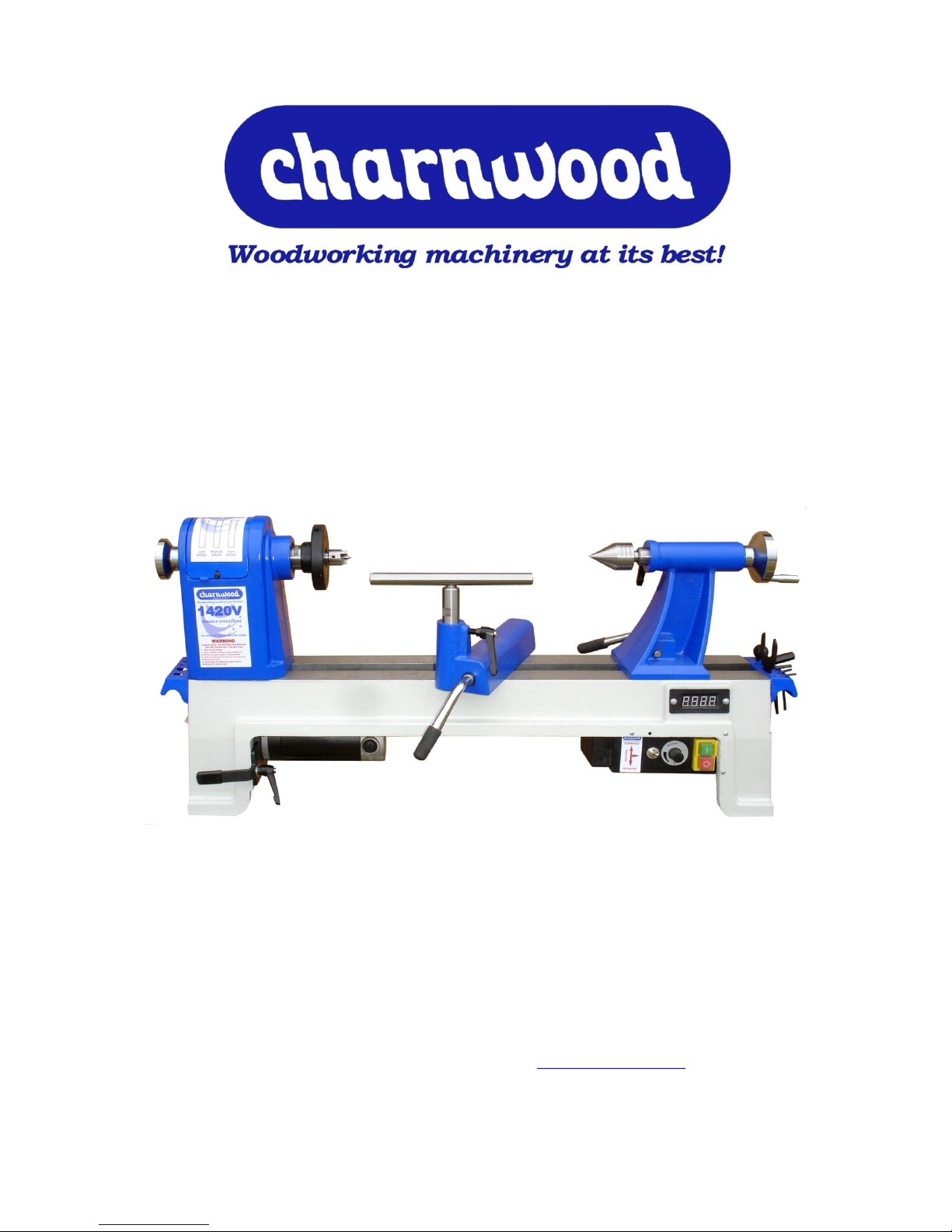
HEAVY DUTY ELECTRONIC VARIABLE
SPEED BENCH LATHE
MODEL: 1420V
Charnwood, Cedar Court, Walker Road,
Hilltop Industrial Estate, Bardon Hill, Leicestershire, LE67 1TU
Tel. 01530 516 926 Fax. 01530 516 929
email: sales@charnwood.net website: www.charnwood.net
Page 2

GENERAL SAFETY RULES
WARNING: Do not attempt to operate the machine until you have read thoroughly and
understood completely all instructions, rules, etc. contained in this manual. Failure to comply
may result in accidents involving fire, electric shock, or serious personal injury. Keep this
owner's manual and review frequently for continuous safe operation.
1. Know your machine. For your own safety, read the owner's manual carefully. Learn its
application and limitations, as well as specific potential hazards pertinent to this machine.
2. Make sure all tools are properly earthed.
3. Keep guards in place and in working order. If a guard must be removed for maintenance
or cleaning, make sure it is properly replaced before using the machine again.
4. Remove adjusting keys and spanners. Form a habit of checking to see that the keys and
adjusting spanners are removed from the machine before switched it on.
5. Keep your work area clean. Cluttered areas and workbenches increase the chance of an
accident.
6. Do not use in dangerous environments. Do not use power tools in damp or wet locations,
or expose them to rain. Keep work areas well illuminated.
7. Keep children away. All visitors should be kept a safe distance from the work area.
8. Make workshop childproof. Use padlocks, master switches and remove starter keys.
9. Do not force the machine. It will do the job better and be safer at the rate for which it is
designed.
10. Use the right tools. Do not force the machine or attachments to do a job for which they
are not designed. Contact the manufacturer or distributor if there is any question about the
machine's suitability for a particular job.
11. Wear proper apparel. Avoid loose clothing, gloves, ties, rings, bracelets, and jewellery
which could get caught in moving parts. Non-slip footwear is recommended. Wear protective
hair covering to contain long hair.
12. Always use safety glasses. Normal spectacles only have impact resistant lenses. They
are not safety glasses.
13. Do not over-reach. Keep proper footing and balance at all times.
14. Maintain machine in good condition. Keep machine clean for best and safest
performance. Follow instructions for lubrication and changing accessories.
15. Disconnect the machine from power source before servicing and when changing the
drive belt.
16. To avoid accidental starting, make sure the switch is in the OFF position before plugging
in the mains cable.
Page 3

17. Never leave the machine running unattended. Turn the power off. Do not leave the
machine until it comes to a complete stop.
18. Do not use any power tools while under the effects of drugs, alcohol or medication.
19. Always wear a face or dust mask if operation creates a lot of dust and/or chips. Always
operate the tool in a well ventilated area and provide for proper dust removal. Use a suitable
dust extractor.
ADDITIONAL RULES FOR LATHES
Never attempt to adjust any part of the workpiece whilst the lathe is still in motion. Wait until
the workpiece has come to a complete stop.
1. Ensure that chuck keys, tommy bars and similar items are removed before the lathe is
started.
2. Always stand to one side when you start the lathe so that if anything does fly off e.g. a
loose piece of bark, you will be out of the line-of-fire.
3. When mounting a new piece of timber, rotate the wood through 360
o
by hand to ensure
that it will not hit the tool rest or the bed of the lathe and then start the lathe at its slowest
speed. When you are certain that that the work is secure and not too out of balance set the
lathe to the normal turning speed.
4. Always check the rotation speed before switching the lathe on to avoid the risk of starting
it whilst it is set to run at too high a speed.
5. The speed of the lathe must be adjusted to suit the size, balance, length and condition of
the timber being turned. The greater the diameter of the work, the slower the rotation speed
needs to be. If the piece you are turning is out of balance, then you must start turning at a
low speed, until it is balanced.
6. The tool must rest firmly on the tool rest before it is brought into contact with the rotating
wood and must never be lifted off the tool rest as long as it is in contact with the timber.
7. Before sanding, polishing or doing anything else that brings your fingers close to the work,
remove the tool rest. Getting your fingers trapped between the tool rest and the work will at
least be very painful and may cause serious injury.
8. Never wrap the sandpaper of polishing cloth round the work. If it tightens up it will pull
your fingers into contact with the timber and may lead to serious injury.
Important
Risk of Injury! Wear Eye Wear Ear
Never reach into Protection Protection
Moving parts
Page 4
Introduction
In order to get the most out of your lathe, please read through this manual and safety
instructions before use.
Please keep the manual in case you need it in the future.
Technical Data
N.B. The distance between centres will vary and be dependent on the type of centres or
accessories used. Maximum distance is 500mm (20”).
Max. spindle Length (with centres fitted)
430mm (17")
Distance over bed
350mm (14")
Motor DC (Carbon Brush)
750w (1hp) 240Vdc
Speed Range (Forward & Reverse) Low
Medium
High
250 - 1400rpm
400 - 2650rpm
600 - 4300rpm
Spindle thread size
M33 x 3.5mm
Spindle tapers
2MT
Indexing Positions
24 ( every 15 degrees)
Dimensions (WxDxH)
950mm x 370mm x 500mm
Weight
57kg
Rating
Hobby
Warranty
1 Year
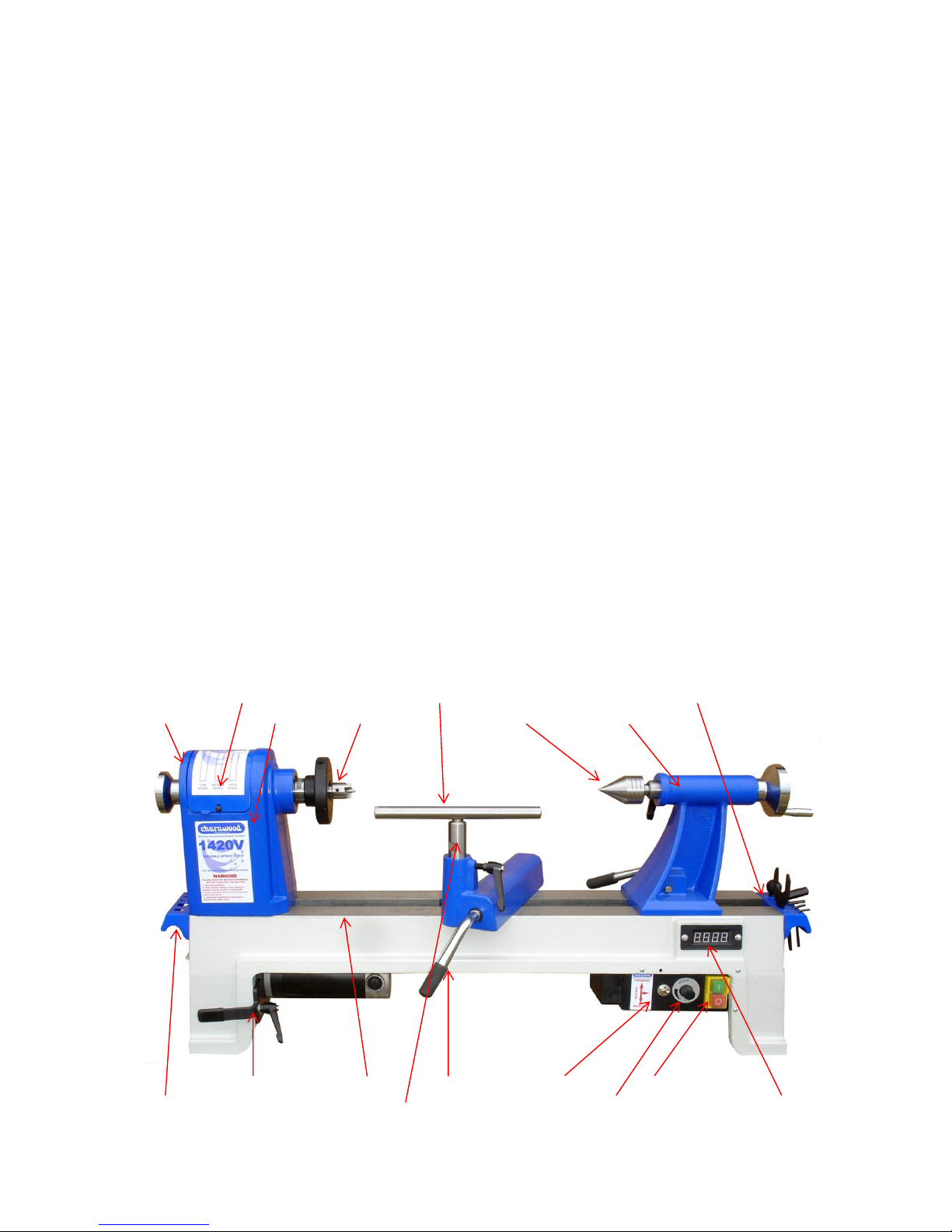
Main Components
Belt Cover Tool Rest Crossbar Tool Rack/Lifting Handle
Indexing Pin Headstock Drive Centre Tail Centre Tailstock
Drive Belt Tensioner Lathe Bed Cam Lock Reversing Switch Start/Stop Buttons
Tool Rack/Lifting Handle Tool Rest Stem Variable Speed Control Digital Speed Display
Page 5
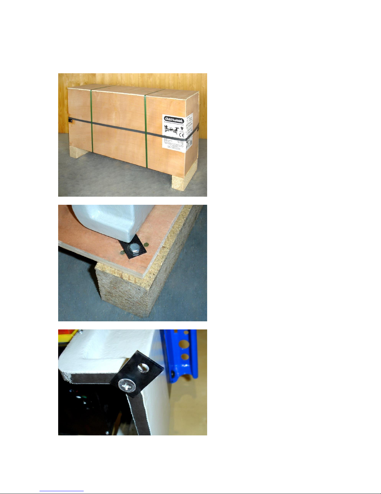
Unpacking
All parts are contained in one pallet
crate.
Cut the retaining straps and
unscrew the corner brackets
before prising apart the top and
sides of the crate. Care must be
taken as they are secured with
sharp pins.
Using a 13mm spanner, remove
the two coach screws securing the
lathe to the pallet
Gently lay the lathe on its side and,
using a cross head screwdriver,
remove the two metal brackets and
discard.
Page 6
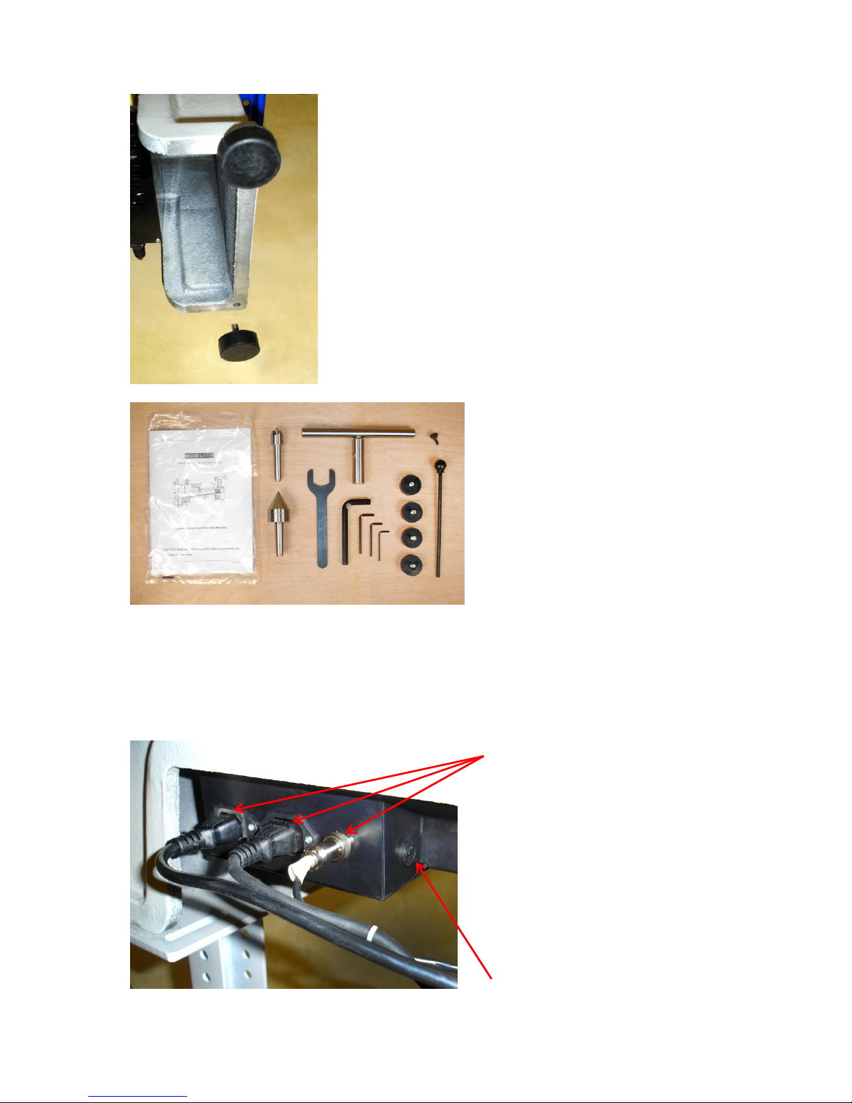
If you decide to bench mount your
lathe, without permanently fixing it,
you should now attach the four
rubber feet to the same holes in
the lathe bed.
The lathe is sufficiently heavy and
stable to be used without fixing to a
base provided the workpiece is not
too large and the blank well
balanced. For larger diameter
blanks (6” plus) and unbalanced
pieces, it is recommended that the
lathe is fixed to a suitable stand or
bench.
In that case, remove the rubber
feet and mount directly using the
holes in the cast bed.
Unpack the parts carefully and
check that everything is present as
shown.
If anything is missing contact your
retailer immediately.
Assembling the Lathe
Decide where you wish to mount your lathe. Ideally, the height of the spindle should be
approximately level with your elbow when standing/sitting in a working position.
Check that the Power & Control
cables are connected to the
sockets in the rear of the Speed
Control Box.
PLEASE NOTE:
THE POWER CORD MUST
NEVER BE CONNECTED
DIRECTLY TO THE MOTOR
CABLE AS THE MOTOR IS A
DIRECT CURRENT TYPE AND
WOULD BE PERMANENTLY
DAMAGED.
Fuse Holder
Page 7

Adjusting the Spindle Speed
The lathe has electronic speed
control. There are three ranges of
speeds which are obtained by
changing the position of the drive
belt.
To adjust the drive belt position:
1) Remove the bottom pulley
access door by first loosening the
four pozi-head securing screws.
Then raise and lift off the door.
2) Open the upper belt cover by
first loosening the retaining screw
with a 3mm hex key. An
alternative knurled head screw is
supplied with the lathe, but this
should not be fitted if the lathe is
being used within the European
Union.
Page 8

3) Loosen the belt tension lever
locking handle.
4) Lift the belt tension lever and
tighten the locking handle..
5) Move the slack belt to the
alternate set of pulleys. Always
remove the belt from the larger
pulley first. Release the locking
lever, apply light pressure to
tension the belt and then retighten the locking handle.
6) Close the belt cover and re-fit
the pulley door.
Forward/Reverse Switch On/Off Switch
Variable Speed Control
After switching on the lathe,
adjust the speed using the
variable speed control knob.
The approximate speed ranges
are:
Left Hand Pulleys:
250rpm to 1400rpm
Centre Pulleys:
400rpm to 2650rpm
Right Hand Pulleys:
600rpm to 4300rpm
The actual spindle speed will be
displayed on the LED Indicator.
Page 9

Recommended Turning Speeds
Workpiece
Diameter mm
Roughing Cuts
RPM
General Cutting
RPM
Finishing Cuts
RPM
Under 50
1500
3200
3200
50-100
750
1600
2500
100-150
500
1000
1700
150-200
500
800
1250
200-250
500
650
1000
250-300
500
530
850
Forward/Reverse Control
The Forward/Reverse switch should never be used when the lathe spindle is still rotating.
Always stop the lathe by using the ON/OFF switch and wait for the workpiece to come to a
standstill.
IMPORTANT The lathe should be reversed
only if the chuck or faceplate is locked onto
the spindle thread (e.g. with a grub screw) or
when turning between centres with the
morse taper drive centre.
Some chucks are not equipped with any form
of locking and should never be used in
reverse.
The faceplate supplied with the lathe has two
thread-locking grub screws.
Using the Lathe
Fine adjustment of the tail centre is
made by unlocking the winding handle
locking lever (by half a turn only).
Turn the winding handle to enable the
tail centre to be advanced or retracted.
It has a travel of 70mm.
To slide the tailstock along the bed, pull
up the silver tailstock locking lever.
When it is positioned where required,
clamp it firmly in place by pressing the
lever down firmly.
Page 10

The height of the tool rest can also
be adjusted, using the black locking
lever.
This type of lever can be rotated to a
more convenient position, without
moving the thread, by pulling the
lever away from the thread to
disengage the ratchet teeth and then
rotating it.
The tool rest banjo can be moved
along the bed of the lathe.
To release the tool rest banjo pull up
the silver tool rest locking lever.
The tool rest can now freely slide
along the bed, when it is positioned
where required, clamp it firmly in
place by pressing the lever down
firmly.
Using the Indexing System
The lathe is fitted with an indexing system which allows the spindle to be locked in 24
positions (ie. at 15 degree intervals). The indexing facility is useful for fluted columns, clock
faces and accurate hole placements.
Page 11

To set a position:
Lift the top belt pulley cover to expose the indexing ring. Mark a convenient position on the
headstock casting and turn the faceplate to line up the required indexing position with it.
Then lift and rotate the indexing pin, at the rear of the headstock, which will engage with the
appropriate slot. The spindle is now locked in place.
To lock or unlock the spindle:
Lift and rotate the locking knob. Ensure that the horizontal pin is engaged in the shallow
groove and the spindle is free to rotate before starting the lathe. Failure to do so could result
in damage to the indexing mechanism.
Index Pin Disengaged Index Pin Engaged
IMPORTANT The indexing pin should never be used as a spindle lock as this could result in
damage to pin and indexing wheel. Always use the spanner supplied to lock the spindle.
Page 12

Routine Maintenance
Replacing the Drive Belt
Eventually, the drive belt will become
worn and require replacement.
To replace the belt, remove the motor
pulley cover and top pulley access
cover.
Remove the chrome hand wheel from
the spindle by unscrewing it from the
spindle. Hold the spindle with the
spanner and unscrew the handwheel
anticlockwise using the knock-out bar
as a lever. Remove the cover plate
surrounding the spindle to allow access
for the belt
Release the tension as when changing
the speed range and remove the old
belt by feeding it over the end of the
spindle and through the aperture in the
headstock casting.
Page 13

Replace by feeding the new belt
through the opening in the lathe bed
and over the bottom pulley, then over
the corresponding upper pulley. Apply
tension and tighten the locking handle.
Ensure that the V- grooves are on the
inside of the belt and engaged with the
grooves on the pulleys.
Replacing the Motor Brushes
The carbon brushes should be regularly
inspected and will need changing after
approximately 500 hours use, or when the
block has worn down to a length of 7mm.
Unscrew the two black plastic screws found
on either side of the motor.
Withdraw the worn brush and spring, then
replace it with a new one.
Always replace both brushes at the same
time.
Page 14

Optional Accessories
Our full range of accessories can be viewed on our website: www.charnwood.net
Viper3 Geared Scroll Chuck,
70mm Diameter.
A compact scroll chuck, with the
jaws adjusted by a geared
mechanism for simple one handed
operation. Self-centring, high
precision design.
DC16MT2 Drill Chuck
16mm Chuck Capacity with No.2
Morse taper (MT2) fitting.
Supplied with chuck key.
ULEG A heavy duty floor stand
ideal for the 1420v lathe.
The two platforms have a series of
slotted holes for securely mounting
the lathe to the stand. The height of
the stand is also adjustable so a
comfortable working height can be
set.
Supplied with 4 adjustable rubber
feet.
Page 15

Fault Possible Cause Remedy
Machine will not start Power supply not connected Check plug connections in rear of control unit
Fuse in plug blown Replace fuse
Fuse in Control Box blown Replace Fuse
Break in power supply cable Visually check cable - replace if necessary
Loose terminal on switch Remove switch and check connections
Switch failed Replace switch
Machine will not start, Speed Display Lit Indexing Pin Engaged Disengage Indexing Pin
Fuse in Control Box blown Replace fuse
Speed controller failed Replace speed controller
Carbon brushes worn Replace carbon brushes
Machine starts only when green button held Switch has failed Replace Switch
Machine starts to turn but slow speed only Failed variable speed circuit Check connection to speed dial
Spindle stalls but motor still running Loose drive belt Increase belt tension
Motor is running but spindle not turning Broken drive belt Replace drive belt
Motor is overheating Too much load on motor Reduce load - make shallower cuts
Airflow around motor restricted Keep motor clear of shavings
Spindle rotation slows during cut Excessive depth of cut Make shallower cuts
Chisels are dull Sharpen chisels
Worn carbon brushes Replace brushes
Loose drive belt Increase belt tension
CHARNWOOD 1420V LATHE TROUBLESHOOTING GUIDE
Page 16

Charnwood 1420V Wiring Diagram
Page 17

Declaration of Conformity for CE Marking
Charnwood Declare that Woodworking Lathe, Model 1420V
Conforms with the following Directives: Machinery Directive 2006/42/EC
And further conforms to the machinery example for which the EC type examination
Certificate No. AM 50387407 which has been issued by TUV Rheinland LGA Products
GmbH, Tillystrasse 2, 90431, Nurnberg, Germany.
I hereby declare that equipment named above has been tested and found to comply with the
relevant sections of the above referenced specifications. The machinery complies with all
essential requirements of the directive.
Signed: Dated: 11/09/2017 Location: Leicestershire
Richard Cook
Director
Please dispose of packaging for the product in a responsible manner.
It is suitable for recycling. Help to protect the environment, take the
packaging to the local amenity tip and place into the appropriate
recycling bin.
Only for EU countries
Do not dispose of electric tools together with household waste material!
In observance of European Directive 2002/96/EC on waste electrical
and electronic equipment (EEE) and its implementation in accordance
with national law, electric tools that have reached the end of their life
must be collected separately and returned to an environmentally
compatible recycling facility.
Your local refuse amenity will have a separate collection area for EEE
goods
Page 18

Charnwood 1420V Parts List
Part No
Description
Part No
Description
01
Rubber Foot
02
D.C. Motor
03
Belt Tension Lock Lever
04
Flat Washer
05
Motor Plate
06
Cap Head Screw
08
Grub Screw
09
Cap Head Screw
10
Bed 11
Belt Door
12
Cross Head Screw
13
Screw
14
Cap Head Screw
15
Flat Washer
16
Handle
17
Cap Head Screw
18
Spring Washer
19
Headstock
20
Digital Readout Sensor
21
Location Pin Assembly
22
Spindle Pulley
23
Drive Belt 310J
24
Headstock Wheel
25
Locking Nut
26
Knockout Rod Assembly
27
Cover For Motor Pulley
28
Cap Head Screw
29
Grub Screw
30
Bearing
31
Circlip
32
Bearing 6005
33
Spindle
34
Cap Head Screw
35
Face Plate
36
Drive Centre
37
Revolving Tail Centre
38
Sleeve
39
Tailstock
40
Quill Lock Lever
41
Pin
42
Leadscrew
43
Tailstock Wheel
44
Handwheel Axle
45
Washer
46
Handwheel Handle
47
Grub Screw
48
Tailstock Lock Lever
49
Grub Screw
50
Tailstock Clamp Bolt
51
Tailstock Clamp
52
Nut 53
Circlip
54
Cross Head Screw
55
Cable Hook
56A
Tool Rest Stem 25mm Dia.
56B
Tool Rest Crossbar
57
Circlip 58
Banjo
59
Handle
60
Tool Rest Clamp Bolt
61
Tube 62
Banjo Lock Lever
71
Cross Head Screw
75
RPM Digital Readout
77
Wrench
78
Allen Key 3mm
79
Allen Key 4mm
80
Allen Key 5mm
81
Allen Key 12mm
82
Knob
83
Motor Pulley
84
Motor
85
Power Lead
86
Circuit Board
87
Connector for Motor Plug
88
Connector for Power Lead
89
Electrical Box
90
Rubber Grommet
91
Speed Controller
92
Variable Speed Knob
93
Box Cover
94
Switch - KJD20
95
Cross Head Screw
96
Cross Head Screw
97
FWD/REV Toggle Switch
BRUSH
Carbon Brushes x2
VS
Control Unit Complete
Parts # 86-94 + 96
Page 19

Charnwood 1420V Parts Drawing
Page 20

Updated March 2018
Charnwood, Cedar Court, Walker Road,
Hilltop Industrial Estate, Bardon Hill, Leicestershire, LE67 1TU
Tel. 01530 516 926 Fax. 01530 516 929
email: sales@charnwood.net website: www.charnwood.net
 Loading...