

Page 1

Plastics
TECHNICAL AND INSTALLATION MANUAL
(Updated November 2008)
TM-ABS-PVC-CPVC
TECHNICAL MANUAL
© 2001-2008 Charlotte Pipe and Foundry Co.
Page 2

Monroe, North Carolina
INTRODUCTION
Charlotte Pipe® has been relentless in our commitment
to quality and service for more than a century. Through
the years we have broadened and enhanced our product
lines to better serve our customers. As the leading full-line
manufacturer of PVC, CPVC, and ABS piping systems for
drainage and pressure applications, we welcome the
opportunity to be the one-stop source for all your
thermoplastic piping systems. Charlotte
company that manufactures pipe and fittings to exacting
TrueFit tolerances. Our systems are designed to fit together
precisely for easier installation, fewer callbacks and a
lifetime of trouble-free service - the major benefits of a
Charlotte Pipe TrueFit® system.
®
Plastics Technical Manual
is the only
Muncy, Pennsylvania
Cameron, Texas
Huntsville, Alabama Cedar City, Utah
Manufacturing
Facilities
• Monroe, North Carolina
• Muncy, Pennsylvania
• Cameron, Texas
• Wildwood, Florida
• Huntsville, Alabama
• Cedar City, Utah
Wildwood, Florida
Charlotte Pipe, Charlotte, Charlotte Pipe TrueFit, and "You can't beat the system" are registered trademarks of Charlotte Pipe and Foundry Company.
2
Page 3
TABLE OF CONTENTS
GENERAL INFORMATION Page
Introduction ..........................................................................................................2
Major Advantages of ABS, PVC and CPVC Pipe .................................................. 4
Handling and Storage of ABS, PVC and CPVC Pipe ............................................. 5
Physical Properties of ABS and PVC Materials..................................................... 6
ABS and PVC Standards ....................................................................................... 6
Physical Properties of CPVC Materials .................................................................7
CPVC Standards ....................................................................................................7
Recommended Product Specifications.............................................................8-18
ABS Cellular Core (Foam Core) Pipe and ABS DWV Fitting System ................... 8
PVC Schedule 40 Solid Wall Pipe and PVC DWV Fitting System ....................... 9
PVC Cellular Core (Foam Core) Pipe and PVC DWV Fitting System .................10
PVC Schedule 40 Pressure Pipe and Fitting System ......................................... 11
PVC SDR Pressure Pipe and Fitting System ..................................................... 12
PVC Schedule 80 Pressure Pipe and Fitting System ......................................... 13
CPVC Schedule 80 Corzan
PVC SDR 35 Gravity Sewer Pipe ..................................................................... 15
PVC Cellular Core (Foam Core) Sewer Pipe PS 50/ Sewer and
Drain Series .................................................................................................... 16
Product Certification .......................................................................................... 17
Pipe Reference Guide .......................................................................................... 18
Pipe Data (Dimensions, Weight and Pressure Ratings) ..................................19-29
Socket Dimensions for Belled-End Pipe .............................................................. 26
DESIGN AND ENGINEERING DATA
Pressure/Temperature Relationship ..................................................................... 30
Low Temperature Recommendations................................................................. 30
Fluid Flow Properties .....................................................................................31-35
Gravity Flow and Fluid Flow Rate .................................................................... 31
Pressure Flow Rate ..........................................................................................32
Friction Loss Through Fittings .........................................................................32
Water Hammer / Entrapped Air..................................................................33-35
Weathering UV Exposure ................................................................................35
Friction Loss and Flow Velocity Table .........................................................36-40
Support Spacing for ABS, PVC and CPVC Pipe ............................................ 41-42
Typical Pipe Hangers, Clamps, and Supports ...................................................... 42
Expansion and Contraction of ABS, PVC and CPVC .......................................... 43
Underground Installation ....................................................................................44
Installation Procedures ..................................................................................45-46
Joint Curing ........................................................................................................47
Testing Pressure System .....................................................................................47
Flanges and Unions PVC and CPVC Pipe ............................................................ 48
Threaded Joints and Threading of PVC and CPVC Pipe ................................ 49-50
Antifreeze Solutions ............................................................................................ 51
Joining Roll-Grooved Pipe ...................................................................................51
Testing DWV and Inspection ...............................................................................52
Hydronic Heating Applications ...........................................................................53
Material Selection ...............................................................................................54
Engineered Applications ..................................................................................... 54
Unstable Soil .......................................................................................................54
Venting Combustion Gases.................................................................................. 54
CHEMICAL RESISTANCE CHART OF ABS, PVC AND CPVC ............................. 55-70
QUICK REFERENCE FACT SHEETS ...................................................................71-85
CONVERSION CHARTS .......................................................................................86-87
LIMITED WARRANTY............................................................................................... 88
HELPFUL REFERENCE STANDARDS .................................................................89-92
®
Pressure Pipe and Fitting System .......................... 14
3
Page 4

MAJOR ADVANTAGES OF
ABS, PVC AND CPVC PIPE
Product Advantage
• While ABS, PVC and CPVC are very different
materials, they share numerous advantages common
to plastic piping systems. Advantages include ease of
installation, corrosion resistance, low friction loss,
initial cost, and longevity.
Easy Installation
• ABS, PVC and CPVC systems are light in weight
(approximately one-half the weight of aluminum and
one-sixth the weight of steel) reducing transportation,
handling, and installation cost. They have smooth,
seamless interior walls. No special tools are required
for cutting. These materials can be installed using
the solvent cementing joining technique.
Strength
• ABS, PVC and CPVC products are highly resilient,
tough and durable with high tensile and high impact
strength.
Freedom from Toxicity, Ordors, Tastes
• PVC and CPVC piping are non-toxic, odorless, and
tasteless. They have been listed by the National
Sanitation Foundation for use with potable water.
Corrosion Free External and Internal
• With many other pipe materials, slight corrosion may
occur. The corroded particles can contaminate the
piped fluid, complicating further processing, or
causing bad taste, odors, or discoloration. This is
particularly undesirable when the piped fluid is for
domestic consumption. With PVC and CPVC, there
are no corrosive by-products, therefore, no
contamination of the piped fluid.
Immunity to Galvanic or Electrolytic Attack
• ABS, PVC and CPVC are inherently immune to
galvanic or electrolytic action. They can be used
underground, underwater, in the presence of metals,
and can be connected to metals.
Fire Resistance
• PVC and CPVC piping systems are self extinguishing
and will not support combustion. The ASTM E 84
test protocol is used to determine the flame and smoke
rating for various materials.
• PVC will not pass the ASTM E-84 25/50 flame spread
/ smoke developed test and is not acceptable for use
in plenum areas.
• Consult Charlotte Pipe for additional information on
CPVC in plenum applications.
• For plenum applications, follow prevailing code
requirements.
Low Friction Loss
• The smooth interior surfaces of ABS, PVC and CPVC
assure low friction loss and high flow rate.
Additionally, since ABS, PVC and CPVC pipe will
not rust, pit, scale, or corrode, the high flow rate will
be maintained for the life of the piping system.
4
Plastics Technical Manual
Low Thermal Conductivity
• PVC and CPVC pipe have a much lower thermal
conductivity factor than metal pipe. Therefore, fluids
being piped maintain a more constant temperature.
In most cases, pipe insulation is not required.
Cost Effective
• ABS, PVC and CPVC products are extremely light
weight, convenient to handle, relatively flexible, and
easy to install. These features lead to lower installed
cost than other piping systems.
Maintenance Free
• Once an ABS, PVC or CPVC system is properly
selected, designed, and installed, it is virtually
maintenance free. It will not rust, pit, scale, corrode,
or promote build-up on the interior. Therefore, years
of trouble-free service can be expected when using
Charlotte Pipe and Foundry ABS, PVC and CPVC
systems.
DO NOT USE CHARLOTTE PIPE PRODUCTS
FOR COMPRESSED AIR OR GASES
Charlotte Pipe and Foundry Company products are not
intended to be used for distribution or storage of
compressed air or gases. Use of Charlotte Pipe products
in inappropriate applications could result in product
failure, serious injury or death.
Air or Gas Testing - Not Recommended
Air or compressed gas test are sometimes performed
instead of hydrostatic (water) test. DANGER: Charlotte
Pipe and Foundry Company does not recommend air or
gas testing, consistent with PPFA User Bulletin 4-80
and / or ASTM D 1785.
under air or gas pressure can explode, causing
serious injury or death.
responsible or liable for injury or death to persons or
damage to property or for claims for labor and / or
material arising from any alleged failure of our products
during testing with air or compressed gasses.
Pipe and fitting materials
Charlotte Pipe will not be
Page 5
HANDLING AND STORAGE
OF ABS, PVC AND CPVC PIPE
Receiving Pipe:
As pipe is received, it must always be thoroughly
inspected, prior to unloading. The person receiving the
pipe must look for any transportation damage caused by
over-tightened tie-down straps, improper treatment, or
a shift in the load.
Pipe received in a closed trailer must be inspected as the
trailer is opened. Take extra time to ensure that the pipe
has not been damaged by other materials having been
stacked on top of it, load shift, or rough handling.
Visually examine the pipe ends for any cracks, splits,
gouges, or other forms of damage. Additionally, the pipe
should be inspected for severe deformation which could
later cause joining problems. The entire inside diameter
of larger diameter pipe (4
"
and above) must be checked
for any internal splits or cracks which could have been
caused by loading or transit. The use of a flashlight may
be necessary to perform this inspection.
Any damages must be observed by all parties involved,
including the driver, and should be clearly noted on the
bill of lading and/or delivery ticket. A copy of this
document should be retained by the receiver. In addition,
the manufacturer and carrier should be notified, within
24 hours, of any damages, shortages, or mis-shipped
products.
Handling Pipe:
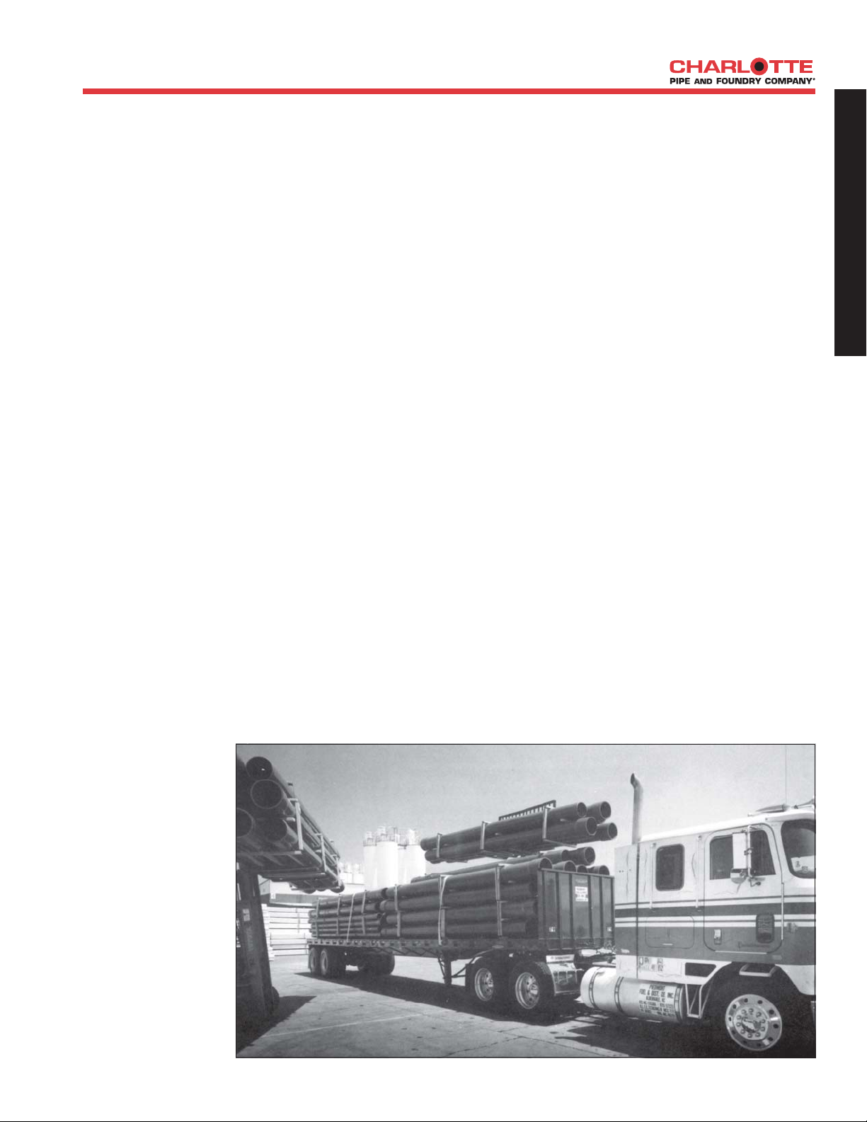
The pipe should be handled with reasonable care. Because
thermoplastic pipe is much lighter in weight than metal
pipe, there is sometimes a tendency to throw it around.
This should be avoided.
The pipe should never
be dragged or pushed
from a truck bed.
Removing and
handling pallets of
pipe should be done
with a forklift. Loose
pipe lengths require
special handling to
avoid damage.
Precautions to follow
when unloading and
handling loose pieces
include not banging
lengths together or
dropping lengths,
even from low
heights, on hard or
uneven surfaces.
In all cases, severe contact with any sharp objects (rocks,
angle irons, forks on forklifts, etc.) should be avoided.
Also, the pipe should never be lifted or moved by inserting
the forks of a forklift into the pipe ends.
Handling PVC and particularly CPVC pipe diameters
greater than 4-inch requires extra care as the added pipe
weight can cause cracking from relatively minor impacts.
Also, plastic pipe becomes more brittle as the
temperature decreases. The impact strength and
flexibility of PVC and especially CPVC pipe are reduced.
Therefore, take extra care when handling skids or loose
lengths when the temperature drops below 50° F.
Storing Pipe:
If possible, pipe should be stored inside. When this is
not possible, the pipe should be stored on level ground
which is dry and free from sharp objects. If different
schedules of pipe are stacked together, the pipe with the
thickest walls should be on the bottom.
If the pipe is in pallets, the pallets should be stacked
with the pallet boards touching, rather than pallet boards
being placed on the pipe. This will prevent damage to or
bowing of the pipe.
If the pipe is stored in racks, it should be continuously
supported along its length. If this is not possible, the
spacing of the supports should not exceed three feet (3').
The pipe should be protected from the sun and be in an
area with proper ventilation. This will lessen the effects
of ultraviolet rays and help prevent heat build-up.
G
E
N
E
R
A
L
I
N
F
O
R
M
A
T
I
O
N
5
Page 6
PHYSICAL PROPERTIES OF
ABS AND PVC MATERIALS
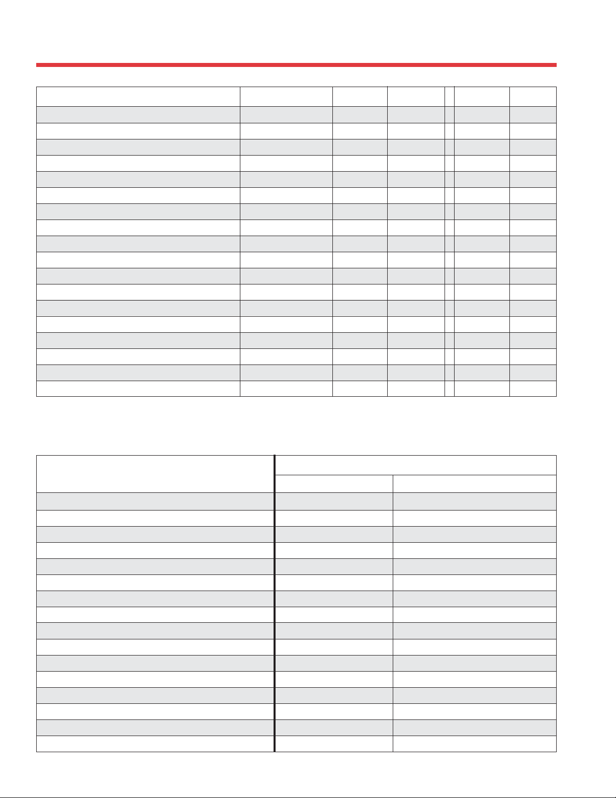
PROPERTY UNITS ABS ASTM NO. PVC ASTM NO.
Specific Gravity g/cc 1.05 D 792 1.40 D 792
Tensile Strength (73°F) Minimum Psi 4,500 D 638 7,000 D 638
Modulus of Elasticity in Tension (73°F) Minimum Psi 240,000 D 638 400,000 D 638
Flexural Strength (73°F) Psi 10,585 D 790 14,000 D 790
Izod Impact (notched at 73°F) Minimum ft lb/ in. 6.00 D 256 0.65 D 256
Hardness (Durometer D) 70 D 2240 80 ± 3 D 2240
Hardness (Rockwell R) 100 D 785 110 - 120 D 785
Compressive Strength (73°F) Psi 7,000 D 695 9,600 D 695
Hydrostatic Design Stress Psi N/A 2,000 D 1598
Coefficient of Linear Expansion in./ in./ °F 5.5 x 10
Heat Distortion Temperature at 264 psi Minimum degrees F 180 D 648 160 D 648
Coefficient of Thermal Conductivity BTU/ hr/sq ft/ °F/ in. 1.1 C 177 1.2 C 177
Specific Heat BTU/ °F/lb 0.35 D 2766 0.25 D 2766
Water Absorption (24 hrs at 73°F) % weight gain 0.40 D 570 .05 D 570
Cell Classification - Pipe 42222 D 3965 12454 D 1784
Cell Classification - Fittings 32222 D 3965 12454 D 1784
Burning Rate Self Ext. D 635
Burning Class V-0 UL 94*
Above data is based upon information provided by the raw material manufacturers. It should be used only as a
recommendation and not as a guarantee of performance. * Underwriters Laboratories standard
-5
D 696 3.0 x 10⁻⁵D 696
Plastics Technical Manual
ABS and PVC Standards
TYPE PIPE / FITTING
MATERIAL DIMENSIONS
ABS DWV
Schedule 40 DWV Foam Core Pipe ASTM D 3965 ASTM F 628
Schedule 40 DWV Fittings ASTM D 3965 ASTM D 2661
PVC DWV
Schedule 40 DWV Pipe ASTM D 1784
Schedule 40 DWV Foam Core Pipe ASTM D 4396 ASTM F 891
Schedule 40 DWV Fittings ASTM D 1784 ASTM D 2665
PVC Pressure
Schedule 40 Plain End Pipe ASTM D 1784 ASTM D 1785
Schedule 40 Bell End Pipe ASTM D 1784 ASTM D 1785
Schedule 40 Bell End Well Casing ASTM D 1784 ASTM D 1785 & ASTM F 480
SDR 21 (PR 200) Bell End Pipe ASTM D 1784 ASTM D 2241
SDR 26 (PR 160) Bell End Pipe ASTM D 1784 ASTM D 2241
Schedule 40 Fittings ASTM D 1784 ASTM D 2466
Schedule 80 Plain End Pipe ASTM D 1784 ASTM D 1785
Schedule 80 Fittings ASTM D 1784 ASTM D 2464 & ASTM D 2467
STANDARD SPECIFICATIONS
ASTM D 2665 & ASTM D 1785
6
Page 7
PHYSICAL PROPERTIES OF
CORZAN CPVC MATERIALS
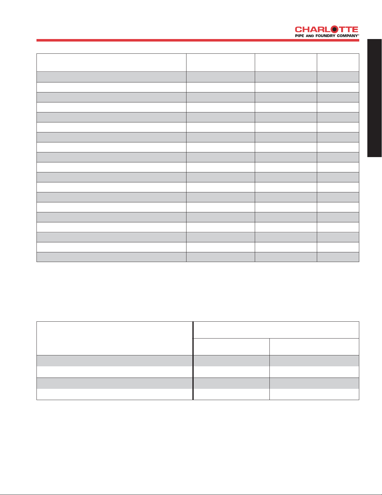
PROPERTY CPVC 4120 UNITS ASTM No.
Specific Gravity 1.55 g/cc D 792
Tensile Strength (73°F) Minimum 7,000 psi D 638
Modulus of Elasticity in Tension (73°F) 360,000 psi D 638
Flexural Strength (73°F) 15,100 psi D 790
Izod Impact Cell Class 23447 (notched at 73°F) Minimum 1.5 ft lb/ in. of notch D 256
Izod Impact Cell Class 24448 (notched at 73°F) Minimum 5.0 ft lb/ in. of notch D 256
Hardness (Durometer D) — D 2240
Hardness (Rockwell R) 119 D 785
Compressive Strength (73°F) 10,100 psi D 695
Hydrostatic Design Stress 2,000 psi
Coefficient of Linear Expansion 3.4 x 10
Heat Distortion Temperature at 264 psi Minimum 212 (Cell Class 23447) degrees F D 648
Heat Distortion Temperature at 264 psi Minimum 230 (Cell Class 24448) degrees F D 648
Coefficient of Thermal Conductivity .95 BTU/ hr/sq ft/ °F/ in. C 177
Specific Heat — cal/ °C/ gm D 2766
Water Absorption (24 hrs at 73°F) .03 % weight gain D 570
Cell Classification 23447 - 24448 D 1784
Burning Rate Self Extinguishing D 635
Burning Class V-0 UL 94*
-5
in./ in./ °F D 696
G
E
N
E
R
A
L
I
N
F
O
R
M
A
T
I
O
N
Above data is based upon information provided by the raw material manufacturers. It should be used only as a
recommendation and not as a guarantee of performance. * Underwriters Laboratories standard
CPVC Standards
STANDARD SPECIFICATIONS
TYPE PIPE / FITTINGS
MATERIAL DIMENSIONS
CPVC Pressure
CPVC Schedule 80 Plain End Pipe ASTM D 1784 ASTM F 441
CPVC Schedule 80 Fittings ASTM D 1784 ASTM F 437 and ASTM F 439
7
Page 8

RECOMMENDED PRODUCT
SPECIFICATION
Plastics Technical Manual
Suggested Specification
System: ABS Cellular Core (Foam Core) Pipe and ABS DWV Fitting System
Scope: This specification covers ABS cellular core (foam core) pipe and ABS DWV fittings used in sanitary
drain, waste, and vent (DWV), sewer, and storm drainage applications. This system is intended for use in
non-pressure applications where the operating temperature will not exceed 160°F.
Specification: Pipe shall be manufactured from virgin rigid ABS (acrylonitrile-butadiene-styrene) compounds with a
Cell Class of 42222 as identified in ASTM D 3965. Fittings shall be manufactured from virgin rigid ABS
compounds with a Cell Class of 32222 as identified in ASTM D 3965.
ABS cellular core pipe shall be Iron Pipe Size (IPS) conforming to ASTM F 628. ABS DWV fittings shall
conform to ASTM D 2661. Pipe and fittings shall be manufactured as a system and be the product of one
manufacturer. All pipe and fittings shall be manufactured in the United States. All systems shall utilize a
separate waste and vent system. Pipe and fittings shall conform to National Sanitation Foundation Standard
14.
Installation shall comply with the latest installation instructions published by Charlotte Pipe and Foundry
and shall conform to all local plumbing, fire, and building code requirements. Buried pipe shall be installed
in accordance with ASTM D 2321 and ASTM F 1668. Solvent cement joints shall be made with a solvent
cement conforming to ASTM D 2235. The system shall be protected from chemical agents, fire stopping
materials, thread sealant, or other aggressive chemical agents not compatible with ABS compounds.
Systems shall be hydrostatically tested after installation. Testing with compressed air or gas is not
recommended. Testing with compressed air or gas may result in injury or death.
Referenced Standards:
ASTM D 3965 Rigid ABS Compounds
ASTM F 628 Co-extruded ABS Pipe with Cellular Core
ASTM D 2661 ABS Drain, Waste, and Vent Fittings
ASTM D 2235 Solvent Cements for ABS Pipe and Fittings
ASTM D 2321 Underground Installation of Thermoplastic Pipe (non-pressure applications)
ASTM F 1668 Procedures for Buried Plastic Pipe
NSF Standard 14 Plastic Piping Components and Related Materials
Note: Latest revision of each standard applies.
Short Specification:
Pipe and fittings shall be manufactured from ABS compound with a cell class of 42222 for pipe and
32222 for fittings as per ASTM D 3965 and conform with National Sanitation Foundation (NSF)
standard 14. Pipe shall be iron pipe size (IPS) conforming to ASTM F 628. Fittings shall conform to
ASTM D 2661.
All pipe and fittings to be produced by a single manufacturer and to be installed in accordance with
manufacturer’s recommendations and local code requirements. Buried pipe shall be installed in accordance
with ASTM D 2321 and ASTM F 1668. Solvent cement shall conform to ASTM D 2235. The system to
be manufactured by Charlotte Pipe and Foundry Company and is intended for non-pressure drainage
applications where the temperature will not exceed 160°F.
8
Page 9

RECOMMENDED PRODUCT
SPECIFICATION
Suggested Specification
System: PVC Schedule 40 Solid Wall Pipe and PVC DWV Fitting System
Scope: This specification covers PVC Schedule 40 solid wall pipe and PVC DWV fittings used in sanitary drain,
waste, and vent (DWV), sewer, and storm drainage applications. This system is intended for use in nonpressure applications where the operating temperature will not exceed 140°F.
Specification: Pipe and fittings shall be manufactured from virgin rigid PVC (polyvinyl chloride) vinyl compounds with
a Cell Class of 12454 as identified in ASTM D 1784.
PVC Schedule 40 pipe shall be Iron Pipe Size (IPS) conforming to ASTM D 1785 and ASTM D 2665.
PVC DWV fittings shall conform to ASTM D 2665. Pipe and fittings shall be manufactured as a system
and be the product of one manufacturer. All pipe and fittings shall be manufactured in the United States.
All systems shall utilize a separate waste and vent system. Pipe and fittings shall conform to National
Sanitation Foundation Standard 14.
Installation shall comply with the latest installation instructions published by Charlotte Pipe and Foundry
and shall conform to all local plumbing, building, and fire code requirements. Buried pipe shall be installed
in accordance with ASTM D 2321 and ASTM F 1668. Solvent cement joints shall be made in a two step
process with primer manufactured for thermoplastic piping systems and solvent cement conforming to
ASTM D 2564. The system shall be protected from chemical agents, fire stopping materials, thread
sealant, plasticized vinyl products, or other aggressive chemical agents not compatible with PVC compounds.
Systems shall be hydrostatically tested after installation. Testing with compressed air or gas is not
recommended. Testing with compressed air or gas may result in injury or death.
G
E
N
E
R
A
L
I
N
F
O
R
M
A
T
I
O
N
Referenced Standards:
ASTM D 1784 Rigid Vinyl Compounds
ASTM D 1785 PVC Plastic Pipe, Schedule 40
ASTM D 2665 PVC Drain, Waste, and Vent Pipe & Fittings
ASTM D 2564 Solvent Cements for PVC Pipe and Fittings
ASTM D 2321 Underground Installation of Thermoplastic Pipe (non-pressure applications)
ASTM F 1668 Procedures for Buried Plastic Pipe
NSF Standard 14 Plastic Piping Components and Related Materials
Note: Latest revision of each standard applies.
Short Specification:
Pipe and fittings shall be manufactured from PVC compound with a cell class of 12454 per ASTM D
1784 and conform with National Sanitation Foundation (NSF) standard 14. Pipe shall be iron pipe size
(IPS) conforming to ASTM D 1785 and ASTM D 2665. Fittings shall conform to ASTM D 2665.
All pipe and fittings to be produced by a single manufacturer and to be installed in accordance with
manufacturer’s recommendations and local code requirements. Buried pipe shall be installed in accordance
with ASTM D 2321 and ASTM F 1668. Solvent cements shall conform to ASTM D 2564, primer shall
conform to ASTM F 656. The system to be manufactured by Charlotte Pipe and Foundry Company and is
intended for non-pressure drainage applications where the temperature will not exceed 140°F.
9
Page 10

RECOMMENDED PRODUCT
SPECIFICATION
Plastics Technical Manual
Suggested Specification
System: PVC Cellular Core (Foam Core) Pipe and PVC DWV Fitting System
Scope: This specification covers PVC cellular core (foam core) pipe and PVC DWV fittings used in sanitary
drain, waste, and vent (DWV), sewer, and storm drainage applications. This system is intended for use in
non-pressure applications where the operating temperature will not exceed 140°F.
Specification: Pipe shall be manufactured from virgin rigid PVC (polyvinyl chloride) vinyl compounds with a Cell Class
of 11432 as identified in ASTM D 4396. Fittings shall be manufactured from virgin rigid PVC (polyvinyl
chloride) vinyl compounds with a Cell Class of 12454 as identified in ASTM D 1784.
PVC cellular core pipe shall be Iron Pipe Size (IPS) conforming to ASTM F 891. PVC DWV fittings shall
conform to ASTM D 2665. Pipe and fittings shall be manufactured as a system and be the product of one
manufacturer. All pipe and fittings shall be manufactured in the United States. All systems shall utilize a
separate waste and vent system. Pipe and fittings shall conform to National Sanitation Foundation Standard
14.
Installation shall comply with the latest installation instructions published by Charlotte Pipe and Foundry
and shall conform to all local plumbing, fire, and building code requirements. Buried pipe shall be installed
in accordance with ASTM D 2321 and ASTM F 1668. Solvent cement joints shall be made in a two step
process with primer manufactured for thermoplastic piping systems and solvent cement conforming to
ASTM D 2564. The system shall be protected from chemical agents, fire stopping materials, thread
sealant, plasticized vinyl products, or other aggressive chemical agents not compatible with PVC compounds.
Systems shall be hydrostatically tested after installation. Testing with compressed air or gas is not
recommended. Testing with compressed air or gas may result in injury or death.
Referenced Standards:
ASTM D 4396 Compounds for Cellular Core Pipe
ASTM F 891 Co-extruded PVC Pipe with Cellular Core
ASTM D 2665 PVC Drain, Waste, and Vent Fittings
ASTM D 2564 Solvent Cements for PVC Pipe and Fittings
ASTM D 2321 Underground Installation of Thermoplastic Pipe (non-pressure applications)
ASTM F 1668 Procedures for Buried Plastic Pipe
NSF Standard 14 Plastic Piping Components and Related Materials
Note: Latest revision of each standard applies.
Short Specification:
Pipe shall be manufactured from PVC compound with a cell class of 11432 per ASTM D 4396 and 12454
per ASTM D 1784 for fittings and conform with National Sanitation Foundation (NSF) standard 14.
Pipe shall be iron pipe size (IPS) conforming to ASTM F 891. Fittings shall conform to ASTM D 2665.
All pipe and fittings to be produced by a single manufacturer and to be installed in accordance with
manufacturer’s recommendations and local code requirements. Buried pipe shall be installed in accordance
with ASTM D 2321 and ASTM F 1668. Solvent cements shall conform to ASTM D 2564, primer shall
conform to ASTM F 656. The system to be manufactured by Charlotte Pipe and Foundry Company and is
intended for non-pressure drainage applications where the temperature will not exceed 140°F.
10
Page 11

RECOMMENDED PRODUCT
SPECIFICATION
Suggested Specification
System: PVC Schedule 40 Pressure Pipe and Fitting System
Scope: This specification covers PVC Schedule 40 pipe and fittings for pressure applications. This system is
intended for pressure applications where the operating temperature will not exceed 140°F.
Specification: Pipe and fittings shall be manufactured from virgin rigid PVC (polyvinyl chloride) vinyl compounds with
a Cell Class of 12454 as identified in ASTM D 1784.
PVC Schedule 40 pipe shall be Iron Pipe Size (IPS) conforming to ASTM D 1785. PVC Schedule 40
fittings shall conform to ASTM D 2466. Pipe and fittings shall be manufactured as a system and be the
product of one manufacturer. All pipe and fittings shall be manufactured in the United States. Pipe and
fittings shall conform to National Sanitation Foundation (NSF) Standard 61 or the health effects portion
of NSF Standard 14.
Installation shall comply with the latest installation instructions published by Charlotte Pipe and Foundry
and shall conform to all local plumbing, building, and fire code requirements. Buried pipe shall be installed
in accordance with ASTM F 1668. Solvent cement joints shall be made in a two step process with primer
manufactured for thermoplastic piping systems and solvent cement conforming to ASTM D 2564. The
system shall be protected from chemical agents, fire stopping materials, thread sealant, plasticized vinyl
products, or other aggressive chemical agents not compatible with PVC compounds. Systems shall be
hydrostatically tested after installation. Testing with compressed air or gas is not recommended. Testing
with compressed air or gas may result in injury or death.
G
E
N
E
R
A
L
I
N
F
O
R
M
A
T
I
O
N
Referenced Standards:
ASTM D 1784 Rigid Vinyl Compounds
ASTM D 1785 PVC Plastic Pipe, Schedule 40
ASTM D 2466 PVC Plastic Fittings, Schedule 40
ASTM D 2564 Solvent Cements for PVC Pipe and Fittings
ASTM F 1668 Procedures for Buried Plastic Pipe
NSF Standard 14 Plastic Piping Components and Related Materials
NSF Standard 61 Drinking Water System Components - Health Effects
Note: Latest revision of each standard applies.
Short Specification:
Pipe and fittings shall be manufactured from PVC compound with a cell class of 12454 per ASTM D
1784 and conform with National Sanitation Foundation (NSF) standards 14 and 61. Pipe shall be iron
pipe size (IPS) conforming to ASTM D 1785. Fittings shall conform to ASTM D 2466.
All pipe and fittings to be produced by a single manufacturer and to be installed in accordance with
manufacturer’s recommendations and local code requirements. Buried pipe shall be installed in accordance
with ASTM F 1668. Solvent cements shall conform to ASTM D 2564, primer shall conform to ASTM F
656. The system to be manufactured by Charlotte Pipe and Foundry Company and is intended for pressure
applications where the temperature will not exceed 140°F.
11
Page 12

RECOMMENDED PRODUCT
SPECIFICATION
Plastics Technical Manual
Suggested Specification
System: PVC SDR Pressure Pipe and Fitting System
Scope: This specification covers PVC Standard Dimensional Ratio (SDR) pipe and fittings for pressure applications.
This system is intended for pressure applications where the operating temperature will not exceed 140°F.
Specification: Pipe and fittings shall be manufactured from virgin rigid PVC (polyvinyl chloride) vinyl compounds with
a Cell Class of 12454 as identified in ASTM D 1784.
PVC SDR pipe shall be Iron Pipe Size (IPS) conforming to ASTM D 2241 for plain end pipe and ASTM
D 2672 for belled-end pipe. PVC Schedule 40 (IPS) fittings shall conform to ASTM D 2466. Pipe and
fittings shall be manufactured as a system and be the product of one manufacturer. All pipe and fittings
shall be manufactured in the United States. Pipe and fittings shall conform to National Sanitation
Foundation (NSF) Standard 61 or the health effects portion of NSF Standard 14.
Installation shall comply with the latest installation instructions published by Charlotte Pipe and Foundry
and shall conform to all local plumbing, building, and fire code requirements. Buried pipe shall be installed
in accordance with ASTM F 1668. Solvent cement joints shall be made in a two step process with primer
manufactured for thermoplastic piping systems and solvent cement conforming to ASTM D 2564. The
system shall be protected from chemical agents, fire stopping materials, thread sealant, plasticized vinyl
products, or other aggressive chemical agents not compatible with PVC compounds. Systems shall be
hydrostatically tested after installation. Testing with compressed air or gas is not recommended. Testing
with compressed air or gas may result in injury or death.
Referenced Standards:
ASTM D 1784 Rigid Vinyl Compounds
ASTM D 2241 PVC Pressure Rated Pipe (SDR Series)
ASTM D 2672 Joints for IPS PVC Pipe Using Solvent Cement
ASTM D 2466 PVC Plastic Fittings, Schedule 40
ASTM D 2564 Solvent Cements for PVC Pipe and Fittings
ASTM F 1668 Procedures for Buried Plastic Pipe
NSF Standard 14 Plastic Piping Components and Related Materials
NSF Standard 61 Drinking Water System Components - Health Effects
Note: Latest revision of each standard applies.
Short Specification:
Pipe and fittings shall be manufactured from PVC compound with a cell class of 12454 per ASTM D
1784 and conform with National Sanitation Foundation (NSF) standards 14 and 61. Pipe shall be iron
pipe size (IPS) conforming to ASTM D 2241 for plain-end pipe and ASTM D 2672 for belled-end pipe.
PVC Schedule 40 fittings shall conform to ASTM D 2466.
All pipe and fittings to be produced by a single manufacturer and to be installed in accordance with
manufacturer’s recommendations and local code requirements. Buried pipe shall be installed in accordance
with ASTM F 1668. Solvent cements shall conform to ASTM D 2564, primer shall conform to ASTM F
656. The system to be manufactured by Charlotte Pipe and Foundry Company and is intended for
pressure applications where the temperature will not exceed 140°F.
12
Page 13

RECOMMENDED PRODUCT
SPECIFICATION
Suggested Specification
System: PVC Schedule 80 Pressure Pipe and Fitting System
Scope: This specification covers PVC Schedule 80 pipe and fittings for pressure applications. This system is
intended for pressure applications where the operating temperature will not exceed 140°F.
Specification: Pipe and fittings shall be manufactured from virgin rigid PVC (polyvinyl chloride) vinyl compounds with
a Cell Class of 12454 as identified in ASTM D 1784.
PVC Schedule 80 pipe shall be Iron Pipe Size (IPS) conforming to ASTM D 1785. PVC Schedule 80
fittings shall conform to ASTM D 2467. PVC Schedule 80 threaded fittings shall conform to ASTM D
2464.Pipe and fittings shall be manufactured as a system and be the product of one manufacturer. All
pipe and fittings shall be manufactured in the United States. Pipe and fittings shall conform to National
Sanitation Foundation (NSF) Standard 61 or the health effects portion of NSF Standard 14.
Installation shall comply with the latest installation instructions published by Charlotte Pipe and Foundry
and shall conform to all local plumbing, building, and fire code requirements. Buried pipe shall be installed
in accordance with ASTM F 1668. Solvent cement joints shall be made in a two step process with primer
manufactured for thermoplastic piping systems and solvent cement conforming to ASTM D 2564. The
system shall be protected from chemical agents, fire stopping materials, thread sealant, plasticized vinyl
products, or other aggressive chemical agents not compatible with PVC compounds. Systems shall be
hydrostatically tested after installation. Testing with compressed air or gas is not recommended. Testing
with compressed air or gas may result in injury or death.
G
E
N
E
R
A
L
I
N
F
O
R
M
A
T
I
O
N
Referenced Standards:
ASTM D 1784 Rigid Vinyl Compounds
ASTM D 1785 PVC Plastic Pipe, Schedule 80
ASTM D 2464 or D 2467 PVC Threaded Fittings, Schedule 80
ASTM D 2467 PVC Socket Fittings, Schedule 80
ASTM D 2564 Solvent Cements for PVC Pipe and Fittings
ASTM F 1668 Procedures for Buried Plastic Pipe
NSF Standard 14 Plastic Piping Components and Related Materials
NSF Standard 61 Drinking Water System Components - Health Effects
Note: Latest revision of each standard applies.
Short Specification:
Pipe and fittings shall be manufactured from PVC compound with a cell class of 12454 per ASTM D
1784 and conform with National Sanitation Foundation (NSF) standards 14 and 61. Pipe shall be iron
pipe size (IPS) conforming to ASTM D 1785. Socket fittings shall conform to ASTM D 2467; threaded
fittings shall conform to ASTM D 2464 or D 2467. Flanges shall be 150# type per ANSI/ASME B 16.5.
All pipe and fittings to be produced by a single manufacturer and to be installed in accordance with
manufacturer’s recommendations and local code requirements. Buried pipe shall be installed in accordance
with ASTM F 1668. Solvent cements shall conform to ASTM D 2564, primer shall conform to ASTM F
656. The system to be manufactured by Charlotte Pipe and Foundry Company and is intended for pressure
applications where the temperature will not exceed 140°F.
13
Page 14

RECOMMENDED PRODUCT
SPECIFICATION
Plastics Technical Manual
Suggested Specification
System: Corzan® CPVC Schedule 80 Pressure Pipe and Fitting System
Scope: This specification covers CPVC Schedule 80 pipe and Schedule 80 fittings for pressure applications. This
system is intended for pressure applications where the operating temperature will not exceed 200°F.
Specification: Pipe and fittings shall be manufactured from virgin rigid CPVC (chlorinated polyvinyl chloride) vinyl
compounds with a cell class of 23447 for fittings, 24448 for pipe, as identified in ASTM D 1784.
CPVC Schedule 80 pipe shall be Iron Pipe Size (IPS) conforming to ASTM F 441. CPVC Schedule 80
socket fittings shall conform to ASTM F 439. CPVC Schedule 80 threaded fittings shall conform to
ASTM F 437 or F 439. Pipe and fittings shall be manufactured as a system and be the product of one
manufacturer. All pipe and fittings shall be manufactured in the United States. Pipe and fittings shall
conform to National Sanitation Foundation (NSF) Standard 61 or the health effects portion of NSF
Standard 14.
Installation shall comply with the latest installation instructions published by Charlotte Pipe and Foundry
and shall conform to all local plumbing, building, and fire code requirements. Buried pipe shall be installed
in accordance with ASTM F 1668. Solvent cement joints shall be made in a two step process with primer
manufactured for thermoplastic piping systems and solvent cement conforming to ASTM F 493. The
system shall be protected from chemical agents, fire stopping materials, thread sealant, plasticized vinyl
products, or other aggressive chemical agents not compatible with CPVC compounds. Systems shall be
hydrostatically tested after installation. Testing with compressed air or gas is not recommended. Testing
with compressed air or gas may result in injury or death.
Referenced Standards:
ASTM D 1784 Rigid Vinyl Compounds
ASTM F 437 or F 439 Threaded CPVC Plastic Fittings, Schedule 80
ASTM F 439 Socket CPVC Plastic Fittings, Schedule 80
ASTM F 441 CPVC Plastic Pipe, Schedule 80
ASTM F 493 Solvent Cements for CPVC Pipe and Fittings
ASTM F 1668 Procedures for Buried Plastic Pipe
NSF Standard 14 Plastic Piping Components and Related Materials
NSF Standard 61 Drinking Water System Components - Health Effects
Note: Latest revision of each standard applies.
Corzan is a registered trademark of The Lubrizol Corporation.
Short Specification:
Pipe and fittings shall be manufactured from CPVC compound with a cell class of 24448 for pipe and
23447 for fittings per ASTM D 1784 and conform with National Sanitation Foundation (NSF) standards
14 and 61. Schedule 80 pipe shall be iron pipe size (IPS) conforming to ASTM F 441. Schedule 80
socket fittings shall conform to ASTM F 439; threaded fittings shall conform to ASTM F 437 or F 439.
Flanges shall be 150# type per ANSI/ASME B 16.5.
All pipe and fittings to be produced by a single manufacturer and to be installed in accordance with
manufacturer’s recommendations and local code requirements.
with ASTM F 1668.
656. The system to be manufactured by Charlotte Pipe and Foundry Company and is intended for pressure
applications where the temperature will not exceed 200°F.
14
Buried pipe shall be installed in accordance
Solvent cements shall conform to ASTM F 493, primer shall conform to ASTM F
Page 15

RECOMMENDED PRODUCT
SPECIFICATION
Suggested Specification
System: PVC SDR 35 Gravity Sewer Pipe
Scope: This specification covers PVC Standard Dimension Ratio (SDR) 35 PSM pipe for gravity sewer and
surface water applications with a pipe stiffness of 46. This product is intended for gravity applications
where the operating temperature will not exceed 140°F.
Specification: Pipe shall be manufactured from virgin rigid PVC (polyvinyl chloride) vinyl compounds with a cell class of
12364 as identified in ASTM D 1784. The requirements of this specification are intended to provide pipe
suitable for non-pressure drainage and surface water.
PVC SDR 35 PSM pipe shall conform to ASTM D 3034 for gasket or solvent weld pipe with a minimum
pipe stiffness of 46. Gaskets shall conform to ASTM F 477. The term “PSM" is not an acronym, but
rather an arbitrary designation for a product having certain dimensions.
Installation shall comply with the latest installation instructions published by Charlotte Pipe and Foundry
and shall conform to all local plumbing, and building requirements. Buried pipe shall be installed in
accordance with ASTM D 2321 and ASTM F 1668. Solvent cement joints shall be made in a two step
process with primer manufactured for thermoplastic piping systems and solvent cement conforming to
ASTM D 2564. The pipe shall be protected from chemical agents, plasticized vinyl products, or other
aggressive chemical agents not compatible with PVC compounds. Systems shall be hydrostatically tested
after installation. Testing with compressed air or gas is not recommended. Testing with compressed air or
gas may result in injury or death.
G
G
E
E
N
N
E
E
R
R
A
A
L
L
I
I
N
N
F
F
O
O
R
R
M
M
A
A
T
T
I
I
O
O
N
N
Referenced Standards:
ASTM D 1784 Rigid Vinyl Compounds
ASTM D 3034 PVC Gravity Sewer Pipe (SDR) 35 PS 46
ASTM D 2855 Joints For Sewer Pipe Using Solvent Cement
ASTM D 2564 Solvent Cements For PVC Sewer Pipe
ASTM F 477 Elastomeric Seals (Gaskets) For Joining Plastic Pipe
ASTM D 2321 Underground Installation of Thermoplastic Pipe (non-pressure applications)
ASTM F 1668 Procedures for Buried Plastic Pipe
Note: Latest revision of each standard applies.
Short Specification:
Pipe shall be manufactured from PVC compound with a cell class of 12364 as per ASTM D 1784. PVC
SDR 35 PSM pipe shall conform to ASTM D 3034 for gasket or solvent weld pipe with a minimum pipe
stiffness of 46. Pipe shall be plastic sewer main outside diameter with a standard dimension ratio (SDR)
of 35. Gaskets shall conform to ASTM F 477.
All pipe to be produced by a single manufacturer and to be installed in accordance with manufacturer’s
recommendations and local code requirements. Buried pipe shall be installed in accordance with ASTM
D 2321 and ASTM F 1668. Solvent cements shall conform to ASTM D 2564, primer shall conform to
ASTM F 656. Pipe to be manufactured by Charlotte Pipe and Foundry Company and is intended for nonpressure gravity sewer and surface water applications.
15
Page 16

RECOMMENDED PRODUCT
SPECIFICATION
Plastics Technical Manual
Suggested Specification
System: PVC Cellular Core (Foam Core) Sewer Pipe PS 50 / Sewer and Drain Series
Scope: This specification covers PVC cellular core (foam core) pipe produced to Sewer and Drain outside diameter
and have the required wall thickness to meet designated PS (pipe stiffness) 50. This pipe is intended for
use in sewer, and storm drainage non-pressure applications where the operating temperature will not
exceed 140°F.
Specification: Pipe shall be manufactured from virgin rigid PVC (polyvinyl chloride) vinyl compounds with a Cell Class
of 11432 as identified in ASTM D 4396. PVC cellular core pipe shall be Sewer and Drain Series outside
diameter and have the required wall thickness to meet designated pipe stiffness PS 50 conforming to
ASTM F 891. Type PSM Sewer fittings shall conform to ASTM D 3034.
Installation shall comply with the latest installation instructions published by Charlotte Pipe and Foundry
and shall conform to all local plumbing, fire, and building code requirements. Buried pipe shall be installed
in accordance with ASTM D 2321 and ASTM F 1668. Solvent cement joints shall be made in a two step
process with primer manufactured for thermoplastic piping systems and solvent cement conforming to
ASTM D 2564. The system shall be protected from chemical agents, fire stopping materials, thread
sealant, plasticized vinyl products, or other aggressive chemical agents not compatible with PVC compounds.
Systems shall be hydrostatically tested after installation. Testing with compressed air or gas is not
recommended. Testing with compressed air or gas may result in injury or death.
Significance and use:
The requirements of this specification are intended to provide pipe suitable for use in sewer and storm
drainage and certain other liquid waste.
Referenced Standards:
ASTM D 1784 Rigid PVC Vinyl Compounds
ASTM D 4396 Compounds for Cellular Core Pipe
ASTM F 891 Co-extruded PVC Pipe with Cellular Core
ASTM D 3034 PVC Type PSM Sewer Fittings
ASTM D 2564 Solvent Cements for PVC Pipe and Fittings
ASTM D 2321 Underground Installation of Thermoplastic Pipe (non-pressure applications)
ASTM F 1668 Procedures for Buried Plastic Pipe
Short Specification:
Pipe shall be manufactured from PVC compound with a cell class of 11432 per ASTM D 4396. PVC PS
50 Sewer and Drain Pipe shall conform to ASTM F 891 with a minimum pipe stiffness of 50. Pipe shall
be sewer and drain outside diameter.
All pipe to be produced by a single manufacturer and to be installed in accordance with manufacturer’s
recommendations and local code requirements. Buried pipe shall be installed in accordance with ASTM
D 2321 and ASTM F 1668. Solvent cements shall conform to ASTM D 2564, primer shall conform to
ASTM F 656. Pipe to be manufactured by Charlotte Pipe and Foundry Company and is intended for nonpressure gravity sewer and storm drainage applications.
Note: Latest revision of each standard applies.
16
Page 17
PRODUCT
CERTIFICATION
This is to certify that all Plastic Pipe and Fittings manufactured by Charlotte Pipe and Foundry Company are
manufactured in the United States, and conform to the following standards:
SCH. 40 PVC PIPE
ASTM D 1784, ASTM D 1785, ASTM D 2665
FHA UM 79a
FEDERAL SPECIFICATION L-P-320a
IAPMO IS 9-92, IAPMO 8-92
IAPMO UPC ON SPECIFIED ITEMS
NSF STANDARD 14 AND 61
SCH. 40 PVC DWV PIPE CELLULAR CORE
ASTM D 4396, ASTM F 891
NSF STANDARD NO. 14
IAPMO UPC
SCH. 40 PVC DWV FITTINGS
ASTM D 1784, ASTM D 2665, ASTM D 3311
FHA UM 79a
FEDERAL SPECIFICATION L-P-320a
NSF STANDARD NO. 14
IAPMO IS 9-92
IAPMO UPC ON SPECIFIED ITEMS
PVC PRESSURE PIPE SDR-21 AND SDR-26
ASTM D 1784, ASTM D 2241
NSF STANDARD NO. 14 AND 61
IAPMO UPC ON SPECIFIED ITEMS
PVC SCH. 40 PRESSURE FITTINGS
ASTM D 1784, ASTM D 2466
NSF STANDARD 14 AND 61
PVC WELL CASING PIPE
ASTM D 1784, ASTM F 480
NSF STANDARD NO. 14 AND 61
PVC SCH. 80 PIPE
ASTM D 1784, ASTM D 1785
NSF STANDARD NO. 14 AND 61
PVC SCH. 80 FITTINGS
ASTM D 1784, ASTM D 2467
ASTM D 2464 ASTM F 1970
NSF STANDARD NO. 14 AND 61
PVC SEWER MAIN PIPE
ASTM D 1784, ASTM D 3034, SDR 35
ASTM D 3212, ASTM F 477
PVC SEWER MAIN PIPE CELLULAR CORE
ASTM D 4396, ASTM F 891 PS 50
PVC THIN WALL PIPE AND FITTINGS
ASTM D 1784, ASTM D 2949
NSF STANDARD NO. 14
CPVC CTS FLOWGUARD GOLD® PIPE & FITTINGS
ASTM D 2846
FHA UM-61a
NSF STANDARD NO. 14 AND 61
CSA LISTED ON SPECIFIED ITEMS
IAPMO UPC ON SPECIFIED ITEMS
CPVC SCH. 80 CORZAN® PIPE
ASTM D 1784, ASTM F 441/F 441M
NSF STANDARD NO. 14 AND 61
CPVC SCH. 80 CORZAN FITTINGS
ASTM D 1784, ASTM F 439
ASTM F 437, ASTM F 1970
NSF STANDARD NO. 14 AND 61
CHEMDRAIN® CPVC SCHEDULE 40 PIPE AND FITTINGS
ASTM D 1784, ASTM F 441, ASTM D 3311
NSF STANDARD 14 SPECIAL ENGINEERED (SE)
SCH. 40 ABS DWV PIPE CELLULAR CORE
ASTM D 3965, ASTM F 628
NSF STANDARD NO. 14
IAPMO UPC ON SPECIFIED ITEMS
SCH. 40 ABS DWV FITTINGS
ASTM D 3965, ASTM D 2661, ASTM D 3311
FHA UM 79a
FEDERAL SPECIFICATION L-P-322b
NSF STANDARD NO. 14
IAPMO IS 5-92
IAPMO UPC ON SPECIFIED ITEMS
CHARLOTTE PIPE AND FOUNDRY COMPANY
G
G
E
E
N
N
E
E
R
R
A
A
L
L
I
I
N
N
F
F
O
O
R
R
M
M
A
A
T
T
I
I
O
O
N
N
17
Page 18
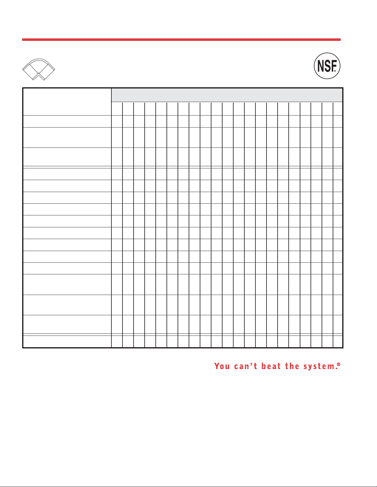
PIPE REFERENCE GUIDE
E
D
I
A
N
M
.
S
A
.
.
U
Plastics Technical Manual
Pipe Reference Guide
(Updated October 2008)
Sizes Available
Product
CPVC Schedule 80
ChemDrain® CPVC
Schedule 40 ★
FlowGuard Gold
CPVC CTS SDR 11
PVC Schedule 80
PVC Schedule 40
PVC Schedule 40 DWV ★
PVC Schedule 30
PVC DWV Foam Core ★
PVC Well Casing
PVC SDR 13.5 (PR315)
PVC SDR 21 (PR200)
PVC SDR 26 (PR160)
PVC SDR 35 Sewer Main
Belled-End ★
®
1/43/81/23
/4 111/4 11/2 221/2 3441/2 5661/4 8 1012141516
••••••••••• • •
•• •• • •
••••••
••••••••••• •• •••• •
••••••••• •• •••• •
•••••• •• •••• •
•
•• •• • •••
••••• •••
•
•••••
••• •
••
PVC SDR 35 Sewer Main
Gasketed ★
PVC Foam Core Sewer Main
PS-50 Belled-End ★
ABS DWV Foam Core ★
★
Non-Pressure
Notes:
1. End treatments are Plain and Belled. Consult factory for availability.
2. Lengths are 10 and 20 feet (13 and 20 feet for gasketed sewer main). Consult factory for availability and
non-standard lengths.
3. PVC Schedule 40 Bell End and PVC Well Casing pipe lengths for sizes 4", 41/2", 6", 61/4", and 8" are 20 feet plus the bell
(20 foot laying length).
4. PVC SDR 35 Sewer Main Pipe in 13 foot lengths are 13 feet plus the bell (13 foot laying length).
"You can't beat the system" and ChemDrain are registered trademarks of Charlotte Pipe and Foundry Company.
18
•• •• •
• • ••• •
••
Page 19
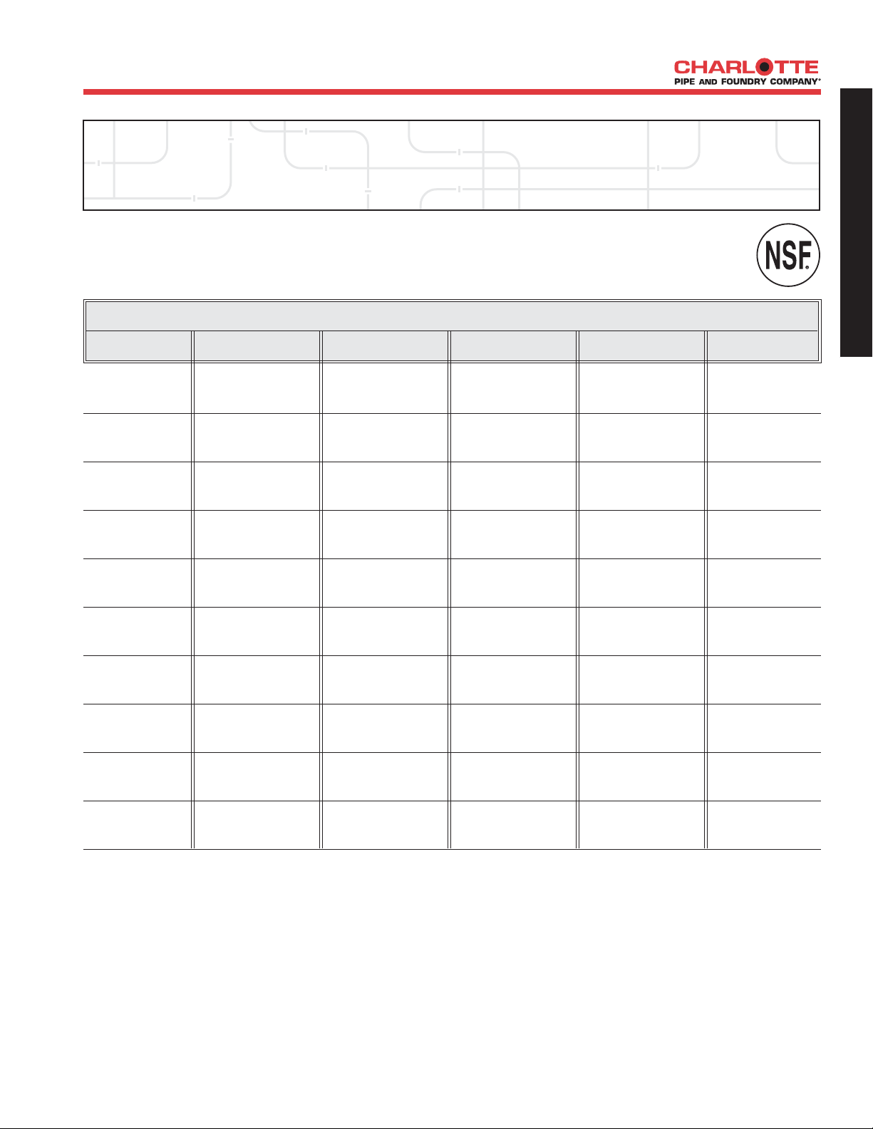
ABS Foam Core DWV Pipe
>> ABS Schedule 40 DWV Pipe
ABS SCHEDULE 40 FOAM CORE (BLACK) PLAIN END FOR NON-PRESSURE APPLICATIONS ASTM F 628
PART NO. NOM. SIZE UPC # AVG. OD (IN.) MIN. WALL (IN.) WT. PER
ABS 3112 11/2" x 10' 03132 1.900 0.156 28.1
ABS 3112 11/2" x 20' 03133 1.900 0.156 28.1
PIPE DATA
611942- 100 FT. (LBS.)
G
G
E
E
N
N
E
E
R
R
A
A
L
L
I
I
N
N
F
F
O
O
R
R
M
M
A
A
T
T
I
I
O
O
N
N
ABS 3200 2" x 10' 03134 2.375 0.156 37.7
ABS 3200 2" x 20' 03135 2.375 0.156 37.7
ABS 3300 3" x 10' 03136 3.500 0.218 77.9
ABS 3300 3" x 20' 03137 3.500 0.218 77.9
ABS 3400 4" x 10' 03138 4.500 0.250 111.4
ABS 3400 4" x 20' 03139 4.500 0.250 111.4
ABS 3600 6" x 10' 03140 6.625 0.281 196.2
ABS 3600 6" x 20' 03141 6.625 0.281 196.2
NSF Listed. Meets All Requirements of ASTM F 628.
ABS piping products are not recommended for use with compressed air or gases.
19
Page 20
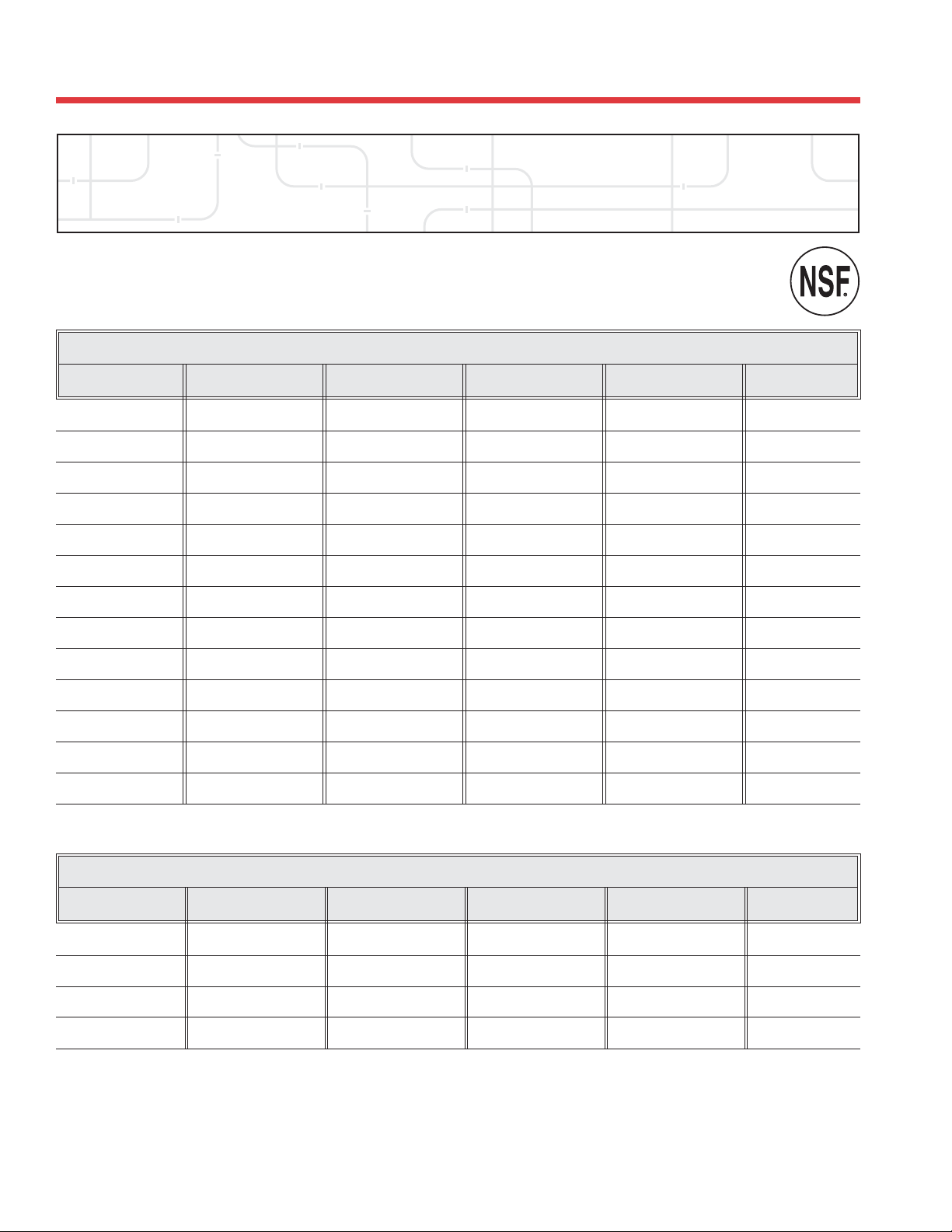
PVC Foam Core DWV Pipe
>> PVC Schedule 40 DWV Pipe
PVC SCHEDULE 40 FOAM CORE (WHITE) PLAIN END FOR NON-PRESSURE APPLICATIONS ASTM F 891
PIPE DATA
Plastics Technical Manual
PART NO. NOM. SIZE UPC # AVG. OD (IN.) MIN. WALL (IN.) WT. PER
PVC 4112 11/2" x 10' 04178 1.900 0.145 38.1
PVC 4112 11/2" x 20' 04177 1.900 0.145 38.1
PVC 4200 2" x 10' 04174 2.375 0.154 51.2
PVC 4200 2" x 20' 04173 2.375 0.154 51.2
PVC 4300 3" x 10' 03934 3.500 0.216 105.0
PVC 4300 3" x 20' 03935 3.500 0.216 105.0
PVC 4400 4" x 10' 03936 4.500 0.237 146.0
PVC 4400 4" x 20' 03937 4.500 0.237 146.0
PVC 4600 6" x 10' 03938 6.625 0.280 247.0
PVC 4600 6" x 20' 03939 6.625 0.280 247.0
PVC 4800 8" x 20' 03941 8.625 0.322 371.0
PVC 4910 10" x 20' 03942 10.750 0.365 566.0
PVC 4912 12" x 20' 03943 12.750 0.406 755.0
611942- 100 FT. (LBS.)
PVC SCHEDULE 40 FOAM CORE (WHITE) BELL-END FOR NON-PRESSURE APPLICATIONS
PART NO. NOM. SIZE UPC # AVG. OD (IN.) MIN. WALL (IN.) WT. PER
PVC 4300B 3" x 20' 04782 3.500 0.216 105.0
PVC 4400B 4" x 10' 04783 4.500 0.237 146.0
PVC 4400B 4" x 20' 04784 4.500 0.237 146.0
PVC 4600B 6" x 20' 04786 6.625 0.280 247.0
NOTE: When ordering, please specify plain end or bell-end.
NSF Listed. Meets All Requirements of ASTM F 891.
PVC piping products are not recommended for use with compressed air or gases.
20
611942- 100 FT. (LBS.)
Page 21
PVC Schedule 40 DWV Pipe
>> PVC Schedule 40 DWV Pipe
PVC SCHEDULE 40 (WHITE) PLAIN END PVC 1120 ASTM D 2665
PART NO. NOM. SIZE UPC # AVG. OD (IN.) MIN. WALL (IN.) WT. PER
PIPE DATA
611942- 100 FT. (LBS.)
G
G
E
E
N
N
E
E
R
R
A
A
L
L
I
I
N
N
F
F
O
O
R
R
M
M
A
A
T
T
I
I
O
O
N
N
PVC 7100* 11/4"
PVC 7100* 11/4"
PVC 7112* 11/2"
PVC 7112* 11/2"
x10' 03945 1.660 .140 42.4
x20' 03946 1.660 .140 42.4
x10' 03947 1.900 .145 50.7
x20' 03948 1.900 .145 50.7
PVC 7200* 2"x10' 03949 2.375 .154 68.1
PVC 7200* 2"x20' 03950 2.375 .154 68.1
PVC 4025* 21/2"
x20' 04205 2.875 .203 108.0
PVC 7300* 3"x10' 03951 3.500 .216 141.2
PVC 7300* 3"x20' 03952 3.500 .216 141.2
PVC 7400* 4"x10' 03953 4.500 .237 201.2
PVC 7400* 4"x20' 03954 4.500 .237 201.2
PVC 7500* 5"x20' 04837 5.563 .258 272.5
PVC 7600* 6"x10' 03955 6.625 .280 353.7
PVC 7600* 6"x20' 03956 6.625 .280 353.7
PVC 7800* 8"x20' 03958 8.625 .322 532.3
PVC 7910* 10"x20' 03959 10.750 .365 754.7
PVC 7912* 12"x20' 03961 12.750 .406 997.9
PVC 7914* 14"x20' 04862 14.000 .437 1180.1
PVC 7916* 16"x20' 04918 16.000 .500 1543.1
* Dual Marked ASTM D 1785 & ASTM D 2665.
NSF Listed. Meets All Requirements of ASTM D 1784, ASTM D 1785, and ASTM D 2665.
PVC piping products are not recommended for use with compressed air or gases.
21
Page 22
PVC Pipe: Schedule 40
>> PVC Schedule 40 Pipe - Plain End
PVC SCHEDULE 40 (WHITE) PLAIN END PVC 1120 ASTM D 1785
PART NO. NOM. SIZE UPC # AVG. OD (IN.) MIN. WALL (IN.) PRESSURE WT. PER
PVC 4005
PVC 4005
PVC 4007
PVC 4007
PVC 4010 1"x10' 06664 1.315 .133 450 PSI 31.3
PVC 4010 1"x20' 03928 1.315 .133 450 PSI 31.3
PVC 7100* 11/4"x10' 03945 1.660 .140 370 PSI 42.4
PVC 7100* 11/4"x20' 03946 1.660 .140 370 PSI 42.4
PVC 7112* 11/2"x10' 03947 1.900 .145 330 PSI 50.7
PVC 7112* 11/2"x20' 03948 1.900 .145 330 PSI 50.7
PVC 7200* 2"x10' 03949 2.375 .154 280 PSI 68.1
PVC 7200* 2"x20' 03950 2.375 .154 280 PSI 68.1
PVC 4025* 21/2"x20' 04205 2.875 .203 300 PSI 108.0
PVC 7300* 3"x10' 03951 3.500 .216 260 PSI 141.2
PVC 7300* 3"x20' 03952 3.500 .216 260 PSI 141.2
PVC 7400* 4"x10' 03953 4.500 .237 220 PSI 201.2
PVC 7400* 4"x20' 03954 4.500 .237 220 PSI 201.2
PVC 7500* 5"x20' 04837 5.563 .258 190 PSI 272.5
PVC 7600* 6"x10' 03955 6.625 .280 180 PSI 353.7
PVC 7600* 6"x20' 03956 6.625 .280 180 PSI 353.7
PVC 7800* 8"x20' 03958 8.625 .322 160 PSI 532.3
PVC 7910* 10"x20' 03959 10.750 .365 140 PSI 754.7
PVC 7912* 12"x20' 03961 12.750 .406 130 PSI 997.9
PVC 7914
PVC 7916
*
*
1
/2"x10' 06658 .840 .109 600 PSI 15.9
1
/2"x20' 03922 .840 .109 600 PSI 15.9
3
/4"x10' 06661 1.050 .113 480 PSI 21.1
3
/4"x20' 03925 1.050 .113 480 PSI 21.1
14"x20' 04862 14.000 .437 130 PSI 1180.1
16"x20' 04918 16.000 .500 130 PSI 1543.1
611942- AT 23° C OR 73° F 100 FT. (LBS.)
PIPE DATA
Plastics Technical Manual
MAX WORK
* Dual marked ASTM D 1785 and ASTM D 2665.
NOTE: When ordering, please specify plain end or bell end.
NSF Listed. Meets All Requirements of ASTM D 1784 and ASTM D 1785.
PVC piping products are not recommended for use with compressed air or gases.
All Charlotte Pipe and Foundry Company Products are made in U.S.A.
22
Page 23
PIPE DATA
>> PVC Schedule 40 Pipe - Bell End*
PVC SCHEDULE 40 (WHITE) BELL END PVC 1120 ASTM D 1785
PART NO. NOM. SIZE UPC # AVG. OD (IN.) MIN. WALL (IN.) PRESSURE BELL DEPTH WT. PER
PVC 4005B**
PVC 4005B**
PVC 4007B**
PVC 4007B**
1
/2"
x10' 04986 .840 .109 600 PSI 2.00 15.9
1
/2"
x20' 03923 .840 .109 600 PSI 2.00 15.9
3
/4"
x10' 04987 1.050 .113 480 PSI 2.25 21.1
3
/4"
x20' 03926 1.050 .113 480 PSI 2.25 21.1
PVC 4010B** 1"x10' 04988 1.315 .133 450 PSI 2.50 31.3
PVC 4010B** 1"x20' 03929 1.315 .133 450 PSI 2.50 31.1
PVC 4012B§ 11/4"
PVC 4012B§ 11/4"
PVC 4015B§ 11/2"
PVC 4015B§ 11/2"
x10' 04989 1.660 .140 370 PSI 2.75 42.4
x20' 03930 1.660 .140 370 PSI 2.75 42.4
x10' 04990 1.900 .145 330 PSI 3.00 50.7
x20' 03931 1.900 .145 330 PSI 3.00 50.7
PVC 4020B† 2"x10' 04991 2.375 .154 280 PSI 4.00 69.2
PVC 4020B† 2"x20' 03932 2.375 .154 280 PSI 4.00 69.2
PVC 4025B‡ 21/2"
x10' 04992 2.875 .203 300 PSI 4.00 110.0
611942- AT 23° C OR 73° F (IN.) 100 FT. (LBS.)
MAX WORK
G
E
N
E
R
A
L
I
N
F
O
R
M
A
T
I
O
N
PVC 4025B‡ 21/2"
x20' 04206 2.875 .203 300 PSI 4.00 110.0
PVC 7300B§ 3"x10' 04853 3.500 .216 260 PSI 4.00 145.1
PVC 4030B† 3"x20' 03933 3.500 .216 260 PSI 4.00 144.5
PVC 7400B§ 4"x10' 04835 4.500 .237 220 PSI 4.00 207.9
PVC 9400B† 4"x20' 03964 4.500 .237 220 PSI 5.00 206.2
PVC 7600B§ 6"x10' 04850 6.625 .280 180 PSI 6.50 371.4
PVC 9600B† 6"x20' 03965 6.625 .280 180 PSI 6.50 365.5
PVC 7800B† 8"x10' 09903 8.625 .322 160 PSI 7.00 556.9
PVC 9800B† 8"x20' 03967 8.625 .322 160 PSI 7.00 552.3
PVC 7910B† 10"x10' 00990 10.750 .365 140 PSI 9.00 791.9
PVC 7910B† 10"x20' 03960 10.750 .365 140 PSI 9.00 785.4
PVC 7912B† 12"x20' 03962 12.750 .406 130 PSI 10.00 1046.7
PVC 7914B† 14"x20' 04863 14.000 .437 130 PSI 10.00 1180.1
PVC 7916B† 16"x20' 04929 16.000 .500 130 PSI 10.00 1543.1
* Bell dimensions meet either ASTM D 2672 or § Dual Marked ASTM D 1785 & ASTM D 2665
ASTM F 480, depending upon pipe diameter † Triple Marked ASTM D 1785 & ASTM D 2665 & ASTM F 480
** ASTM D 1785 ‡ Dual Marked ASTM D 1785 & ASTM F 480
PVC piping products are not recommended for use with compressed air or gases.
23
Page 24
>> PVC Well Casing
PVC SCHEDULE 40 (WHITE) BELL END WELL CASING PVC 1120 ASTM F 480
PIPE DATA
Plastics Technical Manual
PART NO. NOM. SIZE UPC # AVG. OD (IN.) MIN. WALL (IN.) BELL DEPTH WT. PER
PVC 4020B 2"x20' 03932 2.375 .154 4.00 69.2
PVC 4025B 21/2"
PVC 4030B 3"x20' 03933 3.500 .216 4.00 144.5
PVC 9400B 4"x20' 03964 4.500 .237 5.00 206.2
PVC 9600B 6"x20' 03965 6.625 .280 6.50 365.5
PVC 9800B 8"x20' 03967 8.625 .322 7.00 552.3
SDR 17 and DR 27.6 BELL END WELL CASING PVC 1120 ASTM F 480
PART NO. NOM. SIZE UPC # AVG. OD (IN.) MIN. WALL (IN.) BELL DEPTH WT. PER
PVC 9450B 41/2"
PVC 9625B 61/4"
>> PVC SDR Pipe
PR 200 PVC 1120 BELL END ASTM D 2241 SDR 21
PART NO. NOM. SIZE UPC # AVG. OD (IN.) MIN. WALL (IN.) PRESSURE BELL DEPTH WT. PER
PVC 23155B *1/2"
PVC 20007B
PVC 20007B
611942- (IN.) 100 FT. (LBS.)
x20' 04206 2.875 .203 4.00 110.0
611942- (IN.) 100 FT. (LBS.)
x20' 04159 SDR 17 4.950 .291 5.50 278.4
x20' 03966 DR 27.6 6.900 .250 7.00 342.7
MAX WORK
611942- AT 23° C OR 73° F (IN.) 100 FT. (LBS.)
x20' 03991 .840 .062 315 PSI 2.00 10.0
3
/4"
x10' 10742 1.050 .060 200 PSI 2.25 11.8
3
/4"
x20' 03984 1.050 .060 200 PSI 2.25 11.8
PVC 20010B 1"x20' 03986 1.315 .063 200 PSI 2.50 15.7
PVC 20012B 11/4"
PVC 20015B 11/2"
x20' 03987 1.660 .079 200 PSI 2.75 24.9
x20' 03988 1.900 .090 200 PSI 3.00 32.4
PVC 20020B 2"x20' 03989 2.375 .113 200 PSI 4.00 50.9
*PR 315 / SDR 13.5
PR 160 PVC 1120 BELL END ASTM D 2241 SDR 26
PART NO. NOM. SIZE UPC # AVG. OD (IN.) MIN. WALL (IN.) PRESSURE BELL DEPTH WT. PER
PVC 16012B 11/4"
PVC 16015B 11/2"
x20' 04211 1.660 .064 160 PSI 2.75 20.3
x20' 04210 1.900 .073 160 PSI 3.00 26.6
611942- AT 23° C OR 73° F (IN.) 100 FT. (LBS.)
MAX WORK
PVC 16020B 2"x20' 04212 2.375 .091 160 PSI 4.00 41.4
PVC 16030B 3"x20' 04222 3.500 .135 160 PSI 4.00 92.3
NOTE: When ordering, please specify plain end or bell end.
PVC piping products are not recommended for use with compressed air or gases.
E
D
I
A
N
M
.
S
A
.
.
U
24
Page 25
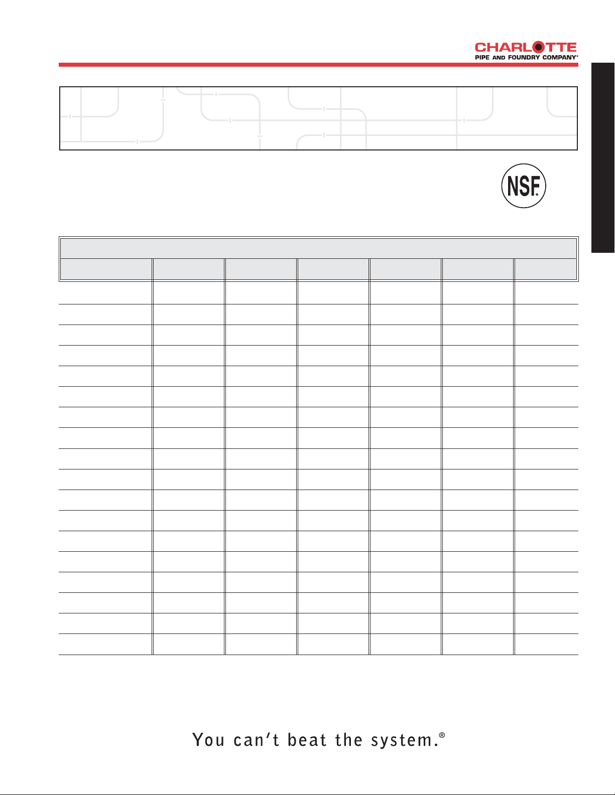
PIPE DATA
PVC Schedule 80 Pipe
>> PVC Schedule 80 Pipe, Type 1, Grade 1 - Plain End
PVC SCHEDULE 80 (GRAY) PLAIN END PVC 1120
PART NO. NOM. SIZE UPC # AVG. OD (IN.) MIN. WALL (IN.) PRESSURE WT. PER
PVC 10002
1
/4"x20' 04920 0.540 .119 1130 PSI 10.0
611942- AT 23° C OR 73° F 100 FT. (LBS.)
ASTM D 1784 & ASTM D 1785
MAX WORK
G
E
N
E
R
A
L
I
N
F
O
R
M
A
T
I
O
N
PVC 10003
PVC 10005
PVC 10007
3
/8"x20' 04917 0.675 .126 920 PSI 13.8
1
/2"x20' 03968 0.840 .147 850 PSI 20.3
3
/4"x20' 03969 1.050 .154 690 PSI 27.5
PVC 10010 1"x20' 03970 1.315 .179 630 PSI 40.5
PVC 10012 11/4"x20' 03973 1.660 .191 520 PSI 55.9
PVC 10015 11/2"x20' 03976 1.900 .200 470 PSI 67.7
PVC 10020 2"x20' 03977 2.375 .218 400 PSI 93.6
PVC 10025 21/2"x20' 03978 2.875 .276 420 PSI 142.8
PVC 10030 3"x20' 03979 3.500 .300 370 PSI 191.1
PVC 10040 4"x20' 03980 4.500 .337 320 PSI 279.3
PVC 10050 5"x20' 04831 5.563 .375 290 PSI 387.3
PVC 10060 6"x20' 03981 6.625 .432 280 PSI 532.7
PVC 10080 8"x20' 04175 8.625 .500 250 PSI 808.9
PVC 10100 10"x20' 04768 10.750 .593 230 PSI 1199.3
PVC 10120 12"x20' 04770 12.750 .687 230 PSI 1650.1
PVC 10140 14"x20' 04816 14.000 .750 220 PSI 1930.0
PVC 10160 16"x20' 04919 16.000 .843 220 PSI 2544.1
NSF Listed. Meets All Requirements of ASTM D 1784 and ASTM D 1785.
PVC piping products are not recommended for use with compressed air or gases.
25
Page 26
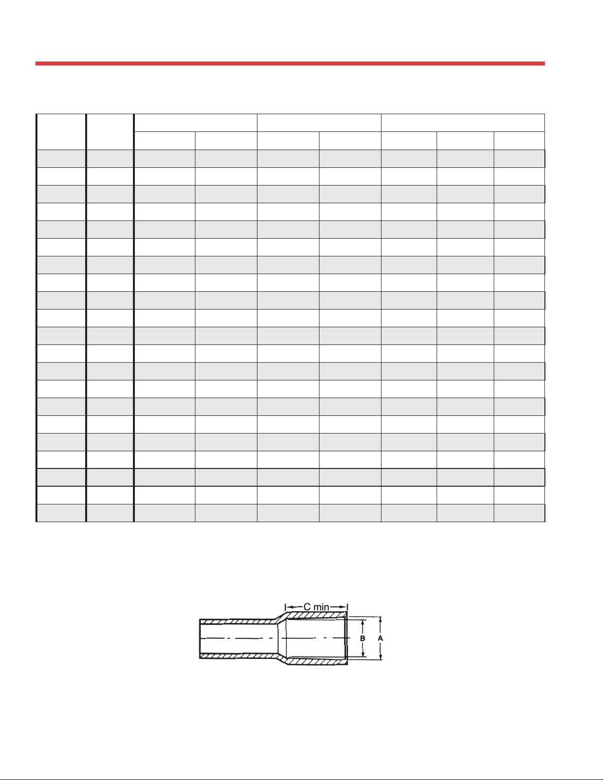
BELLED-END PIPE DIMENSIONS
Socket Dimensions For Belled-End Pipe
Plastics Technical Manual
NOM.
Pipe size
ASTM
Standard
I.D. Min. I.D. Max. I.D. Min. I.D. Max. SDR Schedule 40 Schedule 80
SOCKET LENGTH (C)SOCKET BOTTOM (B)SOCKET ENTRANCE (A)
1/2 D 2672 .844 0.852 0.832 0.840 2.000 2.000 1.000
3/4 D 2672 1.054 1.062 1.042 1.050 2.250 2.250 1.250
1 D 2672 1.320 1.330 1.305 1.315 2.500 2.500 1.500
1 1/4 D 2672 1.665 1.675 1.650 1.660 2.750 2.750 1.750
1 1/2 D 2672 1.906 1.918 1.888 1.900 3.000 3.000 2.000
2 D 2672 2.381 2.393 2.357 2.369 4.000 — 2.250
2 F 480 2.380 2.392 2.357 2.369 — 4.000 —
2 1/2 D 2672 2.882 2.896 2.854 2.868 4.000 — 2.500
2 1/2 F 480 2.880 2.894 2.854 2.868 — 4.000 —
3 D 2672 3.508 3.524 3.476 3.492 4.000 — 3.250
3 F 480 3.506 3.522 3.476 3.492 — 4.000 —
4 D 2672 4.509 4.527 4.473 4.491 5.000 — 4.000
4 F 480 4.508 4.526 4.473 4.491 — 5.000 —
6 D 2672 6.636 6.658 6.592 6.614 6.500 — 6.000
6 F 480 6.637 6.659 6.592 6.614 — 6.500 —
8 D 2672 8.640 8.670 8.583 8.613 — — 6.000
8 F 480 8.634 8.664 8.583 8.613 — 7.000 —
10 D 2672 10.761 10.791 10.707 10.737 — 9.000 7.500
12 D 2672 12.763 12.793 12.706 12.736 — 10.000 8.500
14 D 2672 14.020 14.050 13.970 14.000 — 10.000 9.000
16 D 2672 16.030 16.060 15.965 15.995 — 10.000 —
Note: All dimensions are in inches.
26
Page 27
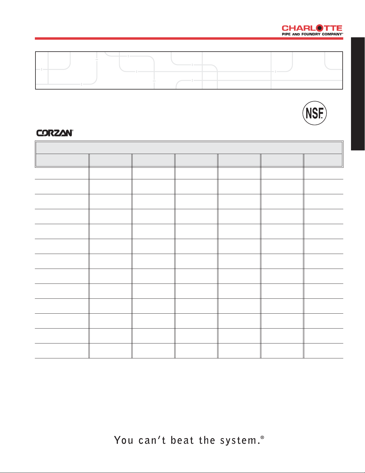
OUTSIDE DIAMETER AND
THICKNESS
CPVC Schedule 80 Pipe
>> CPVC Schedule 80 Pipe, Type IV, Grade 1
CPVC SCHEDULE 80 (LIGHT GRAY) PLAIN END CPVC 4120
PART NO. NOM. SIZE UPC # AVG. OD (IN.) MIN. WALL (IN.) PRESSURE WT. PER
611942- AT 23° C OR 73° F 100 FT. (LBS.)
ASTM D 1784 & ASTM F 441
MAX WORK
G
E
N
E
R
A
L
I
N
F
O
R
M
A
T
I
O
N
CPV 11002
CPV 11003
CPV 11005
CPV 11007
CPV 11010 1"x20' 04789 1.315 .179 630 PSI 44.2
CPV 11012 11/4"x20' 04790 1.660 .191 520 PSI 61.0
CPV 11015 11/2"x20' 04791 1.900 .200 470 PSI 73.9
CPV 11020 2"x20' 04792 2.375 .218 400 PSI 102.2
CPV 11025 21/2"x20' 04793 2.875 .276 420 PSI 155.9
CPV 11030 3"x20' 04794 3.500 .300 370 PSI 208.6
CPV 11040 4"x20' 04795 4.500 .337 320 PSI 304.9
CPV 11060 6"x20' 04796 6.625 .432 280 PSI 581.5
1
/4"x20' 04931 .540 .119 1130 PSI 10.9
3
/8"x20' 04943 .675 .126 920 PSI 15.0
1
/2"x20' 04787 .840 .147 850 PSI 22.1
3
/4"x20' 04788 1.050 .154 690 PSI 30.0
CPV 11080 8"x20' 04797 8.625 .500 250 PSI 882.9
NSF Listed. Meets All Requirements of ASTM D 1784 and ASTM F 441.
CPVC piping products are not recommended for use with compressed air or gases.
Corzan is a registered trademark of The Lubrizol Corporation.
27
Page 28
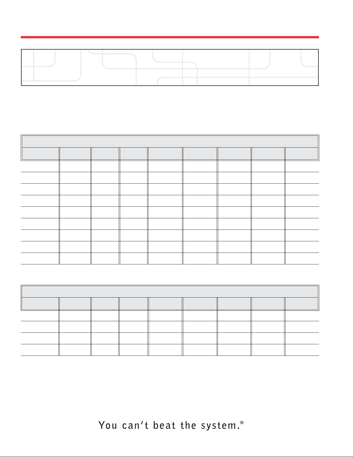
PIPE DATA
PVC Sewer Pipe
Plastics Technical Manual
>>PVC SDR 35 PSM Pipe
SDR-35 GASKETED - PS 46
PART NO. NOM. SIZE UPC # QTY. PER PERCENT LAYING WT. PER AVG. OD (IN.) MIN. WALL (IN.)
S/M 6004G 4"x13' 04011 780 4.763 13'-0
S/M 6004G 4"x20' 04012 1200 7.144 20'-0
S/M 6006G 6"x13' 04015 364 4.763 13'-0
S/M 6006G 6"x20' 04016 560 8.330 20'-0
S/M 6008G 8"x13' 04020 130 3.330 13'-0
S/M 6008G 8"x20' 04021 200 5.000 20'-0
S/M 6010G 10"x13' 04023 104 4.160 13'-0
S/M 6012G 12"x13' 04026 78 4.763 13'-0
S/M 6015G 15"x13' 04029 78 5.550 13'-0
Weight is approximate and is for shipping purposes only.
SDR-35 SOLVENT WELD - PS 46
PART NO. NOM. SIZE UPC # QTY. PER PERCENT LAYING WT. PER AVG. OD (IN.) MIN. WALL (IN.)
611942- SKID PER SKID LENGTH 100 FT. (LBS.)
611942- SKID PER SKID LENGTH 100 FT. (LBS.)
TRUCKLOAD
TRUCKLOAD
ASTM D 3034 & ASTM F 477
"
"
"
"
"
"
"
"
"
110.4 4.215 .120
109.7 4.215 .120
249.6 6.275 .180
247.0 6.275 .180
451.0 8.400 .240
442.7 8.400 .240
709.0 10.500 .300
1024.9 12.500 .360
1523.2 15.300 .437
S/M 6004 4"x10' 04008 600 4.160 10'-0
S/M 6004 4"x20' 04009 1200 7.144 20'-0
S/M 6006 6"x10' 04013 280 4.160 10'-0
S/M 6006 6"x20' 04014 560 8.330 20'-0
Weight is approximate and is for shipping purposes only.
NOTE: For truckloads of mixed sizes, multiply skids desired by truckload percent per skid.
Meets All Requirements of ASTM D 3034.
SDR 35 Gaskets meet or exceed ASTM F 477. Gasketed joints meet ASTM D 3212.
Sewer pipe is not pressure rated and should not be used for pressure systems.
PVC piping products are not recommended for use with compressed air or gases.
28
"
"
"
"
112.0 4.215 .120
109.7 4.215 .120
252.0 6.275 .180
246.0 6.275 .180
Page 29
PIPE DATA
PVC Foam Core Sewer Pipe
>> PVC Foam Core Gravity Sewer Pipe - PS 50/Sewer and Drain Series
SOLVENT WELD ASTM F 891
PART NO. NOM. SIZE UPC # QTY. PER PERCENT AVG. OD (IN.) MIN. WALL (IN.) WT. PER
S/M 5400 4"x10' 04002 600 4.160 4.215 .124 82.8
611942- SKID PER SKID 100 FT. (LBS.)
TRUCKLOAD
G
E
N
E
R
A
L
I
N
F
O
R
M
A
T
I
O
N
S/M 5400 4"x20' 04003 1200 7.144 4.215 .124 82.8
S/M 5600 6"x10' 04004 280 4.160 6.275 .185 167.0
S/M 5600 6"x20' 04005 560 8.330 6.275 .185 167.0
Weight is approximate and is for shipping purposes only.
NOTE: For truckloads of mixed sizes, multiply skids desired by truckload percent per skid.
Pipe listed in this section meets or exceeds the requirements of ASTM F 891 PS 50 Series.
Sewer pipe is not pressure rated and should not be used for pressure systems.
PVC piping products are not recommended for use with compressed air or gases.
29
Page 30

PRESSURE/TEMPERATURE
RELATIONSHIP
Plastics Technical Manual
The operating pressure of PVC and CPVC pipe will be reduced as the operating temperature increases
above 73° F. To calculate this reduction, multiply the operating pressures shown on the previous pages by
the correction factors shown below:
Operating Correction Factors
Temperature (°F) PVC CPVC
73 1.00 1.00
80 .88 1.00
90 .75 .91
100 .62 .82
110 .50 .77
120 .40 .65
130 .30 .62
140 .22 .50
150 NR .47
160 NR .40
170 NR .32
180 NR .25
200 NR .20
For example, the operating pressure for 6" Schedule 80 CPVC pipe is 280 psi. If the operating temperature
is 140° F, the maximum operating pressure is now 140 psi (280 x .50).
Note: Operating temperatures above 140° F for PVC and 180° F for SDR 11 FlowGuard Gold® and 200°
F for CPVC schedule 80 piping products are not recommended.
Pressure ratings shown are for socket (solvent cement) systems. The system must always be de-rated to the
pressure rating of the lowest rated system component at the expected maximum system operating
temperature. For pressure ratings of flanges or unions, see the information on those components elsewhere
in this technical manual. Pressure ratings of molded or cut threads are 50% of solvent cement systems. For
pressure ratings of valves or other system components, always consult the technical recommendations
from the manufacturers of those products.
Low Temperature Recommendation
Like most materials, PVC and CPVC become more brittle at low temperatures, particularly at temperatures below freezing
(32°F). Charlotte Pipe and Foundry recommends taking proper precautions when installing systems at low temperatures includ-
ing providing proper insulation. If a system is designed to operate at temperatures below freezing (32ºF), Charlotte Pipe
recommends the following:
1. Reduce water hammer pressure surges to a minimum by:
a. Using only slow acting solenoid valves, if any;
b. Reducing pump start-up pressure surges with slow start-up motors and rubber expansion devices;
c. Not exceeding a maximum fluid velocity of 5-feet per second.
2. Provide more than minimum Charlotte Pipe recommended support spacing.
3. Thrust blocking at branches, changes in direction and end of runs.
4. Use expansion/contraction devices when temperature changes occur in runs.
5. Strictly follow chemical resistance recommendations.
6. Protect piping from UV, if applicable.
30
Page 31
FLUID FLOW PROPERTIES
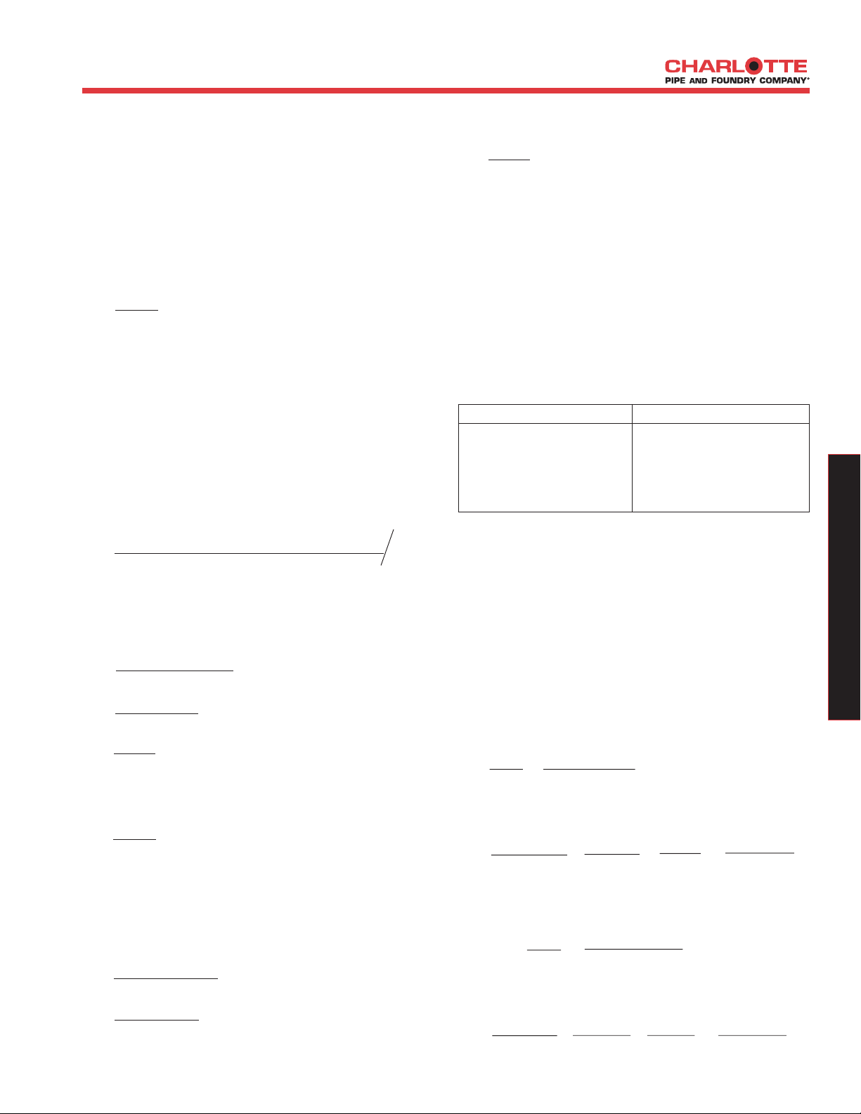
Gravity Flow
Fluid velocity, pipe size and hydraulic slope for
gravity drainage can be determined using the
Manning "N" value. This coefficient relates to the
interior wall smoothness of pipe and is used for
liquids with a steady flow, at a constant depth, in a
prismatic open channel. The Manning's equation is
shown below:
2/3
2/3
S
S
1/2
1/2
2/3
(0.0208)
1/2
V =1.486 R
N
Where:
V =Velocity of flow, ft./second
N = Manning's value
r =hydraulic radius, ft. obtained by dividing the
cross sectional area of flow by the wetted
perimeter of the pipe in contact with the flow.
R is a special case for v with pipes either 1/2
full or full:
R= Inside diameter / 4, in feet
S =
Upstream elevation - Down stream elevation (ft./ft.)
pipe length
Example 1:
2" diameter schedule 40 PVC,
flowing full 30 foot pipe run, 7.5 inch drop
S = 17.5"-10.0" / 12" = 0.0208 ft./ft.
30 ft.
R =2.067" / 12" = 0.043 ft.
4
V =1.486 R
N
Manning's
"N" value is generally accepted as 0.009 for
Designing gravity sewer systems
V =1.486 (0.043)
0.009
V =2.9 ft./second
Assume "N" to be 0.010
V =1.486 (0.0839)
2/3
(0.0125)
1/2
0.010
V =3.2 ft./second
It is widely recommended that the flow velocity in
sanitary sewer systems to be equal to or greater
than 2.0 feet per second for self cleaning drain lines.
Laboratory tests have shown that the “N” value for
ABS and PVC pipe ranges from .008 to .012. The
table below shows “N” values for other piping
materials.
“N” Values For Typical Piping Materials
Piping Material “N” Values
Cast Iron .011 - .015
Finished Concrete .011 - .015
Unfinished Concrete .013 - .017
Corrugated Metal .021 - .027
Glass .009 - .013
Clay .011 - .017
Fluid Flow Rate
Calculation of Volume Flow Rate:
Where:
Q =aV
a = Cross sectional area of flow, ft.
V =Flow Velocity, ft/sec
Q =
Volume flow rate, ft3/sec
Example 1:
2" Schedule 40 PVC
a=πDi2 = π (2.067/12)2 = 0.0233 ft
4 4
V =2.9 ft/sec
Q = 0.0233 x 2.9 = 0.0676 ft3/sec
Q = 0.0676 ft3 x 7.48 gal x 60 sec = 30.3 gals
sec ft3 min min
2
2
D
E
S
I
G
N
&
E
N
G
I
N
E
E
R
I
N
G
D
A
T
A
Example 2:
4" diameter schedule 40 ABS, flowing 1/2 full
10 foot pipe run, 1.5 inch drop
S=20"-18.5" / 12" = 0.0125 ft./ft.
10 ft.
R =4.026" / 12" = 0.0839 ft.
4
Example 2:
4" Schedule 40 PVC
a = 1/2 ( πDi
2
= π (4.026/12)2 = 0.0442 ft
)
4 2 x 4
V =3.2 ft/sec
Q = 0.0442 x 3.2 = 0.141 ft3/sec
Q = 0.141 ft3 x 7.48 gal x 60 sec = 63.5 gals
sec ft3 min min
2
31
Page 32
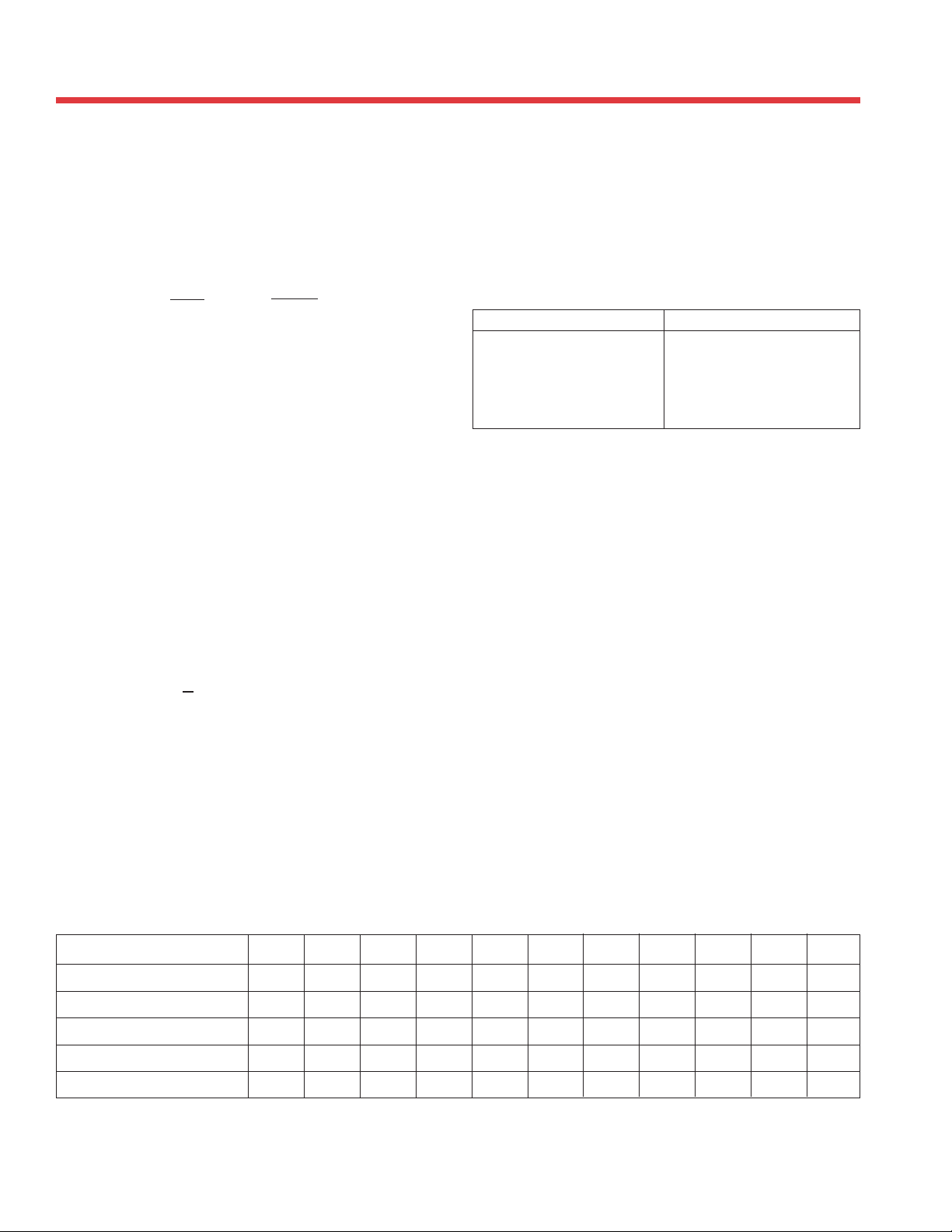
FLUID FLOW PROPERTIES
Plastics Technical Manual
Pressure Flow
Friction loss through PVC pipe is normally obtained
by using the Hazen-Williams equation shown below
for water:
f = 0.2083 x (100)
1.852
x Q
C di
Where:
f =friction head loss in feet of water per 100 feet
of pipe
C = constant for inside pipe roughness (C = 150
for ABS and PVC pipe)
Q = flow in U.S. gallons per minute
di = inside diameter of pipe in inches
Water Velocities
Water velocities in feet per second may be calculated
as follows:
V = 0.408709
di
Q
2
1.852
4.8655
Manning Roughness Factor
(“N” Value)
Laboratory tests have shown that the “N” value for
ABS and PVC pipe ranges from .008 to .012. The
table below shows “N” values for other piping
materials.
“N” Values For Typical Piping Materials
Piping Material “N” Values
Cast Iron .011 - .015
Finished Concrete .011 - .015
Unfinished Concrete .013 - .017
Corrugated Metal .021 - .027
Glass .009 - .013
Clay .011 - .017
Friction Loss Through Fittings
The friction loss through fittings is considered to be
equivalent to the loss through a certain number of
linear feet of pipe of the same diameter as the
fittings. To determine the loss through a piping
system, add together the number of “equivalent feet”
calculated for the fittings in the system.
The chart below shows approximate friction losses,
in equivalent feet, for a variety of ABS and PVC
fittings of different sizes.
Where:
V =velocity in feet per second
Q = flow in U.S. gallons per minute
di = inside diameter of pipe in inches
Approximate Friction Loss For ABS and PVC Fittings In Equivalent Feet Of Straight Pipe
Fitting
Tee (Run) 1.0 1.4 1.7 2.3 2.7 4.3 5.1 6.2 8.3 12.5 16.5
Tee (Branch) 4.0 5.0 6.0 7.3 8.4 12.0 15.0 16.4 22.0 32.7 49.0
90° Elbow 1.5 2.0 2.5 3.8 4.0 5.7 6.9 7.9 12.0 18.0 22.0
45° Elbow .80 1.1 1.4 1.8 2.1 2.6 3.1 4.0 5.1 8.0 10.6
Male/Female Adapter 1.0 1.5 2.0 2.75 3.5 4.5 5.5 6.5 9.0 14.0 —
The table on page 37 shows friction heads in feet and friction losses in psi for schedule 40 pipe. It also shows the gallons per
minute (GPM) and velocities (in feet per second) for various pipe sizes.
32
1
/2
3
"
/4
"
1
"
11/4
"
11/2
"
2
"
21/2
"
3
"
4
"
6
"
8
"
Page 33

Water Hammer
FLUID FLOW PROPERTIES
Water hammer is a term used to describe the sudden
increase in pressure created by quickly stopping,
starting, or changing the direction of the flow of
fluid in a piping system. Typical actions which cause
water hammer are:
(1) Quickly closing a valve.
(2) Quickly opening a valve.
(3) Starting pumps with an empty discharge line.
(4) A high speed wall of liquid (such as starting a
pump) suddenly changes direction (such as going
through a 90° elbow).
(5) Moving entrapped air through the system.
The pressure increase generated must be added to
the fluid pressure already existing in the piping
system to determine the total pressure the system
must withstand. If water hammer is not accounted
for, the sudden pressure surge could be enough to
burst the pipe, or break the fittings or valves.
How To Use The Nomograph On The
Following Page:
Taking the following measures will help prevent
problems:
(1) Keep fluid velocities under 5 feet per second.
(2) Use actuated valves with controlled opening and
closing speeds.
(3) Instruct operators of manual valves on the
proper opening and closing speeds.
(4) When starting a pump, partially close the valve
in the discharge line to minimize the volume of
liquid accelerating through the system. Fully
open the valve after the line is completely filled.
(5) Use a check valve in the pipe line, near the pump,
to keep the line full.
(6) Use air relief valves to control the amount of
air that is admitted or exhausted throughout the
piping system.
(7) Design the piping system so that the total
pressure (operating plus water hammer surge)
does not exceed the pressure rating of the lowest
rated component in the system.
D
E
S
I
G
N
&
E
N
G
I
N
E
E
R
I
N
G
D
A
T
A
1. Liquid Velocity (feet/second), pipeline length
(feet), and valve closing time (seconds) must be
known.
2. Place a straight edge on the liquid velocity in
pipe (line A) and the pipeline length (line D).
3. Mark intersection of straight edge with pivot
line (line C).
4. Place straight edge on mark just placed on pivot
line (line C) and on valve closing time for valve
being used (line A).
5. The intersection of the straight edge with the
pressure increase line (line B) is the liquid
momentum surge pressure (water hammer).
The liquid momentum surge pressure should be
added to the operating line pressure to determine
the system’s maximum line pressure. The maximum
line pressure is used to select the proper pipe
schedule or wall thickness.
The nomograph is based on the formula
P =
0.070VL
T
where P is increase in pressure due to momentum
surge in psi, L is pipeline length in feet, V is liquid
velocity in feet per second, and T is valve closing
time in seconds.
33
Page 34
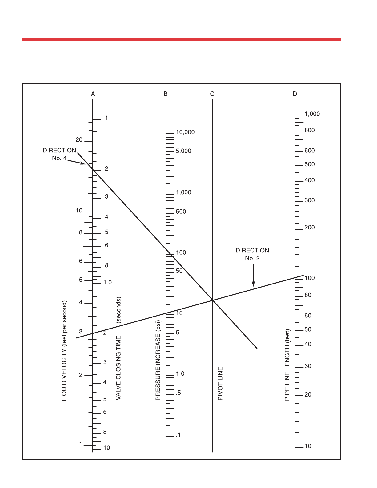
FLUID FLOW PROPERTIES
Water Hammer Nomograph
Plastics Technical Manual
34
Page 35

Entrapped Air
FLUID FLOW PROPERTIES
Source
There are many potential sources for air in pipelines.
Air may be introduced at the point where fluid enters
the system or during initial filling of the system.
Problem
Air in a piping system tends to accumulate at high
points in the system. As the flowrate increases, the
entrapped air is forced along the pipeline by the
moving water. These pockets of air cause flow
restrictions reducing the efficiency and performance
of the system. Water is about 5 times more dense
than air at 100 psi, so when a pocket of air reaches
an outlet, it escapes rapidly and water rushes to
WEATHERING
UV Exposure
PVC and CPVC pipe can suffer surface discoloration
when exposed to ultraviolet (UV) radiation from
sunlight. UV radiation affects PVC and CPVC when
energy from the sun causes excitation of the
molecular bonds in the plastic. The resulting reaction
occurs only on the exposed surface of the pipe and
to the extremely shallow depths of .001 to .003
inches. The effect does not continue when exposure
to sunlight is terminated.
A two-year study was undertaken to quantify the
effects of UV radiation on the properties of PVC
pipe (See Uni-Bell's UNI-TR-5). The study found
that exposure to UV radiation results in a change
in the pipe's surface color and a reduction in impact
strength. Other properties such as tensile strength
(pressure rating) and modulus of elasticity (pipe
stiffness) are not adversely affected.
replace the void. Such pressure surges can easily
exceed the strength of a piping system and it’s
components.
Solution
Designers should be concerned about entrapped air,
but the issue of entrapped air is very complex. The
behavior of air in a piping system is not easy to
analyze, but the effects can be devastating.
Obviously, the best way to reduce problems would
be to prevent air from entering the system. Systems
should be filled slowly and air vented from the high
points before the system is pressurized. Additionally,
air relief valves should be installed at high points in
the system to vent air that accumulates during
service.
The presence of an opaque shield between the sun
and the pipe prevents UV degradation. UV radiation
will not penetrate thin shields such as paint coatings
or wrappings. Burial of PVC pipe provides complete
protection against UV attack.
The most common method used to protect above
ground PVC pipe from the sun is painting with a
latex (water base) paint. Preparation of the surface
to be painted is very important. The pipe should be
cleaned to remove moisture, dirt, and oil and wiped
with a clean, dry cloth. Petroleum-based paints
should not be used, since the presence of petroleum
will prevent proper bonding of paint to pipe.
Reference Uni-Bell PVC Pipe Association 2001
D
E
S
I
G
N
&
E
N
G
I
N
E
E
R
I
N
G
D
A
T
A
35
Page 36
Friction Loss
Pounds Per
Square Inch
0.007
0.009
0.013
0.030
0.048
0.074
0.10
0.13
0.17
0.22
0.26
0.37
0.49
0.55
0.62
0.78
0.94
1.43
2.00
2.67
3.41
5.17
Friction Head
Feet
Velocity
Feet Per Second
Friction Loss
Pounds Per
Square Inch
Friction Head
Feet
Velocity
Feet Per Second
Friction Loss
Pounds Per
Square Inch
3 in.
in.
2
/
1
2
0.015
0.021
0.22
0.31
0.016
0.023
0.038
0.051
0.30
0.49
0.029
0.048
0.03
0.07
0.44
0.66
0.039
0.082
0.09
0.19
0.68
1.03
0.091
0.19
0.11
0.88
0.14
0.32
1.37
0.33
0.17
1.10
0.21
0.49
1.71
0.50
0.23
1.33
0.29
0.68
2.05
0.70
0.31
1.55
0.39
0.91
2.39
0.93
0.40
0.50
1.77
1.99
0.50
0.62
1.16
1.44
2.73
3.08
1.19
1.49
0.60
2.21
0.76
1.75
3.42
1.80
0.85
2.65
1.07
2.46
4.10
2.53
1.13
1.28
3.09
3.31
1.42
1.61
3.27
3.71
4.79
5.13
3.36
3.82
1.44
3.53
1.81
4.19
5.47
4.30
1.80
3.98
2.26
5.21
6.15
5.36
2.18
4.42
2.74
6.33
6.84
6.51
3.31
4.63
5.52
6.63
4.15
5.81
9.58
13.41
8.55
10.26
6.16
7.73
7.88
8.83
11.93
11.04
0.012
Friction Head
Feet
Velocity
Feet Per Second
Friction Loss
Pounds Per
Square Inch
Friction Head
Feet
Velocity
Feet Per Second
1
in.
2
/
1
2 in.
0.03
0.07
0.33
0.066
0.11
0.49
0.69
0.09
0.17
0.22
0.38
0.81
1.13
0.21
0.98
0.31
0.72
1.62
0.45
1.46
0.66
1.53
2.42
0.76
1.95
1.13
2.61
3.23
1.15
2.44
1.71
3.95
4.04
1.62
2.93
2.39
5.53
4.85
2.15
3.41
3.19
7.36
5.66
2.75
3.43
3.90
4.39
4.08
5.08
9.43
11.73
6.47
7.27
4.16
5.84
4.88
5.85
6.17
8.65
14.25
19.98
8.08
9.70
7.76
8.82
6.83
7.32
9.94
7.80
12.37
15.03
8.78
9.75
0.012
0.027
10 in.
0.82
12 in.
0.015
0.022
0.035
0.05
1.03
1.23
0.027
1.01
0.028
0.065
1.44
Friction Loss
Pounds Per
Square Inch
Friction Head
Feet
Velocity
Feet Per Second
1
in.
4
/
1
0.06
0.14
0.44
0.19
0.44
1.11
0.35
0.81
1.55
0.67
1.55
2.21
1.42
3.28
3.31
2.42
5.59
4.42
3.66
8.45
5.52
5.13
6.82
11.85
15.76
6.63
7.73
8.74
10.87
20.18
25.10
8.84
9.94
13.21
30.51
11.05
8 in.
0.012
0.015
0.03
0.035
0.65
0.81
0.017
0.024
0.04
0.055
0.97
1.14
0.030
0.048
0.07
0.11
1.30
1.63
0.069
0.16
1.94
Friction Loss
Pounds Per
Square Inch
Friction Head
Feet
Velocity
Feet Per Second
1 in.
0.24
0.55
0.77
0.75
1.72
1.93
1.37
3.17
2.72
2.61
6.02
3.86
5.53
9.42
12.77
21.75
5.79
7.72
14.22
19.95
32.88
46.08
9.65
11.58
6 in.
0.009
0.013
0.02
0.03
0.56
0.67
0.017
0.022
0.04
0.05
0.79
0.84
0.022
0.026
0.05
0.06
0.90
1.01
0.035
0.052
0.08
0.12
1.12
1.41
0.069
0.096
0.16
0.22
1.69
1.97
0.12
0.19
0.28
0.43
2.25
2.81
0.26
0.60
3.37
0.34
0.79
3.94
Friction Loss
Pounds Per
Square Inch
Friction Head
Feet
Velocity
Feet Per Second
0.22
0.44
2.48
4.56
8.68
in.
4
/
0.51
1.02
5.73
3
0.63
1.26
3.16
10.52
20.04
4.43
6.32
18.39
31.32
42.46
72.34
9.48
12.65
5 in.
0.009
0.013
0.02
0.03
0.49
0.57
0.013
0.017
0.03
0.04
0.65
0.73
0.022
0.030
0.05
0.07
0.81
0.97
0.043
0.048
0.10
0.11
1.14
1.22
0.056
0.069
0.13
0.16
1.46
1.30
0.082
0.125
0.19
0.29
1.62
2.03
0.17
0.40
2.44
0.235
0.30
0.54
0.69
2.84
3.25
0.45
1.05
4.06
0.63
1.46
4.87
0.85
1.95
5.69
Friction Loss
Pounds Per
Square Inch
Friction Head
Feet
Velocity
Feet Per Second
Gallons
Per Minute
(Friction head and friction loss are per 100 feet of pipe.) CAUTION: Flow velocity should not exceed 5 feet per second. ABS and PVC pipe cannot be used for compressed air service.
FRICTION LOSS AND FLOW VELOCITY FOR SCHEDULE 40 THERMOPLASTIC PIPE
Flow velocity required to obtain a self cleaning drain, waste, and vent plumbing system is 2.0 to 2.5 feet per second.
0.90
1.80
10.15
in.
2
2.08
4.16
/
1
23.44
1.13
2.26
5.64
1
2
5
18.64
35.51
43.06
82.02
7.90
11.28
7
10
4 in.
15
0.013
0.017
0.03
0.04
0.51
0.64
20
25
0.026
0.035
0.06
0.08
0.77
0.89
30
35
0.048
0.056
0.11
0.13
1.02
1.15
40
45
0.069
0.095
0.16
0.22
1.28
1.53
50
60
0.13
0.15
0.30
0.34
1.79
1.92
70
75
0.16
0.38
2.05
80
0.20
0.47
2.30
90
0.25
0.58
2.56
100
0.38
0.53
0.88
1.22
3.20
3.84
125
150
0.71
1.63
4.48
175
0.90
2.08
5.11
200
1.36
3.15
6.40
250
1.91
4.41
7.67
300
2.55
5.87
8.95
350
36
16 in.
14 in.
0.017
0.022
0.04
0.05
1.16
1.30
0.039
0.048
0.09
0.11
1.64
1.85
0.091
0.12
0.21
0.27
2.27
2.59
0.44
0.55
1.01
1.26
4.49
5.06
1.08
1.34
2.49
3.09
6.50
7.31
3.26
7.52
10.23
400
450
0.01
0.02
0.02
0.04
0.91
1.36
0.01
0.03
0.03
0.07
1.18
1.77
0.026
0.052
0.06
0.12
1.45
2.17
0.056
0.12
0.13
0.28
2.05
3.08
0.14
0.17
0.33
0.40
2.92
3.24
0.66
1.41
1.53
3.25
5.62
8.43
1.63
3.76
8.12
500
750
0.03
0.04
0.07
0.10
1.82
2.27
0.05
0.08
0.12
0.19
2.37
2.96
0.087
0.13
0.20
0.31
2.89
3.62
0.21
0.32
0.48
0.73
4.11
5.14
0.37
0.63
0.85
1.45
4.86
6.48
2.40
5.54
11.24
1000
1250
0.06
0.10
0.14
0.24
2.72
3.63
0.12
0.20
0.27
0.46
3.56
4.74
0.19
0.32
0.43
0.73
4.34
5.78
0.44
0.74
1.01
1.72
6.16
8.21
0.95
1.33
2.20
3.07
8.11
9.72
1500
2000
0.16
0.22
0.37
0.51
4.54
5.45
0.30
0.42
0.70
0.98
5.93
7.12
0.49
0.67
1.11
1.55
7.23
8.68
1.13
2.61
10.27
2500
3000
0.29
0.38
0.68
0.87
6.36
7.26
0.56
0.72
1.30
1.67
8.30
9.49
0.90
1.15
2.07
2.66
10.12
11.07
3500
4000
Plastics Technical Manual
0.47
0.57
0.68
0.80
0.93
1.06
1.21
1.09
1.32
1.58
1.85
2.15
2.46
2.80
8.17
9.08
9.99
10.90
11.80
12.71
13.62
0.90
1.09
1.31
1.54
1.78
2.04
2.32
2.08
2.53
3.02
3.55
4.11
4.72
5.36
10.68
11.86
13.05
14.24
15.42
16.61
17.79
4500
5000
5500
6000
6500
7000
7500
1.37
1.53
3.15
3.53
14.53
15.44
8000
8500
1.69
1.87
3.92
4.34
16.35
17.26
9000
9500
2.06
4.77
18.16
10000
Page 37
Friction Loss
Pounds Per
Square Inch
Friction Head
Feet
Velocity
Feet Per Second
Friction Loss
Pounds Per
Square Inch
Friction Head
Feet
Velocity
Feet Per Second
Friction Loss
Pounds Per
Square Inch
Friction Head
Feet
Velocity
Feet Per Second
Friction Loss
Pounds Per
Square Inch
Friction Head
Feet
Velocity
Feet Per Second
Friction Loss
Pounds Per
Square Inch
Friction Head
Feet
Velocity
Feet Per Second
Friction Loss
Pounds Per
Square Inch
Friction Head
Feet
in.
2
/
1
1
in.
4
/
1
1
1 in.
0.009
0.02
3 in.
0.25
0.022
in.
2
/
0.05
1
2
0.39
0.040
0.10
2 in.
0.56
0.041
0.126
0.10
0.30
0.38
0.94
0.09
0.29
0.21
0.66
0.52
1.30
0.38
1.19
0.88
2.75
0.012
0.017
0.028
0.04
0.35
0.50
0.032
0.052
0.07
0.12
0.54
0.78
0.065
0.13
0.15
0.29
0.78
1.12
0.24
0.45
0.55
1.04
1.32
1.88
0.53
1.00
1.21
2.30
1.82
2.60
2.19
4.16
5.04
9.61
0.039
0.065
0.09
0.15
0.75
1.00
0.11
0.19
0.26
0.44
1.17
1.56
0.27
0.46
0.62
1.06
1.68
2.23
0.95
1.62
2.20
3.75
2.81
3.75
2.11
3.59
4.87
8.30
3.90
5.20
8.82
15.02
20.36
34.68
0.095
0.13
0.22
0.31
1.25
1.49
0.29
0.41
0.67
0.94
1.95
2.34
0.69
0.97
1.60
2.25
2.79
3.35
2.46
3.44
5.67
7.95
4.69
5.63
5.43
7.62
12.55
17.59
6.50
7.80
22.70
31.82
52.43
73.48
0.18
0.23
0.42
0.54
1.74
1.99
0.54
0.69
1.25
1.60
2.73
3.12
1.29
1.66
2.99
3.83
3.91
4.47
4.58
5.87
10.58
13.55
6.57
7.50
10.13
12.98
23.40
29.97
9.10
10.40
0.29
0.35
0.67
0.81
2.24
2.49
0.86
1.05
1.99
2.42
3.51
3.90
2.07
2.51
4.76
5.79
5.03
5.58
7.30
8.87
16.85
20.48
8.44
9.38
16.14
19.61
37.27
45.30
11.70
13.00
0.013
0.03
6 in.
0.49
0.65
1.14
1.51
2.99
3.49
1.47
1.95
3.39
4.51
4.68
5.46
3.52
4.68
8.12
10.80
6.70
7.82
12.43
28.70
11.26
0.017
0.022
0.04
0.05
0.74
0.84
1.72
1.94
3.74
3.99
2.22
2.50
5.12
5.77
5.85
6.24
5.31
5.99
12.27
13.83
8.38
8.93
0.026
0.030
0.06
0.07
1.04
1.27
2.41
2.93
4.48
4.98
3.11
3.78
7.18
8.72
7.02
7.80
7.45
9.05
17.20
20.90
10.05
11.17
8 in.
0.035
0.043
0.08
0.10
1.92
2.68
4.43
6.20
6.23
7.47
5.72
8.00
13.21
18.48
9.75
11.70
0.019
0.022
0.045
0.05
0.90
1.07
0.068
0.095
0.16
0.22
3.58
4.58
8.26
10.57
8.72
9.97
0.015
0.036
10 in.
0.90
0.033
0.039
0.075
0.09
1.25
1.43
0.12
0.16
0.29
0.37
6.93
16.00
12.46
12 in.
0.02
0.03
0.045
0.07
1.14
1.36
0.61
0.087
0.14
0.20
1.79
2.14
0.24
0.34
0.56
0.78
0.016
0.022
0.037
0.05
1.12
1.28
0.037
0.048
0.085
0.11
1.59
1.81
0.12
0.15
0.27
0.34
2.50
2.86
0.58
0.45
1.04
1.33
0.01
0.02
16 in.
0.99
0.02
0.04
14 in.
1.31
0.026
0.030
0.06
0.07
1.44
1.60
0.061
0.074
0.14
0.17
2.04
2.27
0.18
0.22
0.42
0.51
3.21
3.57
0.71
0.87
1.65
2.00
0.02
0.04
0.05
0.08
1.49
1.99
0.04
0.07
0.09
0.16
1.96
2.62
0.065
0.11
0.15
0.26
2.40
3.20
0.16
0.26
0.36
0.61
3.40
4.54
0.47
0.80
1.08
1.84
5.36
7.14
1.84
3.13
4.25
7.23
0.05
0.13
2.49
0.11
0.25
3.27
0.17
0.40
4.01
0.40
0.92
5.67
1.20
2.78
8.93
0.08
0.13
0.17
0.30
2.99
3.99
0.15
0.25
0.34
0.59
5.23
3.92
0.24
0.41
0.55
0.94
4.81
6.41
0.56
0.95
1.29
2.19
6.80
9.07
1.68
3.98
10.71
0.19
0.28
0.46
0.64
4.99
5.98
0.38
0.54
0.88
1.24
6.54
7.85
0.62
0.86
1.42
1.99
8.01
9.61
1.44
3.33
11.34
0.37
0.48
0.86
1.09
6.98
7.98
0.72
0.92
1.66
2.12
9.16
10.46
1.15
1.48
2.65
3.41
11.21
12.82
0.59
0.72
1.364
1.66
8.98
9.97
1.14
1.38
2.64
3.20
11.77
13.07
0.86
1.00
1.99
2.324
10.97
11.97
1.66
1.95
3.83
4.49
14.39
15.70
1.17
1.33
2.69
3.09
12.97
13.96
2.26
2.60
5.21
5.99
17.00
18.31
1.52
1.71
3.51
3.96
14.96
15.96
1.92
2.13
4.43
4.93
16.96
17.95
D
E
S
I
G
N
&
E
N
G
I
N
E
E
R
I
N
G
D
A
T
A
Velocity
Feet Per Second
0.94
2.34
3.28
4.68
7.01
9.35
11.69
14.03
0.63
0.75
0.88
0.94
1.00
1.13
1.25
1.57
1.88
2.20
2.51
3.14
3.76
4.39
5.02
5.64
6.27
Friction Loss
Pounds Per
Square Inch
Friction Head
Feet
Velocity
Feet Per Second
0.37
0.74
4.19
7.69
14.65
in.
4
/
0.86
1.72
9.67
3
0.74
1.57
3.92
17.76
33.84
5.49
7.84
31.05
71.70
11.76
5 in.
0.013
0.017
0.03
0.04
0.54
0.63
0.017
0.026
0.04
0.06
0.72
0.81
0.030
0.043
0.07
0.10
0.90
1.08
0.056
0.061
0.13
0.14
1.26
1.35
0.069
0.087
0.16
0.20
1.44
1.62
0.10
0.24
1.80
0.16
0.37
2.25
0.23
0.52
2.70
0.30
0.69
3.15
0.38
0.88
3.60
0.58
0.81
1.34
1.87
4.50
5.40
1.08
2.49
6.30
1.38
3.19
7.19
1.72
3.97
8.09
2.09
4.82
8.99
Friction Loss
Pounds Per
Square Inch
Friction Head
Feet
Velocity
Feet Per Second
Gallons
CAUTION: Flow velocity should not exceed 5 feet per second. PVC and CPVC pipe cannot be used for compressed air service.
Per Minute
(Friction head and friction loss are per 100 feet of pipe.)
FRICTION LOSS AND FLOW VELOCITY FOR SCHEDULE 80 THERMOPLASTIC PIPE
1.74
3.48
19.59
in.
2
4.02
8.03
/
1
45.23
1.48
2.95
7.39
1
2
5
35.97
83.07
10.34
7
10
4 in.
15
0.017
0.026
0.04
0.06
0.57
0.72
20
25
0.035
0.048
0.08
0.11
0.86
1.00
30
35
0.061
0.074
0.14
0.17
1.15
1.29
40
45
0.091
0.13
0.21
0.30
1.43
1.72
50
60
0.17
0.19
0.39
0.45
2.01
2.15
70
75
0.22
0.27
0.50
0.63
2.29
2.58
80
90
0.33
0.76
2.87
100
0.50
1.16
3.59
125
0.70
1.61
4.30
150
0.93
2.15
5.02
175
1.19
2.75
5.73
200
1.81
2.52
4.16
5.83
7.16
8.60
250
300
3.36
4.30
7.76
9.93
10.03
11.47
350
400
450
500
9.40
750
1000
12.54
1250
1500
2000
2500
3000
3500
4000
4500
5000
5500
6000
6500
7000
7500
8000
8500
9000
9500
10000
37
Page 38
Friction Loss
Pounds Per
Square Inch
Friction Head
Feet
Velocity
Feet Per Second
Friction Loss
Pounds Per
Square Inch
Friction Head
Feet
Velocity
Feet Per Second
Friction Loss
Pounds Per
Square Inch
Friction Head
Feet
Velocity
Feet Per Second
Friction Loss
Pounds Per
Square Inch
Friction Head
Feet
Velocity
Feet Per Second
Friction Loss
Pounds Per
Square Inch
Friction Head
Feet
Velocity
Feet Per Second
Friction Loss
Pounds Per
Square Inch
Friction Head
Feet
Velocity
Feet Per Second
Friction Loss
Pounds Per
Square Inch
Friction Head
Feet
Velocity
Feet Per Second
Friction Loss
Pounds Per
Square Inch
Friction Head
Feet
Velocity
Feet Per Second
Gallons
CAUTION: Flow velocity should not exceed 5 feet per second. PVC and CPVC pipe cannot be used for compressed air service.
Per Minute
(Friction head and friction loss are per 100 feet of pipe.)
FRICTION LOSS AND FLOW VELOCITY FOR SDR 21 THERMOPLASTIC PIPE
3
1
in.
4
/
in.
2
/
2 in.
in.
2
/
1
1
in.
4
/
1
1
1 in.
0.12
0.28
0.50
0.44
1.00
0.84
1
3 in.
in.
2
/
1
2
0.010
0.023
0.18
0.022
0.05
0.29
0.04
0.095
0.37
0.13
0.30
0.60
0.24
0.56
0.99
0.87
2.00
1.67
2
0.006
0.009
0.015
0.021
0.20
0.29
0.014
0.020
0.031
0.044
0.31
0.43
0.025
0.035
0.06
0.081
0.45
0.63
0.065
0.12
0.15
0.28
0.71
0.99
0.13
0.23
0.30
0.54
0.93
1.31
0.41
0.74
0.93
1.70
1.50
2.09
1.36
2.49
3.14
5.76
2.47
3.46
4.87
8.95
11.25
20.66
4.17
5.84
5
7
0.013
0.026
0.03
0.06
0.41
0.62
0.03
0.061
0.07
0.14
0.61
0.92
0.074
0.16
0.17
0.37
0.90
1.35
0.23
0.48
0.52
1.11
1.41
2.12
0.44
0.94
1.02
2.16
1.86
2.79
1.40
2.97
3.24
6.86
2.99
4.49
4.75
10.06
10.96
23.23
4.94
7.40
17.03
4 in.
39.34
8.34
10
15
0.039
0.061
0.09
0.14
0.83
1.03
0.11
0.16
0.25
0.37
1.23
1.53
0.27
0.41
0.63
0.95
1.80
2.25
0.82
1.23
1.89
2.85
2.83
3.54
1.59
2.41
3.68
5.56
3.72
4.65
5.06
7.65
11.68
17.66
5.98
7.48
17.13
5 in.
39.57
9.87
0.013
0.017
0.03
0.04
0.50
0.62
20
25
0.087
0.12
0.20
0.27
1.24
1.45
0.23
0.30
0.52
0.70
1.84
2.15
0.58
0.77
1.34
1.78
2.71
3.16
1.73
2.30
4.00
5.32
4.24
4.95
3.38
4.49
7.80
10.37
5.58
6.51
10.72
14.26
24.76
32.94
8.97
10.47
0.009
0.013
0.02
0.03
0.49
0.57
0.026
0.035
0.06
0.08
0.75
0.87
30
35
0.15
0.18
0.34
0.42
1.65
1.86
0.39
0.48
0.89
1.11
2.45
2.76
0.98
1.23
2.27
2.83
3.61
4.06
2.95
3.67
6.81
8.47
5.66
6.36
5.75
7.15
13.28
16.52
7.44
8.37
6 in.
0.017
0.017
0.04
0.04
0.65
0.74
0.043
0.052
0.10
0.12
1.00
1.12
40
45
0.22
0.31
0.51
0.72
2.06
2.48
0.58
0.82
1.35
1.89
3.07
3.68
1.49
2.09
3.44
4.82
4.51
5.41
4.46
6.24
10.29
14.42
7.07
8.49
8.69
12.18
20.08
28.14
9.30
11.17
0.009
0.013
0.02
0.03
0.58
0.69
0.022
0.035
0.05
0.08
0.82
0.98
0.065
0.091
0.15
0.21
1.25
1.50
50
60
0.42
0.47
0.96
1.09
2.89
3.10
1.09
1.23
2.51
2.85
4.29
4.60
2.78
3.16
6.41
7.29
6.31
6.76
8.31
9.44
19.19
21.80
9.90
10.61
0.017
0.022
0.04
0.05
0.81
0.86
0.043
0.048
0.10
0.11
1.14
1.23
0.12
0.14
0.28
0.32
1.75
1.87
70
75
0.53
0.66
1.23
1.52
3.30
3.72
1.39
1.73
3.22
4.00
4.91
5.52
3.55
4.42
8.21
10.21
7.21
8.12
8 in.
0.022
0.030
0.05
0.07
0.92
1.04
0.056
0.069
0.13
0.16
1.31
1.47
0.16
0.19
0.36
0.45
2.00
2.25
80
90
38
0.80
1.22
1.85
2.81
4.13
5.17
2.10
3.19
4.86
7.36
6.14
7.67
5.37
12.41
9.02
0.012
0.015
0.03
0.037
0.67
0.85
0.035
0.054
0.08
0.125
1.15
1.44
0.082
0.13
0.19
0.30
1.63
2.04
0.23
0.36
0.54
0.82
2.50
3.13
100
125
1.70
2.26
3.93
5.23
6.19
7.23
4.46
5.94
10.30
13.72
9.20
10.74
10 in.
0.022
0.028
0.05
0.065
1.02
1.19
0.078
0.103
0.18
0.24
1.73
2.02
0.18
0.24
0.41
0.55
2.45
2.86
0.50
0.67
1.15
1.54
3.75
4.37
150
175
2.90
4.39
6.69
10.13
8.26
10.33
0.012
0.020
0.027
0.045
0.86
1.10
0.035
0.054
0.08
0.125
1.36
1.70
0.13
0.20
0.30
0.46
2.31
2.89
0.30
0.46
0.70
1.06
3.27
4.09
0.85
1.29
1.96
2.97
4.99
6.24
200
250
0.016
0.036
12 in.
1.08
0.026
0.035
0.06
0.08
1.31
1.54
0.078
0.103
0.18
0.24
2.04
2.38
0.27
0.37
0.63
0.85
3.46
4.04
0.64
0.86
1.48
1.98
4.90
5.72
1.80
2.40
4.16
5.54
7.49
8.74
300
350
0.017
0.026
0.04
0.06
1.24
1.40
0.043
0.056
0.10
0.13
1.75
1.97
0.13
0.16
0.30
0.37
2.72
3.06
0.47
0.58
1.08
1.34
4.61
5.19
1.10
1.36
2.53
3.14
6.54
7.35
3.07
3.82
7.09
8.82
9.99
11.24
400
450
0.030
0.061
0.07
0.14
1.55
2.33
0.065
0.14
0.15
0.33
2.19
3.29
0.19
0.42
0.45
0.96
3.40
5.10
0.71
1.50
1.63
3.46
5.76
8.64
1.65
3.50
3.82
8.09
8.17
12.26
4.64
10.72
12.48
500
750
0.10
0.16
0.24
0.37
3.11
3.89
0.24
0.37
0.56
0.85
4.38
5.48
0.64
1.07
1.63
2.47
6.80
8.50
2.55
5.89
11.53
1000
1250
0.22
0.38
0.51
0.87
4.66
6.22
0.51
0.87
1.18
2.02
6.57
8.76
1.49
2.54
3.45
5.87
10.19
13.59
1500
2000
Plastics Technical Manual
0.57
0.08
1.07
1.37
1.70
1.33
1.85
2.47
3.17
3.93
7.77
9.33
10.88
12.44
13.99
1.33
1.85
3.06
4.27
10.96
13.15
2500
3000
3500
4000
4500
Page 39
Friction Loss
Pounds Per
Square Inch
Friction Head
Feet
3 in.
0.009
0.0045
0.0063
0.01
0.014
0.02
0.022
0.039
0.05
0.09
0.056
0.078
0.13
0.18
0.10
0.24
0.13
0.31
0.16
0.38
0.47
0.20
0.65
0.28
0.38
0.87
0.43
0.99
0.48
0.60
1.11
1.38
0.73
1.68
2.54
1.10
1.54
3.56
2.05
4.74
6.07
2.63
3.98
9.18
Velocity
Feet Per Second
Friction Loss
Pounds Per
Square Inch
Friction Head
Feet
Velocity
Feet Per Second
Friction Loss
Pounds Per
Square Inch
Friction Head
Feet
Velocity
Feet Per Second
Friction Loss
Pounds Per
Square Inch
Friction Head
Feet
Velocity
Feet Per Second
Friction Loss
Pounds Per
Square Inch
Friction Head
Feet
Velocity
Feet Per Second
Friction Loss
Pounds Per
Square Inch
Friction Head
Feet
Velocity
Feet Per Second
Friction Loss
Pounds Per
Square Inch
Friction Head
Feet
Velocity
Feet Per Second
Friction Loss
Pounds Per
Square Inch
Friction Head
Feet
Velocity
Feet Per Second
Gallons
CAUTION: Flow velocity should not exceed 5 feet per second. PVC and CPVC pipe cannot be used for compressed air service.
Per Minute
(Friction head and friction loss are per 100 feet of pipe.)
FRICTION LOSS AND FLOW VELOCITY FOR SDR 26 THERMOPLASTIC PIPE
3
1
in.
4
/
in.
2
/
2 in.
in.
2
/
1
1
in.
4
/
1
1
1 in.
0.12
0.28
0.50
0.43
1.00
0.84
1
0.20
0.011
in.
2
/
1
0.025
2
0.30
0.004
0.020
0.01
0.045
0.17
0.44
0.0087
0.059
0.02
0.14
0.27
0.68
0.037
0.117
0.085
0.27
0.36
0.90
0.13
0.39
0.29
0.91
0.59
1.48
0.24
1.36
0.56
3.14
0.99
2.47
0.86
4.87
2.00
11.25
1.67
4.17
2
5
0.28
0.40
0.015
0.026
0.035
0.06
0.42
0.59
0.035
0.069
0.08
0.16
0.61
0.87
0.104
0.20
0.25
0.47
0.96
1.36
0.21
0.40
0.49
0.92
1.25
1.79
0.72
1.37
1.66
3.16
2.08
2.96
2.49
4.74
5.76
10.96
3.46
4.94
8.95
17.03
20.66
39.34
5.84
8.34
7
10
0.59
0.79
0.056
0.095
0.13
0.22
0.88
1.18
0.14
0.25
0.33
0.57
1.30
1.73
0.43
0.74
1.00
1.71
2.04
2.72
0.85
1.45
1.96
3.34
2.68
3.58
2.90
4.94
6.69
11.40
4.44
5.92
10.06
17.13
23.23
39.57
7.40
9.87
0.009
0.02
4 in.
0.48
15
20
0.99
1.19
0.15
0.20
0.34
0.47
1.47
1.77
0.37
0.52
0.86
1.21
2.16
2.60
1.12
1.57
2.59
3.63
3.40
4.08
2.18
3.06
5.04
7.07
4.47
5.36
7.46
10.46
17.23
24.15
7.40
8.88
0.009
0.02
5 in.
0.47
0.017
0.022
0.04
0.05
0.60
0.72
25
30
1.39
1.59
0.27
0.35
0.63
0.81
2.06
2.35
0.70
0.89
1.61
2.06
3.03
3.46
2.09
2.68
4.83
6.18
4.76
5.44
4.07
5.22
9.41
12.05
6.26
7.15
13.91
32.13
10.36
0.013
0.013
0.03
0.03
0.55
0.63
0.030
0.039
0.07
0.09
0.84
0.96
35
40
1.78
1.98
0.43
0.53
1.00
1.22
2.65
2.94
1.11
1.35
2.56
3.11
3.90
4.33
3.33
4.04
7.69
9.34
6.12
6.80
6.49
7.88
14.98
18.21
8.04
8.94
0.009
0.02
6 in.
0.55
0.017
0.022
0.04
0.05
0.71
0.78
0.048
0.061
0.11
0.14
1.08
1.20
45
50
2.38
2.78
0.74
0.98
1.71
2.27
3.53
4.12
1.89
2.51
4.36
5.80
5.19
6.06
5.67
7.54
13.10
17.42
8.16
9.52
0.013
0.017
0.03
0.04
0.66
0.77
0.030
0.039
0.07
0.09
0.94
1.10
0.082
0.11
0.19
0.25
1.44
1.67
60
70
2.97
3.17
1.12
1.26
2.58
2.91
4.41
4.71
2.86
3.22
6.60
7.43
6.49
6.92
8.57
9.66
19.80
22.31
10.19
10.87
0.017
0.022
0.04
0.05
0.83
0.88
0.043
0.052
0.10
0.12
1.18
1.25
0.13
0.14
0.29
0.32
1.79
1.91
75
80
3.57
3.97
1.57
1.90
3.62
4.39
5.30
5.89
4.01
4.87
9.25
11.24
7.79
8.66
12.02
14.61
27.75
33.73
12.23
13.59
0.012
0.03
8 in.
0.66
0.026
0.030
0.06
0.07
0.99
1.10
0.061
0.078
0.14
0.18
1.41
1.57
0.17
0.21
0.40
0.49
2.15
2.39
90
100
4.96
5.95
2.88
4.03
6.65
9.31
7.36
8.83
0.015
0.017
0.037
0.04
0.83
0.98
0.047
0.069
0.11
0.16
1.39
1.66
0.12
0.16
0.27
0.37
1.96
2.35
0.33
0.45
0.74
1.04
2.99
3.59
125
150
6.94
7.93
5.37
12.40
10.31
0.012
0.027
10 in.
0.83
0.026
0.030
0.06
0.07
1.14
1.30
0.091
0.12
0.21
0.27
1.94
2.21
0.22
0.27
0.50
0.63
2.74
3.13
0.60
0.77
1.39
1.77
4.19
4.79
175
200
9.92
12 in.
0.017
0.022
0.04
0.05
1.05
1.26
0.048
0.069
0.11
0.16
1.63
1.95
0.18
0.25
0.41
0.57
2.76
3.31
0.42
0.58
0.96
1.34
3.92
4.70
1.16
1.62
2.68
3.75
5.98
7.18
250
300
0.017
0.017
0.04
0.04
1.04
1.19
0.033
0.039
0.075
0.09
1.47
1.68
0.091
0.12
0.21
0.27
2.28
2.61
0.33
0.42
0.76
0.97
3.87
4.42
0.77
0.99
1.79
2.28
5.49
6.27
2.17
2.77
5.00
6.39
8.38
9.57
350
400
0.022
0.026
0.05
0.06
1.34
1.49
0.048
0.061
0.11
0.14
1.89
2.10
0.14
0.18
0.33
0.41
2.93
3.26
0.52
0.64
1.21
1.47
4.97
5.52
1.23
1.49
2.84
3.45
7.05
7.84
3.44
4.18
7.95
9.66
10.77
11.96
450
500
0.056
0.095
0.13
0.22
2.23
2.98
0.13
0.22
0.29
0.50
3.14
4.19
0.37
0.64
0.86
1.47
4.89
6.51
1.35
2.30
3.12
5.31
8.28
11.05
3.17
7.31
11.75
750
1000
0.15
0.20
0.34
0.46
3.73
4.47
0.33
0.46
0.76
1.06
5.27
6.29
0.96
1.35
2.23
3.11
8.15
9.77
1250
1500
0.34
0.52
0.79
1.20
5.96
7.45
0.78
1.19
1.81
2.74
8.38
10.48
2.29
5.30
13.03
2000
2500
0.72
0.96
1.67
2.22
8.94
10.43
1.66
3.84
12.58
3000
3500
1.24
1.53
2.86
3.54
11.92
13.41
4000
4500
39
D
E
S
I
G
N
&
E
N
G
I
N
E
E
R
I
N
G
D
A
T
A
Page 40
Pressure
Loss PSI
Per 100 Ft.
0.06
0.21
0.45
0.76
1.15
1.62
2.15
2.75
3.42
4.16
4.96
5.83
7.76
9.93
12.35
15.02
Plastics Technical Manual
22.70
Head Loss
Feet of Water
Per 100 Ft.
Velocity
Feet Per Second
Pressure
Loss PSI
Per 100 Ft.
Head Loss
Feet of Water
Per 100 Ft.
Velocity
Feet Per Second
Pressure
Loss PSI
Per 100 Ft.
Head Loss
Feet of Water
Per 100 Ft.
Velocity
Feet Per Second
Pressure
Loss PSI
Per 100 Ft.
in.
2
in.
2
/
1
1
in.
4
/
1
1
0.06
0.23
0.49
0.83
0.13
0.68
0.21
0.49
1.16
0.47
1.09
1.61
1.25
1.76
2.34
2.99
3.72
0.49
1.35
0.76
1.75
2.31
1.71
3.94
3.23
4.52
1.03
2.03
1.61
3.71
3.47
3.62
8.35
4.84
9.58
1.76
2.66
2.70
3.38
2.74
4.15
6.33
9.56
4.63
5.78
6.17
9.33
14.23
21.51
6.46
8.07
16.33
24.69
3.73
4.96
4.05
4.73
5.81
7.73
13.40
17.83
6.94
8.09
13.07
17.39
30.15
40.11
9.68
11.30
34.60
46.03
6.35
7.89
5.40
6.08
9.90
12.31
22.83
28.40
9.25
10.41
22.27
27.70
51.37
63.89
12.91
14.52
9.60
11.45
6.75
7.43
14.96
17.85
34.52
41.18
11.56
12.72
33.66
40.16
77.66
92.65
16.14
17.75
13.45
17.89
8.10
9.46
20.97
27.90
48.38
64.37
13.88
16.19
22.91
28.50
10.61
12.16
34.64
52.37
13.51
16.89
Head Loss
Feet of Water
Per 100 Ft.
Velocity
Feet Per Second
Pressure
Loss PSI
Per 100 Ft.
Head Loss
Feet of Water
Per 100 Ft.
Velocity
Feet Per Second
Pressure
Loss PSI
Per 100 Ft.
Head Loss
Feet of Water
Per 100 Ft.
Velocity
Feet Per Second
Gallons
Per Minute
FRICTION LOSS AND FLOW VELOCITY FOR SDR 11 CTS CPVC THERMOPLASTIC PIPE
(Friction head and friction loss are per 100 feet of pipe.)
CAUTION: Flow velocity should not exceed 5 feet per second. PVC and CPVC pipe cannot be used for compressed air service.
1 in.
in.
4
/
3
in.
2
/
1
0.15
0.48
0.22
0.50
0.80
1.38
3.19
1.71
1
0.53
1.12
0.96
1.44
0.79
1.67
1.82
3.85
1.60
2.40
5.00
10.59
11.53
24.43
3.42
5.13
2
3
1.91
2.89
1.93
2.41
2.84
4.29
6.55
9.91
3.20
4.00
18.04
27.27
41.62
62.91
6.83
8.54
4
5
4.05
5.39
2.89
3.37
6.02
8.01
13.89
18.47
4.79
5.59
38.23
50.86
88.18
117.32
10.25
11.96
6
7
6.90
8.58
3.85
4.33
10.26
12.76
23.66
29.42
6.39
7.19
65.13
81.00
150.23
186.85
13.67
15.38
8
9
10.43
22.11
4.82
7.22
15.50
32.85
35.76
75.78
7.99
11.99
98.45
227.11
17.08
10
15
37.67
56.94
9.63
12.04
55.97
129.11
15.98
20
25
79.82
106.19
14.45
16.86
30
35
40
45
50
40
55
60
70
80
90
100
125
Page 41

SUPPORT SPACING FOR ABS
AND PVC PIPE
Support and Spacing
Adequate support for any piping system is a matter of great
importance. In practice, support spacings are a function of
pipe size, operating temperatures, the location of heavy valves
or fittings, and the mechanical properties of the pipe material.
To ensure the satisfactory operation of a DWV or pressure
piping system, the location and type of hangers should be
carefully considered. The principles of design for steel piping
systems are generally also applicable to DWV or pressure
piping systems, but with some notable areas where special
consideration should be exercised. Metal hangers are
recommended. Hangers should not compress, distort, cut or
abrade the piping.
All piping should be supported with an approved hanger at
intervals sufficiently close to maintain correct pipe alignment
and to prevent sagging or grade reversal. Pipe should also be
supported at all branch ends and at all changes of direction.
Support trap arms as close as possible to the trap. In keeping
with good plumbing practices, support and brace all closet
bends and fasten closet flanges.
(1) Concentrated loads should be supported directly so as to
eliminate high stress concentrations. Should this be
impractical, then the pipe must be supported immediately
adjacent to the load.
(2) In systems where large fluctuations in temperature occur,
allowances must be made for expansion and contraction
of the piping system. Since changes in direction in the
system are usually sufficient to allow for expansion and
contraction, hangers must be placed so as not to restrict
this movement.
(3) Since plastic pipe expand or contracts approximately five
times greater than steel, hangers should not restrict this
movement. When using a clamp-type hanger, the hanger
should not force the pipe and fittings into position.
(4) Hangers should provide as much bearing surface as
possible. To prevent damage to the pipe, file smooth any
sharp edges or burrs on the hangers or supports.
(5) Plastic piping systems must not be placed alongside steam
or other high temperature pipe lines or other high
temperature objects.
(6) Support spacing for horizontal piping systems is
determined by the maximum operating temperature the
system will encounter. The piping should be supported on
uniform centers with supports that do not restrict the axial
movement.
(7) For vertical lines, it is recommended that an engineer
design the vertical supports according to the vertical load
involved.
(8) Changes in direction should be supported as close as
practical to the fitting to avoid introducing excessive
torsional stresses into the system. The following chart
shows the recommended support spacing according to size,
schedule, and operating temperatures. These spacings
apply to continous spans of uninsulated lines, with no
concentrated loads, conveying liquids with specific
gravities of up to 1.00.
NOTE: The above information provides general guidelines. It
should be used only as a reference and not as a guarantee of
performance. Specific installation instructions and techniques
may be required as a result of local plumbing and building
codes, engineering specifications and instructions.
D
E
S
I
G
N
&
E
N
G
I
N
E
E
R
I
N
G
D
A
T
A
41
Page 42
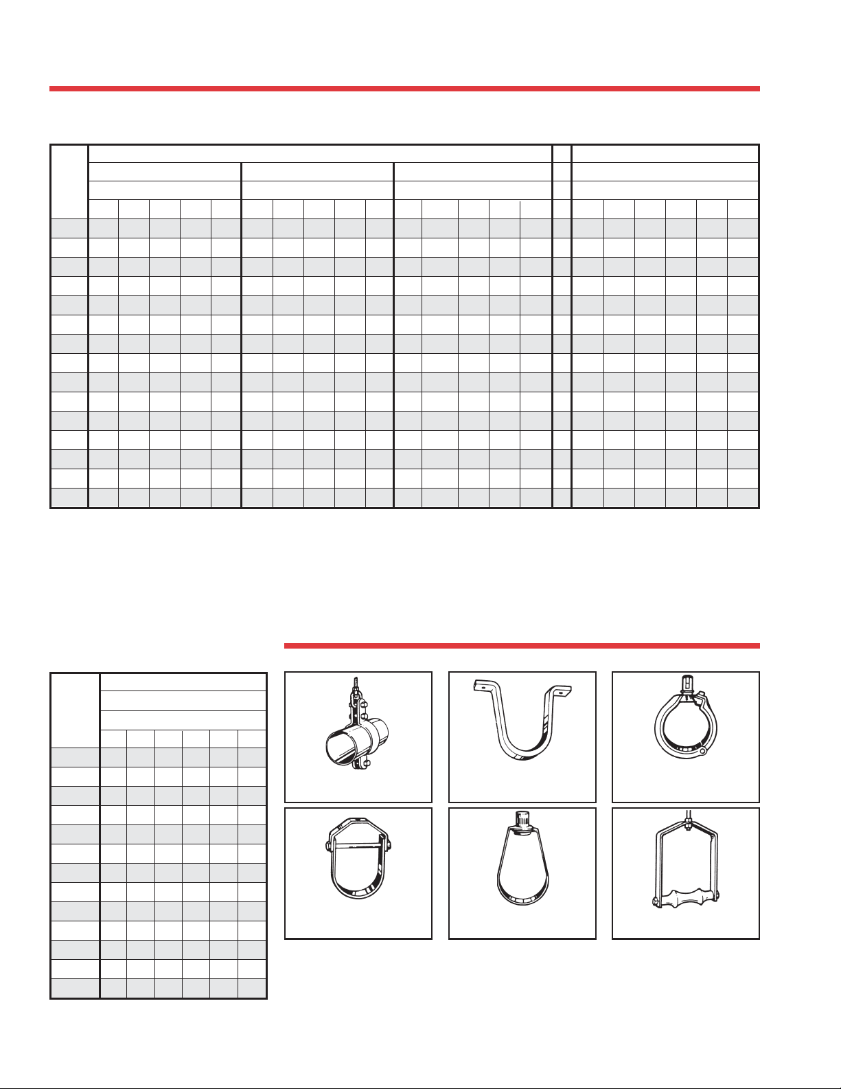
SUPPORT SPACING FOR ABS, PVC
AND CPVC PIPE
Recommended Support Spacing (in feet)
Nom.
Pipe
SDR 21 PR200 & SDR 26 PR160
Size
(in.)
60 8 0 10 0 120 140 60 80 10 0 120 140 60 80 10 0 12 0 14 0 6 0 80 10 0 12 0 14 0 16 0
1
/231/231/232 4
3
4
/
43
1443
11/4443
11/241/24421/
24
21/2554
35
465
66
876
Temp. °F Temp. °F Temp. °F Temp. °F
1
1
/232 54
1
/225
1
2
/221/
2
1
/244 3 651/253
1
/2376
1
/251/241/23 77643
1
/253
1
/261/251/248
1
/265 98
1
2
/
1
51/251/25336 65
65
71/276
1
10 10 9 81/251/2512 1110 7 6
12 111/2101/291/261/251/213 12 101/271/261/
14 12 11 10 7 6 131/213 11 8 7
16 121/2111/2101/271/261/214 131/2111/281/271/
NOTE: Always follow local code requirements for hanger spacing.
PVC PIPE ABS PIPE
Schedule 40 Schedule 80 Schedule 40
/241/242
1
/242
/254
1
/253
1
/2643
/287
1
/2854
1
/221/254
1
/221/251/254
1
/232
1
/2361/265
1
/23761/2643
1
/241/24981/271/254
1
/254
1
/265
1
/271/271/261/241/24
1
/287
1
/210 91/2965 8
1
/211 101/291/261/251/
1
/241/232
1
/232
1
/253
1
/274
1
/23
1
/231/23
1
/231/231/
1
/24 77743
Plastics Technical Manual
1
2
/
1
2
/
2
1
2
/
1
2
/
2
2
2
665
665
71/271/274
1
/281/2854
1
/231/233
1
/231/233
1
2
/231/
1
/244
1
2
/241/
Recommended
Support Spacing
(in feet)
Nom.
Pipe
Size
(in.)
1
2
/
3
4
/
16665
11/461/261/2665
2
11/
27776
2
21/
38887
49998
61010
8111110
10 111/2111/211 101/291/26
12 121/2121/2121/211 101/261/
CPVC PIPE
Schedule 80
Temp. °F
1
/221/
1
/23
1
/231/
180
60 80 100 120 140
51/251/254
1
/241/221/
51/251/251/254
1
/253
7761/265
1
/263
1
87
/271/271/261/24
1
/274
1
/271/241/
1
/291/2985
1
/210 9 51/
Typical Pipe Hangers,
Clamps, and Supports
2
2
2
1
2
/
2
2
Double Bolt Pipe Clamp
3
/4 to 36 in. pipe
Clevis Hanger
1
/2 to 30 in. pipe
Anchor Strap
1
/2 to 4 in. pipe
Adj. Swivel Ring
1
/2 to 8 in. pipe
The pipe should not be anchored tightly by the support, but secured in a manner to
allow for movement caused by thermal expansion and contraction. It is recommended
that you use clamps or straps that allow pipe to remain away from the framing, thus
2
reducing the noise generated when pipe is allowed to rub against wood.
Split Ring Hanger
Adj. Swivel Ring
3
/4 to 8 in. pipe
Roller Hanger
21/2 to 20 in. pipe
42
Page 43
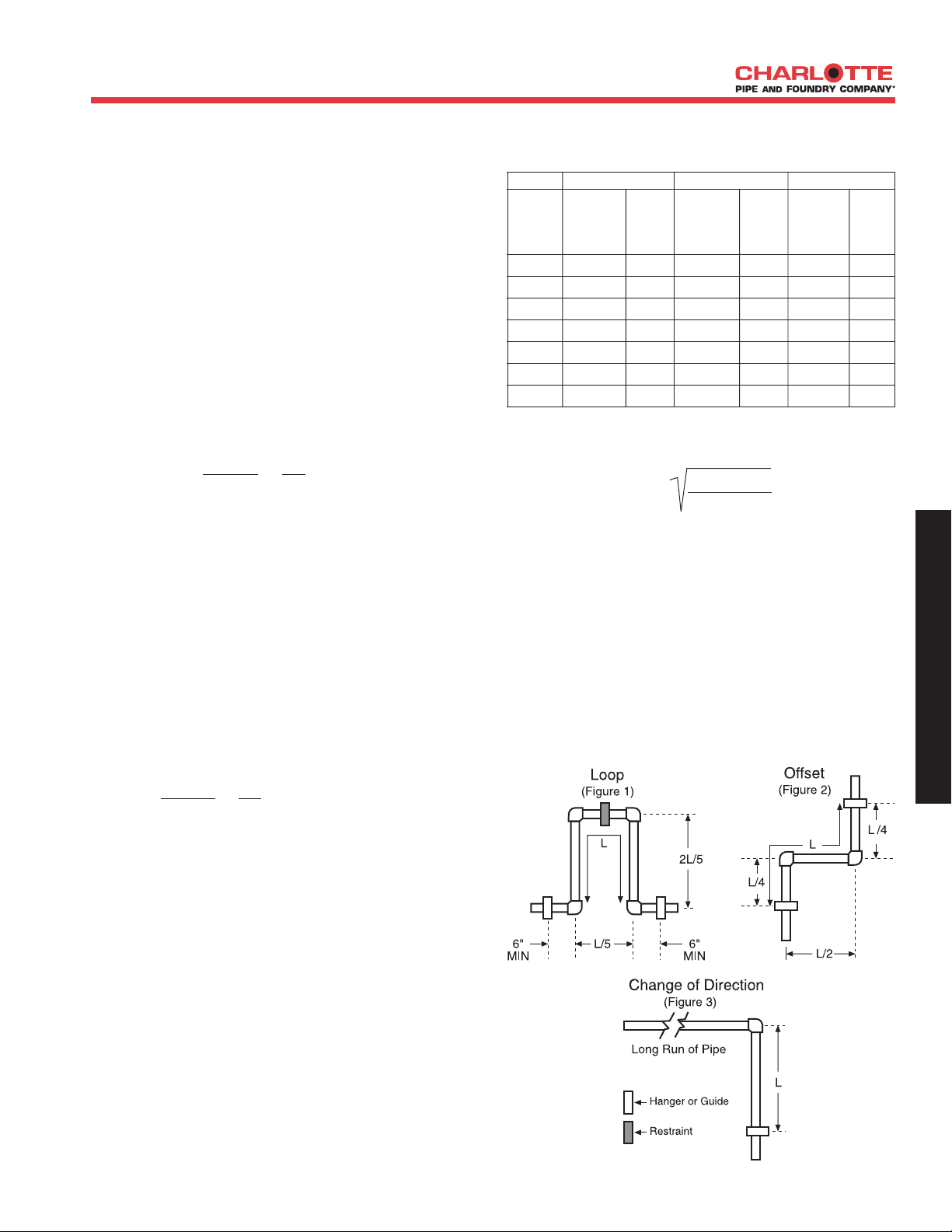
EXPANSION AND CONTRACTION
OF ABS, PVC, AND CPVC
ABS, PVC and CPVC pipe, like other piping materials, undergo
length changes as a result of temperature variations above
and below the installation temperature. They expand and
contract 4.5 to 5 times more than steel or iron pipe. The extent
of the expansion or contraction is dependent upon the piping
material’s coefficient of linear expansion, the length of pipe
between directional changes, and the temperature differential.
The coefficients of linear expansion (Y) for ABS, PVC, and
CPVC (expressed in inches of expansion per 10°F temperature
change per 100 feet of pipe) are as follows:
Material Y (in./10°F/100 ft)
ABS 0.66
PVC 0.36
CPVC 0.408
The amount of expansion or contraction can be calculated
using the following formula:
e = Y (T
1-T2) x Lp h
10 100
e = Dimensional change due to thermal expansion
or contraction (in.)
Y = Expansion coefficient (See table above.)
(in./10°F/100 ft)
(T1-T2) = Temperature differential between the
installation temperature and the maximum or
minimum system temperature, whichever
provides the greatest differential (°F).
Lp = Length of pipe run between changes in
direction (ft)
Example: How much expansion (e) can be expected in a
60 foot straight run of 2" diameter PVC pipe installed at
70°F and operating at 120°F?
Solution:
e = .360 (120 - 70) x 60 =.360 x 5 x .6 = 1.08 inches
10 100
There are several ways to compensate for expansion and
contraction. The most common methods are:
1. Expansion Loops (Fig. 1)
2. Offsets (Fig. 2)
3. Change in direction (Fig. 3)
4. Piston type expansion joints* (Fig. 4)
5. Bellows and/or rubber expansion joints*
6. Flexible Bends*
*The manufacturers of these devices should be contacted to
determine the suitability of their products for the specific
application.
When installing the expansion loop, no rigid or restraining
supports should be placed within the leg lengths of the loop. The
loop should be installed as closely as possible to the mid-point
between anchors. Piping support guides should restrict lateral
movement and direct axial movement into the loop. Lastly, the
pipe and fittings should be solvent cemented together, rather
than using threaded connections.
Modulus of Elasticity & Working Stress
Table 1
ABS PVC CPVC
Modulus of Working Modulus of Working Modulus of Working
Elasticity Stress Elasticity Stress Elasticity Stress
(psi) (psi) (psi) (psi) (psi) (psi)
73° F 250,000 N/A 420,000 2,000 370,000 2,000
90° F 240,000 N/A 380,000 1,500 360,000 1,820
100° F 230,000 N/A 350,000 1,240 350,000 1,640
120° F 215,000 N/A 300,000 800 340,000 1,300
140° F 195,000 N/A 2000,000 400 325,000 1,000
160° F 180,000 N/A N/A N/A 310,000 800
180° F N/A N/A N/A N/A 290,000 500
Modulus Data is Modulus of Elasticiy in Tension per ASTM D 638
Expansion Loop Formula
L = 3 ED (ΔL)
2S
Where:
L = Loop length (in.)
E = Modulus of elasticity at maximum
temerature (psi) (Table 1)
S = Working Stress at maximum
temperature (psi) (Table 1)
D = Outside diameter of pipe (in.) (pages 20-30)
ΔL = Change in length due to change in
temperature (in.)
D
E
S
I
G
N
&
E
N
G
I
N
E
E
R
I
N
G
D
A
T
A
43
Page 44
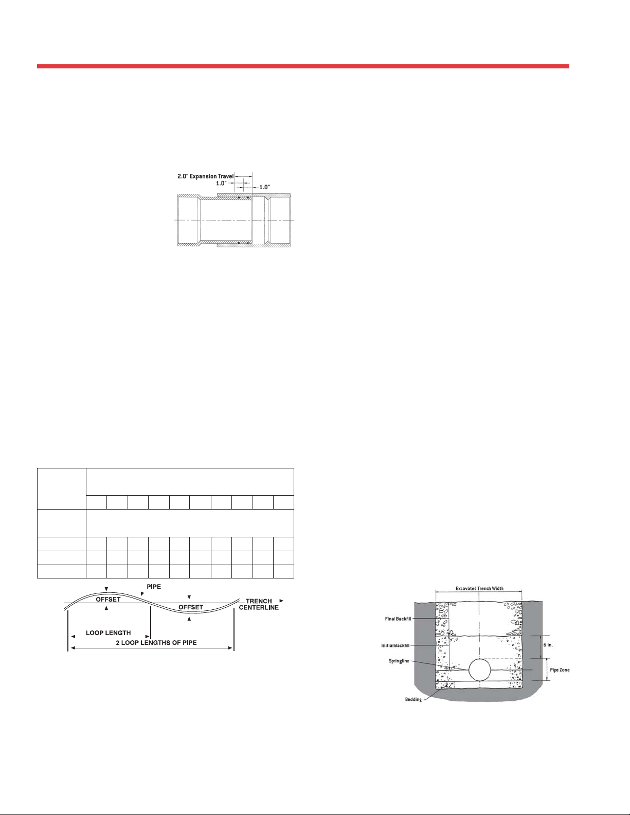
UNDERGROUND INSTALLATION
Plastics Technical Manual
Thermal Expansion in DWV
Systems
Secure above-ground vertical DWV or storm-drainage piping at
sufficiently close intervals to maintain proper alignment and to support
the weight of the piping and its
contents. Support stack at base,
and if over two stories in height,
support stack at base and at each
floor with approved riser clamps.
Stacks should be anchored so
that movement is directed to the
offset or expansion joint. For
verticle stacks in multi-story
applications, compensation for
expansion, contraction or
building settling is recommended. This can be accomplished by
installing a horizontal offset (Fig. 2) or expansion joint (Fig. 4) at a
minimum of every other floor. Expansion joints should be installed in
the neutral position. Compensation for thermal movements is usually
not required for a vent system.
Piston Type Expansion Joint Illustrated
(Charlotte Pipe Part No. PVC 133)
Figure 4
3. The trench bottom should be smooth, free of rocks and debris,
4. Trench depth is determined by the pipe’s service requirements.
5. A smooth, trench bottom is necessary to support the pipe over
Thermal Expansion in
Underground Systems
A. Joining the pipe in the trench.
B. Snaking the pipe from side to side to compensate for
expansion and contraction.
C. Filling and compacting the side fills.
The space between the pipe and trench wall must be wider than
the compaction equipment used in the compaction of the backfill.
Minimum width shall be not less than the greater of either the
pipe outside diameter plus 16 inches or the pipe outside diameter
times 1.25 plus 12 inches. Trench width may be different if
approved by the design engineer.
continuous, and provide uniform support. If ledge rock, hardpan
or large boulders are encountered, the trench bottom should
be padded with bedding of compacted aggregate material to a
thickness of at least 4 inches. Foundation bedding should be
installed as required by the engineer.
Plastic pipe should always be installed at least below the frost
level. The minimum cover for lines subject to heavy overhead
traffic is 24 inches.
its entire length on firm stable material. Blocking should not be
used to change pipe grade or to intermittently support pipe over
low sections in the trench.
Compensation for expansion and contraction in underground
applications is normally achieved by snaking the pipe in the trench.
Solvent cemented joints must be used.
The following table shows recommended offsets and loop lengths for
piping up to 2 1/2" nominal size.
Max. Temp. Variation °F, Between Installation
and Final Operation
10°20°30°40°50°60°70°80°90°100
Loop Length
In Feet
20 3.0 3.5 4.5 5.0 6.0 6.5 7.0 7.0 8.0 8.0
50 7.0 9.0 11.0 13.0 14.0 15.5 17.0 18.0 19.0 20.0
100 13.0 18.0 22.0 26.0 29.0 31.5 35.0 37.0 40.0 42.0
Loop Offset In Inches
Bedding and Backfilling
1. Even though sub-soil conditions vary widely from place to place,
2. The pipe should be surrounded with an aggregate material which
°
3. A mechanical tamper is recommended for compacting sand and
4. The trench should be completely filled. The backfill should be
Trenching
The following trenching and burial procedures should be used to
protect the piping system.
1 . The trench should be excavated to ensure the sides will be stable
under all working conditions.
2. The trench should be wide enough to provide adequate room for
the following.
44
Additional information is contained in ASTM D 2321 “Underground
Installation of Thermoplastic pipe for Sewers and Other GravityFlow Applications” (non-pressure applications) and in ASTM F 1668
"Construction Procedures for Buried Plastic Pipe."
the pipe backfill should be stable and provide protection for the
pipe.
is easily worked around the sides of the pipe. Backfilling should
be performed in layers of 6 inch with each layer being sufficiently
compacted to 85% to 95% compaction.
gravel backfill which contain a significant proportion of fine
grained material, such as silt and clay. If a tamper is not
available, compacting should be done by hand.
placed and spread in fairly uniform layers to prevent any unfilled
spaces or
voids.
Large
rocks,
stones,
frozen
clods, or
other large
debris
should be
removed.
Heavy tampers or rolling equipment should only be used to
consolidate only the final backfill.
Page 45
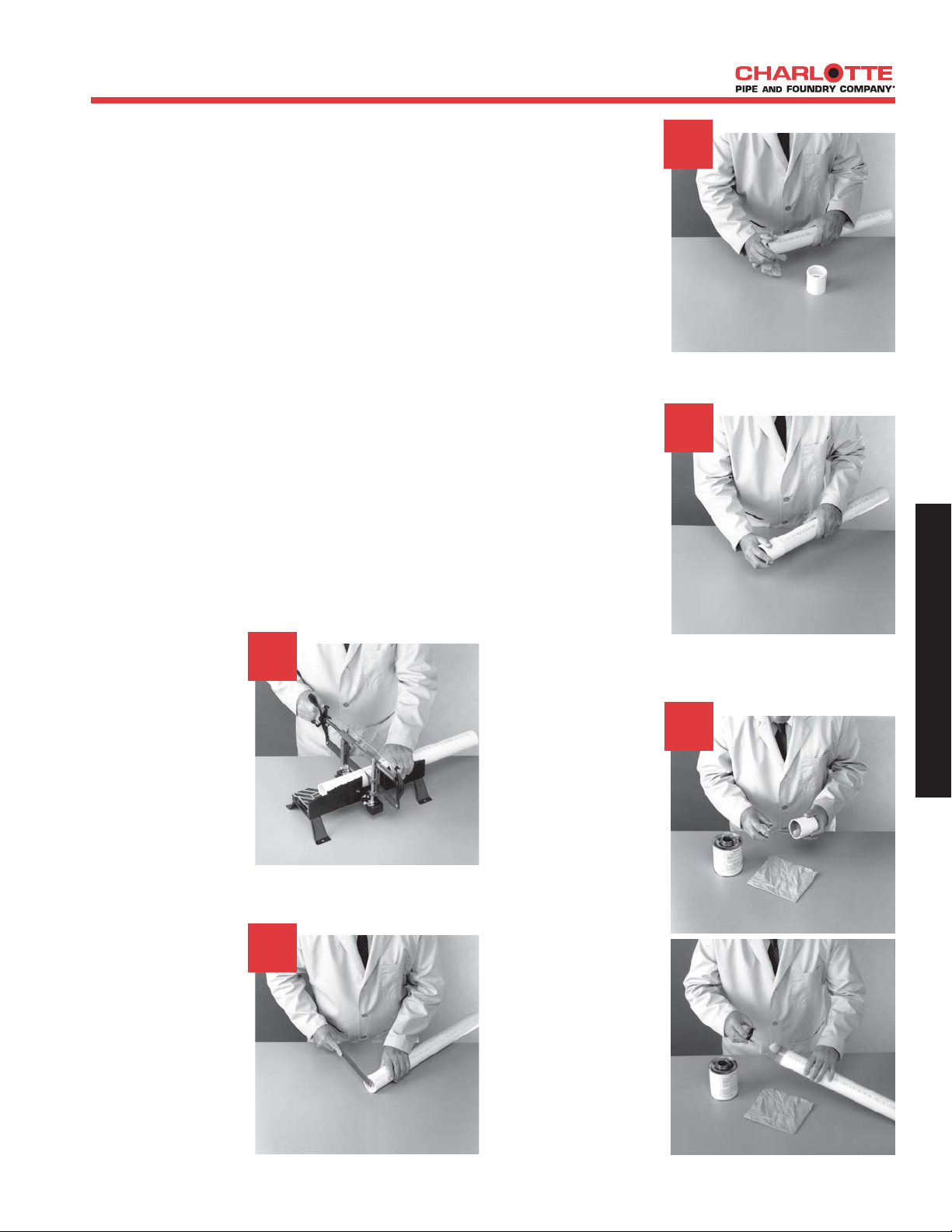
INSTALLATION PROCEDURES
Installation Procedures for
ABS, PVC and CPVC Piping
Systems
With our reliable, easy-to-install ABS, PVC and CPVC TrueFit
systems, Charlotte Pipe and Foundry is doing more than any
other supplier to help contractors work more efficiently and
productively.
The following information contains suggested installation and
testing procedures and does not encompass all of the
requirements for the design or installation of a piping system.
• Observe all safety precautions.
• Systems should be installed in a good and workmanlike
manner consistent with normal industry standards and in
conformance with all local plumbing, fire and building
code requirements. Failure to follow proper installation
practices, procedures, or techniques can result in system
failure, property damage, or personal injury.
• Pipe and fitting systems should be used for their intended
purpose as defined by local plumbing and building codes
and the applicable ASTM standard.
• Follow manufacturers' instructions for all related products.
1. Cut Pipe
• Cut pipe square.
As joints are sealed
at the base of the
fitting hub. An
angled cut may
result in joint
failure.
• Acceptable tools
include miter saw,
mechanical cut off
saw or wheel
cutter. Wheel type cutters must employ a blade designed
for plastics.
2. Remove Burr And
Bevel
• Remove all pipe
burr from inside
and outside diameter of pipe with
a knife-edge, file,
or deburring tool.
1
2
3. Clean and Dry
Pipe and Fittings
• Remove surface
dirt, grease, or
moisture with a
clean dry cloth.
4. Dry Fit
•
With light
pressure
should go one half
to one third of the
way into the fitting
hub. Pipe and
fittings that are too
tight or too loose
should not be used.
5. Applicator
• Use an applicator
that is one half the
pipe diameter.
• Too large an applicator will force
excessive cement
into the inside of
small diameter
fittings. Too small
an applicator will
not apply sufficient
cement to large
diameter systems.
, pipe
3
4
5
D
E
S
I
G
N
&
E
N
G
I
N
E
E
R
I
N
G
D
A
T
A
• Chamfer (bevel)
the end of the pipe
10° -15° as shown
to the right.
45
Page 46
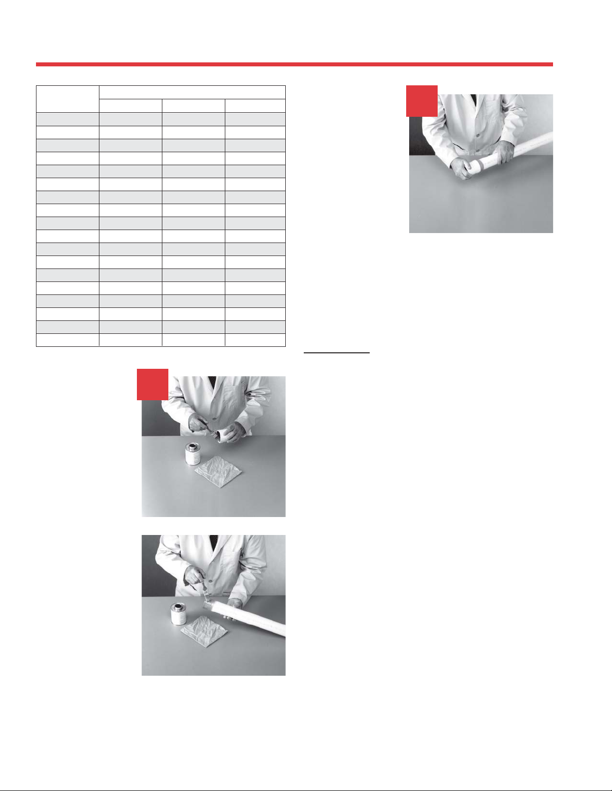
INSTALLATION PROCEDURES
Plastics Technical Manual
Nominal Pipe
Size (in.)
1
/4 A
3
/8 A
1
/2 A
3
/4 A1NR
1A1NR
11/4 A1NR
11/2 A 1 - 11/2 NR
2 A 1 - 11/2 NR
21/2 NR 11/2 - 2 NR
3NR1
4NR2 - 33
5NR3 - 53
6NR3 - 53
8NR4 - 67
10 NR 6 - 8 7
12 NR 6 - 8 7
14 NR 7 - 8 7
16 NR 8+ 8
A = Acceptable NR = Not Recommended
6. Coat Surfaces
with Primer and
Cement
Dauber Brush Width (in.)
Applicator Type
1
/2 - 21/2 NR
6
1
/2 NR
1
/2 NR
1
/2 NR
Roller Length (in.)
7. Join Pipe and
Fittings
• Assemble pipe and
fittings quickly
while cement is
fluid.
• Insert pipe into
fitting hub until it
contacts socket
bottom. Give pipe
a quarter turn.
Hold pipe and
fitting together until the pipe does not back out.
• See table for recommended cure times.
• Remove excessive cement from the exterior. A properly
made joint will show a continuous bead of cement around
the perimeter.
Threaded Joint
When combining plastic and metal threaded systems, it is
recommended that plastic male threads be screwed into metal
female threads rather than metal male threads into plastic
female threads.
7
• Apply primer to
PVC and CPVC
pipe and fitting
surfaces. Do not
allow primer to
puddle inside the
system. Primer
should conform to
ASTM F 656.The
use of primer for
ABS is not
recommended.
• Apply a full even
layer of cement on
the pipe O.D. for a
distance slightly
greater than the
depth of the socket
of the fitting.
• Coat the fitting
socket with a
medium layer of cement, avoiding puddling inside the
system. Apply a second full even layer of cement on the
pipe O.D. Solvent cement should meet ASTM D 2564 for
PVC systems, ASTM F 493 for CPVC systems, and ASTM
D 2235 for ABS systems.
46
Page 47
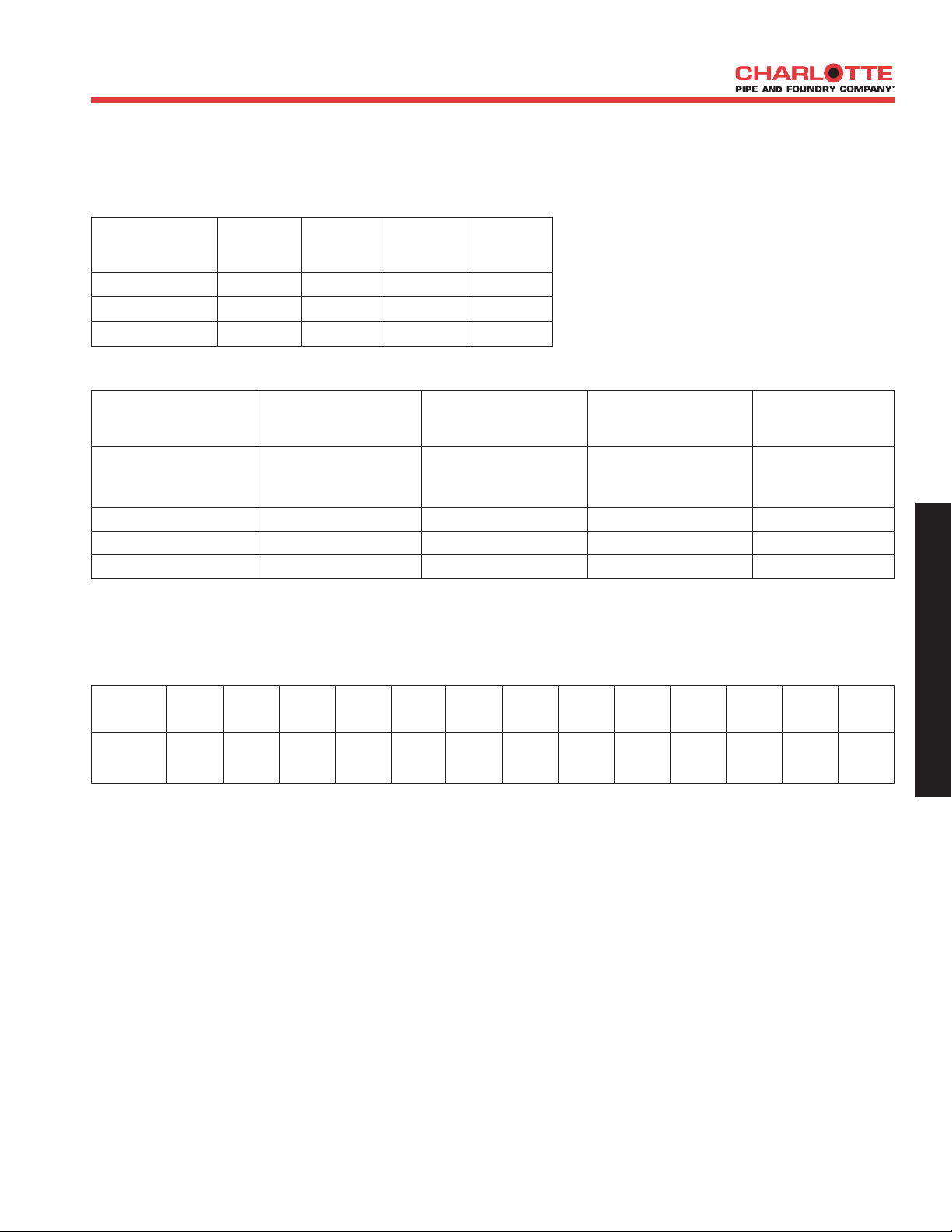
JOINT CURING
Joint Curing
The joint should not be disturbed until it has initially set. The chart below shows the recommended initial set times.
Recommended Initial Set Times
Temperature Pipe Sizes Pipe Sizes Pipe Sizes Pipe Sizes
1
Range
/2" to 11/4"11/2" to 3"4" to 8"10" to 16
60° - 100° F 15 min 30 min 1 hr 2 hr
40° - 60° F 1 hr 2 hr 4 hr 8 hr
The joint should not be pressure tested until it has
"
cured. The exact curing time varies with
temperature, humidity, and pipe size. The following
chart shows suggested curing times.
0° - 40° F 3 hr 6 hr 12 hr 24 hr
Recommended Curing Time Before Pressure Testing
RELATIVE HUMIDITY CURE TIME CURE TIME CURE TIME CURE TIME
60% or Less* Pipe Sizes 1/2"
to 11/4"
Pipe Sizes 11/2"
to 3
"
Pipe Sizes 4" to 8
"
Pipe Sizes 10" to 16
Temperature Range
During Assembly and Up to Above 180 Up to Above 180 Up to Above 180 Up to
Cure Periods 180 psi to 370 psi 180 psi to 315 psi 180 psi to 315 psi 100 psi
60° - 100° F 1 hr 6 hr 2 hr 12 hr 6 hr 24 hr 24 hr
40° - 60° F 2 hr 12 hr 4 hr 24 hr 12 hr 48 hr 48 hr
0° - 40° F 8 hr 48 hr 16 hr 96 hr 48 hr 8 days 8 days
*For relative humidity above 60%, allow 50% more cure time.
The above data are based on laboratory tests and are intended as guidelines.
For more specific information, contact should be made with the cement manufacturer.
*Average number of joints per Quart for Cement and Primer (Source: IPS Weld-on)
Pipe
Diameter 1/2
"
3/4
"
1
"
1-1/2
"
2
"
3
"
4
"
6
"
8
"
10
"
12
"
15
"
Number
of Joints 300 200 125 90 60 40 30 10 5 2 to 3 1 to 2 3/4 1/2
For Primer: double the number of joints shown for cement.
* These figures are estimates based on IPS Weld-on laboratory tests.
Due to many variables in the field, these figures should be used as a general guide only.
18
"
D
E
S
I
G
N
&
E
N
G
I
N
E
E
R
I
"
N
G
D
A
T
A
Testing Pressure System
1. Prior to testing, safety precautions should be instituted
to protect personnel and property in case of test failure.
2. Conduct pressure testing with water. DO NOT USE AIR
OR OTHER GASES for pressure testing.
3. The piping system should be adequately anchored to limit
movement. Water under pressure exerts thrust forces in
piping systems. Thrust blocking should be provided at
changes of direction, change in size and at dead ends.
4. The piping system should be slowly filled with water, taking
care to prevent surge and air entrapment. The flow velocity
should not exceed 5 feet per second (see charts on pages
37-41).
5. All trapped air must be slowly released. Vents must be
provided at all high points of the piping system. All valves
and air relief mechanisms should be opened so that the
air can be vented while the system is being filled. Trapped
air is extremely dangerous and it must be slowly and
completely vented prior to testing.
6. Once an installation is completed and cured the system
should be filled with water and pressure tested in
accordance with local code requirements. However, care
must be taken to ensure the pressure does not exceed the
working pressure of the lowest component in the system
(valves, unions, flanges, threaded parts, etc.)
7. The pressure test should not exceed one hour. Any leaking
joints or pipe must be cut out and replaced and the line
recharged and retested using the same procedure.
47
Page 48
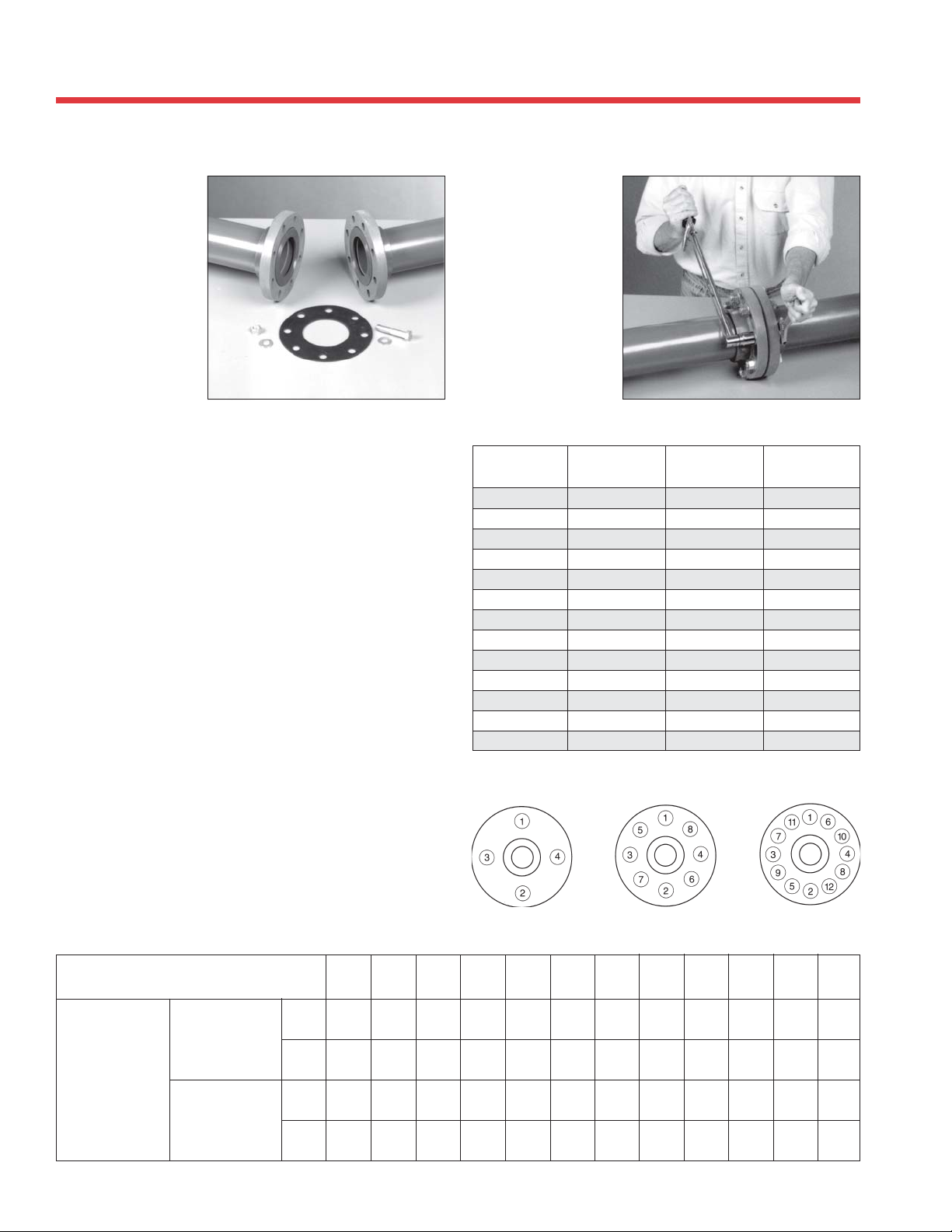
FLANGES AND UNIONS
PVC AND CPVC PIPE
For systems where dismantling is required, flanging is a
convenient joining method. It is also an easy way to join plastic
and metallic systems.
Installation
1. Join the flange to the pipe using the procedures shown in
the solvent cementing or threading sections.
2. Use a full faced elastomeric gasket which is resistant to
the chemicals being conveyed in the piping system. A
gasket 1/8" thick with a Durometer, scale “A”, hardness
of 55 -80 is normally satisfactory.
3. Align the flanges and gasket by inserting all of the bolts
through the mating flange bolt holes. Be sure to use
properly sized flat washers under all bolt heads and nuts.
4. Sequentially tighten the bolts corresponding to the
patterns shown below.
Plastics Technical Manual
5. Use a torque wrench to tighten the bolts to the torque
values shown below.
Recommended Torque
Pipe Size
In Inches
1
/2 4
3
/4 4
141/2 10 - 15
11/4 4
11/2 4
245/8 20 - 30
21/2 4
345/8 20 - 30
485/8 20 - 30
683/4 33 - 50
883/4 33 - 50
10 12
12 12
No. Bolt
Holes
Bolt
Diameter
1
/2 10 - 15
1
/2 10 - 15
1
/2 10 - 15
1
/2 10 - 15
5
/8 20 - 30
7
/8 53 - 75
7
/8 53 - 75
Recommended
Torque ft/lbs
Note: Flanges meet the bolt-pattern requirements of ANSI / ASME B 16.5
FLANGE BOLT TIGHTENING SEQUENCE
Pressure Rating of PVC and CPVC Unions and Flanges at Elevated Temperatures
System Operating Temp. 100 110 120 130 140 150 160 170 180 190 200 210
Temperature °F (C) (38) (43) (49) (54) (60) (66) (71) (77) (82) (88) (93) (99)
235 211 150 75 50 0 0 0 0 0 0 0
(1.62) (1.45) (1.03) (.52) (.34) (0) (0) (0) (0) (0) (0) (0)
235 219 170 145 130 110 90 80 70 60 50 0
(1.62) (1.51) (1.17) (1.00) (.90) (.76) (.62) (.55) (.48) (.41) (.34) (0)
150 135 110 75 50 0 0 0 0 0 0 0
(1.03) (.93) (.76) (.52) (.34) (0) (0) (0) (0) (0) (0) (0)
150 140 130 120 110 100 90 80 70 60 50 0
(1.03) (.97) (.90) (.83) (.75) (.70) (.62) (.55) (.48) (.41) (.34) (0)
48
Pressure
Rating
psi (Mpa)
1/2" - 2
2-1/2" - 6
PVC
"
CPVC
PVC
"
CPVC
Page 49
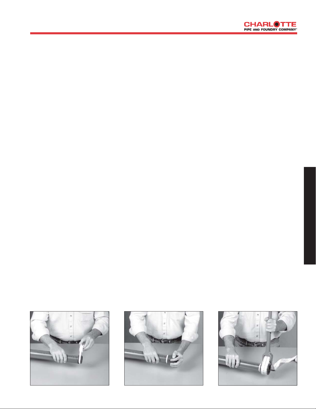
THREADED JOINTS AND THREADING OF
PVC AND CPVC PIPE
Charlotte Pipe generally recommends socket (solvent cement)
jointing for thermoplastic piping systems. Threaded systems
may be used for smaller-size, low-pressure plastic systems, if
desired. Transitions to metal or other dissimilar materials may
be completed using molded male or female threaded adapters
or cut threads on Schedule 80 pipe or flanges.
Only Schedule 80 PVC or CPVC pipe can be threaded. Schedule
40 or SDR pipe cannot be threaded; molded threaded adapters
must be used on those systems. The pressure rating of molded
or cut threads must be derated by 50%.
See pressure/temperature derating information in this technical
manual for systems exposed to operating conditions above 73°F.
Procedure for Cutting Threads
in Schedule 80 Pipe:
1. Cutting
The pipe must be cut square using a power saw, a miter box,
or a plastic pipe cutter. Burrs should be removed using a knife
or deburring tool.
2. Threading
Threads can be cut using either hand held or power threading
equipment. The cutting dies should be clean, sharp, and in
good condition. Special dies for cutting plastic pipe are
available and are recommended.
When using a hand threader, the dies should have a 5° to 10°
negative front rake. When using a power threader, the dies
should have a 5° negative front rake and the die heads should
be self-opening. A slight chamfer to lead the dies will speed
production. However, the dies should not be driven at high
speeds or with heavy pressure.
When using a hand held threader, the pipe should be held in a
pipe vise. To prevent crushing or scoring of the pipe, a
protective wrap such as emery paper, canvas, rubber, or a
light metal sleeve should be used.
Insert a tapered plug into the end of the pipe to be threaded.
This plug will provide additional support and prevent distortion
of the pipe in the threading area.
It is recommended that a cutting lubricant, such as a soap
and water solution or a water soluble machine oil, be used
during the threading operation. Also, clearing the cuttings
from the die is highly recommended.
Do not over-thread the pipe. Consult the diagram and table
showing ASTM F 1498 dimensions for American Standard
Taper pipe threads. Periodically check the threads with a ring
gauge to ensure that the threads are accurate. The tolerance
is ± 11/2 turns.
Installation of Threaded
Connections:
Make sure the threads are clean. Charlotte Pipe generally
recommends Teflon* tape as a sealant for threaded
connections. Use a good quality Teflon tape which has .4
minimum density, .003" thick, .50% elongation and chemically
inert. Wrap the Teflon tape around the entire length of the
threads; start with two wraps at the end and wrap all threads
overlapping half the width of the tape. Wrap in the direction
of the threads on each wind.
Charlotte does not recommend pipe joint compounds, pastes
or lubricants for thermoplastic pipe as the use of an
incompatible compound may result in the degradation or failure
of the plastic pipe or fittings. If using one of these compounds
as a thread sealant, always verify with the manufacturer of
those compounds the suitability for use with ABS, PVC or
CPVC. Charlotte Pipe cannot be responsible for any failures
associated with the use of incompatible thread sealants or
joint compounds.
Make threaded connections and hand tighten. Further tighten
approximately one turn past hand tight using a strap wrench
only. Do not use common wrenches or tools designed for
metallic pipe systems. Avoid over-tightening as this will cause
distortion or damage to threads or fittings.
*Trademark of the E.I. DuPont Company
D
E
S
I
G
N
&
E
N
G
I
N
E
E
R
I
N
G
D
A
T
A
49
Page 50
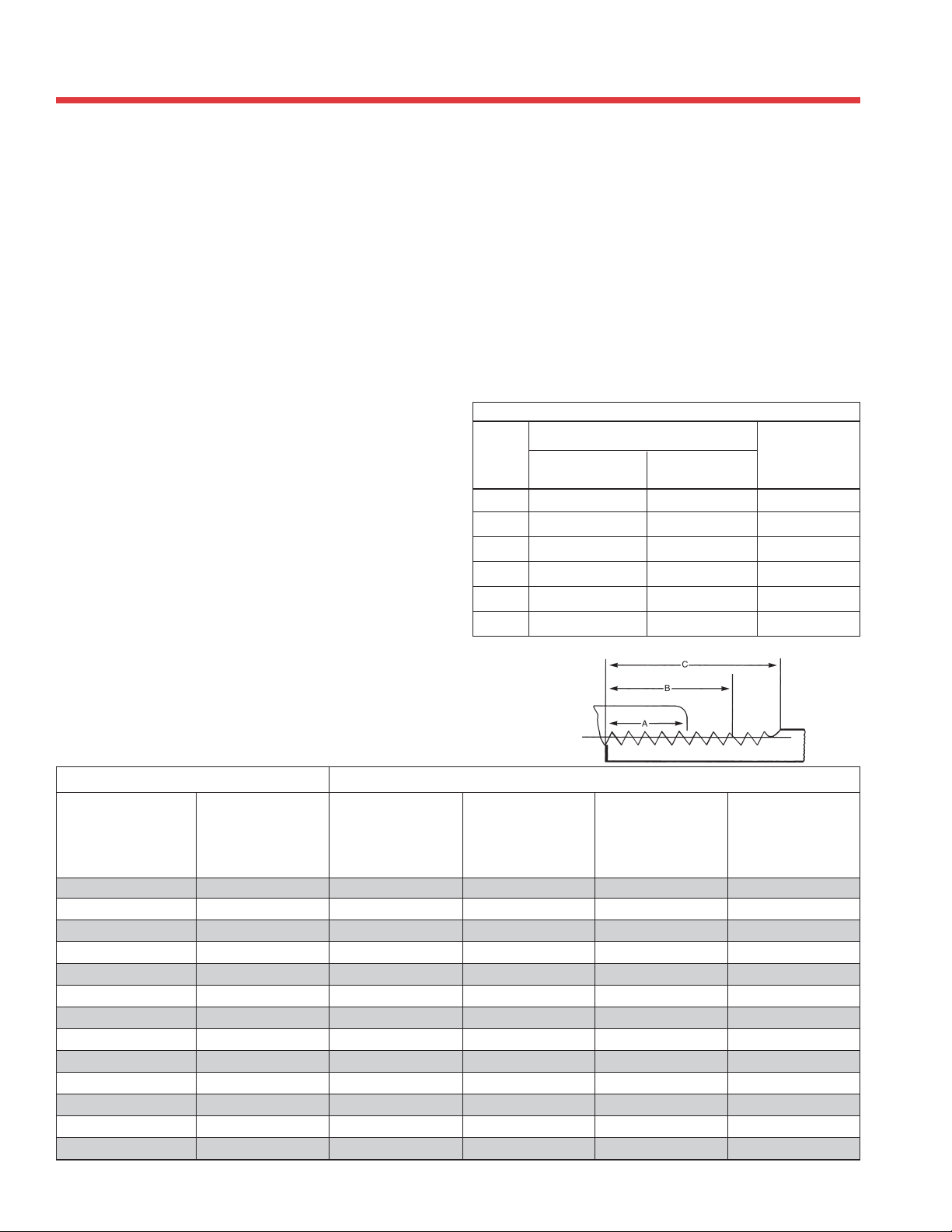
THREADED JOINTS AND THREADING OF
PVC AND CPVC PIPE
Notes on Threaded Connections:
• Make threaded connections on FlowGuard Gold® CPVC
systems using Charlotte® brass transition fittings. See the
Charlotte FlowGuard Gold® Technical Manual for more
information. These fittings are available in male, female
and drop-ear ell configurations.
• When connecting to metallic piping components the
preferred connection method is to use plastic male threads
screwed into female metallic pipe threads. Metallic male
pipe threads exert high stress levels on female plastic pipe
threaded fittings and should be avoided wherever possible.
• Only join to threaded components conforming to ANSI/
ASME B 1.20.1 or ASTM F 1498.
• Brass threaded transition fittings are recommended for
all hot water applications.
• Teflon tape is recommended for all threaded connections
and should be a .4 minimum density, .003” thick, .50%
elongation and chemically inert. To apply start with two
wraps at fitting end, wrap all threads overlapping half
the width of the tape in the direction of the threads on
each wind.
Use of improper paste type pipe sealant may result in
failure of pipe or fittings. Always verify with the manu-
Plastics Technical Manual
facturer of the pipe sealant to confirm chemical compatibility with CPVC and brass components. Never
use joint compound containing ammonia or chlorine
on brass threaded fittings.
Note:
• Never use pneumatic tools for tightening.
• Never apply more than light pressure on male
brass or CPVC threaded fitting when clamping in
a vise.
• Never clamp female brass transition fittings in a
vise.
The following chart shows the correct amount of tape and
torque required to make a properly functioning assembly.
Installation of Brass and CPVC Threaded Fittings
Torque Setting
Pipe Brass Threaded CPVC Threaded Teflon
Size Fittings Fittings Tape
1/2
"
3/4
"
1
"
1 1/4"30 to 60 ft.lbs. 5 to 7 ft.lbs 1" width
1 1/2"23 to 34 ft.lbs. 6 to 8 ft.lbs 1" width
2
"
14 ft.lbs. 3 to 5 ft.lbs. 1/2" width
18 ft.lbs. 4 to 6 ft.lbs. 1/2" width
24 ft.lbs. 5 to 7 ft.lbs 1/2" width
36 to 50 ft.lbs. 8 to 10 ft.lbs 1" width
Note: 1 foot pound = 12 inch pounds
External Taper Thread Dimensions Diagram
*Per ANSI/AME B1.20.1 and ASTM F 1498
Nominal
Size
In Inches
1
/4 .540 18 .228 .4018 .5946
3
/8 .675 18 .240 .4078 .6006
1
/2 .840 14 .320 .5337 .7815
3
/4 1.050 14 .339 .5457 .7935
1 1.315 111/2 .400 .6828 .9845
11/4 1.660 111/2 .420 .7068 1.0085
11/2 1.900 111/2 .420 .7235 1.0252
2 2.375 111/2 .436 .7565 1.0582
21/2 2.875 8 .682 1.1375 1.5712
3 3.500 8 .766 1.2000 1.6337
4 4.500 8 .844 1.3000 1.7337
6 6.625 8 .958 1.5125 1.9462
8 8.625 8 1.063 1.7125 2.1462
Outside
Diameter
In Inches
(D)
Number
of Threads
Per Inch
* EXTERNAL THREADPIPE
Normal
Engagement By
Hand In Inches
(A)
Length of
Effective Thread
In Inches
(B)
Total Length: End
of Pipe to Vanish
Point In Inches
(C)
50
Page 51
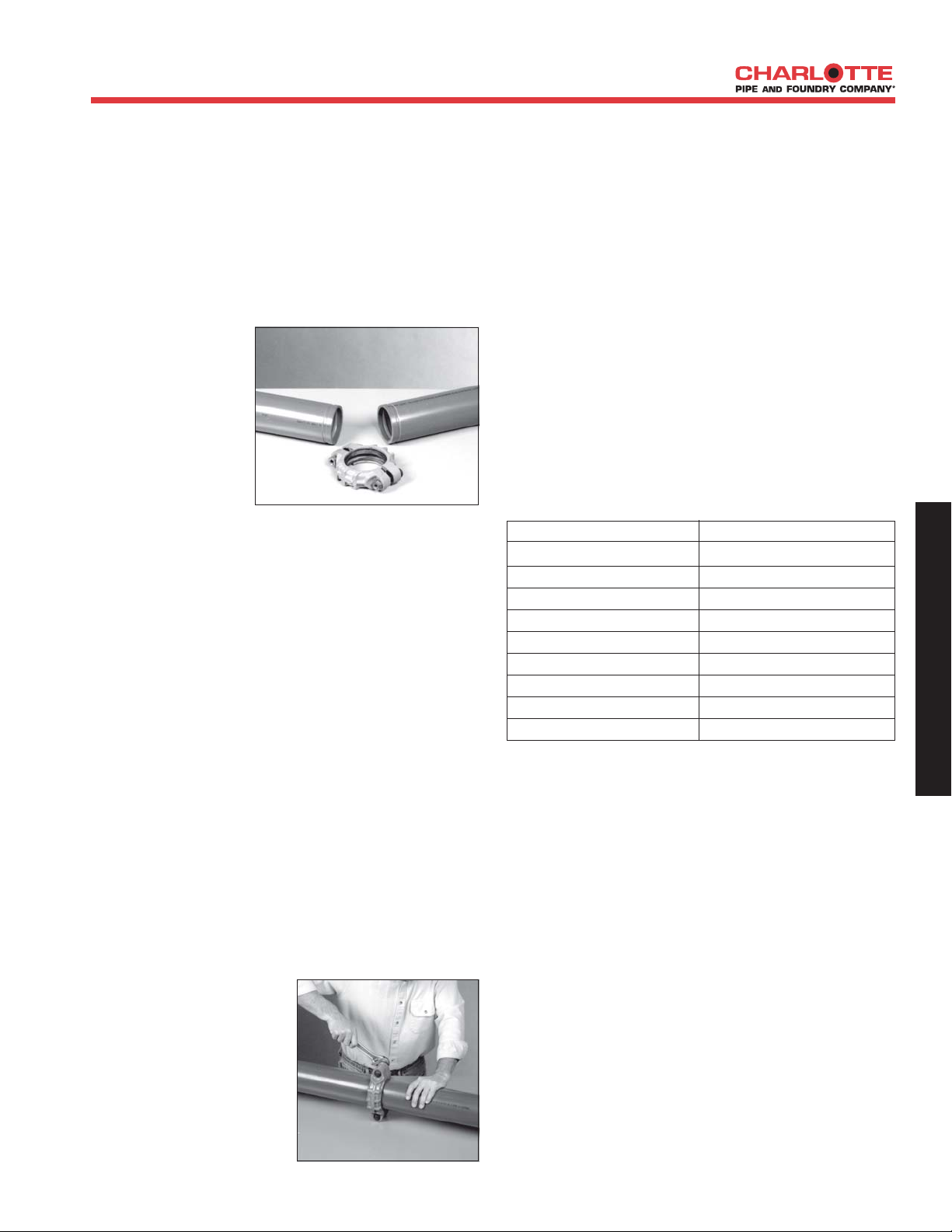
JOINING ROLL-GROOVED PIPE
and ANTIFREEZE SOLUTIONS
Joining Roll-Grooved Pipe
Roll-grooved PVC pipe is designed for use with conventional
gasketed mechanical couplings. It offers a method of joining
which is quick and convenient, and it can be used in
applications where frequent assembly and disassembly are
desirable.
Installation
1. Consult with the
manufacturer of
the couplings for
recommendations
on the coupling
style(s) designed
for use with PVC
pipe and the
gasket material
which is suitable
for the intended service.
2. Check the pipe ends for any damage, roll marks,
projections, or indentations on the outside surface
between the groove and the end of the pipe. This is the
sealing area, and it must be free of any defects.
3. Disassemble the coupling and remove the gasket. Inspect
for any damage and make sure the gasket material is
suitable for the intended service. Apply a thin coat of
silicone lubricant to the gasket tips and the outside of
the gasket.
4. Slide the gasket onto the end of one length of pipe so
that it is flush with the end. Align and bring the end of
another length of pipe together while sliding the gasket
back over this junction. The gasket should be centered
between the grooves and should not extend into the groove
on either length of pipe.
5. Place the coupling housings over the gasket. The housing
keys should engage into the grooves. Insert the bolts and
apply the nuts. Tighten to “finger tight.”
6. Using a wrench,
alternately tighten the
nuts to the coupling
manufacturer’s
specifications. Over
tightening is not
necessary, and uneven
tightening may cause
gasket pinching.
Antifreeze Solutions - Pressure
Testing CPVC and PVC Piping
at Reduced Temperature
Glycerin antifreeze solutions are recommended for use
with FlowGuard Gold® and Corzan® water distribution
systems and for PVC pressure and DWV applications.
Glycerin antifreeze should be diluted to the appropriate
concentration that provides adequate protection for the
intended application. Maximum freeze protection for glycerinwater solutions is -51.7ºF (-46.5ºC) and occurs when the
weight percent of glycerin is 66.7%. The effectiveness of a
glycerin/water antifreeze solution diminishes above this
concentration. Freeze points of glycerin-water solutions follow:
Freezing Points of Glycerin-Water Solutions
(weight %)
Glycerin by weight (%) Freeze Point °F (°C)
0 32.0 (0.0)
10 29.1 (-1.6)
20 23.4 (-4.8)
30 14.9 (-9.5)
40 4.3 (-15.4)
50 -9.4 (-23.0)
60 -30.5 (-34.7)
66.7 -51.7 (-46.5)
Greater than 66.7 Not Recommended
Propylene glycol or ethylene glycol antifreeze solutions
are suitable for use in pressure testing PVC pressure and
DWV piping systems as follows:
• Solutions greater than 50% propylene glycol are
incompatible with PVC and may cause damage to PVC
piping systems.
• Ethylene glycol is compatible with PVC piping systems
up to 100% concentrations.
• 25% Propylene glycol solutions are approved for use with
potable water systems and provide freeze protection to
about 15ºF(-10ºC), 50% solutions provide freeze
protection to -30ºF (-34ºC ).
• Ethylene glycol solutions are toxic and must therefore
be avoided in potable water and food processing
systems. 25% ethylene glycol solutions provide freeze
protection to about 8ºF (-13ºC) and 50% solutions
provide freeze protection to about - 33ºF (-36ºC).
D
E
S
I
G
N
&
E
N
G
I
N
E
E
R
I
N
G
D
A
T
A
51
Page 52

TESTING AND INSPECTION
Plastics Technical Manual
Once the roughing-in is completed on a plastic drain,
waste, and vent piping system, it is important to test and
inspect all piping for leaks. Concealed work should remain
uncovered until the required test is made and approved.
When testing, the system should be properly restrained at
all bends, changes of direction, and the end of runs.
There are various types of procedures used for testing
installed plastic systems. CAUTION: In any test, proper
safety procedures and protective eyewear, clothing,
and equipment should be used. Installers should
always consider local conditions, codes and
regulations, manufacturer’s installation instructions,
and architects’/engineers’ specifications in any
installation.
Testing DWV System
Water Test
A water or hydrostatic test is the most technically superior
test used to inspect a completed plastic piping system
installation and is the testing procedure recommended by
Charlotte Pipe. It is also the most recommended test in
most plumbing code standards. The purpose of the test is to
locate any leaks at the joints and correct them prior to
putting the system into operation. Since it is important to
be able to visually inspect the joints, a water test should be
conducted prior to closing in the piping or backfilling of
underground piping.
Once the stack is filled to “ten feet of head,” a visual
inspection of the section being tested should be made to check
for leaks. If a leak is found, the joint must be cut out and a
new section installed. Fifteen minutes is a suitable time for
the water test. Once the system has been successfully tested, it
should be drained and the next section prepared for testing.
DO NOT USE CHARLOTTE PIPE
PRODUCTS FOR COMPRESSED AIR OR
GASES
Charlotte Pipe and Foundry Company products are not intended
to be used for distribution or storage of compressed air or
gases. Use of Charlotte Pipe products in inappropriate
applications could result in product failure, serious injury or
death.
Air or Gas Testing - Not Recommended
Air or compressed gas test are sometimes performed instead
of hydrostatic (water) test. DANGER: Charlotte Pipe and
Foundry Company does not recommend air or gas testing,
consistent with PPFA User Bulletin 4-80 and / or ASTM D
1785. Pipe and fitting materials under air or gas pressure
can explode, causing serious injury or death. Charlotte
Pipe will not be responsible or liable for injury or death to
persons or damage to property or for claims for labor and /
or material arising from any alleged failure of our products
during testing with air or compressed gasses.
To isolate each floor or section being tested, test plugs are
inserted through test tees in the stack. All other openings
should be plugged or capped with test plugs or test caps.
When testing Foam Core pipe, always use external
caps to eliminate the possibility of leakage through
the foam core part of the pipe. Fill the system to be
tested with water at the highest point. As water fills a
vertical pipe it creates hydrostatic pressure. The pressure
increases as the height of the water in the vertical pipe
increases. Charlotte Pipe recommends testing at 10
feet of hydrostatic pressure (4.3 pounds per square
inch.) Filling the system slowly should allow any air in the
system to escape as the water rises in the vertical pipe. All
entrapped air in the system should be expelled prior to
the beginning of the test. Failure to remove entrapped
air may give faulty test results.
52
Page 53
HYDRONIC HEATING APPLICATIONS
Hydronic Heating Applications
The table below highlights key points to remember when installing FlowGuard Gold or Corzan CPVC in a hydronic
radiant heating application. A hydronic radiant heating application is defined here as piping directly off a hot
water heater or boiler into a coil heating unit in single- or multi-family homes.
“DOs” for all hydronic applications
• Install in accordance with both Charlotte Pipe and
Foundry’s and solvent cement manufacturer’s
recommendations and installation instructions.
• Follow recommended safe work practices.
• Verify that the maximum outlet temperature and
pressure of the boiler is less than the temperature
and pressure rating of the pipe (see charts below).
• Always use the proper derating factors with
FlowGuard Gold and Corzan pipe to find the pressure
rating at the applicable operating temperature.
• Always follow local codes and approvals when
installing plumbing and heating equipment.
• Ensure that the system design allows for thermal
expansion and contraction as recommended in the
Charlotte Pipe and Foundry Plastics Technical
Manual.
• Use only CPVC x brass transition fittings if using
threaded connections.
• Use proper solvent cementing practices, including
beveling and proper dauber sizing.
• Provide additional support to the brass side of a
CPVC x brass transition or other metallic
components to support the weight of the metal
system.
• Use check valves, heat traps or back flow preventer
to prevent cross-connections between hot and cold
water lines.
• Flush the interior of heat exchangers or the exterior
of condenser coils thoroughly with mild ionic
detergent solution to remove incompatible oils prior
to piping installation.
• Rinse with clean water to purge the system as a final
flushing.
• Verify that all boiler cleaning and sealing chemicals
used in the hydronic radiant heating system are
compatible with CPVC.
“DON’Ts” for all hydronic applications
• Do not exceed the operating temperature or
operating pressure of the piping system.
• Do not use 100% CPVC threaded adapters, male or
female.
• Do not use the CPVC piping system to support any
metallic components.
• Do not use compression fittings for hydronic radiant
heating applications.
• Do not use solvent cement that exceeds its shelf life,
has become discolored or has gelled.
• Do not use CPVC tees or other CPVC components
as mixing devices.
• Do not over solvent-cement the joints. Puddling of
solvent cement must be avoided.
• Do not rely on an expansion tank to handle thermal
expansion of the piping system. Expansion tanks
accommodate expansion of the fluid, not longitudinal
expansion of the pipe. The piping system must be
designed to allow for thermal expansion.
FlowGuard Gold Pressure Rating Chart (psi)
Pipe
Size 73°F80°F 120°F 140°F 180°F
ALL
(SDR-11)
Corzan Schedule 80 Pressure Rating Chart (psi)
Pipe
Size 73°F80
2" 400 328 260 200 100
3" 370 303 241 185 93
4" 320 262 208 160 80
6" 280 230 182 140 70
8" 250 205 163 125 63
400 328 260 200 100
°
F 120°F 140°F 180°F
D
E
S
I
G
N
&
E
N
G
I
N
E
E
R
I
N
G
D
A
T
A
53
Page 54

MATERIAL SELECTION, ENGINEERED APPLICATIONS
and UNSTABLE SOIL
Selection of Materials For
Sanitary and Storm Drainage
Engineers and designers today have a number of materials
from which to choose as they design sanitary and storm
drainage systems for residential and commercial projects.
Due to its exceptional strength and combination of being
non-combustible and extremely quiet, cast iron soil pipe is a
very popular choice for commercial construction. Upscale
homes often feature cast iron stacks combined with plastic
used for lavs, showers and tubs for a system Charlotte Pipe
calls a “Quiet House®” design. PVC and ABS DWV
systems are allowed under all of the major national plumbing codes unless restricted by local or state amendment and
are very popular as well.
Charlotte Pipe manufacturers ABS cellular (foam) core pipe
conforming to ASTM F 628 as well as PVC pipe in both
solid wall and cellular core types. PVC solid wall meets the
requirements of ASTM D 1785 and D 2665, and PVC
cellular core pipe conforms to ASTM F 891. All of these
plastic pipe systems are allowed for sanitary and storm
drainage both above and below grade in the Uniform
Plumbing Code (UPC), the International Plumbing Code
(IPC), the National Standard Plumbing Code (NSPC) and
most local or state variations thereof. None of these national
model codes differentiate between residential or commercial
uses of these plastic systems or otherwise restrict the use of
any of these systems to any specific class of construction.
All of the systems can be installed below grade, under slab
and above grade in most areas except those classified as
“return air plenums.”
Solid wall pipe is just as the name implies: solid PVC
material throughout the entire pipe wall. Cellular core pipe
is manufactured using a unique co-extrusion process that
produces pipe with a thin solid inner layer and outer layer
with a foam core between these walls. Foam core pipe has
the exact same dimensions as solid wall, yet is lighter and
less expensive. Noise transmission is a function of density so
while cast iron is by far the quietest material, PVC solid
wall would be somewhat less noisy than either PVC or ABS
cellular core pipe. While both are suitable for burial at
most depths and common soil types, solid wall pipe is
somewhat more “robust” and has a higher pipe stiffness,
particularly in sizes 6” and smaller. Both ASTM F 628 and
F 891 have the following limitation; Appendix X3, Installation, paragraph X3.1: minimum aggregate size shall be
limited to 1/2 in. (13 mm) for angular and 3/4 in. (19 mm)
for rounded particles. This statement is significant as
ASTM D 2321 allows aggregate and stone that pass
through 1-1/2” sieve. PVC is classified as a flexible piping
system, and as such it is dependant upon proper bedding and
backfill for its ability to withstand Earth and live loads.
Therefore, all plastic pipe must be installed below grade in
accordance with ASTM D 2321. Cellular core pipe of any
type is designed for drainage only, carries no pressure rating
and Charlotte Pipe marks each piece with the print line
Plastics Technical Manual
”Not for Pressure.” PVC solid wall pipe is “dual marked”
and meets the ASTM standards for both pressure and
drainage pipe.
Many designers allow the use of cellular core pipe on
residential or light commercial projects and require the use
of solid wall PVC or cast iron on commercial projects such
as institutions, schools, restaurants, hospitals etc. Charlotte
Pipe recommends that cellular core PVC pipe be installed in
commercial applications with caution. Underground installations should be in strict conformance to ASTM D 2321.
Ultimately the engineer, designer, developer or owner must
evaluate the requirements of each project and specify the
products they feel best suit their design criteria.
Engineered Applications
Over the past years many new innovations have been
introduced to the industry including siphonic roof drainage,
sovent, air admittance devices and other products. Some of
these products do not conform to existing standards or to
the requirements of the model plumbing codes. Rather they
and are designed into the system by engineers and approved
as an alternate material within the code.
Charlotte Pipe and Foundry manufactures pipe and fitting
systems that conform to published ASTM and Cast Iron Soil
Pipe Institute standards. Products are warranted to conform to the requirements of applicable standards when used
for the applications defined within these standards. Charlotte Pipe and Foundry will not accept liability for applications that do not conform to the standards to which we
manufacture.
Unstable Soil
Burial of pipe under slab in soils that are unstable is often
accomplished by suspending the piping systems from structural slabs. The use of plastic pipe in such installations must
be in accordance with ASTM F 2536. Cellular core pipe is
specifically not permitted for these applications.
Using Plastics for Combustion Gas Venting
Charlotte Pipe recommends that inquiries about the suitability of plastic piping systems for venting combustion
gasses should be made to the manufacturer of the water or
space heating equipment being installed. As stated in the
International Code Council’s International Fuel Gas Code
503.4.1.1:
Plastic Pipe and fittings used to vent appliances shall be
installed in accordance with the appliance manufacturer’s
installation instructions.
Furthermore, several of the ASTM standards applicable to
plastic pipe and fittings that Charlotte Pipe manufactures
include the following note: This standard specification
does not include requirements for pipe and fittings
intended to be used to vent combustion gases.
54
Quiet House is a registered trademark of Charlotte Pipe and Foundry Company.
Page 55

CHEMICAL RESISTANCE
The following table gives the chemical resistance of ABS, PVC and CPVC thermoplastic piping materials and three commonly
used seal materials. The information shown is based upon laboratory tests conducted by the manufacturers of the materials, and
it is intended to provide a general guideline on the resistance of these materials to various chemicals. It is not a guarantee, and
any piping systems using products made of these materials should be tested under actual service conditions to determine
their suitability for a particular purpose. See website for most current data: www.charlottepipe.com
Number = Maximum Recommended Temp. (°F)** CF = Consult Factory NR = Not Recommended • • = Incomplete Data
Pipe & Fitting Materials
Chemical Name
Acetaldehyde .................................... NR NR NR NR 200 NR
Acetamide ........................................ 120 • • • • NR 200 NR
Acetate Solvent, Crude ...................... NR NR NR • • • • • •
Acetate Solvent, Pure ........................ NR NR NR • • • • • •
Acetic Acid, 10% .............................. 120 140 180 NR 180 NR
Acetic Acid, 20% .............................. NR 140 NR NR 180 NR
Acetic Acid, 50% .............................. NR 73 NR NR 140 NR
Acetic Acid, 80% .............................. NR 73 NR NR 100 NR
Acetic Acid, Glacial .......................... NR NR NR NR 100 NR
Acetic Anhydride ............................... NR NR NR NR NR 70
Acetone ............................................ NR NR NR NR 130 NR
Acetonitrile ....................................... NR NR NR NR NR 70
Acetophenone .................................... NR NR NR NR 140 NR
Acetyl Chloride ................................. NR NR NR 185 NR NR
Acetylene .......................................... 160§ 140§ 180§ 200 200 70
Acetyl Nitrile .................................... NR NR NR NR NR NR
Acrylic Acid ...................................... NR NR NR • • • • • •
Acrylonitrile ..................................... NR NR NR NR NR NR
Adipic Acid (Sat’d) ........................... • • 140 180 200 200 200
Allyl Alcohol ..................................... NR NR NR 100 70 70
Allyl Chloride .................................... NR NR NR 70 NR • •
Alums ............................................... 160 140 180 NR 200 160
Aluminum Acetate ............................ 160 • • 180 NR 200 NR
Aluminum Ammonium ....................... • • 140 180 200 200 160
Aluminum Chloride ........................... 160 140 180 200 200 160
Aluminum Chrome ............................ • • 140 180 200 200 160
Aluminum Fluoride ........................... NR 73 180 200 200 160
Aluminum Hydroxide......................... 160 140 180 200 200 100
Aluminum Nitrate ............................. 160 140 180 100 200 100
Aluminum Oxychloride ...................... 160 140 180 NR • • • •
Aluminum Potassium Sulfate ............. 160 140 180 200 200 160
Aluminum Sulfate ............................. 160 140 180 185 200 140
Amines ............................................. NR • • NR • • • • • •
Ammonia .......................................... 73 140 NR NR 175 150
Ammonia, Gas .................................. 160§ 140§ NR NR 140 140
Ammonia, Aqua, 10% ....................... • • 73 NR NR 140 • •
Ammonia,
Ammonia Hydroxide .......................... 73 100 NR NR 175 150
Ammonia Liquid (Concentrated) ........ NR NR NR NR 140 70
Ammonium Acetate ........................... • • 140 180 73 140 140
Acrylonitrile-Butadiene-Styrene Polyvinyl Chloride Type 1 Grade 1 Chlorinated Polyvinyl Chloride Type IV Grade 1
Flourocarbon Elastomer (Viton ® is a registered trademark of the DuPont Co.) Ethylene Propylene Diene Monomer
** Maximum recommended temperature, for chemical resistance, under normal conditions. § Non-pressure, vent-only, applications when chemical is in gas form.
(25% Aqueous Solution) .............
Recommended Max. Temp (°F)
ABS
160 NR NR NR 140 • •
PVC Viton ® EPDM Neoprene
CPVC
Recommended Max. Temp. (°F)
Seal Materials
C
H
E
M
I
C
A
L
R
E
S
I
S
T
A
N
C
E
55
Page 56
CHEMICAL RESISTANCE
Number = Maximum Recommended Temp. (°F)** CF = Consult Factory NR = Not Recommended • • = Incomplete Data
Pipe & Fitting Materials
Chemical Name
Ammonium Benzoate ........................ • • • • 180 • • • • • •
Ammonium Bifluoride ....................... • • 140 180 200 200 • •
Ammonium Bisulfide ......................... 160 140 180 • • • • • •
Ammonium Carbonate ....................... 160 140 180 200 200 140
Ammonium Chloride .......................... 120 140 180 200 200 160
Ammonium Citrate ............................ 120 • • 180 • • • • • •
Ammonium Dichromate ..................... 120 73 • • • • 70 100
Ammonium Fluoride, 10% ................. 120 140 180 • • 200 100
Ammonium Fluoride, 25% ................. 120 73 180 • • 140 • •
Ammonium Hydroxide ....................... 120 73 NR 70 200 150
Ammonium Metaphosphate. .............. 120 140 180 200 200 • •
Ammonium Nitrate ........................... 120 140 180 100 200 160
Ammonium Persulphate..................... 120 140 73 • • 200 70
Ammonium Phospate......................... 120 140 73 185 200 140
Ammonium Sulfamate ....................... 120 • • 180 • • • • • •
Ammonium Sulfate ........................... 120 140 180 200 200 160
Ammonium Sulfide ............................ 120 73 180 200 200 • •
Ammonium Thiocyanate .................... 120 140 180 185 • • 70
Ammonium Tartrate .......................... 120 140 180 • • • • • •
Amyl Acetate .................................... NR NR NR NR 70 NR
Alcohol, Amyl ................................... NR NR NR 185 200 140
Amyl Chloride ................................... NR NR NR 200 NR NR
Aniline .............................................. NR NR NR NR 140 NR
Aniline Chlorohydrate ........................ NR NR • • • • • • • •
Aniline Hydrochloride ........................ NR NR NR 185 • • NR
Anthraquinone Sulfonic Acid ............. • • 140 • • 200 • • • •
Antimony Trichloride ......................... • • 140 180 185 140 140
Aqua Regia ....................................... NR NR 73 100 NR NR
Aromatic Hydrocarbons ..................... NR NR NR 73 NR NR
Argon ............................................... • • • • • • 200 200 100
Arsenic Acid ..................................... • • 140 73 200 185 NR
Aryl Sulfonic Acid ............................. • • 140 • • 185 140 • •
Asphalt ............................................. NR NR NR 180 NR NR
Barium Carbonate ............................. 120 140 180 200 200 160
Barium Chloride................................ 120 140 180 200 200 160
Barium Hydroxide ............................. 120 140 180 200 180 150
Barium Nitrate ................................. 120 73 180 200 200 160
Barium Sulfate ................................. 120 140 180 200 200 160
Barium Sulfide.................................. 120 140 180 200 140 160
Beer ................................................. 120 140 180 200 200 140
Beet Sugar Liquids ............................ 120 140 180 185 200 160
Benzaldehyde .................................... NR NR NR NR 140 NR
Benzalkonium Chloride ...................... NR NR NR • • • • • •
Benzene ............................................ NR NR NR 150 NR NR
Benzene, Benzol ................................ NR NR NR 200 200 • •
Acrylonitrile-Butadiene-Styrene Polyvinyl Chloride Type 1 Grade 1 Chlorinated Polyvinyl Chloride Type IV Grade 1
Flourocarbon Elastomer (Viton ® is a registered trademark of the DuPont Co.) Ethylene Propylene Diene Monomer
** Maximum recommended temperature, for chemical resistance, under normal conditions. § Non-pressure, vent-only, applications when chemical is in gas form.
Recommended Max. Temp (°F)
ABS
PVC Viton ® EPDM NeopreneCPVC
Recommended Max. Temp. (°F)
Seal Materials
Plastics Technical Manual
56
Page 57
CHEMICAL RESISTANCE
Number = Maximum Recommended Temp. (°F)** CF = Consult Factory NR = Not Recommended • • = Incomplete Data
Pipe & Fitting Materials
Chemical Name
Recommended Max. Temp (°F)
ABS
PVC Viton ® EPDM NeopreneCPVC
Recommended Max. Temp. (°F)
Benzene Sulfonic Acid ....................... NR NR NR 185 NR 100
Benzoic Acid, (Sat'd) ......................... 160 140 73 • • NR 160
Benzyl Chloride ................................. NR • • NR • • • • • •
Benzyl Alcohol .................................. NR NR NR 140 NR NR
Bismuth Carbonate............................ 160 140 180 • • • • 70
Black Liquor ..................................... 73 140 180 200 180 70
Bleach, Industrial (15% Cl
Bleach, 12.5% Active Cl
Bleach, 5.5% Active Cl
) .............. 73 140 180 185 70 • •
2
.................. 73 140 180 R 140 • •
2
.................... 73 140 180 R 140 • •
2
Borax ............................................... 160 140 180 185 140 140
Boric Acid ........................................ 160 140 180 185 140 140
Breeders Pellets, Deriv. Fish .............. 160 140 180 • • • • • •
Brine, Acid ....................................... 73 73 180 200 200 160
Bromic Acid...................................... 73 140 180 70 70 • •
Bromine............................................ NR NR NR 70 NR NR
Bromine, Liquid ................................ NR NR NR 70 NR NR
Bromine, Vapor 25%......................... NR 140 • • • • NR • •
Bromine, Water ................................ NR 73 73 185 NR NR
Bromine, Water, (Sat'd) ..................... NR 73 73 • • • • • •
Bromobenzene .................................. NR NR NR 150 NR NR
Bromotoluene ................................... NR NR NR NR NR NR
Butadiene ......................................... NR 140 73 185 NR 140
Butane .............................................. NR 140 • • 185 NR 70
Butanol, Primary .............................. NR NR NR • • • • • •
Butanol, Secondary ........................... NR NR NR • • • • • •
Butyl Acetate .................................... NR NR NR NR 140 NR
Butyl Alcohol .................................... 73 100 NR 75 200 140
Butyl Carbitol ................................... • • • • NR • • • • • •
Butyl Cellosolve (2-butoxyethanol) ..... NR 73 NR NR 140 • •
Butynediol ........................................ NR 73 • • • • • • • •
Butylene ........................................... NR 73 • • 100 NR NR
Butyl Phenol ..................................... NR 73 • • • • • • NR
Butyl Pthalate ................................... NR NR NR 70 • • • •
Butyl Stearate .................................. NR 73 73 200 NR NR
Butyric Acid ..................................... NR NR NR 70 140 NR
Butyric Acid, Up to 1% ..................... 73 73 180 73 140 • •
Butyric Acid, Over 1% ....................... NR • • NR • • • • • •
Cadmium Acetate .............................. • • • • 180 • • • • • •
Cadmium Chloride............................. • • • • 180 • • • • • •
Cadmium Cyanide ............................. • • 140 180 • • • • 70
Cadmium Sulfate .............................. • • • • 180 • • • • • •
Caffeine Citrate ................................. • • 73 • • • • • • • •
Calcium Acetate ................................ NR 73 180 • • R • •
Calcium Bisulfide .............................. NR NR 180 185 • • • •
Calcium Bisulfite............................... NR 140 180 185 NR 70
Acrylonitrile-Butadiene-Styrene Polyvinyl Chloride Type 1 Grade 1 Chlorinated Polyvinyl Chloride Type IV Grade 1
Flourocarbon Elastomer (Viton ® is a registered trademark of the DuPont Co.) Ethylene Propylene Diene Monomer
** Maximum recommended temperature, for chemical resistance, under normal conditions. § Non-pressure, vent-only, applications when chemical is in gas form.
Seal Materials
57
C
H
E
M
I
C
A
L
R
E
S
I
S
T
A
N
C
E
Page 58
CHEMICAL RESISTANCE
Number = Maximum Recommended Temp. (°F)** CF = Consult Factory NR = Not Recommended • • = Incomplete Data
Pipe & Fitting Materials
Chemical Name
Calcium Carbonate ............................ 160 140 180 200 200 70
Calcium Chlorate .............................. 160 140 180 185 140 70
Calcium Chloride............................... 160 140 180 200 200 160
Calcium Hydroxide ............................ 160 140 180 200 200 70
Calcium Hypochlorite ........................ 160 140 180 185 70 • •
Calcium Nitrate ................................ 160 140 180 200 200 100
Calcium Oxide ................................... 160 140 180 • • 200 160
Calcium Sulfate ................................ 160 140 180 200 200 160
Camphor Crystals .............................. NR 73 • • 200 200 NR
Cane Sugar Liquors ........................... 120 140 180 200 200 160
Caprolactam ..................................... NR • • NR • • • • • •
Caprolactone ..................................... NR • • NR • • • • • •
Caprylic Acid .................................... NR • • NR • • • • • •
Carbitol™ ......................................... NR NR NR 70 140 70
Carbon Bisulfide ............................... NR NR NR • • • • • •
Carbon Dioxide, Wet ......................... 160 140 180 200 200 160
Carbon Dioxide, Dry .......................... 160 140 180 200 200 160
Carbon Disulfide ............................... NR NR NR 200 NR NR
Carbonic Acid ................................... • • 140 180 200 200 70
Carbon Monoxide .............................. 160 140 180 200 200 70
Carbon Tetrachloride ......................... NR NR NR 185 NR NR
Castor Oil ......................................... NR 140 NR • • 140 100
Caustic Potash .................................. 160 140 CF NR 140 160
Caustic Soda ..................................... 160 140 CF NR 70 100
Cellosolve ......................................... NR 73 NR NR 140 • •
Cellosolve Acetate ............................. NR • • NR NR 140 NR
Chloracetic Acid................................ 73 73 180 NR 73 • •
Cloracetyl Chloride ............................ NR 73 • • • • • • • •
Chloral Hydrate ................................ • • 140 180 NR • • 70
Chloramine ....................................... NR 73 • • • • • • 70
Chloric Acid, 20% ............................. • • 140 180 140 • • 140
Chlorinated Solvents ......................... NR NR NR • • • • • •
Chlorinated Water,
Chlorinated Water,
Chlorine Gas, Dry .............................. NR NR NR 185 NR NR
Chlorine Gas, Wet ............................. NR NR NR 185 NR NR
Chlorine, Liquid ................................ NR NR NR 100 NR • •
Chlorine, trace in air ......................... • • • • 180§ • • • • • •
Chlorine Dioxide
Chlorine Water, (Sat'd) ...................... • • 140 180 200 73 • •
Chlorobenzene ................................... NR NR NR 70 NR NR
Chlorobenzene Chloride ..................... NR NR NR 200 • • • •
Chloroform ....................................... NR NR NR 70 NR NR
Chloropicrin ...................................... NR NR NR • • • • • •
Chlorosulfonic Acid ........................... • • 73 73 NR NR NR
Acrylonitrile-Butadiene-Styrene Polyvinyl Chloride Type 1 Grade 1 Chlorinated Polyvinyl Chloride Type IV Grade 1
Flourocarbon Elastomer (Viton ® is a registered trademark of the DuPont Co.) Ethylene Propylene Diene Monomer
** Maximum recommended temperature, for chemical resistance, under normal conditions. § Non-pressure, vent-only, applications when chemical is in gas form.
Up to 3500 ppm ........
Above 3500 ppm ........
(sat'd aqueous sol.) .......... • • • • 180 • • • • • •
Recommended Max. Temp (°F)
ABS
160 140 CF 185 100 NR
NR NR NR 185 NR NR
PVC Viton ® EPDM NeopreneCPVC
Recommended Max. Temp. (°F)
Seal Materials
Plastics Technical Manual
58
Page 59
CHEMICAL RESISTANCE
Number = Maximum Recommended Temp. (°F)** CF = Consult Factory NR = Not Recommended • • = Incomplete Data
Pipe & Fitting Materials
Chemical Name
Chlorox Bleach Solution, 5.5% Cl
Recommended Max. Temp (°F)
ABS
........
2
73 140 180 200 140 • •
PVC Viton ® EPDM NeopreneCPVC
Recommended Max. Temp. (°F)
Chromic Acid, 10% ........................... 73 140 180 140 70 NR
Chromic Acid, 30% ........................... NR 73 180 140 NR NR
Chromic Acid, 40% ........................... NR 73 180 140 NR NR
Chromic Acid, 50% ........................... NR 75 140 140 NR NR
Chromium Nitrate ............................. • • • • 180 • • • • • •
Chromium Potassium Nitrate............. 73 73 73 200 140 160
Citric Acid (Sat'd) ............................. 160 140 180 200 200 140
Citric Acid, 10% ............................... 160 140 180 • • • • • •
Citrus Oils ......................................... • • • • NR • • • • • •
Coconut Oil ....................................... NR 140 NR 185 NR 100
Coke Oven Gas .................................. NR NR NR 185 70 • •
Copper Acetate, (Sat'd) ..................... 73 73 73 140 100 160
Copper Carbonate ............................. 120 140 180 185 200 • •
Copper Chloride ................................ 73 140 180 200 200 160
Copper Cyanide ................................. 73 140 180 185 200 160
Copper Fluoride ................................ 73 140 180 185 200 140
Copper Nitrate .................................. 120 140 180 200 200 160
Copper Salts ..................................... 160 140 180 • • • • • •
Copper Sulfate .................................. 160 140 180 200 200 160
Corn Oil ............................................ 73 140 NR 200 NR NR
Corn Syrup ....................................... 120 140 180 185 • • 100
Cottonseed Oil ................................... 120 140 NR 185 NR • •
Creosote ........................................... NR NR NR 73 NR NR
Cresol ............................................... NR NR NR 100 NR NR
Cresylic Acid, 50% ............................ NR 140 NR 185 NR NR
Crotonaldehyde ................................. NR NR NR NR NR 70
Crude Oil .......................................... NR 73 180 200 NR • •
Cumene ............................................ • • • • • • 200 NR NR
Cupric Fluoride ................................. 73 140 180 • • 200 • •
Cupric Sulfate ................................... 160 140 180 200 200 160
Cuprous Chloride ............................... 73 140 180 200 200 70
Cyclohexane ...................................... NR NR NR 185 NR NR
Cyclohexanol ..................................... NR NR NR 185 NR NR
Cyclohexanone .................................. NR NR NR NR 70 NR
Decalin ............................................. NR NR NR • • • • • •
D-Limonene ...................................... • • • • NR • • • • • •
Desocyephedrine ................................ • • 73 • • • • • • • •
Detergents ........................................ 73 140 NR 200 200 160
Detergent Solution, Heavy Duty ......... 73 140 NR 200 200 160
Dextrine ............................................ • • 140 180 200 NR • •
Dextrose ........................................... 120 140 180 200 140 160
Diacetone Alcohol ............................. NR NR NR NR 70 NR
Diazo Salts ....................................... • • 140 180 • • • • • •
Dibutoxy Ethyl Phthalate ................... NR NR NR 200 70 NR
Acrylonitrile-Butadiene-Styrene Polyvinyl Chloride Type 1 Grade 1 Chlorinated Polyvinyl Chloride Type IV Grade 1
Flourocarbon Elastomer (Viton ® is a registered trademark of the DuPont Co.) Ethylene Propylene Diene Monomer
** Maximum recommended temperature, for chemical resistance, under normal conditions. § Non-pressure, vent-only, applications when chemical is in gas form.
Seal Materials
C
H
E
M
I
C
A
L
R
E
S
I
S
T
A
N
C
E
59
Page 60
CHEMICAL RESISTANCE
Number = Maximum Recommended Temp. (°F)** CF = Consult Factory NR = Not Recommended • • = Incomplete Data
Pipe & Fitting Materials
Chemical Name
Dibutyl Ethyl Phthalate ..................... NR NR NR 200 70 NR
Dibutyl Phthalate .............................. NR NR NR NR 70 NR
Dibutyl Sebacate ............................... NR NR NR NR 70 NR
Dichlorobenzene ................................ NR NR NR 150 NR NR
Dichloroethylene ............................... NR NR NR 185 NR NR
Diesel Fuels....................................... NR 73 NR 185 NR NR
Diethylamine ..................................... NR NR NR NR 70 • •
Diethyl Cellosolve .............................. NR • • NR 200 NR 100
Diethyl Ether .................................... NR NR NR NR NR • •
Diglycolic Acid .................................. NR 140 • • 70 70 • •
Dill Oil .............................................. • • • • NR • • • • • •
Dimethylamine .................................. NR 140 NR NR 140 NR
Dimethylformamide ........................... NR NR NR NR NR NR
Dimethyl Hydrazine ........................... NR NR NR NR • • • •
Dioctyl Phthalate (DEHP) ................. NR NR NR 70 70 NR
Dioxane ............................................ NR NR NR NR 70 NR
Dioxane, 1.4 ..................................... NR NR NR NR 73 • •
Disodium Phosphate .......................... 120 140 180 • • 200 • •
Distilled Water .................................. 160 140 180 200 200 160
Divinylbenzene .................................. NR NR NR 200 NR • •
Dry Cleaning Fluid ............................ NR NR NR 200 NR NR
Dursban TC ....................................... NR • • NR • • • • • •
EDTA, Tetrasodium ........................... • • • • 180 • • • • • •
Epsom Salt ....................................... 120 140 180 • • 200 • •
Epichlorohydrin ................................ NR NR NR • • • • • •
Esters ............................................... NR NR NR • • • • • •
Ethanol, Up to 5% ............................ NR 140 180 • • • • • •
Ethanol, Over 5% .............................. NR 140 NR • • • • • •
Ethers .............................................. NR NR NR NR • • NR
Ethyl Acetate .................................... NR NR NR NR 70 NR
Ethyl Acetoacetate ............................ NR NR NR NR 100 • •
Ethyl Acrylate ................................... NR NR NR NR 70 NR
Ethyl Benzene ................................... NR NR NR 70 NR NR
Ethyl Chloride ................................... NR NR NR 140 70 70
Ethyl Chloroacetate ........................... NR NR NR • • • • • •
Ethylene Bromide.............................. NR NR NR 70 NR NR
Ethylene Chloride .............................. NR NR NR 70 • • • •
Ethylene Chlorohydrin ....................... NR NR NR NR 70 70
Ethylene Diamine .............................. NR NR NR • • 70 100
Ethylene Dichloride ........................... NR NR NR 120 NR NR
Ethyl Ether ....................................... NR NR NR NR NR NR
Ethylene Glycol, Up to 50%............... 73 140 180 200 200 160
Ethylene Glycol, Over 50% ................ 73 140 NR 200 200 160
Ethylene Oxide .................................. NR NR NR NR NR NR
Fatty Acids ....................................... 160 140 73 185 NR 140
Acrylonitrile-Butadiene-Styrene Polyvinyl Chloride Type 1 Grade 1 Chlorinated Polyvinyl Chloride Type IV Grade 1
Flourocarbon Elastomer (Viton ® is a registered trademark of the DuPont Co.) Ethylene Propylene Diene Monomer
** Maximum recommended temperature, for chemical resistance, under normal conditions. § Non-pressure, vent-only, applications when chemical is in gas form.
Recommended Max. Temp (°F)
ABS
PVC Viton ® EPDM NeopreneCPVC
Recommended Max. Temp. (°F)
Seal Materials
Plastics Technical Manual
60
Page 61
CHEMICAL RESISTANCE
Number = Maximum Recommended Temp. (°F)** CF = Consult Factory NR = Not Recommended • • = Incomplete Data
Pipe & Fitting Materials
Chemical Name
Recommended Max. Temp (°F)
ABS
PVC Viton ® EPDM NeopreneCPVC
Recommended Max. Temp. (°F)
Ferric Acetate ................................... NR 73 180 • • • • • •
Ferric Chloride .................................. 120 140 180 200 200 160
Ferric Hydroxide ............................... 160 140 180 180 180 100
Ferric Nitrate ................................... 160 140 180 200 200 160
Ferric Sulfate ................................... 160 140 180 185 200 140
Ferrous Chloride ............................... 160 140 180 200 200 • •
Ferrous Hydroxide............................. 160 73 180 180 180 • •
Ferrous Nitrate ................................. 160 73 140 200 180 160
Ferrous Sulfate ................................. 160 140 180 200 200 160
Fish Solubles .................................... 160 140 180 70 NR • •
Fluorine Gas ..................................... NR NR NR NR NR NR
Fluoboric Acid .................................. • • 140 73 140 140 160
Fluorosilicic Acid, 30% ..................... 73 140 73 200 140 100
Formaldehyde, 35% .......................... NR 140 NR NR 140 140
Formalin (
37% to 50% Formaldehyde
) NR 140 NR NR 140 140
Formic Acid, Up to 25% ................... • • 73 180 NR 200 140
Formic Acid, Anhydrous .................... • • 73 NR NR • • 100
Freon F- 11....................................... • • 140§ 73§ 70 NR NR
Freon F-12........................................ • • 140§ 73§ NR NR 130
Freon F-21........................................ • • NR NR NR NR NR
Freon F-22........................................ • • NR NR NR NR 130
Freon F-113...................................... • • 140§ • • 130 NR 130
Freon F-114...................................... • • 140§ • • NR NR 70
Fructose ........................................... 120 140 180 200 175 160
Fruit Juices, Pulp .............................. 73 140 180 200 • • • •
Furfural ............................................ NR NR NR NR 140 70
Gallic Acid ........................................ • • 140 73 185 70 70
Gas, Manufactured ............................ NR 73§ NR • • • • • •
Gas, Natural ..................................... NR 140§ • • 185 NR 140
Gasoline, Leaded ............................... NR NR NR 100 NR 70
Gasoline, Unleaded............................ NR NR NR 100 NR • •
Gasoline, Sour .................................. NR NR NR 100 NR • •
Gasoline, Refined .............................. NR NR NR • • • • • •
Gelatin ............................................. 120 140 150 200 200 160
Gin ................................................... NR 140 NR • • • • • •
Glucose ............................................. 120 140 180 200 200 160
Glycerine .......................................... 120 140 180 200 200 160
Glycerine, Glycerol ............................ 120 140 180 200 200 • •
Glycolic Acid..................................... • • 140 NR NR • • 70
Glycol Ethers .................................... NR 140 NR • • • • • •
Grape Sugar, Juice ............................ 73 140 180 185 200 160
Green Liquor ..................................... 160 140 180 • • 150 70
Halocarbons Oils ............................... NR • • NR • • • • • •
Heptane ............................................ 73 140 NR 185 NR 70
Hexane ............................................. NR 73 73 70 NR 70
Acrylonitrile-Butadiene-Styrene Polyvinyl Chloride Type 1 Grade 1 Chlorinated Polyvinyl Chloride Type IV Grade 1
Flourocarbon Elastomer (Viton ® is a registered trademark of the DuPont Co.) Ethylene Propylene Diene Monomer
** Maximum recommended temperature, for chemical resistance, under normal conditions. § Non-pressure, vent-only, applications when chemical is in gas form.
Seal Materials
C
H
E
M
I
C
A
L
R
E
S
I
S
T
A
N
C
E
61
Page 62
CHEMICAL RESISTANCE
Number = Maximum Recommended Temp. (°F)** CF = Consult Factory NR = Not Recommended • • = Incomplete Data
Pipe & Fitting Materials
Chemical Name
Hexanol ............................................ NR 100 NR 160 NR 70
Hydraulic Oil .................................... NR 73 • • 200 NR 70
Hydrazine ......................................... NR NR NR NR 70 • •
Hydrobromic Acid, Dilute .................. 73 140 180 R 140 • •
Hydrobromic Acid, 20% .................... 73 140 73 185 140 70
Hydrobromic Acid, 50% .................... NR 140 73 185 140 70
Hydrochloric Acid, Dilute .................. 73 140 180 NR 150 • •
Hydrochloric Acid, 18% .................... NR 140 180 NR 150 • •
Hydrochloric Acid, 20% .................... NR 140 180 NR 150 • •
Hydrochloric Acid Conc., 37% ........... NR 140 180 NR 150 • •
Hydrocyanic Acid, 10% ..................... 160 140 • • 185 200 • •
Hydrofluoric Acid, Dilute ................... NR 73 73 150 NR 70
Hydrofluoric Acid, Up to 3% ............. 73 73 73 150 NR 70
Hydrofluoric Acid, 30% ..................... NR 73 NR 150 NR 70
Hydrofluoric Acid, 40% ..................... NR 73 NR 100 NR NR
Hydrofluoric Acid, 50% ..................... NR 73 NR 75 NR NR
Hydrofluoric Acid, 100% ................... NR NR NR NR NR NR
Hydrofluosilicic Acid, 50% ................ NR 140 140 200 140 • •
Hydrogen .......................................... 140§ 140§ 73§ 200 200 160
Hydrogen Cyanide ............................. • • 140 • • • • • • 70
Hydrogen Fluoride ............................ NR NR NR NR 70 NR
Hydrogen Peroxide, Dilute ................. 73 140 73 200 140 NR
Hydrogen Peroxide, 30% ................... NR 140 73 200 140 NR
Hydrogen Peroxide, 50% ................... NR 140 73 185 100 NR
Hydrogen Peroxide, 90% ................... NR NR NR 100 NR NR
Hydrogen Phosphide .......................... • • 140 • • • • 73 • •
Hydrogen Sulfide, Dry ....................... • • 140 180 140 100 NR
Hydrogen Sulfide, Aqeous Sol. ........... • • 140 180 140 100 NR
Hydroquinone .................................... • • 140 • • 185 NR NR
Hydroxylamine Sulfate ...................... • • 140 • • • • 70 70
Hypochlorous Acid ............................ 73 140 CF 70 70 • •
Iodine ............................................... NR NR NR 70 70 NR
Iodine Solution, 10% ........................ NR NR NR 200 150 • •
Iodine in Alcohol ............................... NR NR NR • • • • • •
Iron Salts ......................................... • • • • 180 • • • • • •
Isopropanol ....................................... NR 140 NR • • • • • •
Isopropyl Alcohol .............................. NR 140 NR 160 140 70
Isopropyl Ether ................................. NR NR NR NR NR NR
Isooctane .......................................... NR NR NR 185 NR 70
Jet Fuel, JP-4 ................................... NR NR NR 200 NR NR
Jet Fuel, JP-5 ................................... NR NR NR 200 NR NR
Kerosene ........................................... NR NR NR 200 NR 70
Ketones............................................. NR NR NR NR NR NR
Kraft Liquor ..................................... 73 140 180 100 • • 70
Lactic Acid, 25% .............................. 73 140 180 70 70 140
Acrylonitrile-Butadiene-Styrene Polyvinyl Chloride Type 1 Grade 1 Chlorinated Polyvinyl Chloride Type IV Grade 1
Flourocarbon Elastomer (Viton ® is a registered trademark of the DuPont Co.) Ethylene Propylene Diene Monomer
** Maximum recommended temperature, for chemical resistance, under normal conditions. § Non-pressure, vent-only, applications when chemical is in gas form.
Recommended Max. Temp (°F)
ABS
PVC Viton ® EPDM NeopreneCPVC
Recommended Max. Temp. (°F)
Seal Materials
Plastics Technical Manual
62
Page 63
CHEMICAL RESISTANCE
Number = Maximum Recommended Temp. (°F)** CF = Consult Factory NR = Not Recommended • • = Incomplete Data
Pipe & Fitting Materials
Chemical Name
Recommended Max. Temp (°F)
ABS
PVC Viton ® EPDM NeopreneCPVC
Recommended Max. Temp. (°F)
Lactic Acid, 80% .............................. NR 73 73 70 70 • •
Lard Oil ............................................ 73 140 NR 185 NR 70
Lauric Acid ....................................... • • 140 • • 100 • • • •
Lauryl Chloride ................................. • • 140 • • 200 140 • •
Lead Acetate ..................................... • • 140 180 NR 200 160
Lead Chloride ................................... • • 140 180 140 NR 70
Lead Nitrate ..................................... • • 140 180 200 175 140
Lead Sulfate ..................................... • • 140 180 200 200 140
Lemon Oil ......................................... • • • • NR 200 • • 100
Ligroine ............................................ NR NR NR 100 • • 70
Lime Sulfur ...................................... • • 140 180 185 200 100
Limonene .......................................... • • • • NR • • • • • •
Linoleic Acid ..................................... • • 140 180 140 70 • •
Linoleic Oil ....................................... • • 140 180 70 • • • •
Linseed Oil ........................................ 73 140 NR 200 70 70
Linseed Oil, Blue ............................... 73 73 NR 200 • • • •
Liqueurs ........................................... NR 140 • • • • • • 70
Lithium Bromide (Brine) ................... • • 140 180 200 • • • •
Lithium Chloride ............................... • • 140 180 140 100 • •
Lithium Sulfate ................................. • • 140 180 • • • • • •
Lubricating Oil, ASTM #1, #2, #3 ... NR 140 73 150 NR 70
Lux Liquid ........................................ • • NR • • • • • • • •
Lye Solutions .................................... • • 140 180 • • • • • •
Machine Oil ...................................... NR 140 180 • • NR • •
Magnesium Carbonate ....................... 120 140 180 200 170 140
Magnesium Chloride.......................... 120 140 180 170 170 160
Magnesium Citrate ............................ 120 140 180 200 175 • •
Magnesium Fluoride .......................... 120 • • 180 200 140 • •
Magnesium Hydroxide ....................... 120 140 180 200 200 • •
Magnesium Nitrate ........................... 120 140 180 • • 200 • •
Magnesium Oxide .............................. 120 • • 180 • • 140 160
Magnesium Salts, Inorganic .............. 120 • • 180 • • • • • •
Magnesium Sulfate ........................... 120 140 180 200 175 160
Maleic Acid ...................................... 160 140 180 200 NR 70
Maleic Acid (Sat'd) ........................... 160 140 180 200 70 NR
Malic Acid ........................................ 160 140 180 • • • • • •
Manganese Sulfate ............................ 120 140 180 200 175 160
Mercuric Acid ................................... • • • • 180 • • • • • •
Mercuric Chloride ............................. • • 140 140 185 200 140
Mercuric Cyanide .............................. • • 140 180 70 70 70
Mercuric Sulfate ............................... • • 140 180 70 70 • •
Mercurous Nitrate............................. • • 140 180 70 70 NR
Mercury ............................................ • • 140 180 185 200 140
Methane ........................................... 160§ 140§ 180§ 185 NR 70
Methanol .......................................... NR 140 NR NR 140 140
Acrylonitrile-Butadiene-Styrene Polyvinyl Chloride Type 1 Grade 1 Chlorinated Polyvinyl Chloride Type IV Grade 1
Flourocarbon Elastomer (Viton ® is a registered trademark of the DuPont Co.) Ethylene Propylene Diene Monomer
** Maximum recommended temperature, for chemical resistance, under normal conditions. § Non-pressure, vent-only, applications when chemical is in gas form.
Seal Materials
C
H
E
M
I
C
A
L
R
E
S
I
S
T
A
N
C
E
63
Page 64
CHEMICAL RESISTANCE
Number = Maximum Recommended Temp. (°F)** CF = Consult Factory NR = Not Recommended • • = Incomplete Data
Pipe & Fitting Materials
Chemical Name
Methoxyethyl Oleate .......................... NR 73 • • • • • • • •
Methyl Amine ................................... NR NR NR 100 70 70
Methyl Bromide ................................ NR NR NR 185 NR NR
Methyl Cellosolve .............................. NR NR NR NR 70 70
Methyl Chloride ................................ NR NR NR 70 NR NR
Methyl Chloroform ............................ NR NR NR 70 NR NR
Methyl Ethyl Ketone.......................... NR NR NR NR 70 NR
Methyl Formate ................................ NR • • NR NR 100 70
Methyl Isobutyl Ketone ...................... NR NR NR NR 70 NR
Methyl Methacrylate ......................... NR NR NR NR NR NR
Methyl Sulfate .................................. NR 73 73 • • • • • •
Methyl Sulfuric Acid ......................... • • 140 180 • • • • • •
Methylene Bromide ........................... NR NR NR 70 NR NR
Methylene Chloride ........................... NR NR NR 73 NR NR
Methylene Chlorobromide .................. NR NR NR NR NR NR
Methylene Iodine............................... NR NR NR • • 200 • •
Methylisobutyl Carbinol ..................... NR NR NR 70 70 70
Milk ................................................. 160 140 73 200 200 160
Mineral Oil ....................................... 73 140 73 200 NR 70
Molasses ........................................... 120 140 180 185 100 150
Monochloroacetic Acid, 50% ............. 73 140 73 70 NR NR
Monoethanolamine ............................ NR NR NR 185 70 NR
Motor Oil .......................................... 73 140 180 200 NR • •
Muriatic Acid, Up to 30% HCl .......... NR 140 180 • • • • • •
Naphtha ........................................... NR NR NR 150 NR NR
Naphthalene ..................................... NR NR NR 170 NR NR
n-Heptane ......................................... NR NR NR • • • • • •
Natural Gas ...................................... NR 140§ • • 185 NR 140
Nickel Acetate .................................. 73 73 180 NR 70 • •
Nickel Chloride ................................. 73 140 180 200 200 160
Nickel Nitrate ................................... 73 140 180 200 180 • •
Nickel Sulfate ................................... 73 140 180 200 200 160
Nicotine ............................................ NR 140 • • • • • • NR
Nicotinic Acid ................................... NR 140 • • • • 70 140
Nitric Acid, 10% ............................... 73 140 140 185 70 NR
Nitric Acid, 30% ............................... NR 140 120 160 70 NR
Nitric Acid, 40% ............................... NR NR 120 140 NR NR
Nitric Acid, 50% ............................... NR NR 73 120 NR NR
Nitric Acid, 70% ............................... NR NR 73 100 NR NR
Nitric Acid, 100% ............................. NR NR NR • • • • • •
Nitric Acid, Fuming .......................... NR NR NR NR NR NR
Nitrobenzene..................................... NR NR NR 70 NR • •
Nitroglycerine ................................... NR NR NR • • • • • •
Nitrous Acid, 10% ............................ NR 73 • • 100 • • • •
Nitrous Oxide .................................... 73§ 73§ • • 70 • • NR
Acrylonitrile-Butadiene-Styrene Polyvinyl Chloride Type 1 Grade 1 Chlorinated Polyvinyl Chloride Type IV Grade 1
Flourocarbon Elastomer (Viton ® is a registered trademark of the DuPont Co.) Ethylene Propylene Diene Monomer
** Maximum recommended temperature, for chemical resistance, under normal conditions. § Non-pressure, vent-only, applications when chemical is in gas form.
Recommended Max. Temp (°F)
ABS
PVC Viton ® EPDM NeopreneCPVC
Recommended Max. Temp. (°F)
Seal Materials
Plastics Technical Manual
64
Page 65
CHEMICAL RESISTANCE
Number = Maximum Recommended Temp. (°F)** CF = Consult Factory NR = Not Recommended • • = Incomplete Data
Pipe & Fitting Materials
Chemical Name
Recommended Max. Temp (°F)
ABS
PVC Viton ® EPDM NeopreneCPVC
Recommended Max. Temp. (°F)
Nitroglycol ........................................ NR NR • • • • • • 70
Nonionic Surfactants ........................ 160 140 NR 200 200 160
1-Octanol .......................................... NR • • NR • • • • • •
Ocenol .............................................. NR • • • • • • • • • •
Oils and Fats ..................................... 73 140 • • • • • • • •
Oils, Edible ....................................... 73 • • NR • • • • • •
Oils, Vegetable .................................. 73 • • NR 200 NR • •
Oils, Sour Crude ................................ • • • • NR • • • • • •
Oleic Acid ......................................... 160 140 180 185 70 70
Oleum ............................................... NR NR NR NR NR NR
Olive Oil ............................................ 73 140 NR 150 • • 140
Oxalic Acid (Sat'd) ............................ • • 140 140 100 150 100
Oxalic Acid, 20% .............................. 73 140 180 100 150 100
Oxalic Acid, 50% .............................. • • 140 73 100 150 100
Oxygen ............................................. 160§ 140§ 180§ 185 200 140
Ozone ............................................... 160§ 140§ 180§ 185 200 NR
Ozonized Water................................. • • • • • • • • • • • •
Palm Oil ........................................... • • • • • • 70 NR • •
Palmitic Acid, 10% ........................... 73 140 73 185 70 NR
Palmitic Acid, 70% ........................... NR NR 73 185 • • NR
Paraffin ............................................ 73 140 • • 200 NR 140
Peanut Oil ......................................... • • • • • • 150 NR • •
Pentachlorophenol ............................. NR NR NR 200 NR NR
Peppermint Oil .................................. NR 73 73 73 73 73
Peracetic Acid, 40%.......................... NR NR NR • • • • • •
Perchloric Acid, 10% ........................ NR 73 73 70 70 70
Perchloric Acid, 70% ........................ NR NR NR 185 70 NR
Perchloroethylene .............................. NR NR NR 200 NR NR
Perphosphate .................................... • • 140 170 70 70 • •
Petrolatum........................................ • • 140 180 • • • • • •
Petroleum Oils, Sour ......................... • • 73 180 200 NR • •
Petroleum Oils, Refined ..................... 73 140 180 200 NR • •
Phenol .............................................. NR NR NR 200 70 NR
Phenylhydrazine ................................ NR NR NR NR NR • •
Phenylhydrazine Hydrochloride .......... NR NR NR • • • • • •
Phosgene, Liquid ............................... NR NR NR NR 73 • •
Phosgene, Gas ................................... NR NR NR NR 73 • •
Phosphoric Acid, 10% ....................... 73 140 180 200 140 140
Phosphoric Acid, 50% ....................... 73 140 180 200 70 70
Phosphoric Acid, 85% ....................... 73 140 180 200 70 NR
Phosphoric Anhydride........................ • • 73 73 • • • • • •
Phosphorous Pentoxide ...................... • • 73 180 200 200 • •
Phosphorous, Red .............................. NR 70 • • • • • • • •
Phosphorus Trichloride ...................... NR NR NR • • • • NR
Phosphorous, Yellow .......................... NR 73 • • • • • • • •
Acrylonitrile-Butadiene-Styrene Polyvinyl Chloride Type 1 Grade 1 Chlorinated Polyvinyl Chloride Type IV Grade 1
Flourocarbon Elastomer (Viton ® is a registered trademark of the DuPont Co.) Ethylene Propylene Diene Monomer
** Maximum recommended temperature, for chemical resistance, under normal conditions. § Non-pressure, vent-only, applications when chemical is in gas form.
Seal Materials
65
C
H
E
M
I
C
A
L
R
E
S
I
S
T
A
N
C
E
Page 66
CHEMICAL RESISTANCE
Number = Maximum Recommended Temp. (°F)** CF = Consult Factory NR = Not Recommended • • = Incomplete Data
Pipe & Fitting Materials
Chemical Name
Photographic Solutions ..................... • • 140 180 185 • • 100
Phthalic Acid, 10% ........................... 73 73 • • 140 • • NR
Picric Acid ........................................ NR NR NR 140 140 70
Pine Oil ............................................ NR • • NR 70 • • NR
Plating Solutions, Brass .................... • • 140 180 70 70 100
Plating Solutions, Cadmium .............. • • 140 180 70 70 100
Plating Solutions, Chrome ................. • • 140 180 • • • • R
Plating Solutions, Copper .................. • • 140 180 70 70 R
Plating Solutions, Gold ...................... • • 140 180 70 70 125
Plating Solutions, Indium .................. • • • • • • • • • • • •
Plating Solutions, Lead ..................... • • 140 180 70 70 70
Plating Solutions, Nickel ................... • • 140 180 70 70 • •
Plating Solutions, Rhodium ............... • • 140 180 70 • • • •
Plating Solutions, Silver .................... • • 140 180 70 70 70
Plating Solutions, Tin ........................ • • 140 180 140 100 • •
Plating Solutions, Zinc ...................... • • 140 180 70 70 • •
Polyethylene Glycol ........................... • • • • NR • • • • • •
Polypropylene Glycol ......................... • • • • NR • • • • • •
Potash .............................................. 160 140 180 200 170 160
Potassium Acetate............................. • • • • 180 • • • • • •
Potassium Alum ................................ • • 140 180 200 200 160
Potassium Aluminum Sulfate ............. • • 140 180 200 200 160
Potassium Amyl Xanthate.................. • • 73 • • • • • • • •
Potassium Bicarbonate ...................... 160 140 180 200 170 160
Potassium Bichromate....................... 160 140 180 200 170 • •
Potassium Bisulfate........................... • • • • • • 200 170 140
Potassium Borate .............................. 160 140 180 200 200 • •
Potassium Bromate ........................... 160 140 180 200 • • 140
Potassium Bromide ........................... 160 140 180 200 170 160
Potassium Carbonate......................... 160 140 180 200 170 160
Potassium Chlorate ........................... 160 140 180 140 140 100
Potassium Chloride ........................... 160 140 180 200 200 160
Potassium Chromate ......................... 160 140 180 200 170 70
Potassium Cyanide ............................ 160 140 180 185 140 160
Potassium Dichromate ....................... 160 140 180 200 170 • •
Potassium Ethyl Xanthate ................. • • 73 • • • • • • • •
Potassium Ferricyanide ..................... 160 140 180 140 140 150
Potassium Ferrocyanide..................... 160 140 180 140 140 150
Potassium Fluoride............................ 160 140 180 200 140 • •
Potassium Hydroxide......................... 160 140 CF NR 140 160
Potassium Hydroxide, 50%................ 160 140 CF NR 140 160
Potassium Hypochlorite ..................... • • 73 180 70 NR • •
Potassium Iodide............................... • • 73 180 180 140 160
Potassium Nitrate ............................. 160 140 180 200 200 140
Potassium Perborate ......................... 160 140 180 • • • • 70
Acrylonitrile-Butadiene-Styrene Polyvinyl Chloride Type 1 Grade 1 Chlorinated Polyvinyl Chloride Type IV Grade 1
Flourocarbon Elastomer (Viton ® is a registered trademark of the DuPont Co.) Ethylene Propylene Diene Monomer
** Maximum recommended temperature, for chemical resistance, under normal conditions. § Non-pressure, vent-only, applications when chemical is in gas form.
Recommended Max. Temp (°F)
ABS
PVC Viton ® EPDM NeopreneCPVC
Recommended Max. Temp. (°F)
Seal Materials
Plastics Technical Manual
66
Page 67
CHEMICAL RESISTANCE
Number = Maximum Recommended Temp. (°F)** CF = Consult Factory NR = Not Recommended • • = Incomplete Data
Pipe & Fitting Materials
Chemical Name
Recommended Max. Temp (°F)
ABS
PVC Viton ® EPDM NeopreneCPVC
Recommended Max. Temp. (°F)
Potassium Perchlorate, (Sat'd) ........... 160 140 180 150 140 • •
Potassium Permanganate, 10% ......... 160 140 180 140 200 100
Potassium Permanganate, 25% ......... 160 NR 180 140 140 100
Potassium Persulphate, (Sat'd)........... 73 140 180 200 200 140
Potassium Phosphate......................... 73 • • 180 • • • • • •
Potassium Sulfate ............................. 73 140 180 200 200 140
Potassium Sulfite .............................. 73 140 180 200 200 140
Potassium Tripolyphosphate ............... • • • • 180 100 • • 70
Propane ............................................ 160§ 140§ 73§ 70 NR 70
Propanol, Up to 0.5% ....................... NR • • 180 • • • • • •
Propanol, Over 0.5% ......................... NR • • NR • • • • • •
Propargyl Alcohol ............................. NR 140 NR 140 140 NR
Propionic Acid, Up to 2% .................. NR • • 180 • • • • NR
Propionic Acid, Over 2% ................... NR • • NR • • • • NR
Propyl Alcohol .................................. NR 140 NR • • 140 140
Propylene Dichloride ......................... NR NR NR 70 NR NR
Propylene Glycol, Up to 25% ............. 73 140 180 140 70 100
Propylene Glycol, Up to 50% ............. 73 140 NR 140 70 100
Propylene Oxide ................................ NR NR NR NR 70 NR
Pyridine ............................................ NR NR NR NR 70 NR
Pyrogallicia Acid............................... • • 73 • • • • • • 70
Quaternary Ammonium Salts ............. • • • • NR • • • • • •
Rayon Coagulating Bath .................... • • 140 NR • • • • • •
Reverse Osmosis Water ...................... 160 140 180 200 200 160
Salicyclic Acid .................................. • • 140 180 185 200 NR
Sea Water ........................................ 160 140 180 • • • • • •
Selenic Acid ...................................... • • 140 • • • • • • 70
Silicic Acid ....................................... • • 140 • • 200 140 140
Silicone Oil ....................................... • • 73 150 185 140 70
Silver Chloride .................................. 160 • • 180 • • • • • •
Silver Cyanide ................................... 160 140 180 140 140 70
Silver Nitrate .................................... 160 140 180 200 200 160
Silver Sulfate .................................... 160 140 180 200 170 • •
Soaps ............................................... 160 140 180 200 200 140
Sodium Acetate................................. 120 140 180 NR 170 • •
Sodium Aluminate............................. 120 • • 180 200 200 140
Sodium Alum .................................... 120 140 180 200 170 140
Sodium Arsenate ............................... 120 140 180 200 140 70
Sodium Benzoate .............................. 120 140 180 200 200 • •
Sodium Bicarbonate .......................... 120 140 180 200 200 160
Sodium Bichromate ........................... 120 140 180 200 140 70
Sodium Bisulfate ............................... 120 140 180 200 200 140
Sodium Bisulfite ............................... 120 140 180 200 200 140
Sodium Borate .................................. 120 73 180 140 140 100
Sodium Bromide ............................... 120 140 180 200 200 70
Acrylonitrile-Butadiene-Styrene Polyvinyl Chloride Type 1 Grade 1 Chlorinated Polyvinyl Chloride Type IV Grade 1
Flourocarbon Elastomer (Viton ® is a registered trademark of the DuPont Co.) Ethylene Propylene Diene Monomer
** Maximum recommended temperature, for chemical resistance, under normal conditions. § Non-pressure, vent-only, applications when chemical is in gas form.
Seal Materials
C
H
E
M
I
C
A
L
R
E
S
I
S
T
A
N
C
E
67
Page 68
CHEMICAL RESISTANCE
Number = Maximum Recommended Temp. (°F)** CF = Consult Factory NR = Not Recommended • • = Incomplete Data
Pipe & Fitting Materials
Chemical Name
Sodium Carbonate ............................. 120 140 180 200 140 140
Sodium Chlorate ............................... 120 73 180 100 140 140
Sodium Chloride ............................... 120 140 180 200 140 160
Sodium Chlorite ................................ 120 NR 180 NR NR • •
Sodium Chromate ............................. 120 • • 180 70 70 70
Sodium Cyanide ................................ 120 73 180 140 140 140
Sodium Dichromate ........................... 120 140 180 200 140 NR
Sodium Ferricyanide ......................... 120 140 180 140 140 • •
Sodium Ferrocyanide......................... 120 140 180 140 140 • •
Sodium Fluoride................................ 120 73 140 140 140 70
Sodium Formate ............................... • • • • 180 • • • • • •
Sodium Hydroxide, 15%.................... 120 140 CF NR 180 160
Sodium Hydroxide, 30%.................... 73 73 CF NR 140 160
Sodium Hydroxide, 50%.................... 73 73 CF NR 140 160
Sodium Hydroxide, 70%.................... NR 73 CF NR 140 160
Sodium Hypobromite ......................... • • • • 180 • • • • • •
Sodium Hypochlorite, 15% ................ 73 73† 180† 185 70 NR
Sodium Hypochlorite (Sat'd) .............. NR 73† 180† 140 NR NR
Sodium Iodide ................................... • • • • 180 • • • • 160
Sodium Metaphosphate ..................... 120 73 180 70 70 • •
Sodium Nitrate ................................. 120 140 180 200 200 140
Sodium Nitrite .................................. 120 140 180 200 170 140
Sodium Palmitrate Solution, 5%........ 120 140 180 • • • • • •
Sodium Perborate ............................. 120 140 180 70 70 70
Sodium Perchlorate........................... 120 140 180 • • • • • •
Sodium Peroxide ............................... • • 140 • • 185 140 70
Sodium Phosphate, Alkaline .............. 73 140 180 200 170 140
Sodium Phosphate, Acid .................... 73 140 180 200 170 140
Sodium Phosphate, Neutral ............... 73 140 180 200 170 140
Sodium Silicate................................. • • • • 180 200 200 140
Sodium Sulfate ................................. 73 140 180 200 140 140
Sodium Sulfide ................................. 73 140 180 200 140 140
Sodium Sulfite .................................. 73 140 180 200 140 140
Sodium Thiosulfate ........................... 73 140 180 200 200 160
Sodium Tripolyphosphate ................... • • • • 180 • • • • • •
Solicylaldehyde ................................. NR NR • • • • • • • •
Sour Crude Oil .................................. NR 140 • • 200 NR NR
Soybean Oil....................................... • • • • NR 200 NR 70
Stannic Chloride ............................... 120 140 180 200 100 NR
Stannous Chloride ............................. 120 140 180 200 70 160
Stannous Sulfate ............................... • • • • 180 • • • • • •
Starch .............................................. 160 140 180 200 170 160
Stearic Acid ...................................... • • 140 73 100 NR 70
Stoddard’s Solvent ............................ NR NR NR 185 NR NR
Strontium Chloride ............................ • • • • 180 • • • • • •
Acrylonitrile-Butadiene-Styrene Polyvinyl Chloride Type 1 Grade 1 Chlorinated Polyvinyl Chloride Type IV Grade 1
Flourocarbon Elastomer (Viton ® is a registered trademark of the DuPont Co.) Ethylene Propylene Diene Monomer
** Maximum recommended temperature, for chemical resistance, under normal conditions. § Non-pressure, vent-only, applications when chemical is in gas form.
† Must use sodium hypochlorite resistant cement for making joints.
Recommended Max. Temp (°F)
ABS
PVC Viton ® EPDM NeopreneCPVC
Recommended Max. Temp. (°F)
Seal Materials
Plastics Technical Manual
68
Page 69
CHEMICAL RESISTANCE
Number = Maximum Recommended Temp. (°F)** CF = Consult Factory NR = Not Recommended • • = Incomplete Data
Pipe & Fitting Materials
Chemical Name
Recommended Max. Temp (°F)
ABS
PVC Viton ® EPDM NeopreneCPVC
Recommended Max. Temp. (°F)
Styrene ............................................. NR • • NR 100 NR NR
Succinic Acid .................................... • • 140 • • 70 70 • •
Sugar ............................................... 120 • • 180 200 140 140
Sulfamic Acid ................................... NR NR 180 NR NR 70
Sulfate Liquors ................................. • • • • • • 70 70 • •
Sulfite Liquor ................................... • • • • 180 140 140 70
Sulfur ............................................... • • 140 73 200 • • 70
Sulfur Chloride ................................. • • • • • • 70 NR NR
Sulfur Dioxide, Dry ........................... 73§ 140§ NR 100 70 NR
Sulfur Dioxide, Wet........................... 73§ 73§ NR 140 140 • •
Sulfur Trioxide .................................. • • 140 180 140 70 NR
Sulfur Trioxide, Gas .......................... 160§ 140§ • • 140 70 NR
Sulfuric Acid, 10%............................ 120 140 180 200 140 100
Sulfuric Acid, 20%............................ 120 140 180 200 140 100
Sulfuric Acid, 30%............................ NR 140 180 200 140 100
Sulfuric Acid, 50%............................ NR 140 180 200 70 NR
Sulfuric Acid, 60%............................ NR 140 180 200 NR NR
Sulfuric Acid, 70%............................ NR 140 180 200 NR NR
Sulfuric Acid, 80%............................ NR 73 180 180 NR NR
Sulfuric Acid, 90%............................ NR 73 73 160 NR NR
Sulfuric Acid, 94%............................ NR NR 73 160 NR NR
Sulfuric Acid, 98%............................ NR NR 73 160 NR NR
Sulfuric Acid, 100%.......................... NR • • NR 160 NR NR
Sulfurous Acid .................................. NR NR 180 100 75 NR
Surfactants, Nonionic ....................... 160 140 NR 200 200 160
Tall Oil .............................................. • • 140 180 70 NR 70
Tannic Acid, 10% .............................. NR 140 180 100 70 100
Tannic Acid, 30% .............................. NR • • 73 • • • • • •
Tanning Liquors ................................ 160 140 180 200 • • 70
Tar ................................................... NR NR NR 185 NR 70
Tartaric Acid ..................................... 160 140 73 70 NR 70
Terpenes ........................................... NR • • NR • • • • • •
Tetrachloroethylene ........................... NR NR NR 200 NR NR
Tetraethyl Lead ................................. NR 73 • • 70 NR • •
Tetrahydrodurane .............................. NR NR NR • • • • • •
Tetrahydrofuran ................................ NR NR NR NR NR NR
Tetralin ............................................. NR NR NR NR NR NR
Tetra Sodium Pyrophosphate ............. • • 140 180 • • • • • •
Texanol ............................................. • • • • NR • • • • • •
Thionyl Chloride ................................ NR NR NR • • • • NR
Thread Cutting Oils ........................... 73 73 • • 70 NR • •
Titanium Tetrachloride ...................... NR NR NR 185 NR NR
Toluene, Toluol .................................. NR NR NR 70 NR NR
Toluene-Kerosene, 25%-75% ............. NR NR NR • • • • • •
Tomato Juice ..................................... 73 73 73 200 200 70
Acrylonitrile-Butadiene-Styrene Polyvinyl Chloride Type 1 Grade 1 Chlorinated Polyvinyl Chloride Type IV Grade 1
Flourocarbon Elastomer (Viton ® is a registered trademark of the DuPont Co.) Ethylene Propylene Diene Monomer
** Maximum recommended temperature, for chemical resistance, under normal conditions. § Non-pressure, vent-only, applications when chemical is in gas form.
Seal Materials
69
C
H
E
M
I
C
A
L
R
E
S
I
S
T
A
N
C
E
Page 70
CHEMICAL RESISTANCE
Number = Maximum Recommended Temp. (°F)** CF = Consult Factory NR = Not Recommended • • = Incomplete Data
Pipe & Fitting Materials
Chemical Name
Toxaphene-Xylene, 90%-100% .......... NR NR NR • • • • • •
Transformer Oil ................................. NR 140 • • 140 140 NR
Transformer Oil, DTE/30 ................... NR • • • • • • NR NR
Tribute .............................................. • • • • NR • • • • • •
Tributyl Phosphate ............................ NR NR NR NR 70 NR
Tributyl Citrate ................................. NR 73 • • • • • • • •
Trichloroacetic Acid .......................... NR 140 • • NR 70 70
Trichloroethane ................................. NR NR NR • • • • • •
Trichloroethylene............................... NR NR NR 185 NR NR
Triethanolamine ................................ NR 73 NR NR 70 70
Triethylamine .................................... NR 140 • • 200 • • 70
Trimethylpropane .............................. NR 73 • • • • 180 160
Trisodium Phosphate ......................... 73 140 180 185 70 70
Turpentine ......................................... NR 140 NR 150 NR NR
Urea ................................................. 73 140 180 185 200 140
Urine ................................................ 160 140 180 70 200 140
Vaseline ............................................ NR NR NR 70 NR 140
Vegetable Oil .................................... NR NR NR 200 NR 70
Vinegar ............................................ 73 140 180 NR 180 70
Vinegar, White .................................. 73 140 180 200 200 • •
Vinyl Acetate .................................... NR NR NR NR 70 NR
Water ............................................... 160 140 180 200 200 160
Water, Acid Mine .............................. 160 140 180 • • 200 160
Water, Deionized ............................... NR 140 180 • • 200 160
Water, Demineralized ........................ NR 140 180 200 200 160
Water, Distilled ................................. NR 140 180 • • 200 160
Water, Potable .................................. NR 140 180 • • 200 160
Water, Salt ....................................... 160 140 180 • • 200 160
Water, Sea ........................................ 160 140 180 • • 200 160
Water, Sewage .................................. 160 140 180 • • 200 • •
Water, Swimming Pool ...................... NR 73 180 • • • • • •
WD 40 .............................................. NR • • NR • • • • • •
Whiskey ............................................ NR 140 180 140 200 140
White Liquor .................................... 73 140 180 • • • • 140
Wines ............................................... NR 140 180 140 170 140
Xylene .............................................. NR NR NR 150 NR NR
Zinc Acetate ..................................... • • 140 180 70 180 160
Zinc Bromide .................................... • • 140 180 • • • • • •
Zinc Carbonate ................................. 120 • • 180 • • • • • •
Zinc Chloride .................................... 120 140 180 200 180 160
Zinc Nitrate ...................................... 120 140 180 200 180 • •
Zinc Phosphate ................................. • • • • 180 • • • • • •
Zinc Sulfate ...................................... • • 140 180 200 180 140
Recommended Max. Temp (°F)
ABS
PVC Viton ® EPDM NeopreneCPVC
Recommended Max. Temp. (°F)
Seal Materials
Plastics Technical Manual
Acrylonitrile-Butadiene-Styrene Polyvinyl Chloride Type 1 Grade 1 Chlorinated Polyvinyl Chloride Type IV Grade 1
Flourocarbon Elastomer (Viton ® is a registered trademark of the DuPont Co.) Ethylene Propylene Diene Monomer
** Maximum recommended temperature, for chemical resistance, under normal conditions. § Non-pressure, vent-only, applications when chemical is in gas form.
70
Page 71
ABS “FOAM CORE” SCHEDULE 40 DWV PIPE
AND ABS DWV FITTINGS FACT SHEET
System
• ABS “Foam Core” Schedule 40 DWV pipe and
ABS DWV Fittings
Standards
• ASTM F 628 “Foam Core” ABS DWV Pipe
• ASTM D 2661 ABS DWV Fittings
• NSF Standard 14 Dimensional Standard
Cell Class
• 42222 “Foam Core” ABS DWV Pipe per
ASTM D 3965
• 32222 ABS DWV Fittings per ASTM D 3965
Maximum Working Temperature
• 160 Degrees Fahrenheit
Maximum Working Pressure
• 0 (Zero) PSI
• ABS DWV is not a pressure rated piping
system.
• Recommended test is 10 feet of hydrostatic
(water) pressure, which is equal to 4.3 PSI.
Joining Method
Threaded Joint
• Threading ABS Schedule 40 “Foam Core” pipe
is not recommended.
• Only join to threaded components conforming to
ANSI/ASME B1.20.1 or ASTM F 1498.
• Use Teflon tape. Teflon tape is recommended for
all threaded connections and should be a .4
minimum density, .003
"
thick, .50% elongation
and chemically inert. To apply start with two
wraps at fitting end, wrap all threads
overlapping half the width of the tape in the
direction of the threads on each wind.
• Avoid over-tightening as this may cause damage
to the thread or the fitting.
• When combining plastic and metal threaded
systems, it is recommended that plastic male
threads be screwed into metal female threads
rather than metal male threads into plastic
female threads.
Transition to Cast Iron Soil Pipe
• Transition fittings to No Hub and Service are
available and recommended.
Q
U
I
C
K
R
E
F
E
R
E
N
C
E
F
A
C
T
S
• Solvent Weld Joints
• Solvent Cement must meet ASTM D 2235.
• Primer is not recommended.
Thermal Expansion
• .66 inches per 10 degree temperature change
per 100 foot of pipe
Special Considerations
• Do NOT air test.
• Consult chemical resistant chart for chemical
compatibility.
• U.V. sensitivity. Do not install permanently in
direct sunlight without painting with waterbased latex paint, or covering with pipe
insulation.
71
Page 72
ABS “FOAM CORE” SCHEDULE 40 DWV PIPE
AND ABS DWV FITTINGS FACT SHEET
System
ABS "Foam Core" Schedule 40 DWV Pipe & ABS Fittings.
Product Offering / Data
Available Nominal Min. Weight Per
Size Product Lengths OD ID Wall 100 Ft. (lbs.)
11/2"
2
"
3
"
4
"
6
"
Minimum Cure Time to Test
Plain End 10' & 20' 1.900 1.59 0.156 28.0
IPS Pipe 10' & 20' 2.375 2.06 0.156 36.8
10' & 20' 3.500 3.06 0.218 76.5
10' & 20' 4.500 4.00 0.250 108.8
10' & 20' 6.625 6.06 0.281 187.5
Plastics Technical Manual
Size 60° - 100°F40° - 60°F0° - 40°F
11/2"
to 3
"
2 Hours 4 Hours 16 Hours
4" & 6
"
• Cure times shown are sufficient to complete a
test at 10 feet of hydrostatic pressure (4.3
pounds per square inch.) Full cure may take
significantly longer.
• Cure times are a function of air temperature,
fluid temperature, humidity, and pipe size.
Increase the cure time for more demanding
conditions.
Flame Spread and Smoke Rating for ABS
• ASTM E 84 is the test protocol cited in the
Uniform Mechanical Code and International
Mechanical Code to determine a material's
suitability for installation in a plenum area.
6 Hours 12 Hours 48 Hours
• Per ASTM E 84, ABS does not meet the 25/50
flame and smoke requirement for plenum
application.
• Always follow prevailing code requirements.
72
Page 73
PVC “SOLID WALL” SCHEDULE 40 DWV PIPE AND
PVC DWV FITTINGS FACT SHEET
System
• PVC Schedule 40 Pipe and Fittings
Standards
• ASTM D 1785 Schedule 40 PVC Plain End
Pipe
• ASTM D 2665 Schedule 40 PVC DWV Fittings
• NSF Standard 14 Dimensional Standard
• NSF Standard 61 Health Effects
Cell Class
• 12454 PVC DWV Pipe and Fittings per
ASTM D 1784
• Maximum Working Temperature
• 140 Degrees Fahrenheit
Maximum Working Pressure
• 0 (Zero) PSI
• PVC DWV is not a pressure rated piping
system.
• When combining plastic and metal threaded
systems, it is recommended that plastic male
threads be screwed into metal female threads
rather than metal male threads into plastic
female threads.
Installation of Brass and PVC Threaded Fittings
Torque Setting
Brass PVC
Pipe Threaded Threaded Teflon
Size Fittings Fittings Tape
1/2
"
3/4
"
1
"
1 1/4"30 to 60 ft.lbs. 5 to 7 ft.lbs 1" width
1 1/2"23 to 34 ft.lbs. 6 to 8 ft.lbs 1" width
2
"
14 ft.lbs. 3 to 5 ft.lbs. 1/2" width
18 ft.lbs. 4 to 6 ft.lbs. 1/2" width
24 ft.lbs. 5 to 7 ft.lbs 1/2" width
36 to 50 ft.lbs. 8 to 10 ft.lbs 1" width
Note: 1 foot pound = 12 inch pounds
Transition to Cast Iron Soil Pipe
Q
U
I
C
K
R
E
F
E
R
E
N
C
E
F
A
C
T
S
• Recommended test is 10 feet of hydrostatic
(water) pressure, which is equal to 4.3 PSI.
Joining Method
• Solvent Weld Joints
• Solvent Cement must meet ASTM D 2564.
• Primer is required.
Threaded Joint
• Threading PVC Schedule 40 pipe is not
recommended.
• Only join to threaded components conforming to
ANSI/ASME B1.20.1 or ASTM F 1498.
• Use Teflon tape. Teflon tape is recommended for
all threaded connections and should be a .4
minimum density, .003" thick, .50% elongation
and chemically inert. To apply start with two
wraps at fitting end, wrap all threads
overlapping half the width of the tape in the
direction of the threads on each wind.
• Transition fittings to No Hub and Service are
available and recommended.
Thermal Expansion
• .360 inches per 10 degree temperature change
per 100 foot of pipe
Special Considerations
• Do NOT air test.
• Consult chemical resistant chart for chemical
compatibility.
• U.V. sensitivity. Do not install permanently in
direct sunlight without painting with waterbased latex paint, or covering with pipe
insulation.
• Avoid over-tightening as this may cause damage
to the thread or the fitting.
73
Page 74
PVC “SOLID WALL” SCHEDULE 40 DWV PIPE AND
PVC DWV FITTINGS FACT SHEET
Flame Spread and Smoke Rating for PVC
• PVC piping systems are self extinguishing and
will not support combustion. ASTM E 84 is the
test protocol cited in the Uniform Mechanical
Code and International Mechanical Code to
determine a material's suitability for installation
in a plenum area.
• Per ASTM E 84, PVC does not meet the 25/50
flame and smoke requirement for plenum
application.
• PVC piping systems comply with self
extinguishing requirements of ASTM D 635.
• PVC piping systems meet the V-0 burning class
requirements of UL 94.
• Always follow prevailing code requirements.
Plastics Technical Manual
Minimum Cure Time to Test
Size 60° - 100°F40° - 60°F0° - 40°F
11/2"
to 3
"
2 Hours 4 Hours 16 Hours
4" to 8
"
10" to 12"24 Hours 40 Hours 8 Days
• Cure times shown are sufficient to complete a
test at 10 feet of hydrostatic pressure (4.3
pounds per square inch.) Full cure may take
significantly longer.
• Cure times are a function of air temperature,
fluid temperature, humidity, and pipe size.
Increase the cure time for more demanding
conditions.
6 Hours 12 Hours 48 Hours
System
PVC Schedule 40 (Solid Wall) Pipe & Fittings Product Offering / Data
Available Nominal Min. Weight Per
Size Product Lengths OD ID Wall 100 Ft. (lbs.)
11/4"
11/2"
2
"
21/2"
3
"
4
"
5
"
6
"
8
"
Plain End 10' & 20' 1.660 1.380 0.140 42.0
IPS Pipe 10' & 20' 1.900 1.610 0.145 50.4
10' & 20' 2.375 2.067 0.154 67.6
20' 2.875 2.469 0.203 107.0
10' & 20' 3.500 3.068 0.216 141.0
10' & 20' 4.500 4.026 0.237 200.0
20' 5.563 5.047 0.258 272.5
10' & 20' 6.625 6.065 0.280 352.0
20' 8.625 7.981 0.322 539.0
74
10
12
14
16
"
"
"
"
20' 10.750 10.020 0.365 755.0
20' 12.750 11.938 0.406 1001.0
20' 14.000 13.124 0.437 1180.1
20' 16.000 15.000 0.500 1543.1
Page 75
PVC “FOAM CORE” SCHEDULE 40 DWV PIPE AND
PVC DWV FITTINGS FACT SHEET
System
• PVC “Foam Core” Schedule 40 DWV pipe and
PVC DWV Fittings
Standards
• ASTM F 891 “Foam Core” PVC DWV Pipe
• ASTM D 2665 PVC DWV Fittings
• NSF Standard 14 Dimensional Standard
Cell Class
• 11432 “Foam Core” PVC DWV Pipe per ASTM
D 4396
• 12454-B PVC DWV Fittings per ASTM D 1784
Maximum Working Temperature
• 140 Degrees Fahrenheit
Maximum Working Pressure
• 0 (Zero) PSI
• Avoid over-tightening as this may cause damage
to the thread or the fitting.
• When combining plastic and metal threaded
systems, it is recommended that plastic male
threads be screwed into metal female threads
rather than metal male threads into plastic
female threads.
Installation of Brass and PVC Threaded Fittings
Torque Setting
Brass PVC
Pipe Threaded Threaded Teflon
Size Fittings Fittings Tape
1/2
"
3/4
"
1
"
1 1/4"30 to 60 ft.lbs. 5 to 7 ft.lbs 1" width
1 1/2"23 to 34 ft.lbs. 6 to 8 ft.lbs 1" width
2
"
14 ft.lbs. 3 to 5 ft.lbs. 1/2" width
18 ft.lbs. 4 to 6 ft.lbs. 1/2" width
24 ft.lbs. 5 to 7 ft.lbs 1/2" width
36 to 50 ft.lbs. 8 to 10 ft.lbs 1" width
Note: 1 foot pound = 12 inch pounds
Q
U
I
C
K
R
E
F
E
R
E
N
C
E
F
A
C
T
S
• PVC DWV is not a pressure rated piping system.
• Recommended test is 10 feet of hydrostatic
(water) pressure, which is equal to 4.3 PSI.
Joining Method
• Solvent Weld Joints
• Solvent Cement must meet ASTM D 2564.
• Primer is required.
Threaded Joint
• Threading PVC Schedule 40 “Foam Core” pipe
is not recommended.
• Only join to threaded components conforming to
ANSI/ASME B1.20.1 or ASTM F 1498.
• Use Teflon tape. Teflon tape is recommended for
all threaded connections and should be a .4
minimum density, .003" thick, .50% elongation
and chemically inert. To apply start with two
wraps at fitting end, wrap all threads
overlapping half the width of the tape in the
direction of the threads on each wind.
Transition Fittings
• Transition fittings to No Hub and Service are
available and recommended.
Thermal Expansion
• .360 inches per 10 degree temperature change
per 100 foot of pipe
Special Considerations
• Do NOT air test.
• Consult chemical resistant chart for chemical
compatibility.
• U.V. sensitivity. Do not install permanently in
direct sunlight without painting with waterbased latex paint, or covering with pipe
insulation.
75
Page 76
PVC “FOAM CORE” SCHEDULE 40 DWV PIPE AND
PVC DWV FITTINGS FACT SHEET
Flame Spread and Smoke Rating for PVC
• PVC piping systems are self extinguishing and
will not support combustion. ASTM E 84 is the
test protocol cited in the Uniform Mechanical
Code and International Mechanical Code to
determine a material's suitability for
installation in a plenum area.
• Per ASTM E 84, PVC does not meet the 25/50
flame and smoke requirement for plenum
application.
• PVC piping systems comply with self
extinguishing requirements of ASTM D 635.
• PVC piping systems meet the V-0 burning class
requirements of UL 94.
• Always follow prevailing code requirements.
Plastics Technical Manual
Minimum Cure Time to Test
Size 60° - 100°F40° - 60°F0° - 40°F
11/2"
to 3
"
2 Hours 4 Hours 16 Hours
4" to 8
"
10" to 12"24 Hours 40 Hours 8 Days
• Cure times shown are sufficient to complete a
test at 10 feet of hydrostatic pressure (4.3
pounds per square inch.) Full cure may take
significantly longer.
• Cure times are a function of air temperature,
fluid temperature, humidity, and pipe size.
Increase the cure time for more demanding
conditions.
6 Hours 12 Hours 48 Hours
System
PVC Schedule 40 "Foam Core" Pipe & Fittings.
Product Offering / Data
Available Nominal Min. Bell Weight Per
Size Product Lengths OD ID Wall Depth 100 Ft. (lbs.)
11/2"
2
"
3
"
4
"
6
"
8
"
10
12
Plain End 10' & 20' 1.900 1.610 0.145 38.1
IPS Pipe 10' & 20' 2.375 2.067 0.154 51.2
10' & 20' 3.500 3.068 0.216 105.0
10' & 20' 4.500 4.026 0.237 146.0
10' & 20' 6.625 6.065 0.280 247.0
20' 8.625 7.981 0.322 371.0
"
"
20' 10.750 10.020 0.365 566.0
20' 12.750 11.938 0.406 755.0
3
"
4
"
6
"
Note: See separate sheet for ASTM F 480 & ASTM D 2241 Bell End Well Casing.
76
Bell End 20' 3.500 3.068 0.216 4.00 105.0
IPS Pipe 10' & 20' 4.500 4.026 0.237 5.00 146.0
20' 6.625 6.065 0.280 6.50 247.0
Page 77
PVC SCHEDULE 40 PIPE AND
FITTINGS FACT SHEET
System
• PVC Schedule 40 Pipe and Fittings
Standards
• ASTM D 1785 Schedule 40 PVC Plain End Pipe
• ASTM D 2665 Schedule 40 Dual Marked Pipe
• ASTM F 480 Schedule 40 Bell End Well Casing
• ASTM D 2466 Schedule 40 Fittings
• NSF Standard 14 Dimensional Standard
• NSF Standard 61 Health Effects
Cell Class
• 12454 (Type 1, Grade 1) PVC 1120 per ASTM D
1784
Maximum Working Temperature
• 140 Degrees Fahrenheit
• The De-rating factor must be used to determine
the pressure rating for each pipe diameter for
temperatures over 73°F.
Maximum Working Pressure
• See pipe diameter chart.
Joining Method
• Solvent Weld Joints
• Solvent Cement must meet ASTM D 2564.
• Primer is required.
Cure Times
• Cure times are a function of air temperature,
water temperature, humidity, and pipe size.
Increase the cure time for colder temperatures or
higher humidity. See cure time chart on page 75.
Threaded Joint
• Threading PVC Schedule 40 pipe is not
recommended.
• Only join to threaded components conforming to
ANSI/ASME B1.20.1 or ASTM F 1498.
• Use Teflon tape. Teflon tape is recommended for
all threaded connections and should be a .4
minimum density, .003" thick, .50% elongation
and chemically inert. To apply start with two
wraps at fitting end, wrap all threads overlapping
half the width of the tape in the direction of the
threads on each wind.
• Avoid over-tightening as this may cause damage
to the thread or the fitting.
• When combining plastic and metal threaded
systems, it is recommended that plastic male
threads be screwed into metal female threads
rather than metal male threads into plastic
female threads.
Installation of Brass and PVC Threaded Fittings
Torque Setting
Brass PVC
Pipe Threaded Threaded Teflon
Size Fittings Fittings Tape
1/2
"
3/4
"
1
"
1 1/4"30 to 60 ft.lbs. 5 to 7 ft.lbs 1" width
1 1/2"23 to 34 ft.lbs. 6 to 8 ft.lbs 1" width
2
"
14 ft.lbs. 3 to 5 ft.lbs. 1/2" width
18 ft.lbs. 4 to 6 ft.lbs. 1/2" width
24 ft.lbs. 5 to 7 ft.lbs 1/2" width
36 to 50 ft.lbs. 8 to 10 ft.lbs 1" width
Note: 1 foot pound = 12 inch pounds
Mechanical Joints
• May be made with schedule 80 flanges or unions
• May be roll grooved
Thermal Expansion
• .360 inches per 10 degree temperature change
per 100 foot of pipe
Temperature De-rating Factor
Temperature De-Rating Temperature De-Rating
Factor Factor
73°F 1.00 120°F 0.40
80°F 0.88 125°F 0.35
90°F 0.75 130°F 0.30
100°F 0.62 140°F 0.22
Principle: As the fluid temperature increases, the
pipe's ability to hold pressure
decreases.
Method: To find the pressure rating at a
required temperature, multiply the cold
water (73°F) pressure rating by the de-
rating factor.
Example: Solve for 2" PVC-40 at 100°F.
0.62 x 280 PSI = 173 PSI
Special Considerations
• Do NOT air test.
• Consult chemical resistant chart for chemical
compatibility.
• U.V. sensitivity. Do not install permanently in
direct sunlight without painting with water-based
latex paint, or covering with pipe insulation.
Q
U
I
C
K
R
E
F
E
R
E
N
C
E
F
A
C
T
S
77
Page 78
PVC SCHEDULE 40 PIPE AND
FITTINGS FACT SHEET
Flame Spread and Smoke Rating for PVC
•
PVC piping systems are self extinguishing and will not
support combustion. ASTM E 84 is the test protocol
cited in the Uniform Mechanical Code and
International Mechanical Code to determine a
material's suitability for installation in a plenum area.
System
• Per ASTM E 84, PVC does not meet the 25/50 flame
and smoke requirement for plenum application.
• PVC piping systems comply with self extinguishing
requirements of ASTM D 635.
• PVC piping systems meet the V-0 burning class
requirements of UL 94.
• Always follow prevailing code requirements.
Plastics Technical Manual
PVC Schedule 40 Pipe. Product Offering / Data
Available Nominal Min. Bell Weight Per Max Work PSI
Size Product Lengths OD ID Wall Depth 100 Ft. (lbs.) 73°F (23°C)
1
/2"
3
/4"
1
11/4"
11/2"
2
21/2"
3
4
5
6
8
10
12
14
16
1
/2"
3
/4"
1
11/4"
11/2"
2
21/2"
3
4
6
8
10
12
14
16
2
21/2"
3
4
6
8
"
"
"
"
"
"
"
"
"
"
"
"
"
"
"
"
"
"
"
"
"
"
"
Well Casing
"
"
"
Plain End
IPS Pipe
Bell End
IPS Pipe
Bell End
IPS
20' 0.840 0.622 0.109 15.700 600
20' 1.050 0.824 0.113 21.000 480
20' 1.315 1.049 0.133 31.000 450
10' & 20' 1.660 1.380 0.140 42.000 370
10' & 20' 1.900 1.610 0.145 50.400 330
10' & 20' 2.375 2.067 0.154 67.600 280
20' 2.875 2.469 0.203 107.000 300
10' & 20' 3.500 3.068 0.216 141.000 260
10' & 20' 4.500 4.026 0.237 200.000 220
20' 5.563 5.047 0.258 272.500 190
10' & 20' 6.625 6.065 0.280 352.000 180
20' 8.625 7.981 0.322 539.000 160
20' 10.750 10.020 0.365 755.000 140
20' 12.750 11.938 0.406 1001.000 130
20' 14.000 13.124 0.437 1180.100 130
20' 16.000 15.000 0.500 1543.100 130
20' 0.840 0.622 0.109 2.00 15.700 600
20' 1.050 0.824 0.113 2.25 21.000 480
20' 1.315 1.049 0.133 2.50 31.000 450
20' 1.660 1.380 0.140 2.75 42.000 370
20' 1.900 1.610 0.145 3.00 50.400 330
20' 2.375 2.067 0.154 4.00 67.600 280
20' 2.875 2.469 0.203 4.00 107.000 300
10' & 20' 3.500 3.068 0.216 4.00 144.300 260
10' & 20' 4.500 4.026 0.237 5.00 205.900 220
10' & 20' 6.625 6.065 0.280 6.50 365.100 180
20' 8.625 7.981 0.322 7.00 558.800 160
20' 10.750 10.020 0.365 9.00 761.000 140
20' 12.750 11.938 0.406 10.00 1045.000 130
20' 14.000 13.124 0.437 10.00 1187.000 130
20' 16.000 15.000 0.500 10.00 1543.100 130
20' 2.375 2.067 0.154 4.00 67.600 280
20' 2.875 2.469 0.203 4.00 107.000 300
20' 3.500 3.068 0.216 4.00 144.300 260
20' 4.500 4.026 0.237 5.00 205.900 220
20' 6.625 6.065 0.280 6.50 365.100 180
20' 8.625 7.981 0.322 7.00 558.800 160
Note: See separate sheet for ASTM F 480 & ASTM D 2241 Bell End Well Casing.
78
Page 79
PVC SCHEDULE 80 PIPE AND
FITTINGS FACT SHEET
System
• PVC Schedule 80 Pipe and Fittings
Standards
• ASTM D 1785 Schedule 80 PVC Plain End Pipe
• ASTM D 2464 and ASTM D 2467 PVC
Schedule 80 Fittings
• NSF Standard 14 Dimensional Standard
• NSF Standard 61 Health Effects
Cell Class
• 12454 (Type 1, Grade 1) PVC 1120 per ASTM
D 1784
Maximum Working Temperature
• 140 Degrees Fahrenheit
• The De-rating factor must be used to determine
the pressure rating for each pipe diameter for
temperatures over 73°F.
Maximum Working Pressure
• See pipe diameter chart.
Joining Method
• Solvent Weld Joints
• Solvent Cement must meet ASTM D 2564.
• Primer is required.
Cure Times
• Cure times are a function of air temperature,
water temperature, humidity, and pipe size.
Increase the cure time for colder temperatures
or higher humidity. See cure chart on page 75.
Threaded Joint
• 1/4" - 4" PVC Schedule 80 pipe can be safely
threaded. Threading will result in 50% reduction
in pressure capability.
• Only join to threaded components conforming to
ANSI/ASME B1.20.1 or ASTM F 1498.
• Use Teflon tape. Teflon tape is recommended for
all threaded connections and should be a .4
minimum density, .003" thick, .50% elongation
and chemically inert. To apply start with two
wraps at fitting end, wrap all threads
overlapping half the width of the tape in the
direction of the threads on each wind.
• Avoid over-tightening as this may cause damage
to the thread or the fitting.
• When combining plastic and metal threaded
systems, it is recommended that plastic male
threads be screwed into metal female threads
rather than metal male threads into plastic
female threads.
Installation of Brass and PVC Threaded Fittings
Torque Setting
Pipe Threaded Threaded Teflon
Size Fittings Fittings Tape
1/2
"
3/4
"
1
"
1 1/4"30 to 60 ft.lbs. 5 to 7 ft.lbs 1" width
1 1/2"23 to 34 ft.lbs. 6 to 8 ft.lbs 1" width
2
"
Brass PVC
14 ft.lbs. 3 to 5 ft.lbs. 1/2" width
18 ft.lbs. 4 to 6 ft.lbs. 1/2" width
24 ft.lbs. 5 to 7 ft.lbs 1/2" width
36 to 50 ft.lbs. 8 to 10 ft.lbs 1" width
Note: 1 foot pound = 12 inch pounds
Mechanical Joints
• May be made with schedule 80 flanges or unions
• May be roll grooved
Thermal Expansion
• .360 inches per 10 degree temperature change
per 100 foot of pipe
Temperature De-rating Factor - PVC
Temperature De-Rating Temperature De-Rating
Factor Factor
73°F 1.00 120°F 0.40
80°F 0.88 125°F 0.35
90°F 0.75 130°F 0.30
100°F 0.62 140°F 0.22
Principle: As the fluid temperature increases, the
pipe's ability to hold pressure
decreases.
Method: To find the pressure rating at a
required temperature, multiply the cold
water (73°F) pressure rating by the de-
rating factor.
Example: Solve for 2" PVC-80 at 100°F.
0.62 x 400 PSI = 248 PSI
Special Considerations
• Do NOT air test.
• Consult chemical resistant chart for chemical
compatibility.
• U.V. sensitivity. Do not install permanently in
direct sunlight without painting with water-based
latex paint, or covering with pipe insulation.
Q
U
I
C
K
R
E
F
E
R
E
N
C
E
F
A
C
T
S
79
Page 80
PVC SCHEDULE 80 PIPE AND
FITTINGS FACT SHEET
Flame Spread and Smoke Rating for PVC
• PVC piping systems are self extinguishing and
will not support combustion. ASTM E 84 is the
test protocol cited in the Uniform Mechanical
Code and International Mechanical Code to
determine a material's suitability for installation
in a plenum area.
• Per ASTM E 84, PVC does not meet the 25/50
flame and smoke requirement for plenum
application.
• PVC piping systems comply with self
extinguishing requirements of ASTM D 635.
• PVC piping systems meet the V-0 burning class
requirements of UL 94.
Plastics Technical Manual
• Always follow prevailing code requirements.
System
PVC Schedule 80 Pipe Product Offering / Data
Available Nominal Min. Bell Weight Per
Max Work PSI
Size Product Lengths OD ID Wall Length 100 Ft. (lbs.) 73°F (23°C)
1
/4"
3
/8"
1
/2"
3
/4"
1
11/4"
11/2"
2
21/2"
3
4
5
6
8
10
12
14
16
"
"
"
"
"
"
"
"
"
"
"
Plain End
IPS Pipe
(Gray)
20' 0.540 0.302 0.119 10.0 1130
20' 0.675 0.423 0.126 13.8 920
20' 0.840 0.546 0.147 20.4 850
20' 1.050 0.742 0.154 27.0 690
20' 1.315 0.957 0.179 41.0 630
20' 1.660 1.278 0.191 52.2 520
20' 1.900 1.500 0.200 66.8 470
20' 2.375 1.939 0.218 94.5 400
20' 2.875 2.323 0.276 144.5 420
20' 3.500 2.900 0.300 194.2 370
20' 4.500 3.826 0.337 275.2 320
20' 5.563 4.813 0.375 387.3 290
20' 6.625 5.761 0.432 541.5 280
20' 8.625 7.625 0.500 805.2 250
20' 10.750 9.564 0.593 1200.0 230
20' 12.750 11.376 0.687 1650.0 230
20' 14.000 12.500 0.750 1930.0 220
20' 16.000 14.314 0.843 2544.1 220
80
1
/2"
3
/4"
1
"
11/4"
11/2"
2
"
21/2"
3
"
4
"
6
"
8
"
10
12
14
16
"
"
"
"
Bell
End 20' 0.840 0.546 0.147 1.00 20.5 850
IPS Pipe
(Gray)
20' 1.050 0.742 0.154 1.25 27.5 690
20' 1.315 0.957 0.179 1.50 40.9 630
20' 1.660 1.278 0.191 1.75 55.7 520
20' 1.900 1.500 0.200 2.00 68.6 470
20' 2.375 1.939 0.218 2.25 94.9 400
20' 2.875 2.323 0.276 2.50 142.1 420
20' 3.500 2.900 0.300 3.25 193.8 370
20' 4.500 3.826 0.337 4.00 283.3 320
20' 6.625 5.761 0.432 6.00 541.1 280
20' 8.625 7.625 0.500 6.00 805.2 250
20' 10.750 9.564 0.593 7.50 1200.0 230
20' 12.750 11.376 0.687 8.50 1650.0 230
20' 14.000 12.500 0.750 9.00 2010.0 220
20' 16.000 14.314 0.843 9.00 2544.1 220
Page 81
CPVC SCHEDULE 80 PIPE AND
FITTINGS FACT SHEET
System
• Corzan CPVC Schedule 80 Pipe and Fittings
Standards
• ASTM F 441 Schedule 80 CPVC Plain End Pipe
• ASTM F 437 Schedule 80 Threaded Fittings
• ASTM F 439 Schedule 80 Fittings
• NSF Standard 14 Dimensional Standard
• NSF Standard 61 Health Effects
Cell Class
• 24448 or 23447 (Type IV, Grade 1) CPVC 4120
per ASTM D 1784
Maximum Working Temperature
• 200 Degrees Fahrenheit
• The De-rating factor must be used to determine
the pressure rating for each pipe diameter for
temperatures over 73°F.
Maximum Working Pressure
• See pipe diameter chart.
Joining Method
• Solvent Weld Joints
• Solvent Cement must meet ASTM F 493.
• Primer is required.
minimum density, .003" thick, .50% elongation
and chemically inert. To apply start with two
wraps at fitting end, wrap all threads
overlapping half the width of the tape in the
direction of the threads on each wind.
• Avoid over-tightening as this may cause damage
to the thread or the fitting.
• When combining plastic and metal threaded
systems, it is recommended that plastic male
threads be screwed into metal female threads
rather than metal male threads into plastic
female threads.
Installation of Brass and CPVC Threaded Fittings
Torque Setting
Pipe Threaded Threaded Teflon
Size Fittings Fittings Tape
1/2
"
3/4
"
1
"
1 1/4"30 to 60 ft.lbs. 5 to 7 ft.lbs 1" width
1 1/2"23 to 34 ft.lbs. 6 to 8 ft.lbs 1" width
2
"
Brass CPVC
14 ft.lbs. 3 to 5 ft.lbs. 1/2" width
18 ft.lbs. 4 to 6 ft.lbs. 1/2" width
24 ft.lbs. 5 to 7 ft.lbs 1/2" width
36 to 50 ft.lbs. 8 to 10 ft.lbs 1" width
Note: 1 foot pound = 12 inch pounds
Q
U
I
C
K
R
E
F
E
R
E
N
C
E
F
A
C
T
S
Minimum Cure Time to Test at 180 PSI
Size 60° - 100°F40° - 60°F0° - 40°F
1
/2"
to 11/4"
11/2"
to 3
4" to 8
"
1 Hour 2 Hours 8 Hours
"
2 Hours 4 Hours 16 Hours
6 Hours 12 Hours 48 Hours
10" to 16"24 Hours 40 Hours 8 Days
• Cure times are a function of air temperature,
water temperature, humidity, and pipe size.
Increase the cure time for more demanding
conditions.
Threaded Joint
• 1/4" - 4" Schedule 80 pipe can be safely
threaded. Threading will result in 50% reduction
in pressure capability.
• Only join to threaded components conforming to
ANSI/ASME B1.20.1 or ASTM F 1498.
• Use Teflon tape. Teflon tape is recommended for
all threaded connections and should be a .4
Mechanical Joints
• May be made with schedule 80 flanges or
unions
Temperature De-rating Factor - CPVC
Temperature De-Rating Temperature De-Rating
Factor Factor
73°F 1.00 130°F 0.62
80°F 1.00 140°F 0.50
90°F 0.91 160°F 0.40
100°F 0.82 180°F 0.25
120°F 0.65 200°F 0.20
125°F 0.66
Principle: As the fluid temperature increases, the
pipe's ability to hold pressure decreases.
Method: To find the pressure rating at a required
temperature, multiply the cold water (73°F)
pressure rating by the de-rating factor.
Example: Solve for 2" CPVC-80 at 100°F.
0.82 x 400 PSI = 328 PSI
81
Page 82
CORZAN® CPVC SCHEDULE 80 PIPE AND
FITTINGS FACT SHEET
Thermal Expansion
• .408 inches per 10 degree temperature change
per 100 foot of pipe
Special Considerations
• Do NOT air test.
• Consult chemical resistant chart for chemical
compatibility.
• U.V. sensitivity; Do not install permanently in
direct sunlight without painting with water-based
latex paint, or covering with pipe insulation.
System
Plastics Technical Manual
Flame Spread and Smoke Rating for CPVC
• CPVC piping systems are self extinguishing and
will not support combustion. ASTM E 84 is the
test protocol cited in the Uniform Mechanical
Code and International Mechanical Code to
determine a material's suitability for installation
in a plenum area.
• Per ASTM E 84, CPVC in sizes 1/2" through 6",
water filled, meets the 25/50 flame and smoke
requirement for plenum application.
• CPVC piping systems comply with self
extinguishing requirements of ASTM D 635.
• CPVC piping systems meet the V-0 burning class
requirements of UL 94.
• Always follow prevailing code requirements.
CPVC Schedule 80 Pipe.
Product Offering / Data
Available Nominal Min. Weight Per
Max Work PSI
Size Product Lengths OD ID Wall 100 Ft. (lbs.) 73°F (23°C)
1
/4"
3
/8"
1
/2"
3
/4"
1
"
11/4"
11/2"
2
"
21/2"
3
"
4
"
6
"
8
"
Sch. 80
Plain End
IPS Pipe
(Gray)
20' 0.540 0.302 0.119 10.9 1130
20' 0.675 0.423 0.126 15.0 920
20' 0.840 0.546 0.147 22.1 850
20' 1.050 0.742 0.154 30.0 690
20' 1.315 0.957 0.179 44.2 630
20' 1.660 1.278 0.191 61.0 520
20' 1.900 1.500 0.200 73.9 470
20' 2.375 1.939 0.218 102.2 400
20' 2.875 2.323 0.276 155.9 420
20' 3.500 2.900 0.300 208.6 370
20' 4.500 3.826 0.337 304.9 320
20' 6.625 5.761 0.432 581.5 280
20' 8.625 7.625 0.500 882.9 250
82
Page 83
FLOWGUARD GOLD® COPPER TUBE SIZE (CTS) CPVC
SDR 11 PIPE AND FITTINGS FACT SHEET
System
• FlowGuard Gold
®
Copper Tube Size CPVC SDR 11
Pipe and Fittings for Hot and Cold Water Systems
Standards
• ASTM D 2846 SDR 11 Pipe and Fittings
• ASTM F 493 Solvent Cement
• NSF Standard 14 Dimensional Standard
• NSF Standard 61 Health Effects
Cell Class
• 24448 (Type IV, Grade 1) CPVC 4120 per ASTM D
1784
Maximum Working Temperature
• 180 Degrees Fahrenheit
Maximum Working Pressure
• 400 PSI at 73 Degrees Fahrenheit
• 100 PSI at 180 Degrees Fahrenheit
• See De-rating Factor chart next page.
Joining Method
• Solvent Weld Joints
• Solvent Cement must meet ASTM F 493.
overlapping half the width of the tape in the
direction of the threads on each wind.
• Avoid over-tightening as this may cause damage to
the thread or the fitting.
• CPVC male and female adapter fittings with brass
threads are recommended.
• When combining plastic and metal threaded systems,
it is recommended that plastic male threads be
screwed into metal female threads rather than metal
male threads into plastic female threads.
Installation of Brass and CPVC Threaded Fittings
Torque Setting
Brass CPVC
Pipe Threaded Threaded Teflon
Size Fittings Fittings Tape
1/2
"
3/4
"
1
"
1 1/4"30 to 60 ft.lbs. 5 to 7 ft.lbs 1" width
1 1/2"23 to 34 ft.lbs. 6 to 8 ft.lbs 1" width
2
"
14 ft.lbs. 3 to 5 ft.lbs. 1/2" width
18 ft.lbs. 4 to 6 ft.lbs. 1/2" width
24 ft.lbs. 5 to 7 ft.lbs 1/2" width
36 to 50 ft.lbs. 8 to 10 ft.lbs 1" width
Note: 1 foot pound = 12 inch pounds
Q
U
I
C
K
R
E
F
E
R
E
N
C
E
F
A
C
T
S
• Where approved by code, yellow one step cement
may be used without primer.
• All other solvent cements must be used with primer.
Cure Times
• Cure times are a function of air temperature, water
temperature, humidity, and pipe size. Increase the
cure time for colder temperatures or higher humidity.
See cure times chart on 80.
Threaded Joint
• Threading the pipe is not recommended.
• Male adapters with plastic threads are to be used in
cold water applications only.
• Only join to threaded components conforming to
ANSI/ASME B1.20.1 or ASTM F 1498.
• Use Teflon tape. Teflon tape is recommended for
all threaded connections and should be a .4
minimum density, .003" thick, .50% elongation
and chemically inert. To apply start with two
wraps at fitting end, wrap all threads
Flame Spread and Smoke Rating for CPVC SDR 11
FlowGuard Gold
• CPVC piping systems are self extinguishing and will
not support combustion. ASTM E 84 is the test
protocol cited in the Uniform Mechanical Code and
International Mechanical Code to determine a
material's suitability for installation in a plenum
area. This is essentially the same "Steiner Tunnel
"
test as NFPA no. 255, UL no. 723, and produces
similar results. This is a full-scale burn test using
1/2" and 2" diameter pipe. The pipe was filled with
water and capped on each end.
• Per ASTM E 84, CPVC in sizes 1/2" through 2",
water filled, meets the 25/50 flame and smoke
requirement for plenum application.
• CPVC piping systems comply with self extinguishing
requirements of ASTM D 635.
• CPVC piping systems meet the V-0 burning class
requirements of UL 94.
• Always follow prevailing code requirements.
83
Page 84
FLOWGUARD GOLD® COPPER TUBE SIZE (CTS) CPVC SDR 11
PIPE AND FITTINGS FACT SHEET
Mechanical Joints
• Brass ferrule compression ring
• See Lubrizol installation guide for further details.
Thermal Expansion
• .408 inches per 10 degree temperature change per
100 foot of pipe
Special Considerations
• Do NOT air test.
• Consult chemical resistant chart in our FlowGuard
Gold® technical manual.
• U.V. sensitivity. Do not install permanently in direct
sunlight without painting with water-based latex
paint, or covering with pipe insulation.
Plastics Technical Manual
System
FlowGuard Gold
®
(CTS) CPVC Pipe
Product Offering / Data
Available Average Nominal Min. Weight Per
Max Work PSI
Size Product Lengths OD ID Wall 100 Ft. (lbs.) 73°F (23°C) 180°F (82°C)
1
/2"
3
/4"
1
"
11/4"
11/2"
2
"
PE CTS
10' & 20' 0.625 0.485 0.068 8.5 400 100
Pipe 0.875 0.713 0.080 14.0 400 100
1.125 0.921 0.102 21.8 400 100
1.375 1.125 0.125 33.0 400 100
1.625 1.329 0.148 46.0 400 100
2.125 1.739 0.193 79.0 400 100
1
/2"
3
/4"
Coiled PE
150' 0.625 0.485 0.068 8.5 400 100
CTS Pipe 100' 0.875 0.713 0.080 14.0 400 100
Temperature De-rating Factor
Temperature De-Rating Pressure
Factor Rating
73°F 1.00 400 PSI
80°F 1.00 400 PSI
90°F 0.91 360 PSI
100°F 0.82 325 PSI
120°F 0.65 260 PSI
140°F 0.50 200 PSI
160°F 0.40 160 PSI
180°F 0.25 100 PSI
Principle: As the fluid temperature increases, the
pipe's ability to hold pressure
decreases.
Method: To find the pressure rating at a
required temperature, multiply the cold
water (73°F) pressure rating by the de-
rating factor.
Example: Solve for 100°F.
0.82 x 400 PSI = 328 PSI
84
Minimum Cure Time to Test at 100 PSI
Size 60°F40°F32°F0°F
1
/2"
3
/4"
1
"
11/4"
11/2"
2
"
10 Min. 10 Min. 15 Min. 30 Min.
10 Min. 15 Min. 15 Min. 30 Min.
10 Min. 15 Min. 20 Min. 30 Min.
10 Min. 15 Min. 20 Min. 30 Min.
15 Min. 15 Min. 30 Min. 45 Min.
15 Min. 15 Min. 30 Min. 60 Min.
• Cure times shown are sufficient to complete a
test at 100 PSI with 60% humidity and cold
water. Full cure may take significantly longer.
• Cure times are a function of air temperature,
water temperature, humidity, and pipe size.
Increase the cure time for more demanding
conditions.
Page 85
CHEMDRAIN® CPVC CHEMICAL WASTE SYSTEM
FACT SHEET
System
• ChemDrain® CPVC Chemical Waste System
Installation Instructions
• ChemDrain Technical and Installation Manual,
latest edition
Standards
• NSF-cw S.E.
• IAPMO IGC #210-05
Thermal Expansion
• Coefficient of linear expansion: 3.4 x 10
•4"
per 100’ of pipe with a 100˚ F temperature rise.
•
For relative humidity above 60%, allow 50%
-5
more cure time.
Set and Cure Times
Temperature Initial Set Cure
Q
U
I
C
K
R
E
F
E
R
E
N
C
E
F
A
C
T
S
• IAPMO R & T Listing File #4822
• ASTM F 441 Plain End Pipe
• ASTM D 3311 Fitting Patterns
Dimensional Standard
• Schedule 40 Iron Pipe Size (IPS)
Cell Class
• Pipe and Fittings 23447
Maximum Working Temperature
• 210˚ F
Maximum Working Pressure
• Not pressure rated
Joining Method
• Solvent Weld Joints
Shall be joined with ChemDrain solvent cement
conforming to ASTM F-493.
Primer is not required.
• Mechanical Joints
60° - 100° F 30 min. 1 hr.
40° - 60° F 1 hr. 2 hrs.
0° - 40° F 2 hrs. 4 hrs.
Special Considerations
• Do NOT air test.
• For chemical resistance, see ChemDrain Technical
and Installation manual, latest edition.
• Teflon tape is the only recommended thread sealant. Teflon tape is recommended for all threaded
connections and should be a .4 minimum density,
.003" thick, .50% elongation and chemically inert. To apply start with two wraps at fitting end,
wrap all threads overlapping half the width of the
tape in the direction of the threads on each wind.
Use of improper paste type pipe sealant may result in failure of pipe or fittings. Always verify
with the manufacturer of the pipe sealant to con-
May be flanged with ChemDrain Sch. 80 flanges.
• Threaded Joints
MIP and FIP adapters are available. Only join to
threaded components conforming to ANSI/ASME
B1.20.1 or ASTM F 1498.
firm chemical compatibility with CPVC.
• ChemDrain is designed and listed to be installed
as a system. ChemDrain pipe, fittings and solvent
cement must be used for a complete system.
85
Page 86
Temperature Conversion
CONVERSION CHARTS
Plastics Technical Manual
Degrees Fahrenheit
-10 -23.3 90 32.2
-5 -20.6 95 35.0
0 -17.8 100 37.8
5 -15.0 110 43.3
10 -12.2 120 48.9
15 -9.4 130 54.4
20 -6.7 140 60.0
25 -3.9 150 65.6
32 0 160 71.1
35 1.7 170 76.7
40 4.4 180 82.2
45 7.2 190 87.8
50 10.0 200 93.3
55 12.8 212 100.0
60 15.6 220 104.4
65 18.3 230 110.0
70 21.1 240 115.6
75 23.9 250 121.1
80 26.7 260 126.7
85 29.4
Degrees Centigrade Degrees Fahrenheit Degrees Centigrade
For temperatures not shown, the following formulas apply:
°F to °C = 5/9 (°F-32) °C to °F = 9/5 °C +32
Metric Conversion
Pipe Size (mm)
6mm
7mm
8mm
10mm
15mm
18mm
20mm
25mm 1 in. 350mm 14 in.
32mm 11/4 in. 400mm 16 in.
40mm 11/2 in. 450mm 18 in.
50mm 2 in. 500mm 20 in.
65mm 21/2 in. 600mm 24 in.
80mm 3 in.
To the best of our knowledge the information contained in this publication is accurate. However, Charlotte Pipe and
Foundry does not assume any liability whatsoever for the accuracy or completeness of such information. Final determination of the suitability of any information or product for the use to be contemplated is the sole responsibility of the user. The
manner of that use and whether there is any infringement of patents is also the sole responsibility of the user.
Pipe Size (in.) Pipe Size (mm) Pipe Size (in.)
1
/8 in. 90mm 31/2 in.
3
/16 in. 100mm 4 in.
1
/4 in. 125mm 5 in.
3
/8 in. 150mm 6 in.
1
/2 in. 200mm 8 in.
5
/8 in. 250mm 10 in.
3
/4 in. 300mm 12 in.
86
Page 87
CONVERSION CHARTS
The Conversion of Fractions to Decimals
Fraction Decimal Fraction Decimal
1/64 0.015625 33/64 0.515625
1/32 0.031250 17/32 0.53125
3/64 0.046875 35/64 0.546875
1/16 0.062500 9/16 0.5625
5/64 0.078125 37/64 0.578125
3/32 0.937500 19/32 0.59375
7/64 0.109375 38/64 0.609375
1/8 0.125000 5/8 0.625
9/64 0.140625 41/64 0.640625
5/32 0.156250 21/32 0.65625
11/64 0.171900 43/64 0.67187
3/16 0.187500 11/16 0.6875
13/64 0.203100 45/64 0.70312
7/32 0.218800 23/32 0.71875
15/64 0.234375 47/64 0.734375
1/4 0.250000 3/4 0.75
17/64 0.265625 49/64 0.765625
9/32 0.281250 25/32 0.78125
19/64 0.296875 51/64 0.79875
5/16 0.312500 13/16 0.8125
21/64 0.328125 53/64 0.82125
11/32 0.343750 27/32 0.84375
23/64 0.359375 55/64 0.859375
3/8 0.375000 7/8 0.875
25/64 0.398625 57/64 0.890625
13/32 0.406250 29/32 0.90625
27/64 0.421875 59/64 0.921875
7/16 0.437500 15/16 0.9375
C
O
N
V
E
R
S
I
O
N
C
H
A
R
T
S
29/64 0.453125 61/64 0.953125
15/32 0.468750 31/32 0.96875
31/64 0.484375 63/64 0.984375
1/2 0.500000 1" 1
87
Page 88

LIMITED WARRANTY
Plastics Technical Manual
Charlotte Pipe and Foundry Company® (Charlotte
Pipe®) Products are warranted to be free from
manufacturing defects and to conform to currently
applicable ASTM standards for a period of five years
from date of delivery. Buyer’s remedy for breach of
this warranty is limited to replacement of, or credit
for, the defective product. This warranty excludes
any expense for removal or reinstallation of any
defective product and any other incidental,
consequential, or punitive damages. This limited
warranty is the only warranty made by seller and
is expressly in lieu of all other warranties, express
and implied, including any warranties of
merchantability and fitness for a particular
purpose. No statement, conduct or description by
Charlotte Pipe or its representative, in addition to
or beyond this Limited Warranty, shall constitute a
warranty. This Limited Warranty may only be
modified in writing signed by an officer of Charlotte
Pipe.
This Limited Warranty will not apply if:
1) The Products are used for purposes other than
their intended purpose as defined by local
plumbing and building codes, and the applicable
ASTM standard.
2) The Products are not installed in good and
workmanlike manner consistent with normal
industry standards; installed in compliance with
the latest instructions published by Charlotte
Pipe and good plumbing practices; and installed
in conformance with all local plumbing, fire and
building code requirements.
maintenance or repair; damage caused by the
fault or negligence of anyone other than
Charlotte Pipe; or any other act or event beyond
the control of Charlotte Pipe.
5) The Products fail due to the freezing of water in
the Products.
6) The Products fail due to contact with chemical
agents, fire stopping materials, thread sealant,
plasticized vinyl products, or other aggressive
chemical agents that are not compatible.
7) Pipe outlets, sound attentuation systems or other
devices are permanently attached to the surface
of Charlotte PVC, ABS or CPVC products with
solvent cement or adhesive glue.
Any product proved to be defective in manufacture
will be replaced F.O.B. point of original delivery, or
credit issued, at the discretion of Charlotte Pipe.
Purchaser must obtain written permission and/
or a return goods authorization and instructions
for return shipment to Charlotte Pipe of any product
claimed defective, shipped in error or excess of
inventory needs.
All products alleged to be defective must be made
available to Charlotte Pipe at the following address
for verification, inspection and determination of
cause:
Charlotte Pipe and Foundry Company
Attention: Warranty Department
P.O. Box 35430
Charlotte, North Carolina 28235
3) The Products fail due to defects or deficiencies
in design, engineering, or installation of the
piping system of which they are a part.
4) The Products have been the subject of
modification; misuse; misapplication; improper
PO Box 35430 Charlotte, NC 28235 USA 704/348-6450 800/572-4199 FAX 800/553-1605
www.charlottepipe.com
Charlotte Pipe is a registered trademark of Charlotte Pipe and Foundry Company.
88
Warning: Charlotte Pipe products are not to be used
with compressed air or gases. Charlotte Pipe does
not recommend that piping systems that include
its products be tested with compressed air or gases.
05/30/08
Page 89

REFERENCE STANDARDS
PLASTICS
ASTM TITLE
D 635 STANDARD TEST METHOD FOR RATE OF BURNING AND/OR EXTENT AND TIME OF BURNING
OF PLASTICS IN A HORIZONTAL POSITION
SCOPE: THIS FIRE-TEST-RESPONSE TEST METHOD COVERS A SMALL-SCALE LABORATORY
SCREENING PROCEDURE FOR COMPARING THE RELATIVE LINEAR RATE OF BURNING OR
EXTENT AND TIME OF BURNING, OR BOTH, OF PLASTICS IN THE HORIZONTAL POSITION.
D 1784 SPECIFICATION FOR RIGID POLY (VINYL CHLORIDE) (PVC) COMPOUNDS AND
CHLORINATED POLY (VINYL CHLORIDE) (CPVC) COMPOUNDS
SCOPE: THIS SPECIFICATION COVERS RIGID PVC AND CPVC COMPOUNDS INTENDED FOR
GENERAL PURPOSE USE IN EXTRUDED OR MOLDED FORM.
D 1785 SPECIFICATION FOR POLY (VINYL CHLORIDE) (PVC) PLASTIC PIPE, SCHEDULE 40, 80,
AND 120
SCOPE: THIS SPECIFICATION COVERS PVC PIPE IN SCHEDULE 40, 80, AND 120 FOR PRESSURE
APPLICATIONS. THIS SYSTEM IS INTENDED FOR PRESSURE APPLICATIONS WHERE THE
OPERATING TEMPERATURE WILL NOT EXCEED 140 DEGREE FAHRENHEIT.
D 2235 SPECIFICATION FOR SOLVENT CEMENT FOR ACRYLONITRILE-BUTADIENE-STYRENE (ABS)
PLASTIC PIPE AND FITTINGS
SCOPE: THIS SPECIFICATION COVERS SOLVENT CEMENT FOR JOINING (ABS) PIPE AND FITTINGS
FOR NONPRESSURE SYSTEMS.
D 2241 SPECIFICATIONS FOR POLY (VINYL CHLORIDE) (PVC) PIPE PRESSURE-RATED (SDR-
SERIES)
SCOPE: THIS SPECIFICATION COVERS (PVC) PIPE MADE IN STANDARD THERMOPLASTIC PIPE
DIMENSION RATIOS (SDR SERIES) AND PRESSURE RATED FOR WATER.
D 2321 STANDARD PRACTICE FOR UNDERGROUND INSTALLATION OF THERMOPLASTIC PIPE FOR
SEWERS AND OTHER GRAVITY-FLOW APPICATIONS.
SCOPE: THIS PRACTICE PROVIDES RECOMMENDATIONS FOR THE INSTALLATION OF BURIED
THERMOPLASTIC PIPE USED IN SEWERS AND OTHER GRAVITY-FLOW APPLICATIONS
(NON-PRESSURE APPLICATIONS).
D 2464 or D 2467 SPECIFICATIONS FOR THREADED POLY (VINYL CHLORIDE) (PVC) PLASTIC PIPE FITTINGS,
SCHEDULE 80
SCOPE: THIS SPECIFICATION COVERS (PVC) THREADED SCHEDULE 80 FITTINGS WHICH ARE
USED WITH THE DISTRIBUTION OF PRESSURIZED LIQUIDS ONLY. THREADED SCHEDULE
80 FITTINGS ARE NOW COVERED BY ASTM F 437.
D 2466 SPECIFICATIONS FOR POLY (VINYL CHLORIDE) (PVC) PLASTIC PIPE FITTINGS, SCHEDULE
40
SCOPE: THIS SPECIFICATION COVERS (PVC) SCHEDULE 40 FITTINGS USED FOR DISTRIBUTION OF
PRESSURIZED LIQUIDS ONLY.
D 2467 SPECIFICATIONS FOR SOCKET POLY (VINYL CHLORIDE) (PVC) PLASTIC PIPE FITTINGS,
SCHEDULE 80
SCOPE: THIS SPECIFICATION COVERS SOCKET (PVC) SCHEDULE 80 FITTINGS WHICH ARE USED
WITH THE DISTRIBUTION OF PRESSURIZED LIQUIDS ONLY.
89
H
E
L
P
F
U
L
R
E
F
E
R
E
N
C
E
S
T
A
N
D
A
R
D
S
Page 90

REFERENCE STANDARDS
PLASTICS
ASTM TITLE
D 2564 SPECIFICATIONS FOR SOLVENT CEMENTS FOR POLY (VINYL CHLORIDE) (PVC) PLASTIC
PIPE AND FITTINGS
SCOPE: THIS SPECIFICATION COVERS REQUIREMENTS FOR (PVC) SOLVENT CEMENTS TO BE USED
IN JOINING (PVC) PIPING SYSTEMS.
D 2661 SPECIFICATIONS FOR ACRYLONITRILE-BUTADIENE-STYRENE (ABS) SCHEDULE 40
PLASTIC DRAIN, WASTE, AND VENT PIPE AND FITTINGS
SCOPE: THIS SPECIFICATION COVERS FITTINGS AND SINGLE EXTRUDED (SOLID WALL) (ABS)
PLASTIC DRAIN, WASTE, AND VENT PIPE MADE TO SCHEDULE 40 IRON PIPE SIZES.
D 2665 SPECIFICATIONS FOR POLY (VINYL CHLORIDE) (PVC) PLASTIC DRAIN, WASTE, AND VENT
PIPE AND FITTINGS
SCOPE: THIS SPECIFICATION COVERS REQUIREMENTS FOR (PVC) PLASTIC DRAIN, WASTE, AND
VENT PIPE AND FITTINGS SUITABLE FOR THE DRAINAGE AND VENTING OF SEWAGE AND
CERTAIN OTHER LIQUID WASTE.
D 2729 SPECIFICATIONS FOR POLY (VINYL CHLORIDE) (PVC) SEWER PIPE AND FITTINGS “SEWER
AND DRAIN”
SCOPE: THIS SPECIFICATION COVERS REQUIREMENTS FOR (PVC) SEWER PIPE AND FITTINGS.
THE PIPE AND FITTINGS IN THIS SPECIFICATION ARE DESIGNED FOR SEWER AND
DRAINAGE APPLICATIONS OUTSIDE THE BUILDING.
Plastics Technical Manual
D 2846 SPECIFICATIONS FOR CHLORINATED POLY (VINYL CHLORIDE) (CPVC) PLASTIC HOT AND
COLD WATER DISTRIBUTION SYSTEM
SCOPE: THIS SPECIFICATION COVERS REQUIREMENTS FOR (CPVC) PLASTIC HOT AND COLD
WATER DISTRIBUTION SYSTEM COMPONENTS MADE IN ONE STANDARD DIMENSION
RATIO AND INTENDED FOR WATER SERVICE UP TO AND INCLUDING 180 DEGREE
FAHRENHEIT.
D 2949 SPECIFICATIONS FOR 3.25-IN. OUTSIDE DIAMETER POLY (VINYL CHLORIDE) (PVC)
PLASTIC DRAIN, WASTE, AND VENT PIPE AND FITTINGS
SCOPE: THE REQUIREMENTS OF THIS SPECIFICATION ARE INTENDED TO PROVIDE PIPE AND
FITTINGS SUITABLE FOR DRAINAGE OF SEWAGE AND CERTAIN OTHER LIQUID WASTE.
D 3034 SPECIFICATIONS FOR TYPE PMS POLY (VINYL CHLORIDE) (PVC) SEWER PIPE AND
FITTINGS SDR 35
D 3212 SPECIFICATIONS FOR JOINTS FOR DRAIN AND SEWER PLASTIC PIPES USING FLEXIBLE
ELASTOMERIC SEALS
SCOPE: THIS SPECIFICATION COVERS JOINTS FOR PLASTIC PIPE SYSTEMS THROUGH
COMPRESSION OF AN ELASTOMERIC SEAL OR RING.
D 3311 SPECIFICATION FOR DRAIN, WASTE AND VENT (DWV) PLASTIC FITTING PATTERNS
SCOPE: THIS SPECIFICATION PROVIDES STANDARD FITTING GEOMETRIES AND LAYING LENGTHS
FOR PLASTIC FITTINGS INTENDED FOR USE IN DRAIN, WASTE, AND VENT APPLICATIONS.
90
Page 91

REFERENCE STANDARDS
PLASTICS
ASTM TITLE
D 3965 SPECIFICATIONS FOR RIGID ACRYLONITRILE-BUTADIENE-STYRENE (ABS) MATERIAL FOR
PIPE AND FITTINGS
SCOPE: THIS SPECIFICATION COVERS MATERIALS MADE FROM ONLY VIRGIN ABS POLYMERS AND
BLENDS OF ABS POLYMERS SUITABLE FOR USE IN THE EXTRUSION OF PIPE AND
MOLDED FITTINGS.
D 4396 SPECIFICATIONS FOR RIGID POLY (VINYL CHLORIDE) (PVC) AND RELATED PLASTIC
COMPOUNDS FOR NONPRESSURE PIPING PRODUCTS
SCOPE: THE REQUIREMENTS OF THIS SPECIFICATION ARE INTENDED FOR THE QUALITY CONTROL
OF COMPOUNDS USED TO MANUFACTURE PIPE AND FITTINGS INTENDED FOR
NONPRESSURE USE.
F 437 SPECIFICATION FOR THREADED CHLORINATED POLY (VINYL CHLORIDE) (CPVC) PLASTIC
PIPE FITTING, SCHEDULE 80
SCOPE: THIS SPECIFICATION COVERS CPVC THREADED SCHEDULE 80 FITTINGS, INTENDED FOR
USE WITH IRON PIPE SIZE (IPS) OUTSIDE DIAMETER PLASTIC PIPE.
F 439 SPECIFICATION FOR CHLORINATED POLY (VINYL CHLORIDE) (CPVC) PLASTIC PIPE
FITTING, SCHEDULE 80
SCOPE: THIS SPECIFICATION COVERS SCHEDULE 80 CPVC FITTINGS, INTENDED FOR USE WITH
IRON PIPE SIZE (IPS) OUTSIDE DIAMETER PLASTIC PIPE.
F 441 SPECIFICATIONS FOR CHLORINATED POLY (VINYL CHLORIDE) (CPVC) PLASTIC PIPE,
SCHEDULE 40
SCOPE: THIS SPECIFICATION COVERS CPVC PIPE MADE IN SCHEDULE 80 SIZES AND PRESSURE
RATED FOR WATER.
F 477 SPECIFICATIONS FOR ELASTOMERIC SEALS (GASKETS) FOR JOINING PLASTIC PIPE
SCOPE: THIS SPECIFICATION COVERS ELASTOMERIC SEALS (GASKETS) USED TO SEAL THE JOINT
OF PLASTIC PIPE USED FOR GRAVITY APPLICATION.
F 480 SPECIFICATION FOR THERMOPLASTIC WELL CASING PIPE AND COUPLINGS MADE IN
STANDARD DIMENSION RATIOS (SDR), SCHEDULE 40 AND SCHEDULE 80
SCOPE: THIS SPECIFICATION COVERS WATER WELL CASING PIPE AND COUPLING MADE FROM
THERMOPLASTIC MATERIAL IN STANDARD DIMENSION RATIOS (SDR), SCHEDULE 40 AND
SCHEDULE 80.
F 493 SPECIFICATION FOR SOLVENT CEMENTS FOR CHLORINATED POLY (VINYL CHLORIDE)
(CPVC) PLASTIC PIPE AND FITTINGS
SCOPE: THIS SPECIFICATION PROVIDES REQUIREMENTS FOR CPVC SOLVENT CEMENT TO BE
USED IN JOINING CPVC PIPE AND SOCKET TYPE FITTINGS.
F 628 SPECIFICATION FOR ACRYLONITRILE-BUTADIENE-STYRENE (ABS) SCHEDULE 40 PLASTIC
DRAIN, WASTE, AND VENT PIPE WITH A CELLULAR CORE
SCOPE: THIS SPECIFICATION COVERS COEXTRUDED ABS PLASTIC DRAIN, WASTE, AND VENT PIPE
MADE TO SCHEDULE 40 IRON PIPE SIZE (IPS).
91
H
E
L
P
F
U
L
R
E
F
E
R
E
N
C
E
S
T
A
N
D
A
R
D
S
Page 92

REFERENCE STANDARDS
PLASTICS
ASTM TITLE
F 656 SPECIFICATION FOR PRIMERS FOR USE IN SOLVENT CEMENT JOINTS OF POLY (VINYL
CHLORIDE) (PVC) PLASTIC PIPE AND FITTINGS
SCOPE: THIS SPECIFICATION COVERS REQUIREMENTS FOR PRIMERS FOR USE WITH PVC PIPE
AND FITTINGS THAT ARE TO BE JOINED BY PVC CEMENT MEETING THE REQUIREMENTS
OF SPECIFICATION D 2564.
F 891 SPECIFICATION FOR COEXTRUDED POLY (VINYL CHLORIDE) (PVC) PLASTIC PIPE WITH A
CELLULAR CORE NONPRESSURE IN THREE SERIES: SCHEDULE 40, PS SERIES 25, 50,
100, AND A SEWER AND DRAIN SERIES
SCOPE: THIS SPECIFICATION COVERS COEXTRUDED PVC PLASTIC PIPE WITH A CELLULAR CORE
FOR NONPRESSURE USE IN THREE SERIES: AN IPS SCHEDULE 40 SERIES; A PS SERIES
WITH AN IRON PIPE SIZE OUTSIDE DIAMETER WITH VARYING WALL THICKNESS AS
REQUIRED FOR PIPE STIFFNESS OF 25, 50 AND 100; AND A SEWER AND DRAIN SERIES.
F 1668 STANDARD GUIDE FOR CONSTRUCTION PROCEDURES FOR BURIED PLASTIC PIPE
SCOPE: THIS GUIDE DESCRIBES INSTALLATION TECHNIQUES AND CONSIDERATIONS FOR OPEN-
CUT CONSTRUCTION OF BURIED PIPE.
Plastics Technical Manual
NATIONAL SANITATION FOUNDATION
NSF / ANSI TITLE
14 PLASTICS PIPING SYSTEM COMPONENTS AND RELATED MATERIALS
SCOPE: THIS STANDARD ESTABLISHES MINIMUM PHYSICAL, PERFORMANCE, HEALTH EFFECTS,
QUALITY ASSURANCE, MARKING AND RECORD-KEEPING REQUIREMENTS FOR PLASTIC
PIPING COMPONENTS AND RELATED MATERIALS. THE ESTABLISHED PHYSICAL,
PERFORMANCE AND HEALTH EFFECTS REQUIREMENTS APPLY TO MATERIALS (RESIN OR
BLENDED COMPOUNDS) AND INGREDIENTS USED TO MANUFACTURE PLASTIC PIPING
SYSTEM COMPONENTS.
61 DRINKING WATER SYSTEM COMPONENTS - HEALTH EFFECTS
SCOPE: THIS STANDARD COVERS SPECIFIC MATERIALS OR PRODUCTS THAT COME INTO CONTACT
WITH DRINKING WATER, DRINKING WATER TREATMENT CHEMICALS OR BOTH. THE
FOCUS OF THE STANDARD IS EVALUATION OF CONTAMINANTS OR IMPURITIES IMPARTED
INDIRECTLY TO DRINKING WATER.
UNDERWRITERS LABORATORIES
UL TITLE
UL 94 FLAMMABILITY TESTING
SCOPE: THIS TEST INDICATES THAT THE MATERIAL WAS TESTED IN A VERTICAL POSITION AND
SELF-EXTINGUISHED WITHIN A SPECIFIED TIME AFTER THE IGNITION SOURCE WAS
REMOVED.
92
Page 93

NOTES
_______________________________________________________________________________________________________
_______________________________________________________________________________________________________
_______________________________________________________________________________________________________
_______________________________________________________________________________________________________
_______________________________________________________________________________________________________
_______________________________________________________________________________________________________
_______________________________________________________________________________________________________
_______________________________________________________________________________________________________
_______________________________________________________________________________________________________
_______________________________________________________________________________________________________
_______________________________________________________________________________________________________
_______________________________________________________________________________________________________
_______________________________________________________________________________________________________
_______________________________________________________________________________________________________
_______________________________________________________________________________________________________
_______________________________________________________________________________________________________
_______________________________________________________________________________________________________
_______________________________________________________________________________________________________
_______________________________________________________________________________________________________
_______________________________________________________________________________________________________
_______________________________________________________________________________________________________
_______________________________________________________________________________________________________
_______________________________________________________________________________________________________
_______________________________________________________________________________________________________
_______________________________________________________________________________________________________
_______________________________________________________________________________________________________
_______________________________________________________________________________________________________
_______________________________________________________________________________________________________
_______________________________________________________________________________________________________
_______________________________________________________________________________________________________
_______________________________________________________________________________________________________
_______________________________________________________________________________________________________
_______________________________________________________________________________________________________
_______________________________________________________________________________________________________
_______________________________________________________________________________________________________
_______________________________________________________________________________________________________
93
Page 94

Plastics Technical Manual
NOTES
_______________________________________________________________________________________________________
_______________________________________________________________________________________________________
_______________________________________________________________________________________________________
_______________________________________________________________________________________________________
_______________________________________________________________________________________________________
_______________________________________________________________________________________________________
_______________________________________________________________________________________________________
_______________________________________________________________________________________________________
_______________________________________________________________________________________________________
_______________________________________________________________________________________________________
_______________________________________________________________________________________________________
_______________________________________________________________________________________________________
_______________________________________________________________________________________________________
_______________________________________________________________________________________________________
_______________________________________________________________________________________________________
_______________________________________________________________________________________________________
_______________________________________________________________________________________________________
_______________________________________________________________________________________________________
_______________________________________________________________________________________________________
_______________________________________________________________________________________________________
_______________________________________________________________________________________________________
_______________________________________________________________________________________________________
_______________________________________________________________________________________________________
_______________________________________________________________________________________________________
_______________________________________________________________________________________________________
_______________________________________________________________________________________________________
_______________________________________________________________________________________________________
_______________________________________________________________________________________________________
_______________________________________________________________________________________________________
_______________________________________________________________________________________________________
_______________________________________________________________________________________________________
_______________________________________________________________________________________________________
_______________________________________________________________________________________________________
_______________________________________________________________________________________________________
_______________________________________________________________________________________________________
_______________________________________________________________________________________________________
94
Page 95

NOTES
_______________________________________________________________________________________________________
_______________________________________________________________________________________________________
_______________________________________________________________________________________________________
_______________________________________________________________________________________________________
_______________________________________________________________________________________________________
_______________________________________________________________________________________________________
_______________________________________________________________________________________________________
_______________________________________________________________________________________________________
_______________________________________________________________________________________________________
_______________________________________________________________________________________________________
_______________________________________________________________________________________________________
_______________________________________________________________________________________________________
_______________________________________________________________________________________________________
_______________________________________________________________________________________________________
_______________________________________________________________________________________________________
_______________________________________________________________________________________________________
_______________________________________________________________________________________________________
_______________________________________________________________________________________________________
_______________________________________________________________________________________________________
_______________________________________________________________________________________________________
_______________________________________________________________________________________________________
_______________________________________________________________________________________________________
_______________________________________________________________________________________________________
_______________________________________________________________________________________________________
_______________________________________________________________________________________________________
_______________________________________________________________________________________________________
_______________________________________________________________________________________________________
_______________________________________________________________________________________________________
_______________________________________________________________________________________________________
_______________________________________________________________________________________________________
_______________________________________________________________________________________________________
_______________________________________________________________________________________________________
_______________________________________________________________________________________________________
_______________________________________________________________________________________________________
_______________________________________________________________________________________________________
_______________________________________________________________________________________________________
95
Page 96

PO BOX 35430
CHARLOTTE
NORTH CAROLINA 28235
PHONE (704) 348-6450
(800) 438-6091
FAX (800) 553-1605
LITERATURE BY FAX (800) 745-9382
WWW.CHARLOTTEPIPE.COM
 Loading...