

Charles Industries 31929E User Manual

Section 319–29E–202
Equipment Issue 2
Third Printing, June 1999Charles Industries, Ltd.
STS 3192–9E Powering T1 Network Interface Unit (NIU)
CLEI Code: T1STETT1AA
Recognized under Underwriters Laboratories Standard 1459, Second Edition*
CONTENTS PAGE
Part 1. GENERAL 2. . . . . . . . . . . . . . . . . . . . . . . . . . . . . . . . . . . . . . . . . . . . . . . . . . . . . . . . . . . . . . . . . . . . . . . . . . . . .
Part 2. APPLICATION ENGINEERING 3. . . . . . . . . . . . . . . . . . . . . . . . . . . . . . . . . . . . . . . . . . . . . . . . . . . . . . . . . . .
Part 3. CIRCUIT DESCRIPTION 4. . . . . . . . . . . . . . . . . . . . . . . . . . . . . . . . . . . . . . . . . . . . . . . . . . . . . . . . . . . . . . . . .
Part 4. INSPECTION 9. . . . . . . . . . . . . . . . . . . . . . . . . . . . . . . . . . . . . . . . . . . . . . . . . . . . . . . . . . . . . . . . . . . . . . . . . . .
Part 5. MOUNTING 9. . . . . . . . . . . . . . . . . . . . . . . . . . . . . . . . . . . . . . . . . . . . . . . . . . . . . . . . . . . . . . . . . . . . . . . . . . . .
Part 6. OPTIONS 9. . . . . . . . . . . . . . . . . . . . . . . . . . . . . . . . . . . . . . . . . . . . . . . . . . . . . . . . . . . . . . . . . . . . . . . . . . . . . .
Part 7. TESTING 10. . . . . . . . . . . . . . . . . . . . . . . . . . . . . . . . . . . . . . . . . . . . . . . . . . . . . . . . . . . . . . . . . . . . . . . . . . . . .
Part 8. TECHNICAL ASSISTANCE 12. . . . . . . . . . . . . . . . . . . . . . . . . . . . . . . . . . . . . . . . . . . . . . . . . . . . . . . . . . . . .
Part 9. WARRANTY & CUSTOMER SERVICE 12. . . . . . . . . . . . . . . . . . . . . . . . . . . . . . . . . . . . . . . . . . . . . . . . . . .
Part 10. SPECIFICATIONS 13. . . . . . . . . . . . . . . . . . . . . . . . . . . . . . . . . . . . . . . . . . . . . . . . . . . . . . . . . . . . . . . . . . . . .
PWRG
T1
NIU
3192–9E
FA
NET
LOS
CI
LOS
LB
ESF
R
P
T
M
O
N
0.6V
R
P
T
M
O
N
MLB
WESCOM
91–31929E
ISS. 2
R
C
V
X
M
T
Figure 1. 3192–9E Powering T1 NIU
1999 Charles Industries Ltd.
CLEI is a trademark of Bell Communications Research, Inc.
All rights reserved. Printed in United States of America.
The availability of features and technical specifications herein subject to change without notice.
Page 1 of 14
Section 319–29E–202
1. GENERAL
1.1 Document Purpose
This document provides general, circuit, and testing information for the Charles Industries Span Termination System (STS) 3192–9E Powering T1 Network Interface Unit (NIU), shown in Figure 1. The 3192–9E is a member of
the Charles Industries STS–3192 family of high density span termination equipment. For additional information on
the STS–3192 System, see sections 319–211–100 and 319–211–200.
1.2 Document Status
This practice is reprinted to correct Figure 4 and related text. The Issue 2 equipment provides one additional loop
up code and one additional loop down code over the Issue 1 equipment; form remains unchanged.
1.3 Equipment Function
The 3192–9E combines the functions of a Powering T1 Office Repeater plus a T1 Network Interface Unit conforming to Bellcore TR–TSY–000312 in a single high density plug-in module. When equipped in the 3192–11 23
inch mounting shelf, up to 28 3192–9E units can be provided in 5.25 inches of vertical equipment space. The
3192–9E can be intermixed with other plug in units of the STS-3192 Family in the shelf assembly.
CAUTION
Field repairs/modifications may void compliance with Underwriters Laboratories Standard 1459 – 2nd
Edition. Compliance is restricted to inside plant wiring.
1.4 Equipment Mounting/Location
The 3192–9E is fully qualified for operation over a –40 to 65C temperature range, and can be deployed in outside plant electronics cabinets or indoor building Remote Terminals, typically in Span Termination System
(STS–3192) Mounting Shelves.
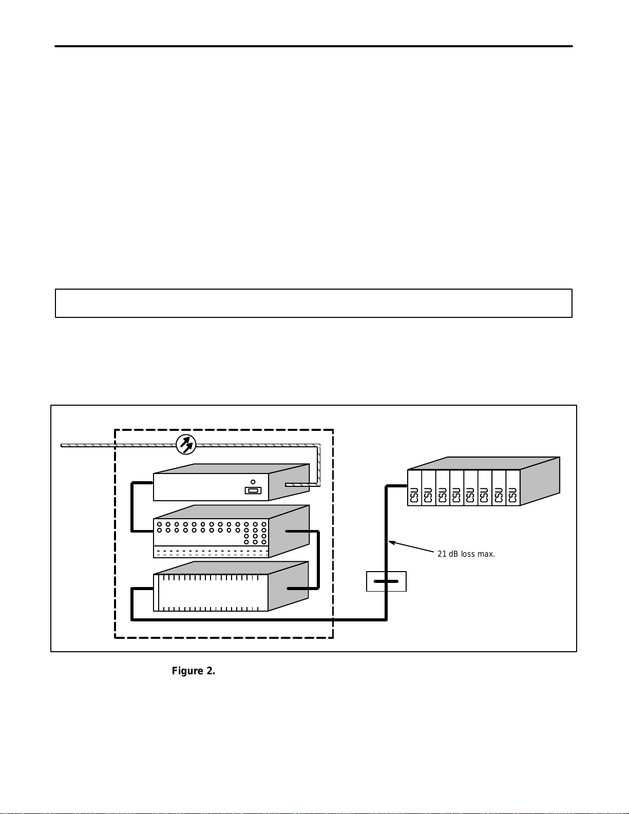
Building Remote Terminal
Fiber
Facility
To LEC
Network
Lightwave
Multiplexer
Customer CPE
DSX-1 Crossconnect
3192–11 STS
Equipment Shelf
e/w 28 ea. 3192–9E
Network
Equipment
21 dB loss max.
Interface
Figure 2. 3192–9E T1 Powering NIU Typical Configuration
2
Section 319-29E-202
2. APPLICATION ENGINEERING
The 3192–9E is ideally suited for use in provisioning T1 High Capacity Digital Service (HCDS) from lightwave-fed
building Remote Terminals located at customer premise locations. See Figure 2 for a typical application. The
3192–9E, used as adjunct equipment to the Lightwave Multiplexer, provides transmission loopback for maintenance activities. In addition, the 3192–9E can be optioned to provide a 60mA constant current power source towards the network interface, which can be used to power the customers’ Channel Service Unit (CSU). This service arrangement is typical in MPOP (Minimum Point Of Presence) applications.
The 3192–9E is intended to be co-located with the lightwave transport equipment and serves to extend the normal DSX range of that equipment. The 3192–9E provides a fixed DSX pre-equalizer for 0 to 110 feet of cable. In
the transmit direction the unit provides variable pads for level coordination toward the CPE. The 3192–9E can
accommodate up to 21dB of cable loss between the customer’s CSU and the 3192–9E.
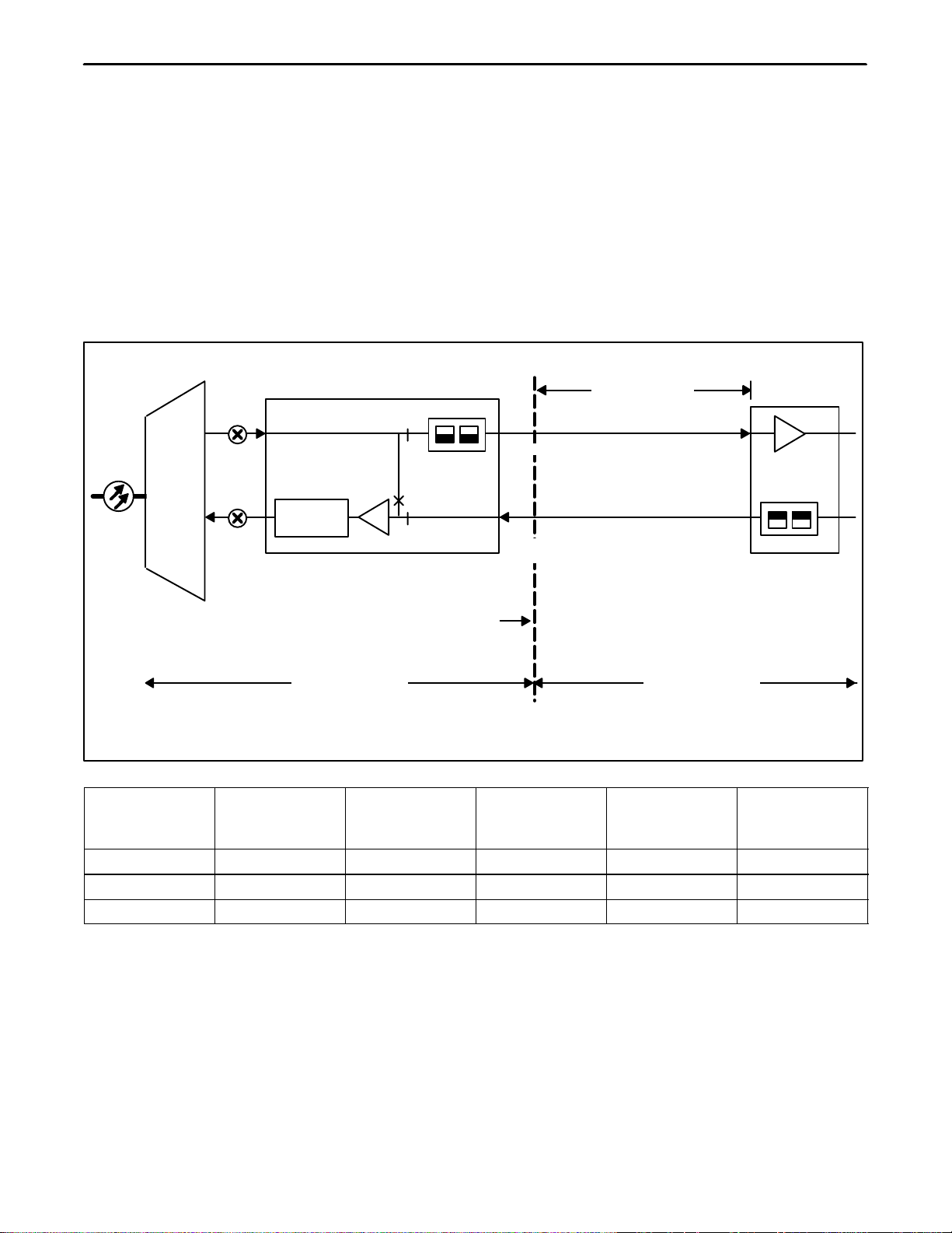
Figure 3 shows a typical 3192–9E application with associated transmission levels.
Customer
Wiring
Maximum
Loss 21.0dB
(See NOTE)
Lightwave
Multiplexer
DSX–1
0.0
Pre
Equalizer
3192–9E Powering T1 NIU
Customer
Network
Interface
LEC Equipment CPE Equipment
–1.5dB
-1.5 To
-22.5dB
Note:
Signal Levels Referenced
To 3V Base-To-Peak
–1.5 To
–22.5dB
LBO
–1.5dB
0.0
T1 CSU
Note: Range is limited to maximum cable loss of 21.0db. See table below for maximum cable length at
various cable gauges.
CABLE @ 130 F
AERIAL - PIC
MAXIMUM
LENGTH -KF
TOTAL DCR
@ MAXIMUM
REFERENCE
LOSS - dB/KF
REFERENCE
LOSS - OHMS/
KF
REFERENCE
MAXIMUM
LOSS
22 GA-CU 4.29 KF 78 OHMS 4.9 dB/KF 18.3 OHMS 21.0dB
24 GA-CU 3.44 KF 100 OHMS 6.1 dB/KF 29.2 OHMS 21.0dB
26 GA-CU 2.56 KF 119 OHMS 8.2 dB/KF 46.7 OHMS 21.0dB
Figure 3. 3192–9E T1 Powering NIU Typical Configuration
2.1 Customer Interface Powering Options
The 3192–9E provides three, switch-selectable, CI (Customer Interface) side power modes: line powering, sealing current, and looped simplex. See Part 6 for more information.
2.2 System Power Engineering
The 3192–9E generates all necessary voltages for its operation from a –48V (nominal) battery input source. The
3192–9E contains an internal high efficiency DC–DC converter to minimize input current, and consequently, maximize battery reserve time in the remote terminal assembly.
3
Section 319–29E–202
Simple
The 3192–9E input current is highly dependent on application. Those applications that require the 3192–9E to
power a customer’s CSU will require a greater input current.
Table 1 shows input current and heat release versus the equivalent series simplex resistance (at 60mA) present
on the CI side of the unit.
Table 1. 3192–9E Power Consumption and Heat Release
Typical Application Option S1
Position
Non-CPE Powering S1 = LP N/A 0.07 2.86 0.06 2.87 0.06 3.00
Sealing Current Only S1 = SC 0 Ohms 0.08 3.35 0.07 3.53 0.07 3.77
S1 = PWR 200 Ohms 0.10 2.91 0.08 3.02 0.07 3.12
S1 = PWR 400 Ohms 0.11 3.04 0.10 3.12 0.08 3.18
Powering Co-located 24V CSU S1 = PWR 600 Ohms 0.13 3.09 0.11 3.12 0.10 3.13
S1 = PWR 800 Ohms 0.14 3.18 0.13 3.13 0.11 3.14
S1 = PWR 1000 Ohms 0.16 3.22 0.14 3.18 0.13 3.15
Powering Co-located 68V CSU S1 = PWR 1200 Ohms 0.18 3.32 0.16 3.22 0.14 3.22
S1 = PWR 1400 Ohms 0.20 3.45 0.18 3.23 0.16 3.28
S1 = PWR 1600 Ohms 0.22 3.55 0.20 3.38 0.18 3.39
Equivalent
External
x
Resistance
–42.5 Volt
Battery
I W I W I W
48.0 Volt Battery
56.0 Volt Battery
Note: W = Heat release in watts
I = Input current in amps
2.3 Maintenance Loopback
The 3192–9E provides a signal path Loopback feature, which can be used to differentiate circuit problems on either side of the network interface.
The 3192–9E will respond to Loopback control codes in either SF or ESF protocols. SF control codes are received as 5 or 6 bit inband repeating patterns, while ESF codes are via 16 bit messages in the ESF framing data
link. The operation of this feature is automatic, that is, when the unit is passing unframed or SF framed traffic it
will recognized the 5 or 6 bit inband SF Loop codes, when the unit is passing ESF traffic it will only recognize the
ESF data link Loopback control codes.
When the 3192–9E is in the maintenance loopback state, it will send an AIS (all ones) signal toward the Customer Interface.
3. CIRCUIT DESCRIPTION
Refer to Figure 4, the 3192–9E Block Diagram, Figure 5, the 3192–9E State Table, and Figure 6, Front Panel
Features and Options Location, when reading the following circuit description.
4

Section 319-29E-202
LIGHTWAVE
MULTIPLEXER
DSX
FA
-BATT
GND
FRA
MEGND
A
1
Network
Side
B
2
10
8
5
J
MON RPT
MON RPT
FA
XMT
RCV
POWER
SUPPLY
NETWORK
SIGNAL
DETECTOR
LOOPBACK
CODE
DETECTOR
CONTROL
LOGIC
LB
MLB
PREEQ
STEADY = LOS
FLASH = AIS
S2
DSX
NET LOS
ESF
LB
LOOPDOWN
CONTROL
SIGNAL
REGEN
LB
AIS
GENERATOR
CI LOS
GENERATOR
LB
BUFFER
AMP
-48V
LB
DISABLE
ENABLE
DISABLE
AIS
FLASH = SENDING AIS
STEADY = CI LOS
AIS
+
ASPR
0-96V
-
7.5 7.5
XMT LBO
S4
S3-2
PWR
LP
4K
100
LB
CUSTOMER
INTERFACE
DETECTOR
SC
SIGNAL
CPE
EQUIPMENT
NETWORK
INTERFACE
SURGE
PROTEC
TION
CSU
F
6
-
XMT
+
S1
+
RCV
-
SURGE
PROTEC
TION
CI
Side
K
9
DISABLE
LOS
S3-1
LOS ALM
H
ALM
RECEIVE
LOOPUP SIGNAL FROM
NETWORK
OR MLB
Figure 4. 3192–9E T1 Powering NIU Block Diagram
IDLE
STATE 1
20 MIN.
TIMEOUT
LOOPBACK
STATE 2
DETECT LOS FROM
CUSTOMER INTERFACE
DETECT SIGNAL PRESENT
CUSTOMER INTERFACE
RECEIVE LOOPUP SIGNAL
RECEIVE
FROM NETWORK
LOOPDOWN
SIGNAL FROM
NETWORK
OR MLB
DETECT SIGNAL PRESENT
CUSTOMER INTERFACE
RECEIVE LOOPUP SIGNAL
FROM NETWORK
Figure 5. 3192–9E Operational State Table
CI LOS
NOTIFICATION
STATE 3
RECEIVE
LOOPDOWN
SIGNAL FROM
NETWORK
CI LOS
CUT-THRU
STATE 4
5
 Loading...